WO2010084570A1 - プロジェクト管理支援装置 - Google Patents
プロジェクト管理支援装置 Download PDFInfo
- Publication number
- WO2010084570A1 WO2010084570A1 PCT/JP2009/050761 JP2009050761W WO2010084570A1 WO 2010084570 A1 WO2010084570 A1 WO 2010084570A1 JP 2009050761 W JP2009050761 W JP 2009050761W WO 2010084570 A1 WO2010084570 A1 WO 2010084570A1
- Authority
- WO
- WIPO (PCT)
- Prior art keywords
- task
- line table
- storage unit
- information storage
- date
- Prior art date
- Legal status (The legal status is an assumption and is not a legal conclusion. Google has not performed a legal analysis and makes no representation as to the accuracy of the status listed.)
- Ceased
Links
Images











Classifications
-
- G—PHYSICS
- G06—COMPUTING OR CALCULATING; COUNTING
- G06Q—INFORMATION AND COMMUNICATION TECHNOLOGY [ICT] SPECIALLY ADAPTED FOR ADMINISTRATIVE, COMMERCIAL, FINANCIAL, MANAGERIAL OR SUPERVISORY PURPOSES; SYSTEMS OR METHODS SPECIALLY ADAPTED FOR ADMINISTRATIVE, COMMERCIAL, FINANCIAL, MANAGERIAL OR SUPERVISORY PURPOSES, NOT OTHERWISE PROVIDED FOR
- G06Q10/00—Administration; Management
- G06Q10/06—Resources, workflows, human or project management; Enterprise or organisation planning; Enterprise or organisation modelling
Definitions
- the present invention relates to a project management support apparatus that manages each task as a WBS (Work Breakdown Structure) and displays a line table indicating the progress of each task.
- WBS Work Breakdown Structure
- Non-Patent Document 1 discloses a system that subdivides a project into a plurality of tasks, manages them as a WBS, and displays the progress of each task.
- the present invention has been made in view of the above circumstances, and an object of the present invention is to allow a project manager to easily distinguish and recognize a business having a high delay risk and a business having a low delay risk.
- the present invention displays a task line table having a high delay risk in a color, a hatching pattern, or a combination thereof different from that of a task table having a low delay risk.
- the present invention is a project management support apparatus that manages each task included in a project as WBS (Work Breakdown Structure) and displays a line chart indicating the progress of each task, and includes a task ID for identifying each task.
- WBS Work Breakdown Structure
- the task information storage unit that stores a summary flag that indicates whether the task has a lower-level task and a summary flag that indicates that there is no lower-level task by referring to the task information storage unit
- the task ID of the end task that is the attached task is extracted, and each task corresponding to the extracted task ID is extracted.
- a line table indicating the implementation period and the progress rate is created using the scheduled start date, the scheduled completion date, and the progress rate associated with the task ID to indicate that the task has a high delay risk.
- the color, hatching pattern, or a combination of these is different from the line table of the end task associated with the mode indicating that the task indicating that the delay risk is not high in the line table of the end task associated with the mode indicated.
- a project management support apparatus comprising: a line table creation unit for setting.
- the project management support apparatus of the present invention it is possible for the project manager to easily distinguish and recognize a business with a high delay risk and a business with a low delay risk.
- FIG. 1 is a system configuration diagram illustrating an example of a project management support system 10 according to an embodiment of the present invention.
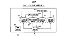
- 3 is a block diagram illustrating an example of a functional configuration of a project management support apparatus 20.
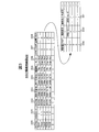
- FIG. 6 is a diagram illustrating an example of a structure of data stored in a mode setting unit 23.
- FIG. 4 is a diagram illustrating an example of a structure of data stored in a data management unit 25.
- FIG. 4 is a diagram illustrating an example of a structure of data stored in a study period storage unit 28.
- FIG. It is a conceptual diagram which shows an example of a data management screen 30 screen structure. It is a conceptual diagram which shows an example of a structure of the data management screen 30 at the time of registering data.
- FIG. 1 is a system configuration diagram showing an example of a project management support system 10 according to an embodiment of the present invention.
- the project management support system 10 includes an administrator terminal 12, an experimental device 13, and a project management support device 20.
- the administrator terminal 12, the experimental apparatus 13, and the project management support apparatus 20 are connected to the communication line 11 and communicate with each other via the communication line 11.
- the administrator terminal 12 is operated by, for example, a project manager, and in response to the operation of the manager, for each of a plurality of tasks (businesses) to be executed in the project, information on the task is transmitted to the communication line 11.
- a plurality of tasks included in a project are managed as WBS (Work Breakdown Structure).
- the manager terminal 12 acquires a line table indicating the implementation period and progress rate of each task included in the project from the project management support apparatus 20 and displays it in accordance with the operation of the project manager or the like.
- the administrator terminal 12 is a general-purpose computer, for example.
- the experiment device 13 is operated by the person in charge of each task, performs an experiment on the deliverable output by executing the task, and supports the project management along with the task ID of the task via the communication line 11. Transmit to device 20.
- the project management support device 20 creates a line table indicating the execution period and progress rate of each task based on the information regarding the task received from the administrator terminal 12 via the communication line 11. In response to the request, the created line table is provided to the administrator terminal 12 via the communication line 11.
- FIG. 2 is a block diagram illustrating an example of a functional configuration of the project management support apparatus 20.
- the project management support apparatus 20 includes a line table creation unit 21, a task information storage unit 22, a mode setting unit 23, a detailed plan information storage unit 24, a data management unit 25, a replan setting unit 26, an experiment information storage unit 27, and a study.
- a period storage unit 28 is included.
- the task information storage unit 22 is associated with a task ID 220 for identifying each of a plurality of tasks included in the project, and includes a WBS code 221 indicating the position of the task in the project, Task name 222, scheduled start date 223 of the task, scheduled completion date 224 of the task, progress rate 225 of the task, mode 226 indicating whether or not the task has a high delay risk, and tasks exist below the task
- a summary flag 227 indicating whether or not to perform
- a folding flag 228 indicating whether or not to display a lower-level task line table when displaying the task line table, and whether or not it is necessary to re-plan the task
- a re-planning flag 229 indicating a re-planning date 230 indicating a date when it is determined that it is necessary to re-plan the task.
- Study completion date 231, etc. are expected date completed realigning plan of the task are stored and.
- “High ⁇ ⁇ ⁇ Risk” is set in the mode 226 of the task with a high delay risk
- “Low Risk” is set in the mode 226 of the task with a low delay risk.
- the initial value of the mode is “High Risk”.
- “1” is set in the summary flag 227 of a task having a task at a lower level
- “0” is set in the summary flag 227 of a task at a lower level, that is, no task at a lower level.
- the task folding flag 228 is set to “1” for displaying the line table of the invoking task and not displaying the line table of the inferior task, and displays the line table of the inferior task together with the line table of the invoking task.
- “0” is set.
- “1” is set in the re-planning flag 229 of the task that needs to be re-planned
- “0” is set in the re-planning flag 229 of the task that does not need to be re-planned.
- the initial value of the re-planning flag is “0”.
- a plurality of documents indicating detailed plan information may be created for one task.
- a plurality of document names and approval dates are associated with the same task ID. .
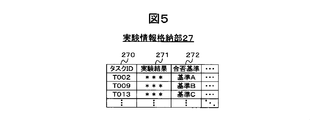
- the experiment result 271 of the deliverable output in the task and the pass / fail of the experiment result 271 are associated with the task ID 270 for identifying each task.
- the reference 272 and the like are stored.
- the examination period storage unit 28 stores the number of days (for example, seven days) that is the initial value of the examination period.
- the data management unit 25 creates, for example, a data management screen 30 as shown in FIG. 6 when requested by the administrator terminal 12 via the communication line 11 for a data management screen for inputting information relating to a task. And provided to the administrator terminal 12. In an area 31 on the left side of the data management screen 30, a menu 32 indicating items such as the type of information to be registered and display of a line table, and an end button 33 are displayed.
- the administrator terminal 12 receives the data management screen 30 from the project management support apparatus 20 via the communication line 11 and displays it.
- a project manager or the like operates the administrator terminal 12 and selects any item indicating the type of information to be registered in the menu 32, the administrator terminal 12 displays a screen corresponding to the selected item as data. The information is displayed in the area 34 on the right side of the management screen 30.
- FIG. 7 illustrates a data management screen 30 when a task information item is selected in the menu 32.
- an input box 35 for inputting information corresponding to the item and a registration button 36 are displayed.
- the administrator terminal 12 transmits the information input in the input box 35 to the project management support apparatus 20 via the communication line 11 for each item.
- the data management unit 25 of the project management support apparatus 20 registers the task information for each item received from the administrator terminal 12 in the task information storage unit 22.
- the administrator terminal 12 When information is input to the input box 35 corresponding to the task ID, the administrator terminal 12 transmits the information as a task ID to the project management support apparatus 20, and the data management unit 25 includes a task information storage unit. Referring to FIG. 22, information associated with the task ID received from the administrator terminal 12 is extracted for each item and returned to the administrator terminal 12. Then, the administrator terminal 12 displays the received information on the input box 35 for each item. Thereby, the manager of the project who operates the administrator terminal 12 can not only newly register the task information but also correct a part of the already registered task information.
- FIG. 8 illustrates the data management screen 30 when the item of detailed plan information is selected in the menu 32.
- an input box 35 for inputting information corresponding to the item for each item included in the detailed plan information and a registration button 36 are displayed.
- the administrator terminal 12 transmits the information input in the input box 35 to the project management support apparatus 20 via the communication line 11 for each item.
- the data management unit 25 of the project management support apparatus 20 registers the detailed plan information for each item received from the administrator terminal 12 in the detailed plan information storage unit 24.
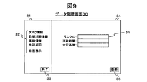
- FIG. 9 illustrates a data management screen 30 when the item of experiment information is selected in the menu 32.
- an input box 35 for inputting information corresponding to the item for each item included in the experiment information, and a registration button 36 are displayed.
- the administrator terminal 12 transmits the information input in the input box 35 to the project management support apparatus 20 via the communication line 11 for each item.
- the data management unit 25 of the project management support apparatus 20 registers the experiment information for each item received from the administrator terminal 12 in the experiment information storage unit 27.
- FIG. 10 illustrates the data management screen 30 when the item for the examination period is selected in the menu 32.
- an input box 35 for inputting the examination period and a registration button 36 are displayed.
- the manager terminal 12 transmits the examination period input in the input box 35 to the project management support apparatus 20 via the communication line 11.
- the data management unit 25 of the project management support apparatus 20 registers the examination period received from the administrator terminal 12 in the examination period storage unit 28.
- the manager terminal 12 requests the line table from the project management support apparatus 20 via the communication line 11.
- the line table creation unit 21 displays the line table of the highest-level task created in advance via the communication line 11 together with the task ID of the task. 12 to send. A method for creating the line table will be described later.
- the administrator terminal 12 displays the line table received from the project management support apparatus 20 in the area 34 on the right side of the data management screen 30 as shown in FIG.
- a task line table 39 corresponding to the task name 37 and a fold for controlling the folding display of the line table 39 are displayed.
- Button 38 is displayed.
- the line table 39 displays a line 390 indicating the current time.
- the line tables of all the lower tasks are superimposed and displayed.
- the administrator terminal 12 manages the task ID of the task corresponding to the task name 37 in association with the task name 37.
- the task folding button 38 displays “+” indicating that the task is folded.
- the lower task line table 39 is displayed in addition to the upper task line table 39, that is, when the lower task line table is expanded and displayed, for example, as shown in FIG. “ ⁇ ” Indicating that the upper task is not folded is displayed on the folding button 38 of the upper task, and below the upper task line table 39, the lower task line table 39 includes the task name 37 and the task name 37, respectively. Displayed with the fold button 38.
- the display is changed to “ ⁇ ” if “+” and “+” if “ ⁇ ”.
- the administrator terminal 12 displays the display of the fold button 38 as “ ⁇ ”.
- the folding information indicating that the line table has been expanded in association with the task ID associated with the task name 37 is transmitted to the project management support apparatus 20 via the communication line 11.
- the data management unit 25 refers to the task information storage unit 22 based on the task ID received from the administrator terminal 12 and the folding information indicating that the line table has been expanded, and the folding associated with the task ID. Set the tatami flag to “0”. Then, the line table creation unit 21 creates a task line table according to the folding flag, and transmits the created line table to the administrator terminal 12. Then, for example, as shown in FIG. 12, the manager terminal 12 displays the line table 39 of the highest-level task A received from the project management support apparatus 20, and below the line table 39 of the task A, The line table 39 from the lower task B to the task F immediately below the task A is displayed together with the task name 37 and the folding button 38.
- the data management unit 25 receives the experimental result together with the task ID from the experimental device 13 via the communication line 11, the received data is registered in the experimental information storage unit 27 in association with the received task ID. To do.
- the line table creation unit 21 refers to the task information storage unit 22 and sets the task ID of the end task that is a task for which “0” is set in the summary flag. For each terminal task that is extracted and corresponds to the extracted task ID, the period from the planned start date to the planned completion date using the planned start date, scheduled completion date, and progress rate associated with the task ID A line table showing the implementation period and the progress rate is created.
- the line table creation unit 21 extracts the task ID of the end task for which “1” is set in the re-planning flag, and associates each end task corresponding to the extracted task ID with the task ID.
- a line table showing the re-planning period from the re-planning date to the planned completion date is further created.
- the line table creation unit 21 refers to the mode setting unit 23, and the line table of the end task whose mode is set to “Low Risk” and the line table of the end task whose mode is set to “Low Risk”. Hatch different from that.
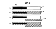
- the line table creation unit 21 applies a plain hatching (or no hatching) as shown in FIG. 13A to the line table of the end task whose mode is set to “Low Risk”, for example.
- hatching as shown in FIG. 13B is applied to the line table of the end task whose mode is set to “High Risk”.
- the line table creation unit 21 applies hatching different from any line table indicating the implementation period and the progress rate to the created line table of the examination period, for example, as illustrated in FIG. It is placed directly under the line table showing the implementation period and progress rate.
- reference numeral 40 denotes a progress rate line table
- reference numeral 41 denotes a line table of the execution period of the end task in which “Low ⁇ Risk ”is set in the mode
- reference numeral 42 denotes the mode.
- a line table of the execution period of the end task for which “High Risk” is set is shown
- reference numeral 43 shows a line table of a re-planning period which is a period for re-planning the plan.
- the line table creation unit 21 creates a line table for the upper task by superimposing the line tables of the lower tasks for each upper task whose summary flag is set to “1”.
- “High Risk” is set in the mode
- “1” is set in the re-planning flag
- “Low Risk” is set in the mode. ”Is set
- task C is set to“ 0 ”in the re-planning flag
- “ High ⁇ Risk” is set in the mode
- task D is set to “0” in the re-planning flag.
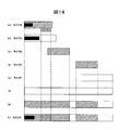
- the line table creation unit 21 sets the scheduled start date of the task with the earliest scheduled start date as the start date, and the scheduled completion date of the task with the latest scheduled completion date as the end date. . Then, for example, as shown in FIG. 14 (f), the line table creation unit 21 creates a line table indicating the implementation period from the start date to the end date. The same hatching as the line table of the set task execution period (solid hatching in this embodiment) is applied.
- the line table creation unit 21 sets the mode to “High” in the execution period portion of the task for which “High Risk” is set.
- the same hatching as the line table of the execution period of the task for which “Risk” is set is applied.
- the line table creating unit 21 re-executes the re-planning part in the execution period portion of the task for which “1” is set.
- the same hatching as the line table of the re-planning period of the task for which “1” is set in the plan flag is applied.
- the line table creation unit 21 extracts the progress rate of task A from the task information storage unit 22, and the length of the task A implementation period (FIG. 14 (f)) is 100%.
- the length of the progress rate line table a line table having a length corresponding to the extracted progress rate is arranged on the line table of the task A implementation period.
- the mode setting unit 23 specifies a task ID associated with the registered approval date.
- the mode setting unit 23 refers to the task information storage unit 22 when the approval date is associated with all document names associated with the specified task ID in the detailed plan information storage unit 24. Then, “Low Risk” is set in the mode associated with the task ID.
- “High Risk” is set as an initial value in the mode in the task information storage unit 22, and the mode setting unit 23 sets a task ID that is not associated with an approval date in the detailed plan information storage unit 24.
- the mode associated with the task ID remains “High Risk”.
- the reschedule setting unit 26 When the experiment result is registered in the experiment information storage unit 27 with reference to the experiment information storage unit 27, the reschedule setting unit 26 satisfies the acceptance criteria associated with the experiment result. It is determined whether or not.
- the re-plan setting unit 26 extracts the task ID associated with the experiment result from the experiment information storage unit 27, for example, the date when the experiment result is registered is the re-plan date, A date obtained by adding the examination period stored in the examination period storage unit 28 to the re-planning date is registered in the task information storage unit 22 in association with the extracted task ID as the examination completion scheduled date. Then, the replan setting unit 26 refers to the task information storage unit 22 and sets “1” to the replan flag corresponding to the extracted task ID.
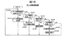
- FIG. 15 is a flowchart illustrating an example of the data management process. For example, at a predetermined timing such as when the power is turned on, the project management support apparatus 20 starts the data management process shown in this flowchart.
- the data management unit 25 determines whether a data management screen is requested from the administrator terminal 12 (S100). When the data management screen is requested (S100: Yes), the data management unit 25 creates, for example, the data management screen described with reference to FIG. 6 and transmits it to the administrator terminal 12 (S101), again shown in step S100. Execute the process.
- the data management unit 25 determines whether task information, document information, experiment results, or task information that is a study period has been received (S102). When the task information is received (S102: Yes), the data management unit 25 stores the received task information in the task information storage unit 22, the detailed plan information storage unit 24, the experiment information storage unit 27, or the examination period storage unit 28. Register (S103) and execute the process shown in step S100 again.
- the line table creation unit 21 determines whether a line table is requested from the administrator terminal 12 (S104). When the line table is requested (S104: Yes), the line table creation unit 21 transmits the line table of the highest task created in advance to the administrator terminal 12 (S105), and the data management unit 25 The process shown in step S100 is executed again. If “0” is set in the folding flag of the highest task in step S105, the line table creation unit 21 not only displays the line table of the highest task but also the line table of the lower task. It transmits to the administrator terminal 12.
- the data management unit 25 determines whether or not the fold information indicating whether or not the line table is expanded is received together with the task ID (S106). When the folding information is not received (S106: No), the data management unit 25 executes the process shown in step S100 again.
- the data management unit 25 associates the task information with the task ID received together with the folding information if the folding information indicates that the line table is expanded. If the folding flag registered in the storage unit 22 is rewritten to “0” and the folding information indicates that the line table is folded, task information is stored in association with the task ID received together with the folding information. The folding flag registered in the unit 22 is rewritten to “1” (S107). Then, the line table creation unit 21 creates a line table based on the updated information in the task information storage unit 22, transmits the created line table to the administrator terminal 12 (S108), and the data management unit 25 The process shown in step S100 is executed again.
- FIG. 16 is a flowchart showing an example of a line table creation process.
- the line table creation unit 21 starts the operation shown in this flowchart when the information in the task information storage unit 22 is updated.
- the line table creation unit 21 refers to the WBS code in the task information storage unit 22 and identifies the task ID of the highest task (S110). Then, the line table creation unit 21 executes a line table creation detail process (S200), and ends the line table creation process shown in this flowchart.
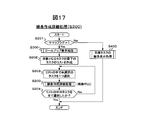
- FIG. 17 is a flowchart showing an example of a line table creation detail process (S200).
- the line table creation unit 21 sets the mode setting unit 23 based on the task ID specified in step S110 (or the task ID selected in step S203 of the previous step S200 when the current step S200 is a recursive call). It is determined whether or not “1” is set in the summary flag associated with the task ID (S201). When “0” is set in the summary flag (S201: No), the line table creation unit 21 executes a line table display process of the end task described later (S400), and performs the line table creation detailed process shown in this flowchart. finish.
- step S300 the line table creation unit 21 executes a roll-up process to be described later (S300).
- step S300 the task line corresponding to the task ID specified in step S110 (or the task ID selected in step S203 of the previous step S200 if the current step S200 is a recursive call).
- a table is created.
- the line table creation unit 21 refers to the WBS code in the mode setting unit 23 and identifies the task ID specified in step S110 (if the current step S200 is a recursive call, step S203 of the previous step S200).
- a list of tasks located one hierarchy lower than the task corresponding to the task ID selected in (1) is created (S202).
- the line table creation unit 21 selects one task ID of an unselected task in the created list (S203), and executes line table creation detailed processing by recursive call (S200). Then, the line table creation unit 21 determines whether all the tasks in the list created in step S202 have been selected (S204). If there is an unselected task in the list (S204: No), the line table creation unit 21 executes the process shown in step S203 again. When all the tasks in the list are selected (S204: Yes), the line table creation unit 21 ends the line table creation detailed process shown in this flowchart path.
- FIG. 18 is a flowchart showing an example of the roll-up display process (S300).
- the line table creation unit 21 creates a list of end tasks that are selected in step S110 of FIG. 16 or step S203 of FIG. Create (S301). For example, as illustrated in FIG. 14, when the end task corresponding to task A is from task B to task F, the line table creation unit 21 creates a list indicating task F from task B.
- the line table creation unit 21 holds the scheduled start date of the task with the earliest scheduled start date in the list as a start date (S302), and the scheduled completion date of the task with the latest scheduled completion date in the list. Is held as the end date (S303). Then, the line table creation unit 21 creates a line table indicating the implementation period from the start date to the end date as shown in FIG. 14F, for example (S304). The same hatching (solid hatching in this embodiment) as the line table of the execution period of the task for which “Low Risk” is set is applied (S305).
- the line table creation unit 21 refers to the task information storage unit 22 and extracts the task ID of the task whose mode is set to “High Risk” from the list created in step S301 (S306). ). Then, the line table creation unit 21 executes an overwrite list creation process for a task whose mode is set to “HighkRisk” (S500). When step S500 is executed, an overwrite list, which is a list of a plurality of periods, is created for a task whose mode is set to “HighkRisk”.
- the line table creation unit 21 switches to the mode during each period included in the overwrite list created in step S500 in the line table created in step S305.
- the same hatching as the line table of the execution period of the task for which “High Risk” is set is applied (S307).
- the line table creation unit 21 refers to the task information storage unit 22 and extracts the task ID of the task for which “1” is set in the re-planning flag from the list created in step S301 ( S308).
- the line table creation unit 21 then executes an overwrite list creation process for a task for which “1” is set in the re-planning flag (S600).
- an overwrite list which is a list of a plurality of periods, is created for a task for which “1” is set in the re-planning flag.
- the line table creation unit 21 re-plans each period included in the overwrite list created in step S600 in the line table created in step S307.
- the same hatching as the line table of the review period of the task for which “1” is set in the flag is applied (S307).
- the line table creation unit 21 extracts the task progress rate corresponding to the task ID selected in step S110 of FIG. 16 or step S203 of FIG. 17 from the task information storage unit 22, and the line corresponding to the extracted progress rate.
- the table is arranged so as to overlap the line table created in step S307 (S310), and the line table creation unit 21 ends the roll-up display process shown in this flowchart.
- FIG. 19 is a flowchart showing an example of an overwrite list creation process (S500) for a task for which “High Risk” is set as the mode.
- S500 overwrite list creation process
- the line table creation unit 21 refers to the task information storage unit 22 and selects one task ID associated with the earliest scheduled start date from the task IDs extracted in step S306 in FIG. (S501). Then, the line table creation unit 21 sets the scheduled start date and the scheduled completion date associated with the selected task ID as the scheduled launch date and the scheduled completion date for the first period (S502).
- the line table creation unit 21 sets 1 to the variable n (S503), and determines whether or not an unselected task ID exists among the task IDs extracted in step S306 in FIG. 18 ( S504).
- the line table creation unit 21 creates an overwrite list including each of the first to n-th periods as a list (S511), and the line table creation unit 21 Then, the overwrite list creation process shown in this flowchart is terminated.
- the line table creation unit 21 selects one task ID associated with the earliest scheduled start date from among the unselected task IDs ( S505). Then, the line table creation unit 21 refers to the task information storage unit 22 and determines whether or not the scheduled start date associated with the selected task ID is after the scheduled completion date of the nth period. (S506).
- the line table creation unit 21 refers to the task information storage unit 22 Whether or not the scheduled completion date associated with the task ID selected in step S505 is later than the scheduled completion date of the nth period is determined (S507).
- the line table creation unit 21 performs the process shown in step S504 again. Execute.
- step S507 When the scheduled completion date associated with the selected task ID is later than the scheduled completion date of the nth period (S507: Yes), the line table creation unit 21 corresponds to the task ID selected in step S505. The attached scheduled completion date is set to the scheduled completion date of the nth period (S508), and the process shown in step S504 is executed again.
- the line table creation unit 21 When the scheduled start date associated with the selected task ID is later than the scheduled completion date of the nth period (S506: Yes), the line table creation unit 21 increases the variable n by 1 (S509). . Then, the line table creation unit 21 sets the scheduled start date and the scheduled completion date associated with the task ID selected in step S505 to the scheduled start date and scheduled completion date of the nth period (S510). The process shown in step S504 is executed again.
- FIG. 20 is a flowchart showing an example of the overwrite list creation process (S600) for a task for which “1” is set in the re-planning flag.
- the line table creation unit 21 refers to the task information storage unit 22 and selects one task ID associated with the earliest replan date from the task IDs extracted in step S308 in FIG. (S601). Then, the line table creation unit 21 sets the replan date and the estimated completion date associated with the selected task ID as the replan date and the estimated completion date for the first period (S602).
- the line table creation unit 21 sets 1 to the variable n (S603), and determines whether or not an unselected task ID exists among the task IDs extracted in step S308 of FIG. S604).
- the line table creation unit 21 creates an overwrite list including each of the first to n-th periods as a list (S611), and the line table creation unit 21 Then, the overwrite list creation process shown in this flowchart is terminated.
- the line table creation unit 21 selects one task ID associated with the earliest replan date among the unselected task IDs ( S605). Then, the line table creation unit 21 refers to the task information storage unit 22 and determines whether or not the re-planning date associated with the selected task ID is later than the scheduled completion date for the nth period. (S606).
- the line table creation unit 21 refers to the task information storage unit 22 Then, it is determined whether or not the planned study completion date associated with the task ID selected in step S605 is later than the planned study completion date in the nth period (S607).
- the scheduled study completion date associated with the selected task ID is the same date as or before the scheduled study completion date in the nth period (S607: No)
- the line table creation unit 21 again shows in step S604. Execute the process.
- step S607 When the scheduled study completion date associated with the selected task ID is later than the scheduled study completion date of the nth period (S607: Yes), the line table creation unit 21 selects the task ID selected in step S605. Is set to the scheduled completion date of the nth period (S608), and the process shown in step S604 is executed again.
- the line table creation unit 21 increases the variable n by 1 (S609). ). Then, the line table creation unit 21 sets the replan date and the scheduled study completion date associated with the task ID selected in step S605 to the replan date and the scheduled study completion date for the nth period (S610). ) The process shown in step S604 is executed again.
- FIG. 21 is a flowchart showing an example of the end task line table display process (S400).
- the line table creation unit 21 refers to the task information storage unit 22 based on the task ID selected in step S203 in FIG. 17, and starts the scheduled start date, scheduled completion date, and progress associated with the task ID. Using the rate, a line table indicating the execution period and progress rate of the task corresponding to the task ID is created (S401).
- the line table creation unit 21 refers to the task information storage unit 22 and determines whether or not “HighisRisk” is set in the mode associated with the task ID of the task that created the line table in step S401. Is determined (S402). When “Low Risk” is set in the mode (S402: No), the line table creation unit 21 indicates “Low Risk” in the line table created in step S401, for example, as shown in FIG. Hatching (in this embodiment, plain hatching) is applied (S403). On the other hand, when “High Risk” is set in the mode (S402: Yes), the line table creation unit 21 adds “High Risk” to the line table created in step S401 as shown in FIG. 13B, for example. (S404).
- the line table creation unit 21 refers to the task information storage unit 22 and is “1” set in the replan flag associated with the task ID of the task for which the line table was created in step S401? It is determined whether or not (S405). When “0” is set in the re-planning flag (S405: No), the line table creation unit 21 ends the line table display process shown in this flowchart.
- the line table creation unit 21 When “1” is set in the re-planning flag (S405: Yes), the line table creation unit 21 directly below the line table created in step S401, for example, as shown in FIG. 13 (c) or (d). Then, a line table indicating the re-planning period from the re-planning date to the scheduled completion date for examination is created (S406). Then, the line table creation unit 21 hatches the created line table indicating the re-planning period (S407), and ends the line table display process shown in this flowchart.
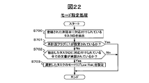
- FIG. 22 is a flowchart illustrating an example of the mode setting process.
- the mode setting unit 23 starts the mode setting process shown in this flowchart.
- the mode setting unit 23 refers to the detailed plan information storage unit 24 and extracts the task ID associated with the newly registered approval date (S700). Then, the mode setting unit 23 refers to the task information storage unit 22 based on the extracted task ID, and determines whether or not “1” is set in the re-planning flag associated with the task ID ( S701). When “1” is set in the re-planning flag (S701: Yes), the mode setting unit 23 ends the mode setting process shown in this flowchart.
- the mode setting unit 23 refers to the detailed plan information storage unit 24 based on the task ID extracted in step S700, and associates it with the task ID. It is determined whether or not an approval date is associated with all the document names (S702). When the approval date is not associated with any document name associated with the task ID extracted in step S700 (S702: No), the mode setting unit 23 ends the mode setting process shown in this flowchart. .
- the mode setting unit 23 displays the information indicating “Low Risk” in association with the task ID extracted in step S700 as the detailed plan information.
- the mode is set in the storage section 24 (S704), and the mode setting process shown in this flowchart is terminated.
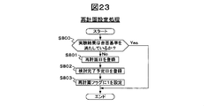
- FIG. 23 is a flowchart illustrating an example of the reschedule setting process.
- the re-plan setting unit 26 refers to the experiment information storage unit 27, and the experiment result newly registered in the experiment information storage unit 27 is registered in the experiment information storage unit 27 in association with the experiment result. It is determined whether or not a pass / fail criterion is satisfied (S800). When the experiment result newly registered in the experiment information storage unit 27 satisfies the corresponding pass / fail criterion (S800: Yes), the re-plan setting unit 26 ends the re-plan setting process shown in this flowchart.
- the replan setting unit 26 associates the experiment result with the experiment result and stores it in the experiment information storage unit 27.
- the stored task ID is extracted.
- the replan setting unit 26 registers, for example, the date when the experiment result is registered in the experiment information storage unit 27 in association with the extracted task ID in the replan date column in the task information storage unit 22. (S801).
- the replan setting unit 26 extracts the review period from the review period storage unit 28, and adds the extracted review period to the replan date registered in step S801, and the task extracted in step S801. In association with the ID, it is registered in the column for the scheduled date of completion of study in the task information storage unit 22 (S802). Then, the replan setting unit 26 sets “1” in the review flag column in the task information storage unit 22 in association with the task ID extracted in step S801 (S803). Then, the re-planning setting process shown in this flowchart is terminated.
- FIG. 24 is a hardware configuration diagram illustrating an example of a hardware configuration of the computer 50 that realizes the functions of the project management support apparatus 20.
- the computer 50 includes a CPU (Central Processing Unit) 51, a RAM (Random Access Memory) 52, a ROM (Read Only Memory) 53, a HDD (Hard Disk Drive) 54, a communication interface (I / F) 55, an input / output interface (I). / F) 56 and media interface (I / F) 57.
- a CPU Central Processing Unit
- RAM Random Access Memory
- ROM Read Only Memory
- HDD Hard Disk Drive
- the CPU 51 operates based on a program stored in the ROM 53 or the HDD 54 and controls each part.
- the ROM 53 stores a boot program executed by the CPU 51 when the computer 50 is started up, a program depending on the hardware of the computer 50, and the like.
- the HDD 54 stores a program executed by the CPU 51, data used in the program, and the like.
- the communication interface 55 receives data from other devices via the communication line 11 and sends the data to the CPU 51, and transmits data generated by the CPU 51 to other devices via the communication line 11.
- the CPU 51 controls an output device such as a display and a printer and an input device such as a keyboard and a mouse via the input / output interface 56.
- the CPU 51 acquires data from the input device via the input / output interface 56. Further, the CPU 51 outputs the generated data to the output device via the input / output interface 56.
- the media interface 57 reads a program or data stored in the recording medium 58 and provides it to the CPU 51 via the RAM 52.
- the CPU 51 loads the program from the recording medium 58 onto the RAM 52 via the media interface 57 and executes the loaded program.
- the recording medium 58 is, for example, an optical recording medium such as DVD (Digital Versatile Disk) or PD (Phase change rewriteable Disk), a magneto-optical recording medium such as MO (Magneto-Optical Disk), a tape medium, a magnetic recording medium, or a semiconductor memory. Etc.
- the CPU 51 of the computer 50 executes a program loaded on the RAM 52 to thereby execute a line table creation unit 21, a task information storage unit 22, a mode setting unit 23, a detailed plan information storage unit 24, a data management unit 25, a re-planning
- the functions of the setting unit 26, the experiment information storage unit 27, and the examination period storage unit 28 are realized.
- the HDD 54 stores data in the task information storage unit 22, the detailed plan information storage unit 24, the experiment information storage unit 27, and the examination period storage unit 28.
- the CPU 51 of the computer 50 reads these programs from the recording medium 58 and executes them, but as another example, the CPU 51 may acquire these programs from other devices via a communication medium.
- the communication medium refers to the communication line 11 or a digital signal or carrier wave that propagates through the communication line 11.
- the project management support system 10 of the present embodiment it is possible for the project manager to easily distinguish and recognize a business having a high delay risk and a business having a low delay risk. This allows project managers to focus on planning and implementing measures for tasks with a high risk of delay, increasing the probability that the project will complete as planned.
- the project management support apparatus 20 includes the task information storage unit 22, the detailed plan information storage unit 24, the experiment information storage unit 27, and the examination period storage unit 28.
- the present invention is not limited to this. I can't.
- these databases are provided in another database server connected to the communication line 11, and the project management support apparatus 20 communicates with the other database server, thereby corresponding to the above-described embodiment.
- the project management support apparatus 20 may be configured to realize the function.
- the line chart of the task in which the mode is set to “Low Risk” is plain hatched, but as another form, “Low Risk” is set in the mode.
- the non-solid hatching which is different from both the task line table in which “High Risk” is set in the mode and the line table indicating the re-planning period, may be applied to the task line table.
- the line chart of the task in which “Low Risk” is set in the mode the line chart of the task in which “High Risk” is set in the mode, and the line table indicating the re-planning period are differently hatched, but as another form, these line tables may be painted with different colors. Further, these three types of line charts may be displayed in a distinguishable form by a combination of color and hatching.
- the mode setting unit 23 executes the mode setting process shown in FIG. 22 every time data is registered in the approval date column in the detailed plan information storage unit 24.
- the mode setting unit 23 A setting process may be executed.
- the replan setting unit 26 executes the replan setting process shown in FIG. 23 each time data is registered in the experiment result column in the experiment information storage unit 27.
- the re-plan setting unit 26 has a predetermined timing, such as once a day, for a task whose data has been registered in the experiment result column in the experiment information storage unit 27 after the previous re-plan setting process.
- the re-plan setting process may be executed.
- the project management support apparatus 20 includes an acquisition function for acquiring the content of an e-mail describing an intermediate report of a task transmitted from the terminal of each person in charge to the administrator terminal 12, and A second re-planning setting function for setting a re-planning flag, a re-planning date, and a planned completion date for the task corresponding to the content based on the content of the e-mail acquired by the acquiring function; Also good.
- the format of the intermediate report transmitted from the terminal of each person in charge to the manager terminal 12 is determined in advance, and the second replan setting function requires replanning at a predetermined position of the intermediate report.
- the task information storage unit 22 is referred to based on the task ID described in the predetermined position of the intermediate report, the re-plan flag is associated with the task ID, Set replan date and review completion period.
- the project management support apparatus 20 can quickly re-execute a task based on an event that requires re-planning that is recognized by the person in charge, even before the work product is created and the experiment of the product is completed.
- a planning period can be set.
Landscapes
- Engineering & Computer Science (AREA)
- Business, Economics & Management (AREA)
- Human Resources & Organizations (AREA)
- Strategic Management (AREA)
- Economics (AREA)
- Entrepreneurship & Innovation (AREA)
- Educational Administration (AREA)
- Game Theory and Decision Science (AREA)
- Development Economics (AREA)
- Marketing (AREA)
- Operations Research (AREA)
- Quality & Reliability (AREA)
- Tourism & Hospitality (AREA)
- Physics & Mathematics (AREA)
- General Business, Economics & Management (AREA)
- General Physics & Mathematics (AREA)
- Theoretical Computer Science (AREA)
- Management, Administration, Business Operations System, And Electronic Commerce (AREA)
Abstract
プロジェクトの管理者に、遅延リスクの高いタスクと遅延リスクの低いタスクとを容易に区別して認識させることができるプロジェクト管理支援装置20を提供する。 本発明のプロジェクト管理支援装置20は、計画が練り直しとなったタスクにおける再計画期間の線表と、遅延リスクの高いタスクの線表と、遅延リスクの低いタスクの線表とを、異なる色、ハッチングパターン、またはそれらの組み合わせで区別して表示する。
Description
本発明は、各タスクをWBS(Work Breakdown Structure)として管理し、各タスクの進捗を示す線表を表示するプロジェクト管理支援装置に関する。
例えば下記の非特許文献1には、プロジェクトを複数の業務に細分化してWBSとして管理し、それぞれの業務の進捗を表示するシステムが開示されている。
内舘町子著、「ひと目でわかるMicrosoft Office Project 2007」、日経BPソフトプレス、2007年3月
プロジェクトの管理においては、実際に遅延が発生する前に、遅延の発生リスクのある業務について対策を講じ、プロジェクト全体が当初の計画から遅延しないように各業務を管理する必要がある。上記した非特許文献1では、計画から遅延している業務を稲妻線等で明示するが、遅延が発生する前の業務については、遅延発生のリスクが存在するとしても、遅延リスクが存在しない他の業務と区別することなく一律に表示される。
そのため、プロジェクトの管理者は、どの業務に遅延発生のリスクが存在し、どの業務を重点的に監視すべきかを、それぞれの業務について別な手段で調査する必要があり、プロジェクトの管理が煩雑になる場合がある。そのため、遅延リスクが存在する業務が、プロジェクト管理者によって重点的に管理されるべきリストから漏れることにより、プロジェクトの完了が当初の計画から遅延してしまう場合がある。
本発明は上記事情を鑑みてなされたものであり、本発明の目的は、プロジェクトの管理者に、遅延リスクの高い業務と遅延リスクの低い業務とを容易に区別して認識させることにある。
上記課題を解決するために本発明は、遅延リスクの高いタスクの線表を、遅延リスクの低いタスクの線表とは異なる色、ハッチングパターン、またはそれらの組み合わせで表示する。
例えば、本発明は、プロジェクトに含まれる各タスクをWBS(Work Breakdown Structure)として管理し、各タスクの進捗を示す線表を表示するプロジェクト管理支援装置であって、それぞれのタスクを識別するタスクIDに対応付けて、プロジェクトにおける当該タスクの位置付けを示すWBSコード、当該タスクの着手予定日、当該タスクの完了予定日、当該タスクの進捗率、当該タスクが遅延リスクの高いタスクであるか否かを示すモード、および、当該タスクが下位のタスクを有するか否かを示すサマリフラグを格納するタスク情報格納部と、タスク情報格納部を参照して、下位のタスクを有さない旨を示すサマリフラグが対応付けられているタスクである末端タスクのタスクIDを抽出し、抽出したタスクIDに対応するそれぞれの末端タスクについて、当該タスクIDに対応付けられている着手予定日、完了予定日、および進捗率を用いて実施期間と進捗率とを示す線表を作成し、遅延リスクが高いタスクである旨を示すモードが対応付けられている末端タスクの線表に、遅延リスクが高くないタスクである旨を示すモードが対応付けられている末端タスクの線表とは異なる色、ハッチングパターン、またはこれらの組み合わせを設定する線表作成部とを備えることを特徴とするプロジェクト管理支援装置を提供する。
本発明のプロジェクト管理支援装置によれば、プロジェクトの管理者に、遅延リスクの高い業務と遅延リスクの低い業務とを容易に区別して認識させることができる。
10・・・プロジェクト管理支援システム、11・・・通信回線、12・・・管理者端末、13・・・実験装置、20・・・プロジェクト管理支援装置、21・・・線表作成部、22・・・タスク情報格納部、23・・・モード設定部、24・・・詳細計画情報格納部、25・・・データ管理部、26・・・再計画設定部、27・・・実験情報格納部、28・・・検討期間格納部、50・・・コンピュータ、51・・・CPU、52・・・RAM、53・・・ROM、54・・・HDD、55・・・通信インターフェイス、56・・・入出力インターフェイス、57・・・メディアインターフェイス、58・・・記録媒体
以下、本発明の一実施形態について説明する。
図1は、本発明の一実施形態に係るプロジェクト管理支援システム10の一例を示すシステム構成図である。プロジェクト管理支援システム10は、管理者端末12、実験装置13、およびプロジェクト管理支援装置20を備える。管理者端末12、実験装置13、およびプロジェクト管理支援装置20は、通信回線11に接続され、通信回線11を介して互いに通信する。
管理者端末12は、例えばプロジェクトの管理者等によって操作され、当該管理者の操作に応じて、プロジェクトにおいて実行されるべき複数のタスク(業務)のそれぞれについて、当該タスクに関する情報を、通信回線11を介してプロジェクト管理支援装置20に登録する。本実施形態において、プロジェクトに含まれる複数のタスクは、WBS(Work Breakdown Structure)として管理されている。
また、管理者端末12は、プロジェクトの管理者等の操作に応じて、プロジェクトに含まれるそれぞれのタスクの実施期間および進捗率を示す線表を、プロジェクト管理支援装置20から取得して表示する。管理者端末12は、例えば汎用のコンピュータである。
実験装置13は、それぞれのタスクの担当者によって操作され、当該タスクの実行によって出力された成果物の実験を行い、当該タスクのタスクIDと共にその実験結果を、通信回線11を介してプロジェクト管理支援装置20へ送信する。
プロジェクト管理支援装置20は、通信回線11を介して管理者端末12から受信したタスクに関する情報に基づいて、それぞれのタスクの実施期間および進捗率を示す線表を作成し、管理者端末12からの要求に応じて、作成した線表を通信回線11を介して管理者端末12に提供する。
図2は、プロジェクト管理支援装置20の機能構成の一例を示すブロック図である。プロジェクト管理支援装置20は、線表作成部21、タスク情報格納部22、モード設定部23、詳細計画情報格納部24、データ管理部25、再計画設定部26、実験情報格納部27、および検討期間格納部28を有する。
タスク情報格納部22には、例えば図3に示すように、プロジェクトに含まれる複数のタスクのそれぞれを識別するタスクID220に対応付けて、プロジェクトにおける当該タスクの位置付けを示すWBSコード221、当該タスクのタスク名222、当該タスクの着手予定日223、当該タスクの完了予定日224、当該タスクの進捗率225、当該タスクの遅延リスクが高いか否かを示すモード226、当該タスクの下位にタスクが存在するか否かを示すサマリフラグ227、当該タスクの線表を表示する際に下位のタスクの線表を表示するか否かを示す折畳フラグ228、当該タスクの計画を練り直す必要があるか否かを示す再計画フラグ229、当該タスクの計画を練り直す必要があると判定された日付を示す再計画日230、および当該タスクの計画の練り直しが完了する予定日である検討完了予定日231等が格納される。
なお、遅延リスクが高いタスクのモード226には「High Risk」が設定され、遅延リスクが低いタスクのモード226には「Low Risk」が設定される。本実施形態において、モードの初期値は「High Risk」である。また、下位にタスクが存在するタスクのサマリフラグ227には「1」が設定され、下位にタスクが存在しない、すなわち末端のタスクのサマリフラグ227には「0」が設定される。
また、自タスクの線表を表示し下位のタスクの線表を表示しないタスクの折畳フラグ228には「1」が設定され、自タスクの線表と共に下位のタスクの線表を表示するタスクの折畳フラグ228には「0」が設定される。また、計画を練り直す必要があるタスクの再計画フラグ229には「1」が設定され、計画を練り直す必要がないタスクの再計画フラグ229には「0」が設定される。本実施形態において、再計画フラグの初期値は「0」である。
詳細計画情報格納部24には、例えば図4に示すように、それぞれのタスクを識別するタスクID240に対応付けて、当該タスクに関する詳細な計画が記載された文書の文書名241、および、当該文書が承認された日付を示す承認日242等が格納される。本実施形態では、1つのタスクに対して、詳細計画情報を示す文書が複数作成される場合があり、その場合、複数の文書名および承認日が、同一のタスクIDに対応付けられることになる。
実験情報格納部27には、例えば図5に示すように、それぞれのタスクを識別するタスクID270に対応付けて、当該タスクにおいて出力された成果物の実験結果271、および、当該実験結果271の合否基準272等が格納される。検討期間格納部28には、検討期間の初期値となる日数(例えば7日)が格納されている。
データ管理部25は、通信回線11を介して管理者端末12から、タスクに関する情報等を入力するためのデータ管理画面を要求された場合に、例えば図6に示すようなデータ管理画面30を作成して管理者端末12に提供する。データ管理画面30の左側の領域31には、登録する情報の種別や線表の表示等の項目を示すメニュー32と、終了ボタン33とが表示される。
管理者端末12は、通信回線11を介してプロジェクト管理支援装置20からデータ管理画面30を受け取って表示する。プロジェクトの管理者等が、管理者端末12を操作して、メニュー32において登録する情報の種別を示すいずれかの項目を選択すると、管理者端末12は、選択された項目に対応する画面をデータ管理画面30の右側の領域34に表示する。
図7には、メニュー32においてタスク情報の項目が選択された場合のデータ管理画面30が例示されている。データ管理画面30の右側の領域34には、タスク情報に含まれる項目毎に、当該項目に対応する情報を入力するための入力ボックス35と、登録ボタン36とが表示される。登録ボタン36が選択されると、管理者端末12は、それぞれの項目毎に、入力ボックス35に入力された情報を通信回線11を介してプロジェクト管理支援装置20へ送信する。プロジェクト管理支援装置20のデータ管理部25は、管理者端末12から受信した項目毎のタスク情報をタスク情報格納部22に登録する。
なお、管理者端末12は、タスクIDに対応する入力ボックス35に情報が入力された場合に、当該情報をタスクIDとしてプロジェクト管理支援装置20へ送信し、データ管理部25は、タスク情報格納部22を参照して、管理者端末12から受信したタスクIDに対応付けられている情報を項目毎に抽出して管理者端末12へ返信する。そして、管理者端末12は、受信した情報を項目毎に入力ボックス35に表示する。これにより、管理者端末12を操作するプロジェクトの管理者等は、新規にタスク情報を登録するだけでなく、既に登録されているタスク情報の一部を修正することもできる。
また、図8には、メニュー32において詳細計画情報の項目が選択された場合のデータ管理画面30が例示されている。データ管理画面30の右側の領域34には、詳細計画情報に含まれる項目毎に当該項目に対応する情報を入力するための入力ボックス35と、登録ボタン36とが表示される。登録ボタン36が選択されると、管理者端末12は、それぞれの項目毎に、入力ボックス35に入力された情報を通信回線11を介してプロジェクト管理支援装置20へ送信する。プロジェクト管理支援装置20のデータ管理部25は、管理者端末12から受信した項目毎の詳細計画情報を詳細計画情報格納部24に登録する。
また、図9には、メニュー32において実験情報の項目が選択された場合のデータ管理画面30が例示されている。データ管理画面30の右側の領域34には、実験情報に含まれる項目毎に当該項目に対応する情報を入力するための入力ボックス35と、登録ボタン36とが表示される。登録ボタン36が選択されると、管理者端末12は、それぞれの項目毎に、入力ボックス35に入力された情報を通信回線11を介してプロジェクト管理支援装置20へ送信する。プロジェクト管理支援装置20のデータ管理部25は、管理者端末12から受信した項目毎の実験情報を実験情報格納部27に登録する。
また、図10には、メニュー32において検討期間の項目が選択された場合のデータ管理画面30が例示されている。データ管理画面30の右側の領域34には、検討期間を入力するための入力ボックス35と、登録ボタン36とが表示される。登録ボタン36が選択されると、管理者端末12は、入力ボックス35に入力された検討期間を通信回線11を介してプロジェクト管理支援装置20へ送信する。プロジェクト管理支援装置20のデータ管理部25は、管理者端末12から受信した検討期間を検討期間格納部28に登録する。
また、メニュー32において線表表示の項目が選択された場合、管理者端末12は、通信回線11を介してプロジェクト管理支援装置20に線表を要求する。線表作成部21は、管理者端末12から線表を要求された場合に、予め作成していた最上位のタスクの線表を、当該タスクのタスクIDと共に通信回線11を介して管理者端末12へ送信する。線表の作成方法については後述する。管理者端末12は、プロジェクト管理支援装置20から受信した線表を、データ管理画面30の右側の領域34に、例えば図11のように表示する。
図11においてデータ管理画面30の右側の領域34には、タスク名37毎に、当該タスク名37に対応するタスクの線表39と、当該線表39の折畳表示を制御するための折畳ボタン38とが表示される。線表39には、現時点を示すライン390が表示される。下位にタスクが存在する上位タスクの線表39には、下位の全てのタスクの線表が重畳されて表示される。なお、管理者端末12は、タスク名37に対応付けて、当該タスク名37に対応するタスクのタスクIDを管理している。
下位にタスクが存在する上位タスクの線表39のみが表示されて、下位のタスクの線表39が表示されない場合、すなわち、下位のタスクの線表が折り畳まれて表示される場合に、当該上位タスクの折畳ボタン38には折り畳まれていることを示す「+」が表示される。また、上位タスクの線表39の他に、下位のタスクの線表39が表示される場合、すなわち、下位のタスクの線表が展開されて表示される場合に、例えば図12に示すように、当該上位タスクの折畳ボタン38には折り畳まれていないことを示す「-」が表示され、当該上位タスクの線表39の下には、下位タスクの線表39がそれぞれのタスク名37および折畳ボタン38と共に表示される。
また、折畳ボタン38は、選択されるたびに、「+」であれば「-」に、「-」であれば「+」に表示を変化させる。例えば、プロジェクトの管理者等が、図11の状態において、管理者端末12を操作してタスクAの折畳ボタン38を選択すると、管理者端末12は、当該折畳ボタン38の表示を「-」に変化させると共に、タスク名37に対応付けられているタスクIDに対応付けて線表が展開された旨を示す折畳情報を通信回線11を介してプロジェクト管理支援装置20へ送信する。
データ管理部25は、管理者端末12から受信したタスクIDおよび線表が展開された旨を示す折畳情報に基づいてタスク情報格納部22を参照し、当該タスクIDに対応付けられている折畳フラグに「0」を設定する。そして、線表作成部21は、折畳フラグに従ってタスクの線表を作成し、作成した線表を管理者端末12へ送信する。そして、管理者端末12は、例えば図12に示すように、プロジェクト管理支援装置20から受信した最上位のタスクAの線表39を表示すると共に、当該タスクAの線表39の下に、当該タスクAの直下の下位タスクBからタスクFの線表39を、タスク名37および折畳ボタン38と共に表示する。
また、データ管理部25は、通信回線11を介して実験装置13からタスクIDと共に実験結果を受信した場合に、受信した実験結果を、受信したタスクIDに対応付けて実験情報格納部27に登録する。
図2に戻って説明を続ける。線表作成部21は、タスク情報格納部22にデータが登録された場合に、タスク情報格納部22を参照して、サマリフラグに「0」が設定されているタスクである末端タスクのタスクIDを抽出し、抽出したタスクIDに対応するそれぞれの末端タスクについて、当該タスクIDに対応付けられている着手予定日、完了予定日、および進捗率を用いて、着手予定日から完了予定日までの期間である実施期間と進捗率とを示す線表を作成する。
そして、線表作成部21は、再計画フラグに「1」が設定されている末端タスクのタスクIDを抽出し、抽出したタスクIDに対応するそれぞれの末端タスクについて、当該タスクIDに対応付けられている再計画日から検討完了予定日までの再計画期間を示す線表をさらに作成する。
そして線表作成部21は、モード設定部23を参照し、モードに「High Risk」が設定されている末端タスクの線表に、モードに「Low Risk」が設定されている末端タスクの線表とは異なるハッチングをかける。例えば、線表作成部21は、モードに「Low Risk」が設定されている末端タスクの線表に、例えば図13(a)に示すような無地のハッチングをかけ(あるいはハッチングをかけず)、モードに「High Risk」が設定されている末端タスクの線表に、例えば図13(b)のようなハッチングをかける。
また、線表作成部21は、作成した検討期間の線表に、例えば図13(c)または(d)に示すように、実施期間および進捗率を示すいずれの線表とも異なるハッチングをかけ、実施期間および進捗率を示す線表の直下に配置する。
なお、図13において、符号40は、進捗率の線表を示し、符号41は、モードに「Low Risk」が設定されている末端タスクの実施期間の線表を示し、符号42は、モードに「High Risk」が設定されている末端タスクの実施期間の線表を示し、符号43は、計画の練り直しの期間である再計画期間の線表を示す。
また、線表作成部21は、サマリフラグに「1」が設定されているそれぞれの上位タスクについて、下位のタスクの線表を重ね合わせることにより、当該上位タスクの線表を作成する。ここで、例えば図14(a)~(e)に示すように、モードに「High Risk」が設定されており、再計画フラグに「1」が設定されているタスクB、モードに「Low Risk」が設定されており、再計画フラグに「0」が設定されているタスクC、モードに「High Risk」が設定されており、再計画フラグに「0」が設定されているタスクD、モードに「High Risk」が設定されており、再計画フラグに「0」が設定されているタスクE、モードに「Low Risk」が設定されており、再計画フラグに「0」が設定されているタスクF、を下位タスクとする上位タスクであるタスクAの線表を作成する場合を考える。
例えば、線表作成部21は、タスクBからタスクFの中で、着手予定日が最も早いタスクの着手予定日を開始日とし、完了予定日が最も遅いタスクの完了予定日を終了日とする。そして、線表作成部21は、例えば図14(f)に示すように、開始日から終了日までの実施期間を示す線表を作成し、作成した線表に、モードに「Low Risk」が設定されているタスクの実施期間の線表と同一のハッチング(本実施形態では無地のハッチング)をかける。
次に、線表作成部21は、作成した線表において、例えば図14(g)に示すように、モードに「High Risk」が設定されているタスクの実施期間の部分に、モードに「High Risk」が設定されているタスクの実施期間の線表と同一のハッチングをかける。
次に、線表作成部21は、ハッチングをかけた線表において、例えば図14(h)に示すように、再計画フラグに「1」が設定されているタスクの実施期間の部分に、再計画フラグに「1」が設定されているタスクの再計画期間の線表と同一のハッチングをかける。そして、最後に、線表作成部21は、タスク情報格納部22からタスクAの進捗率を抽出し、タスクAの実施期間(図14(f))の長さを進捗率が100%の場合の進捗率の線表の長さとして、抽出した進捗率に相当する長さの線表をタスクAの実施期間の線表上に重ねて配置する。
図2に戻って説明を続ける。モード設定部23は、詳細計画情報格納部24を参照して、詳細計画情報格納部24に承認日が登録された場合に、登録された承認日に対応付けられているタスクIDを特定する。そして、モード設定部23は、詳細計画情報格納部24において、特定したタスクIDに対応付けられている全ての文書名に承認日が対応付けられている場合に、タスク情報格納部22を参照して、当該タスクIDに対応付けられているモードに「Low Risk」を設定する。
なお、タスク情報格納部22内のモードには初期値として「High Risk」が設定されており、詳細計画情報格納部24において承認日が対応付けられていないタスクIDについては、モード設定部23は、当該タスクIDに対応付けられているモードを「High Risk」のままとする。
再計画設定部26は、実験情報格納部27を参照して、実験情報格納部27に実験結果が登録された場合に、当該実験結果が、当該実験結果に対応付けられている合否基準を満たすか否かを判定する。実験結果が合否基準を満たさない場合、再計画設定部26は、実験結果に対応付けられているタスクIDを実験情報格納部27から抽出し、例えば実験結果が登録された日を再計画日、再計画日に検討期間格納部28に格納された検討期間を加えた日付を検討完了予定日として、抽出したタスクIDに対応付けてタスク情報格納部22に登録する。そして、再計画設定部26は、タスク情報格納部22を参照して、抽出したタスクIDに対応する再計画フラグに「1」を設定する。
次に、プロジェクト管理支援装置20のそれぞれの動作についてフローチャートを用いて説明する。図15は、データ管理処理の一例を示すフローチャートである。例えば電源が投入される等の所定のタイミングで、プロジェクト管理支援装置20は本フローチャートに示すデータ管理処理を開始する。
まず、データ管理部25は、管理者端末12からデータ管理画面を要求されたか否かを判定する(S100)。データ管理画面を要求された場合(S100:Yes)、データ管理部25は、例えば図6で説明したデータ管理画面を作成して管理者端末12へ送信し(S101)、再びステップS100に示した処理を実行する。
データ管理画面を要求されていない場合(S100:No)、データ管理部25は、タスク情報、文書情報、実験結果、または検討期間であるタスク情報を受信したか否かを判定する(S102)。タスク情報を受信した場合(S102:Yes)、データ管理部25は、受信したタスク情報を、タスク情報格納部22、詳細計画情報格納部24、実験情報格納部27、または検討期間格納部28に登録し(S103)、再びステップS100に示した処理を実行する。
タスク情報を受信していない場合(S102:No)、線表作成部21は、管理者端末12から線表を要求されたか否かを判定する(S104)。線表を要求された場合(S104:Yes)、線表作成部21は、予め作成していた最上位のタスクの線表を管理者端末12へ送信し(S105)、データ管理部25は、再びステップS100に示した処理を実行する。なお、ステップS105において、最上位のタスクの折畳フラグに「0」が設定されていた場合、線表作成部21は、最上位のタスクの線表の他に、下位のタスクの線表も管理者端末12へ送信する。
線表を要求されていない場合(S104:No)、データ管理部25は、タスクIDと共に、線表が展開されたか否かを示す折畳情報を受信したか否かを判定する(S106)。折畳情報を受信していない場合(S106:No)、データ管理部25は、再びステップS100に示した処理を実行する。
折畳情報を受信した場合(S106:Yes)、データ管理部25は、折畳情報が線表が展開された旨を示すならば、当該折畳情報と共に受信したタスクIDに対応付けてタスク情報格納部22に登録されている折畳フラグを「0」に書き換え、折畳情報が線表が折り畳まれた旨を示すならば、当該折畳情報と共に受信したタスクIDに対応付けてタスク情報格納部22に登録されている折畳フラグを「1」に書き換える(S107)。そして、線表作成部21は、更新されたタスク情報格納部22の情報に基づいて線表を作成し、作成した線表を管理者端末12へ送信し(S108)、データ管理部25は、再びステップS100に示した処理を実行する。
図16は、線表作成処理の一例を示すフローチャートである。線表作成部21は、タスク情報格納部22内の情報が更新された場合に、本フローチャートに示す動作を開始する。
まず、線表作成部21は、タスク情報格納部22内のWBSコードを参照して、最上位のタスクのタスクIDを特定する(S110)。そして、線表作成部21は、線表作成詳細処理を実行し(S200)、本フローチャートに示した線表作成処理を終了する。
図17は、線表作成詳細処理(S200)の一例を示すフローチャートである。
まず、線表作成部21は、ステップS110で特定したタスクID(今回のステップS200が再帰呼出である場合には前回のステップS200のステップS203で選択したタスクID)に基づいてモード設定部23を参照し、当該タスクIDに対応付けられているサマリフラグに「1」が設定されているか否かを判定する(S201)。サマリフラグに「0」が設定されている場合(S201:No)、線表作成部21は、後述する末端タスクの線表表示処理を実行し(S400)、本フローチャートに示す線表作成詳細処理を終了する。
サマリフラグに「0」が設定されている場合(S201:Yes)、線表作成部21は、後述するロールアップ処理を実行する(S300)。ステップS300が実行されることにより、ステップS110で特定されたタスクID(今回のステップS200が再帰呼出である場合には前回のステップS200のステップS203で選択されたタスクID)に対応するタスクの線表が作成される。
次に、線表作成部21は、モード設定部23内のWBSコードを参照して、ステップS110で特定したタスクID(今回のステップS200が再帰呼出である場合には前回のステップS200のステップS203で選択したタスクID)に対応するタスクの1階層下位に位置するタスクのリストを作成する(S202)。
次に、線表作成部21は、作成したリストの中で未選択のタスクのタスクIDを1つ選択し(S203)、線表作成詳細処理を再帰呼出により実行する(S200)。そして、線表作成部21は、ステップS202において作成したリスト内のタスクを全て選択したか否かを判定する(S204)。リスト内に未選択のタスクが存在する場合(S204:No)、線表作成部21は、再びステップS203に示した処理を実行する。リスト内のタスクを全て選択した場合(S204:Yes)、線表作成部21は、本フローチャー路に示した線表作成詳細処理を終了する。
図18は、ロールアップ表示処理(S300)の一例を示すフローチャートである。
まず、線表作成部21は、図16のステップS110または図17のステップS203で選択されタスクIDに対応するタスクの下位に位置するタスクであって、下位にタスクが存在しない末端タスクのリストを作成する(S301)。例えば図14に示したように、タスクAに対応する末端タスクがタスクBからタスクFである場合、線表作成部21は、タスクBからタスクFを示すリストを作成する。
次に、線表作成部21は、リストの中で着手予定日が最も早いタスクの着手予定日を開始日として保持し(S302)、リストの中で完了予定日が最も遅いタスクの完了予定日を終了日として保持する(S303)。そして、線表作成部21は、例えば図14(f)に示したように、開始日から終了日までの実施期間を示す線表を作成し(S304)、作成した線表に、モードに「Low Risk」が設定されているタスクの実施期間の線表と同一のハッチング(本実施形態では無地のハッチング)をかける(S305)。
次に、線表作成部21は、タスク情報格納部22を参照して、ステップS301で作成したリストの中で、モードに「High Risk」が設定されているタスクのタスクIDを抽出する(S306)。そして、線表作成部21は、モードに「High Risk」が設定されているタスクについての上書きリスト作成処理を実行する(S500)。ステップS500が実行されると、モードに「High Risk」が設定されているタスクについて、複数の期間のリストである上書きリストが作成される。
次に、線表作成部21は、例えば図14(g)に示したように、ステップS305において作成された線表において、ステップS500で作成された上書きリストに含まれるそれぞれの期間に、モードに「High Risk」が設定されているタスクの実施期間の線表と同一のハッチングをかける(S307)。
次に、線表作成部21は、タスク情報格納部22を参照して、ステップS301で作成したリストの中で、再計画フラグに「1」が設定されているタスクのタスクIDを抽出する(S308)。そして、線表作成部21は、再計画フラグに「1」が設定されているタスクについての上書きリスト作成処理を実行する(S600)。ステップS600が実行されると、再計画フラグに「1」が設定されているタスクについて、複数の期間のリストである上書きリストが作成される。
次に、線表作成部21は、例えば図14(h)に示したように、ステップS307において作成された線表において、ステップS600で作成された上書きリストに含まれるそれぞれの期間に、再計画フラグに「1」が設定されているタスクの再検討期間の線表と同一のハッチングをかける(S307)。
そして、線表作成部21は、図16のステップS110または図17のステップS203で選択されタスクIDに対応するタスクの進捗率をタスク情報格納部22から抽出し、抽出した進捗率に対応する線表を、ステップS307において作成された線表の上に重ねて配置し(S310)、線表作成部21は、本フローチャートに示したロールアップ表示処理を終了する。
図19は、モードに「High Risk」が設定されているタスクについての上書きリスト作成処理(S500)の一例を示すフローチャートである。
まず、線表作成部21は、タスク情報格納部22を参照して、図18のステップS306において抽出したタスクIDの中で、最も早い着手予定日が対応付けられているタスクIDを1つ選択する(S501)。そして、線表作成部21は、選択したタスクIDに対応付けられている着手予定日および完了予定日を、第1の期間の着手予定日および完了予定日として設定する(S502)。
次に、線表作成部21は、変数nに1をセットし(S503)、図18のステップS306において抽出したタスクIDの中で、未選択のタスクIDが存在するか否かを判定する(S504)。未選択のタスクIDが存在しない場合(S504:No)、線表作成部21は、第1から第nの期間のそれぞれをリストとして含む上書きリストを作成し(S511)、線表作成部21は、本フローチャートに示す上書きリスト作成処理を終了する。
未選択のタスクIDが存在する場合(S504:Yes)、線表作成部21は、未選択のタスクIDの中で、最も早い着手予定日が対応付けられているタスクIDを1つ選択する(S505)。そして、線表作成部21は、タスク情報格納部22を参照して、選択したタスクIDに対応付けられている着手予定日が第nの期間の完了予定日よりも後か否かを判定する(S506)。
選択したタスクIDに対応付けられている着手予定日が第nの期間の完了予定日と同日か前である場合(S506:No)、線表作成部21は、タスク情報格納部22を参照して、ステップS505で選択したタスクIDに対応付けられている完了予定日が第nの期間の完了予定日よりも後であるか否かを判定する(S507)。選択したタスクIDに対応付けられている完了予定日が第nの期間の完了予定日と同日か前である場合(S507:No)、線表作成部21は、再びステップS504に示した処理を実行する。
選択したタスクIDに対応付けられている完了予定日が第nの期間の完了予定日よりも後である場合(S507:Yes)、線表作成部21は、ステップS505で選択したタスクIDに対応付けられている完了予定日を、第nの期間の完了予定日に設定し(S508)、再びステップS504に示した処理を実行する。
選択したタスクIDに対応付けられている着手予定日が第nの期間の完了予定日よりも後である場合(S506:Yes)、線表作成部21は、変数nを1増加させる(S509)。そして、線表作成部21は、ステップS505で選択したタスクIDに対応付けられている着手予定日および完了予定日を、第nの期間の着手予定日および完了予定日に設定し(S510)、再びステップS504に示した処理を実行する。
図20は、再計画フラグに「1」が設定されているタスクについての上書きリスト作成処理(S600)の一例を示すフローチャートである。
まず、線表作成部21は、タスク情報格納部22を参照して、図18のステップS308において抽出したタスクIDの中で、最も早い再計画日が対応付けられているタスクIDを1つ選択する(S601)。そして、線表作成部21は、選択したタスクIDに対応付けられている再計画日および検討完了予定日を、第1の期間の再計画日および検討完了予定日として設定する(S602)。
次に、線表作成部21は、変数nに1をセットし(S603)、図18のステップS308において抽出したタスクIDの中で、未選択のタスクIDが存在するか否かを判定する(S604)。未選択のタスクIDが存在しない場合(S604:No)、線表作成部21は、第1から第nの期間のそれぞれをリストとして含む上書きリストを作成し(S611)、線表作成部21は、本フローチャートに示す上書きリスト作成処理を終了する。
未選択のタスクIDが存在する場合(S604:Yes)、線表作成部21は、未選択のタスクIDの中で、最も早い再計画日が対応付けられているタスクIDを1つ選択する(S605)。そして、線表作成部21は、タスク情報格納部22を参照して、選択したタスクIDに対応付けられている再計画日が第nの期間の検討完了予定日よりも後か否かを判定する(S606)。
選択したタスクIDに対応付けられている再計画日が第nの期間の検討完了予定日と同日か前である場合(S606:No)、線表作成部21は、タスク情報格納部22を参照して、ステップS605で選択したタスクIDに対応付けられている検討完了予定日が第nの期間の検討完了予定日よりも後であるか否かを判定する(S607)。選択したタスクIDに対応付けられている検討完了予定日が第nの期間の検討完了予定日と同日か前である場合(S607:No)、線表作成部21は、再びステップS604に示した処理を実行する。
選択したタスクIDに対応付けられている検討完了予定日が第nの期間の検討完了予定日よりも後である場合(S607:Yes)、線表作成部21は、ステップS605で選択したタスクIDに対応付けられている検討完了予定日を、第nの期間の検討完了予定日に設定し(S608)、再びステップS604に示した処理を実行する。
選択したタスクIDに対応付けられている再計画日が第nの期間の検討完了予定日よりも後である場合(S606:Yes)、線表作成部21は、変数nを1増加させる(S609)。そして、線表作成部21は、ステップS605で選択したタスクIDに対応付けられている再計画日および検討完了予定日を、第nの期間の再計画日および検討完了予定日に設定し(S610)、再びステップS604に示した処理を実行する。
図21は、末端タスクの線表表示処理(S400)の一例を示すフローチャートである。
まず、線表作成部21は、図17のステップS203で選択したタスクIDに基づいてタスク情報格納部22を参照し、当該タスクIDに対応付けられている着手予定日、完了予定日、および進捗率を用いて、当該タスクIDに対応するタスクの実施期間と進捗率とを示す線表を作成する(S401)。
次に、線表作成部21は、タスク情報格納部22を参照して、ステップS401で線表を作成したタスクのタスクIDに対応付けられているモードに「High Risk」が設定されているか否かを判定する(S402)。モードに「Low Risk」が設定されている場合(S402:No)、線表作成部21は、例えば図13(a)のように、ステップS401で作成した線表に、「Low Risk」を示すハッチング(本実施形態では無地のハッチング)をかける(S403)。一方、モードに「High Risk」が設定されている場合(S402:Yes)、線表作成部21は、例えば図13(b)のように、ステップS401で作成した線表に、「High Risk」を示すハッチングをかける(S404)。
次に、線表作成部21は、タスク情報格納部22を参照して、ステップS401で線表を作成したタスクのタスクIDに対応付けられている再計画フラグに「1」が設定されているか否かを判定する(S405)。再計画フラグに「0」が設定されている場合(S405:No)、線表作成部21は、本フローチャートに示す線表表示処理を終了する。
再計画フラグに「1」が設定されている場合(S405:Yes)、線表作成部21は、ステップS401で作成した線表の直下に、例えば図13(c)または(d)のように、再計画日から検討完了予定日までの再計画期間を示す線表を作成する(S406)。そして、線表作成部21は、作成した線表に、再計画期間を示すハッチングをかけ(S407)、本フローチャートに示す線表表示処理を終了する。
次に、モード設定部23によって実行されるモード設定処理について説明する。図22は、モード設定処理の一例を示すフローチャートである。詳細計画情報格納部24内の承認日の項目にデータが登録された場合に、モード設定部23は、本フローチャートに示すモード設定処理を開始する。
まず、モード設定部23は、詳細計画情報格納部24を参照して、新たに登録された承認日に対応付けられているタスクIDを抽出する(S700)。そして、モード設定部23は、抽出したタスクIDに基づいてタスク情報格納部22を参照し、当該タスクIDに対応付けられている再計画フラグに「1」が設定さているか否かを判定する(S701)。再計画フラグに「1」が設定さている場合(S701:Yes)、モード設定部23は、本フローチャートに示すモード設定処理を終了する。
再計画フラグに「0」が設定さている場合(S701:No)、モード設定部23は、ステップS700において抽出したタスクIDに基づいて詳細計画情報格納部24を参照し、当該タスクIDに対応付けられている全ての文書名に承認日が対応付けられているか否かを判定する(S702)。ステップS700において抽出したタスクIDに対応付けられているいずれかの文書名に承認日が対応付けられていない場合(S702:No)、モード設定部23は、本フローチャートに示すモード設定処理を終了する。
一方、全ての文書名に承認日が対応付けられている場合(S702:Yes)、モード設定部23は、ステップS700において抽出したタスクIDに対応付けて「Low Risk」を示す情報を詳細計画情報格納部24内のモードの欄に設定し(S704)、本フローチャートに示したモード設定処理を終了する。
次に、再計画設定部26によって実行される再計画設定処理について説明する。図23は、再計画設定処理の一例を示すフローチャートである。実験情報格納部27内の実験結果の項目にデータが登録された場合に、再計画設定部26は、本フローチャートに示す再計画設定処理を開始する。
まず、再計画設定部26は、実験情報格納部27を参照して、実験情報格納部27に新たに登録された実験結果が、当該実験結果に対応付けて実験情報格納部27に登録されている合否基準を満たすか否かを判定する(S800)。実験情報格納部27に新たに登録された実験結果が、対応する合否基準を満たす場合(S800:Yes)、再計画設定部26は、本フローチャートに示す再計画設定処理を終了する。
実験情報格納部27に新たに登録された実験結果が、対応する合否基準を満たさない場合(S800:No)、再計画設定部26は、当該実験結果に対応付けられて実験情報格納部27に格納されているタスクIDを抽出する。そして、再計画設定部26は、例えば当該実験結果が実験情報格納部27に登録された日付を、抽出したタスクIDに対応付けて、タスク情報格納部22内の再計画日の欄に登録する(S801)。
次に、再計画設定部26は、再検討期間を検討期間格納部28から抽出し、抽出した再検討期間を、ステップS801において登録した再計画日に加えた日付を、ステップS801において抽出したタスクIDに対応付けて、タスク情報格納部22内の検討完了予定日の欄に登録する(S802)。そして、再計画設定部26は、ステップS801において抽出したタスクIDに対応付けて、タスク情報格納部22内の再検討フラグの欄に「1」を設定し(S803)、再計画設定部26は、本フローチャートに示した再計画設定処理を終了する。
図24は、プロジェクト管理支援装置20の機能を実現するコンピュータ50のハードウェア構成の一例を示すハードウェア構成図である。コンピュータ50は、CPU(Central Processing Unit)51、RAM(Random Access Memory)52、ROM(Read Only Memory)53、HDD(Hard Disk Drive)54、通信インターフェイス(I/F)55、入出力インターフェイス(I/F)56、およびメディアインターフェイス(I/F)57を備える。
CPU51は、ROM53またはHDD54に格納されたプログラムに基づいて動作し、各部の制御を行う。ROM53は、コンピュータ50の起動時にCPU51によって実行されるブートプログラムや、コンピュータ50のハードウェアに依存するプログラム等を格納する。
HDD54は、CPU51によって実行されるプログラムや当該プログラムで使用されるデータ等を格納する。通信インターフェイス55は、通信回線11を介して他の機器からデータを受信してCPU51へ送ると共に、CPU51が生成したデータを、通信回線11を介して他の機器へ送信する。
CPU51は、入出力インターフェイス56を介して、ディスプレイやプリンタ等の出力装置、および、キーボードやマウス等の入力装置を制御する。CPU51は、入出力インターフェイス56を介して、入力装置からデータを取得する。また、CPU51は、生成したデータを、入出力インターフェイス56を介して出力装置へ出力する。
メディアインターフェイス57は、記録媒体58に格納されたプログラムまたはデータを読み取り、RAM52を介してCPU51に提供する。CPU51は、当該プログラムを、メディアインターフェイス57を介して記録媒体58からRAM52上にロードし、ロードしたプログラムを実行する。記録媒体58は、例えばDVD(Digital Versatile Disk)、PD(Phase change rewritable Disk)等の光学記録媒体、MO(Magneto-Optical disk)等の光磁気記録媒体、テープ媒体、磁気記録媒体、または半導体メモリ等である。
コンピュータ50のCPU51は、RAM52上にロードされたプログラムを実行することにより、線表作成部21、タスク情報格納部22、モード設定部23、詳細計画情報格納部24、データ管理部25、再計画設定部26、実験情報格納部27、および検討期間格納部28の各機能を実現する。また、HDD54には、タスク情報格納部22、詳細計画情報格納部24、実験情報格納部27、および検討期間格納部28内のデータが格納される。
コンピュータ50のCPU51は、これらのプログラムを、記録媒体58から読み取って実行するが、他の例として、CPU51は、他の装置から、通信媒体を介してこれらのプログラムを取得してもよい。通信媒体とは、通信回線11、または、当該通信回線11を伝搬するディジタル信号もしくは搬送波を指す。
以上、本発明の一実施形態について説明した。
上記説明から明らかなように、本実施形態のプロジェクト管理支援システム10によれば、プロジェクトの管理者に、遅延リスクの高い業務と遅延リスクの低い業務とを容易に区別して認識させることができる。これにより、プロジェクトの管理者は、遅延リスクの高いタスクについての対策の立案や実施に注力できるようになり、プロジェクトが計画通りに完了する確率を向上させることができる
なお、本発明は、上記した実施形態に限定されるものではなく、その要旨の範囲内で数々の変形が可能である。
例えば、上記した実施形態において、プロジェクト管理支援装置20は、タスク情報格納部22、詳細計画情報格納部24、実験情報格納部27、および検討期間格納部28を有するが、本発明はこれに限られない。例えば、他の形態として、これらのデータベースが通信回線11に接続された他のデータベースサーバ内に設けられ、プロジェクト管理支援装置20が当該他のデータベースサーバと通信することにより、上記した実施形態に対応するプロジェクト管理支援装置20の機能を実現するように構成されてもよい。
また、上記した実施形態において、モードに「Low Risk」が設定されているタスクの線表には、無地のハッチングがかけられていたが、他の形態として、モードに「Low Risk」が設定されているタスクの線表には、モードに「High Risk」が設定されているタスクの線表、および、再計画期間を示す線表のいずれとも異なる、無地ではないハッチングがかけられてもよい。
また、上記した実施形態において、モードに「Low Risk」が設定されているタスクの線表、モードに「High Risk」が設定されているタスクの線表、および、再計画期間を示す線表には、互いに異なるハッチングがかけられるが、他の形態として、これらの線表には、互いに異なる色が塗られてもよい。また、色とハッチングとの組み合わせで、これら3種類の線表が区別可能な形態で表示されるようにしてもよい。
また、上記した実施形態において、モード設定部23は、詳細計画情報格納部24内の承認日の欄にデータが登録される都度、図22に示したモード設定処理を実行するが、他の形態として、モード設定部23は、1日に1回等の所定のタイミングで、前回実施したモード設定処理以降に詳細計画情報格納部24内の承認日の欄にデータが登録されたタスクについて、モード設定処理を実行するようにしてもよい。
また、上記した実施形態において、再計画設定部26は、実験情報格納部27内の実験結果の欄にデータが登録される都度、図23に示した再計画設定処理を実行するが、他の形態として、再計画設定部26は、1日に1回等の所定のタイミングで、前回実施した再計画設定処理以降に実験情報格納部27内の実験結果の欄にデータが登録されたタスクについて、再計画設定処理を実行するようにしてもよい。
また、上記した実施形態において、プロジェクト管理支援装置20には、各担当者の端末からから管理者端末12へ送信されたタスクの中間報告を記載した電子メールの内容を取得する取得機能と、当該取得機能により取得された電子メールの内容に基づいて、当該内容に対応するタスクの再計画フラグ、再計画日、および検討完了予定日を設定する第2の再計画設定機能とがさらに設けられてもよい。
この場合、各担当者の端末からから管理者端末12へ送信される中間報告のフォーマットが予め定められ、第2の再計画設定機能は、中間報告の所定の位置に、再計画が必要である旨を示す情報が記載されていた場合に、当該中間報告の所定の位置に記載されているタスクIDに基づいてタスク情報格納部22を参照し、当該タスクIDに対応付けて、再計画フラグ、再計画日、および検討完了期間を設定する。これにより、プロジェクト管理支援装置20は、タスクの成果物が作成されて当該成果物の実験が終了する前であっても、担当者が認識した再計画が必要な出来事に基づいて、迅速に再計画期間を設定することができる。
Claims (6)
- プロジェクトに含まれる各タスクをWBS(Work Breakdown Structure)として管理し、各タスクの進捗を示す線表を表示するプロジェクト管理支援装置であって、
それぞれのタスクを識別するタスクIDに対応付けて、プロジェクトにおける当該タスクの位置付けを示すWBSコード、当該タスクの着手予定日、当該タスクの完了予定日、当該タスクの進捗率、当該タスクが遅延リスクの高いタスクであるか否かを示すモード、および、当該タスクが下位のタスクを有するか否かを示すサマリフラグを格納するタスク情報格納部と、
前記タスク情報格納部を参照して、下位のタスクを有さない旨を示すサマリフラグが対応付けられているタスクである末端タスクのタスクIDを抽出し、抽出したタスクIDに対応するそれぞれの末端タスクについて、当該タスクIDに対応付けられている着手予定日、完了予定日、および進捗率を用いて実施期間と進捗率とを示す線表を作成し、遅延リスクが高いタスクである旨を示すモードが対応付けられている末端タスクの線表に、遅延リスクが高くないタスクである旨を示すモードが対応付けられている末端タスクの線表とは異なる色、ハッチングパターン、またはこれらの組み合わせを設定する線表作成部と
を備えることを特徴とするプロジェクト管理支援装置。 - 請求項1に記載のプロジェクト管理支援装置であって、
前記タスク情報格納部は、
それぞれのタスクを識別するタスクIDに対応付けて、当該タスクが下位のタスクを有する場合に下位のタスクを集約して表示するか否かを示す折畳フラグをさらに格納し、
前記線表作成部は、さらに、
下位のタスクを集約して表示する旨を示す折畳フラグが対応付けられているサマリタスクのタスクIDが前記タスク情報格納部内に存在する場合に、当該タスクIDに対応付けられているWBSコードを参照して、当該タスクIDに対応するタスクの下位の末端タスクを特定し、遅延リスクが高いタスクである旨を示すモードが対応付けられている末端タスクの線表を、遅延リスクが高くないタスクである旨を示すモードが対応付けられている末端タスクの線表上に重ねて表示することにより、前記サマリタスクの線表を表示することを特徴とするプロジェクト管理支援装置。 - 請求項1に記載のプロジェクト管理支援装置であって、
前記タスク情報格納部は、
それぞれのタスクを識別するタスクIDに対応付けて、当該タスクの計画が練り直しとなったか否かを示す再計画フラグ、当該タスクの計画が練り直しと判定された日付を示す再計画日、および計画の練り直しの完了予定日である検討完了予定日をさらに格納し、
前記線表作成部は、さらに、
前記タスク情報格納部を参照して抽出したそれぞれの末端タスクについて、当該末端タスクのタスクIDに当該末端タスクの計画が練り直しとなった旨を示す再計画フラグが対応付けられている場合に、当該末端タスクのタスクIDに対応付けられている再計画日から検討完了予定日までの再計画期間を示す線表を作成し、作成した再計画期間を示す線表に、遅延リスクが高いタスクである旨を示すモードが対応付けられている末端タスクの線表、および、遅延リスクが高くないタスクである旨を示すモードが対応付けられている末端タスクの線表とは異なる色、ハッチングパターン、またはこれらの組み合わせを設定することを特徴とするプロジェクト管理支援装置。 - 請求項3に記載のプロジェクト管理支援装置であって、
前記タスク情報格納部は、
それぞれのタスクを識別するタスクIDに対応付けて、当該タスクが下位のタスクを有する場合に下位のタスクを集約して表示するか否かを示す折畳フラグをさらに格納し、
前記線表作成部は、
下位のタスクを集約して表示する旨を示す折畳フラグが対応付けられているサマリタスクのタスクIDが前記タスク情報格納部内に存在する場合に、当該タスクIDに対応付けられているWBSコードを参照して、当該タスクIDに対応するタスクの下位の末端タスクを特定し、遅延リスクが高いタスクである旨を示すモードが対応付けられている末端タスクの線表を、遅延リスクが高くないタスクである旨を示すモードが対応付けられている末端タスクの線表上に重ねて表示し、さらに、再計画期間を示す線表を、遅延リスクが高いタスクである旨を示すモードが対応付けられている末端タスクの線表上に重ねて表示することにより、前記サマリタスクの線表を表示することを特徴とするプロジェクト管理支援装置。 - 請求項1に記載のプロジェクト管理支援装置であって、
それぞれのタスクを識別するタスクIDに対応付けて、当該タスクの詳細計画を記載した文書の文書名、および、当該文書が承認されたか否かを示す承認フラグを格納する詳細計画情報格納部と、
前記詳細計画情報格納部を参照して、承認されていない旨を示す承認フラグが対応付けられているタスクIDを特定し、特定したタスクIDに対応付けて前記タスク情報格納部に格納されているモードに遅延リスクの高いタスクである旨を設定し、承認されている旨を示す承認フラグが対応付けられているタスクIDを特定し、特定したタスクIDに対応付けて前記タスク情報格納部に格納されているモードに遅延リスクの低いタスクである旨を設定するモード設定部と
をさらに備えることを特徴とするプロジェクト管理支援装置。 - 請求項3に記載のプロジェクト管理支援装置であって、
それぞれのタスクを識別するタスクIDに対応付けて、当該タスクにおける成果物の実験結果、および、当該実験結果の合否基準を格納する実験情報格納部と、
計画の練り直しの検討期間のデフォルト値を格納する検討期間格納部と、
前記実験情報格納部を参照して、合否基準を満たさない実験結果に対応付けられているタスクIDを特定し、特定したタスクIDに対応付けて前記タスク情報格納部に格納されている再計画フラグに、タスクの計画が練り直しとなった旨を設定し、特定したタスクIDに対応付けて当該タスクIDに対応するタスクの実験結果が合否基準を満たさないと判定された日付を前記タスク情報格納部内の再計画日に設定し、特定したタスクIDに対応付けて当該タスクIDに対応付けられた再計画日に前記検討期間格納部内の検討期間を加えた日付を前記タスク情報格納部内の検討完了予定日に設定する再計画設定部と
をさらに備えることを特徴とするプロジェクト管理支援装置。
Priority Applications (1)
| Application Number | Priority Date | Filing Date | Title |
|---|---|---|---|
| PCT/JP2009/050761 WO2010084570A1 (ja) | 2009-01-20 | 2009-01-20 | プロジェクト管理支援装置 |
Applications Claiming Priority (1)
| Application Number | Priority Date | Filing Date | Title |
|---|---|---|---|
| PCT/JP2009/050761 WO2010084570A1 (ja) | 2009-01-20 | 2009-01-20 | プロジェクト管理支援装置 |
Publications (1)
| Publication Number | Publication Date |
|---|---|
| WO2010084570A1 true WO2010084570A1 (ja) | 2010-07-29 |
Family
ID=42355645
Family Applications (1)
| Application Number | Title | Priority Date | Filing Date |
|---|---|---|---|
| PCT/JP2009/050761 Ceased WO2010084570A1 (ja) | 2009-01-20 | 2009-01-20 | プロジェクト管理支援装置 |
Country Status (1)
| Country | Link |
|---|---|
| WO (1) | WO2010084570A1 (ja) |
Citations (7)
| Publication number | Priority date | Publication date | Assignee | Title |
|---|---|---|---|---|
| JPH1196222A (ja) * | 1997-09-17 | 1999-04-09 | Hitachi Ltd | 工程進捗管理方法および工程管理装置 |
| JP2001155068A (ja) * | 1999-11-30 | 2001-06-08 | Hitachi Ltd | プロジェクト計画立案方法及びその記録媒体 |
| JP2002352048A (ja) * | 2001-05-23 | 2002-12-06 | Hitachi Ltd | プロジェクト管理方法及びその実施システム並びにその処理プログラム |
| JP2004310273A (ja) * | 2003-04-03 | 2004-11-04 | Sony Corp | グループワーク支援装置、グループワーク支援方法、グループワーク支援プログラム、及び記憶媒体 |
| JP2005202866A (ja) * | 2004-01-19 | 2005-07-28 | Japan Research Institute Ltd | 開発支援システム及び開発支援用プログラム |
| JP2006072413A (ja) * | 2004-08-31 | 2006-03-16 | Internatl Business Mach Corp <Ibm> | プロジェクトの進捗管理方法、プロジェクトの進捗管理システム、プロジェクトの進捗管理用コンピュータプログラム |
| JP2007108979A (ja) * | 2005-10-13 | 2007-04-26 | Fujitsu Ltd | プロジェクト計画妥当性チェック方法、及びそのプログラム |
-
2009
- 2009-01-20 WO PCT/JP2009/050761 patent/WO2010084570A1/ja not_active Ceased
Patent Citations (7)
| Publication number | Priority date | Publication date | Assignee | Title |
|---|---|---|---|---|
| JPH1196222A (ja) * | 1997-09-17 | 1999-04-09 | Hitachi Ltd | 工程進捗管理方法および工程管理装置 |
| JP2001155068A (ja) * | 1999-11-30 | 2001-06-08 | Hitachi Ltd | プロジェクト計画立案方法及びその記録媒体 |
| JP2002352048A (ja) * | 2001-05-23 | 2002-12-06 | Hitachi Ltd | プロジェクト管理方法及びその実施システム並びにその処理プログラム |
| JP2004310273A (ja) * | 2003-04-03 | 2004-11-04 | Sony Corp | グループワーク支援装置、グループワーク支援方法、グループワーク支援プログラム、及び記憶媒体 |
| JP2005202866A (ja) * | 2004-01-19 | 2005-07-28 | Japan Research Institute Ltd | 開発支援システム及び開発支援用プログラム |
| JP2006072413A (ja) * | 2004-08-31 | 2006-03-16 | Internatl Business Mach Corp <Ibm> | プロジェクトの進捗管理方法、プロジェクトの進捗管理システム、プロジェクトの進捗管理用コンピュータプログラム |
| JP2007108979A (ja) * | 2005-10-13 | 2007-04-26 | Fujitsu Ltd | プロジェクト計画妥当性チェック方法、及びそのプログラム |
Non-Patent Citations (1)
| Title |
|---|
| "Project Kanri no Subete", SHUKAN IJI PISHI, vol. 3, no. 46, 9 February 1999 (1999-02-09), pages 621 - 632 * |
Similar Documents
| Publication | Publication Date | Title |
|---|---|---|
| JP2012527693A (ja) | トップダウンプロジェクト計画のためのサマリタスク | |
| JP2009116806A (ja) | 進捗状況管理方法、プログラムおよび進捗状況管理装置 | |
| JP6559214B2 (ja) | スケジュール管理システムおよびスケジュール管理プログラム | |
| US20120044529A1 (en) | Processing order determining apparatus, processing order determining method, and non-transitory computer-readable recording medium encoded with processing order determining program | |
| JP2017102694A (ja) | ガントチャート生成プログラム、ガントチャート生成装置、および、ガントチャート生成方法 | |
| JP5917170B2 (ja) | 車両運用計画作成装置 | |
| JP2018045634A (ja) | 情報処理システム、情報処理プログラムおよび情報処理方法 | |
| JP2017058707A (ja) | 勤務管理装置及びプログラム | |
| US20080004925A1 (en) | Multi-site project management | |
| US10262051B2 (en) | Adjustable graphical display system | |
| WO2010084570A1 (ja) | プロジェクト管理支援装置 | |
| JP2024160016A (ja) | スタッフ管理装置、スタッフ管理方法、及びスタッフ管理プログラム | |
| JP5539829B2 (ja) | ジョブスケジューリング装置、ジョブスケジューリングプログラム | |
| JP2979169B2 (ja) | 人事情報処理装置 | |
| US20180137471A1 (en) | Physical location aware calendar system | |
| JP5912933B2 (ja) | 情報処理装置およびコンピュータプログラム | |
| JP5791919B2 (ja) | ダイヤ作成装置、及びダイヤ作成方法 | |
| JP2011107906A (ja) | 工程管理システム | |
| JP6603541B2 (ja) | 車両運用業務支援システム | |
| US20240257067A1 (en) | Schedule management apparatus, schedule management method, and non-transitory computer-readable storage medium | |
| JP2019200717A (ja) | 売上予測管理装置、売上予測管理方法、及び売上予測管理プログラム | |
| JP2006260598A (ja) | 日程計画方法 | |
| JP7451992B2 (ja) | クライアント端末、情報処理システム、プログラム及び情報処理方法 | |
| JP2025021871A (ja) | 表示装置及び表示方法 | |
| JP2009129166A (ja) | 業務処理システム |
Legal Events
| Date | Code | Title | Description |
|---|---|---|---|
| 121 | Ep: the epo has been informed by wipo that ep was designated in this application |
Ref document number: 09838762 Country of ref document: EP Kind code of ref document: A1 |
|
| NENP | Non-entry into the national phase |
Ref country code: DE |
|
| 122 | Ep: pct application non-entry in european phase |
Ref document number: 09838762 Country of ref document: EP Kind code of ref document: A1 |
|
| NENP | Non-entry into the national phase |
Ref country code: JP |