WO2010073879A1 - ヘッドマウントディスプレイ - Google Patents
ヘッドマウントディスプレイ Download PDFInfo
- Publication number
- WO2010073879A1 WO2010073879A1 PCT/JP2009/070151 JP2009070151W WO2010073879A1 WO 2010073879 A1 WO2010073879 A1 WO 2010073879A1 JP 2009070151 W JP2009070151 W JP 2009070151W WO 2010073879 A1 WO2010073879 A1 WO 2010073879A1
- Authority
- WO
- WIPO (PCT)
- Prior art keywords
- eye
- image
- display
- user
- eyelid
- Prior art date
- Legal status (The legal status is an assumption and is not a legal conclusion. Google has not performed a legal analysis and makes no representation as to the accuracy of the status listed.)
- Ceased
Links
Images







Classifications
-
- G—PHYSICS
- G06—COMPUTING OR CALCULATING; COUNTING
- G06F—ELECTRIC DIGITAL DATA PROCESSING
- G06F3/00—Input arrangements for transferring data to be processed into a form capable of being handled by the computer; Output arrangements for transferring data from processing unit to output unit, e.g. interface arrangements
- G06F3/01—Input arrangements or combined input and output arrangements for interaction between user and computer
- G06F3/011—Arrangements for interaction with the human body, e.g. for user immersion in virtual reality
- G06F3/013—Eye tracking input arrangements
-
- G—PHYSICS
- G06—COMPUTING OR CALCULATING; COUNTING
- G06F—ELECTRIC DIGITAL DATA PROCESSING
- G06F3/00—Input arrangements for transferring data to be processed into a form capable of being handled by the computer; Output arrangements for transferring data from processing unit to output unit, e.g. interface arrangements
- G06F3/01—Input arrangements or combined input and output arrangements for interaction between user and computer
- G06F3/048—Interaction techniques based on graphical user interfaces [GUI]
- G06F3/0484—Interaction techniques based on graphical user interfaces [GUI] for the control of specific functions or operations, e.g. selecting or manipulating an object, an image or a displayed text element, setting a parameter value or selecting a range
- G06F3/0485—Scrolling or panning
Definitions
- the present invention relates to a head mounted display.
- the video display device is configured to detect the blinking movement of the observer's eyes by the imaging means for detecting the eye movement. Then, when the number of blinks of the observer's eyes obtained by this imaging means is equal to or less than a predetermined reference value, the image based on the normal image data is switched to the image based on the specific image data.
- a video display device configured (see, for example, Japanese Patent Laid-Open No. 2000-221953).
- the present invention has been made to solve the above-described problems, and a head capable of accurately operating a display state change of a displayed image by an eye movement and preventing a malfunction.
- An object is to provide a mount display.
- a head mounted display of the present invention is mounted on a user's head, and a display means for projecting an image of display information onto one eye of the user and allowing the user to visually recognize the image;
- the projection side imaging means for imaging the one eye of the user, the other side imaging means for imaging the other eye of the user, and the projection side imaging means and the other side imaging means via at least one of the imaging means.
- Eye movement detection means for detecting eye movement of at least one eye of a user, eyelid movement detection means for detecting a predetermined eyelid movement of the other eye via the other side imaging means, and eyelid movement detection means
- the display unit is controlled to change the display state of the image according to the eye movement detected by the eye movement detection unit.
- Display control means that, characterized by comprising a.
- the user performs a predetermined operation with the eyelid of the other eye on which the image is not projected, and then the direction of the line of sight of one eye or the direction of the line of sight of the other eye on which the image is projected.
- the viewing direction of at least one of them it is possible to change the display state of an image viewed with one eye.
- the user moves one eye of the image being projected and one eye of the other eye, or by moving the eye gaze direction of both eyes to the left or right, to one eye.
- the displayed manual page can be scrolled to the left or right.
- the user can move one eye by moving the eye-gaze direction of one of the eyes on which the image is projected and the other eye, or the eye-gaze direction of both eyes upward or downward.
- the page of a manual or the like displayed on the screen can be scrolled up or down. As a result, the user operates the eyelid with the eye not viewing the image. It is possible to prevent the timing from being closed.
- the eye movement detection means detects eye movement of one eye of the user via one of the projection side imaging means and the other side imaging means. May be.
- the user performs a predetermined operation with the eyelid of the other eye on which no image is projected, and then changes the line-of-sight direction of one eye while constantly checking the display image with one eye.
- the user can scroll the left or right page of a manual or the like displayed on one eye by moving the line of sight of one eye to the left or right.
- the user can scroll the page of the manual or the like displayed on one eye upward or downward by moving the line of sight of one eye upward or downward.
- the eyelid operation is performed with the eye not viewing the image, so the eyelid is closed when the operation is being performed while stopping the image being continuously scrolled or when the operation is being performed while viewing the image. It is possible to reliably prevent the timing from being lost.
- the head-mounted display according to the present invention is mounted on the user's head, and projects a display information image onto one of the user's eyes to allow the user to visually recognize the image.
- the other side imaging means for imaging the eye, the eye movement detection means for detecting the eye movement of the other eye of the user via the other side imaging means, and the other eye of the other eye via the other side imaging means A eyelid motion detecting means for detecting a predetermined eyelid motion; and when the motion of the predetermined eyelid is detected via the eyelid motion detecting means, the display state of the image is detected by the eye movement detecting means
- Display control means for controlling the display means so as to be changed in accordance with eye movements.
- the user performs a predetermined operation with the eyelid of the other eye on which an image is not projected, and then visually recognizes with one eye by changing the viewing direction of the other eye.
- the display state of the image can be changed. For example, the user can scroll the left or right page of a manual or the like displayed on one eye by moving the line of sight of the other eye on which the image is not projected left or right. Is possible. Further, the user scrolls the page of the manual or the like displayed on one eye in the upward or downward direction by moving the line of sight of the other eye on which the image is not projected upward or downward. It becomes possible.
- the user performs the eyeball and eyelid movement of the eye not viewing the image, so when performing the operation by measuring the operation timing while observing the image such as moving image operation or stopping the image during continuous scrolling, You won't lose timing when you close your bag.
- the user measures the timing with the eyelid of the other eye closed for a predetermined time or more, and opens the eyelid at the operation timing to input the line of sight. It is possible to prevent an erroneous operation and perform an operation at an accurate timing.
- the eyelid movement detecting means may detect an action of opening the eyelid of the other eye after closing it for a predetermined time or more as the action of the predetermined eyelid.
- the eyelid movement detecting means detects an action of closing the eyelid of the other eye as the action of the predetermined eyelid
- the eye movement detecting means is the projection side imaging means.
- the display control means detects that the eye eye of the other eye is closed via the eyelid motion detection means
- the display means is controlled to change the display state of the image according to the eye movement of the one eye of the user detected by the eye movement detection means, and the other eye is changed via the eyelid movement detection means.
- the display means may be controlled so as to stop changing the display state of the image.
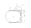
- FIG. 1 It is a figure which shows the state with which the head mounted display which concerns on Example 1 is mounted
- FIG. 12 is a flowchart showing “content display control process 2” for controlling display of content displayed by the emitting device of the head mounted display according to the second embodiment according to the eye movement of the left eye of the user.
- 14 is a flowchart showing “content display control process 3” for controlling display of content displayed by the emitting device of the head mounted display according to the third embodiment in accordance with the eye movements of both eyes of the user.
- FIG. 10 is an explanatory diagram illustrating an example of eye movement detected in the third embodiment.
- FIG. 10 is a block diagram illustrating an electrical configuration of a head mounted display according to a fourth embodiment.
- FIG. 10 is a flowchart illustrating “content display control process 4” for controlling display of content displayed by an emission device of a head mounted display according to a fourth embodiment according to an eyeball movement of a user's right eye.
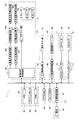
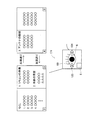
- FIG. It is a figure which shows an example of the relationship between the movement of the eyeball of a right eye, and the content (work procedure manual) displayed. It is a figure which shows an example of the relationship between the movement of the eyeball of a right eye, and the content (work procedure manual) displayed.
- the appearance of the head mounted display 1 shown in FIGS. 1 and 2 is merely an example, and the present invention is not limited to the head mounted display 1 having the appearance.
- an embodiment in which the present invention is applied to a retinal scanning display will be described.
- the present invention can be applied to various head mounted displays that perform image display using a liquid crystal element, an organic EL element, or the like.
- an embodiment in which the present invention is applied to an optical see-through head mounted display will be described.
- the present invention is a video see-through display as long as the head mounted display displays an image on one eye of a user.
- the present invention can also be applied to a type or external non-transparent type head mounted display.
- the head mounted display 1 receives various content information such as a moving image file, a still image file, and a document file (for example, a work procedure manual or a spreadsheet file) inputted from the outside as an image signal.
- the beam light (hereinafter referred to as “image light”) modulated according to the image signal is scanned on the retina of the left eye 5 of the user 2 (see FIGS. 4 and 6). Accordingly, an image corresponding to the content information (hereinafter referred to as “content”) can be visually recognized by the left eye 5 of the user 2 (see FIG. 4).
- the head-mounted display 1 has an external object 3 and a landscape in an area outside the area displaying the content in the field of view of the user 2 even when the content is being displayed. Etc. can be visually recognized. That is, the head-mounted display 1 is a see-through type head-mounted display that projects image light to the left eye 5 of the user 2 while transmitting outside light, that is, in a state where the outside is visible.
- the head mounted display 1 basically includes a CCD camera 7, a CCD camera 8, an emission device 11, a prism 12, and a support member 13 that supports them. It is configured.
- the CCD camera 7 images the left eye 5 of the user 2
- the CCD camera 8 images the right eye 6 (see FIG. 6) of the user 2.
- the emission device 11 emits image light Z1 to the left eye 5 of the user 2.
- the prism 12 reflects the image light Z1 toward the left eye 5 of the user 2.
- the prism 12 includes a beam splitter (not shown), transmits external light Z2 from the outside, and guides it to the left eye 5 of the user 2. In this manner, the prism 12 causes the image light Z1 incident from the side of the user 2 to enter the left eye 5 of the user 2 and causes the external light Z2 from the outside to enter the left eye 5 of the user 2. Therefore, the user 2 can visually recognize the content superimposed on the outside landscape.
- a beam splitter not shown
- the prism 12 can replace with the prism 12 and a half mirror can also be used. That is, the image light Z1 from the emitting device 11 is reflected by the half mirror and enters the left eye 5 of the user 2, and the external light Z2 passes through the half mirror and enters the user 2 eye.
- the CCD camera 7 includes CCD controllers 15 (see FIG. 3) that control the entire CCD camera 7 and a CCD sensor 16 (see FIG. 3) that captures the left eye 5 facing the CCD camera 7. Yes.
- the CCD camera 8 includes CCD controllers 17 (see FIG. 3) that control the entire CCD camera 8 and a CCD sensor 18 (see FIG. 3) that captures the right eye 6 facing the CCD camera 8. Yes.
- the CCD controller 15 stores the image captured by the CCD sensor 16 in the left eye image storage area of the RAM 53 of the control unit 36.
- the image stored in the left eye image storage area of the RAM 53 is subjected to image processing by the CPU 51, and the content is controlled to be displayed based on this image processing result as will be described later (see FIG. 5).
- the CCD controller 17 stores the image captured by the CCD sensor 18 in the right eye image storage area of the RAM 53 of the control unit 36.
- the image stored in the right-eye image storage area of the RAM 53 is subjected to image processing by the CPU 51.
- the start and end of content display that is, whether content display is on or off, based on the image processing result. It is controlled (see FIG. 5).
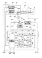
- FIG. 3 is a block diagram showing an electrical configuration of the head mounted display 1.
- the head mounted display 1 includes a CCD camera 7, a CCD camera 8, an emission device 11, an input unit 31, an external connection unit 32, a video RAM 34, a font ROM 35, and a control unit 36. And a power source unit 37 and the like.
- the CCD camera 7 images the left eye 5 of the user 2
- the CCD camera 8 images the right eye 6 of the user 2.
- the emission device 11 emits image light to the left eye 5 of the user 2.
- the input unit 31 inputs various operations and data.
- the external connection unit 32 receives content information from the outside.
- the video RAM 34 stores image data such as contents and text to be displayed by the emission device 11.
- the font data of the text displayed by the font ROM 35 emitting device 11 is stored.
- the control unit 36 controls the entire head mounted display 1. The details of the emission device 11 will be described later with reference to FIG.
- the CCD camera 7 includes a CCD controller 15 and a CCD sensor 16.
- the CCD controller 15 stores a captured image of the left eye 5 captured by the CCD sensor 16 in the left eye image storage area of the RAM 53 of the control unit 36.
- the CCD camera 8 includes a CCD controller 117, a CCD sensor 18, and the like.
- the CCD controller 17 captures an image of the right eye 6 captured by the CCD sensor 18 and stores a right-eye image storage area in the RAM 53 of the control unit 36.
- the input unit 31 includes an operation button group 41 including various function keys and an input control circuit 42.
- the input control circuit 42 detects that the key operation of the operation button group 41 has been performed, and outputs a control signal corresponding to the operated key to the control unit 36. For example, when an eye mouse start key (not shown) is operated, the input control circuit 42 controls a control signal that instructs to execute a program (see FIG. 5) of “content display control process 1” described later. To the unit 36. When an eye mouse stop key (not shown) is operated, the input control circuit 42 sends a control signal for instructing the control unit 36 to end execution of a program of “content display control processing 1” described later. Output.
- the external connection unit 32 includes an external connection module 45 that is connected to an external device (for example, a personal computer) and acquires content information, and an external connection control circuit 46. Then, the external connection control circuit 46 outputs the content information input from the external connection module 45 to the control unit 36, and the content information is stored in the flash memory 52.
- an external connection module 45 that is connected to an external device (for example, a personal computer) and acquires content information
- an external connection control circuit 46 outputs the content information input from the external connection module 45 to the control unit 36, and the content information is stored in the flash memory 52.
- the control unit 36 includes a CPU 51, a flash memory 52, a RAM 53, and the like, which are connected to each other via a bus line (not shown) and exchange data with each other.
- the CPU 51 is an arithmetic processing unit that controls the entire head mounted display 1 and manages all data related to the operation of the head mounted display 1. Further, the CPU 51 converts various content information into image signals and stores them in the video RAM 34. As will be described later, the CPU 51 captures images captured by the two eyes 5 and 6 of the user 2 captured by the CCD sensors 16 and 18 stored in the left eye image storage area and the right eye image storage area of the RAM 53. Processing is performed to detect the movement of each eyelid and eye movement, and display the content to be projected to the left eye 5 of the user 2 according to the detection result (see FIG. 5).
- the flash memory 52 stores various programs executed by the CPU 51. For example, the flash memory 52 performs a display control such as a left page return, a right page return, an up scroll, a down scroll, etc. according to the eye movement of the left eye 5 or the right eye 6 for content displayed on the head mounted display 1 described later. A control processing program for driving and controlling the emission device 11 is stored. The flash memory 52 stores content information input from the external connection control circuit 46.
- the various content information includes a work procedure manual (document file), a spreadsheet file, a moving image file, and the like. Further, part or all of the various programs may be stored in a read-only ROM (not shown).
- the RAM 53 temporarily stores captured images captured by the CCD sensors 16 and 18, and temporarily stores various data when the CPU 51 executes various controls.
- the video RAM 34 temporarily stores image signals.
- the image signal stored in the video RAM 34 is output to the video signal processing circuit 63 of the emission device 11 and projected onto the retina of the user 2 as content. Therefore, the CPU 51 can control the content to be displayed by reading the content information from the flash memory 52, converting the read content information into an image signal, and writing it into the video RAM 34.
- the power supply unit 37 includes a battery 56 and a charge control circuit 57.
- the battery 56 is a power source for driving the head mounted display 1.
- the charging control circuit 57 supplies the power of the battery 56 to the head mounted display 1 and supplies the power supplied from a charging adapter (not shown) to the battery 56 to charge the battery 56.
- the light emitting unit 11 is provided with a light source unit 61.
- the light source unit 61 generates image light based on the image signal input from the video RAM 34 and performs scanning control of the image light in the horizontal direction and the vertical direction based on the scanning control signal input from the CPU 51. .
- the light source unit 61 is provided with a video signal processing circuit 63.
- the video signal processing circuit 63 receives an image signal from the video RAM 34 and a scanning control signal from the CPU 51, and generates each signal as an element for synthesizing the video corresponding to the image signal. For example, the video signal processing circuit 63 outputs blue (B), green (G), and red (R) output control signals 65A to 65C, a horizontal synchronizing signal 66, and a vertical synchronizing signal 67 for each pixel.
- B blue
- G green
- R red
- the light source unit 61 is provided with a light source 71 and a light combiner 72.
- the light source unit 71 functions as an image light output unit that converts the three output control signals 65A to 65C output from the video signal processing circuit 63 for each dot clock into image light.
- the light combining unit 72 combines these three image lights into one image light to generate arbitrary image light.
- the light source unit 71 includes a B laser 74 that generates blue image light and a B laser driver 75 that drives the B laser 74 in accordance with the output control signal 65A.
- the light source unit 71 includes a G laser 76 that generates green image light and a G laser driver 77 that drives the G laser 76 in accordance with the output control signal 65B.
- the light source unit 71 includes an R laser 78 that generates red image light and an R laser driver 79 that drives the R laser 78 in accordance with the output control signal 65C.
- the lasers 74, 76, and 78 can be configured as, for example, a semiconductor laser or a solid-state laser with a harmonic generation mechanism. If a semiconductor laser is used, the drive current can be directly modulated to modulate the intensity of the image light. However, if a solid-state laser is used, each laser is equipped with an external modulator to modulate the intensity of the image light. Need to do.
- the light combining unit 72 includes collimating optical systems 81, 82, 83, dichroic mirrors 84, 85, 86, and a coupling optical system 87.
- Each of the collimating optical systems 81, 82, and 83 is provided so as to collimate the three image lights incident from the light source unit 71 into parallel lights.
- Each dichroic mirror 84, 85, 86 combines the three collimated image lights.
- the coupling optical system 87 guides the combined image light to the optical fiber 88.
- the laser beams emitted from the lasers 74, 76, and 78 are collimated by the collimating optical systems 81, 82, and 83, and then enter the dichroic mirrors 84, 85, and 86. Thereafter, the dichroic mirrors 84, 85, and 86 selectively reflect and transmit each image light with respect to the wavelength, reach the coupling optical system 87, collect the light, and enter the optical fiber 88.
- the emission device 11 includes a collimating optical system 89, a horizontal scanning unit 92, a vertical scanning unit 93, a relay optical system 94 provided between the horizontal scanning unit 92 and the vertical scanning unit 93, and relay optics.
- a system 96 is provided.
- the collimating optical system 89 collimates the image light generated by the light source unit 61 and emitted through the optical fiber 88 into parallel light.
- the horizontal scanning unit 92 reciprocally scans the image light collimated by the collimating optical system 89 in the horizontal direction.
- the vertical scanning unit 93 scans the image light that has been reciprocated in the horizontal direction by the horizontal scanning unit 92 in the vertical direction.
- the relay optical system 96 emits the image light thus scanned in the horizontal direction and the vertical direction (two-dimensionally scanned) to the pupil 95 of the left eye 5 of the user 2.
- the prism 12 is disposed between the relay optical system 96 and the pupil 95 of the user 2 and guides the image light emitted from the emission device 11 to the pupil 95 of the user 2 by totally reflecting the light.
- the horizontal scanning unit 92 is provided with a resonant deflection element 101, a horizontal scanning control circuit 102, and a horizontal scanning angle detection circuit 103.
- the resonant deflection element 101 has a reflective surface 101A for reciprocally scanning image light in the horizontal direction.
- the horizontal scanning control circuit 102 performs drive control based on the horizontal synchronizing signal 66 input from the video signal processing circuit 63 so as to resonate the resonance type deflection element 101 and swing the reflecting surface 101A.
- the horizontal scanning angle detection circuit 103 detects a swinging state such as a swinging angle and a swinging frequency of the resonant deflection element 101.
- the vertical scanning unit 93 is provided with a deflection element 105, a vertical scanning control circuit 106, and a vertical scanning angle detection circuit 107.
- the deflection element 105 has a reflection surface 105A for scanning image light in the vertical direction.
- the vertical scanning control circuit 106 drives and controls the deflection element 105 to swing the reflecting surface 105A.
- the vertical scanning angle detection circuit 107 detects a swing state such as a swing angle and a swing frequency of the deflection element 105.
- the horizontal scanning angle detection circuit 103 outputs a swing signal 104 indicating the detected swing state of the resonance type deflection element 101 to the CPU 51.
- the vertical scanning angle detection circuit 107 outputs a swing signal 108 indicating the detected swing state of the deflection element 105 to the CPU 51.
- the CPU 51 determines a scanning control signal to be output to the video signal processing circuit 63 based on the received swing signals 104 and 108.
- the drive states of the resonant deflection element 101 and the deflection element 105 are feedback controlled by the CPU 51.
- the swing signals 104 and 108 may be output to the video signal processing circuit 63.
- the video signal processing circuit 63 may be configured to output the horizontal synchronization signal 66 and the vertical synchronization signal 67 based on the swing signals 104 and 108. That is, the drive state of the resonance type deflection element 101 and the deflection element 105 may be feedback controlled by the video signal processing circuit 63.
- the light scanned in the horizontal direction by the resonant deflection element 101 is converged on the reflection surface 105 A of the deflection element 105 by the relay optical system 94 provided between the horizontal scanning unit 92 and the vertical scanning unit 93. Then, the converged light is scanned in the vertical direction by the deflecting element 105 and is emitted to the relay optical system 96 as scanned image light scanned two-dimensionally.
- the relay optical system 96 converts the display scanning image light emitted from the vertical scanning unit 93 into substantially parallel image light, and converges the center line of these image light to the pupil 95 of the user 2. Convert to
- the arrangement of the horizontal scanning unit 92 and the vertical scanning unit 93 is switched, and the image light incident from the optical fiber 88 is scanned in the vertical direction by the vertical scanning unit 93 and then scanned in the horizontal direction by the horizontal scanning unit 92. You may do it.
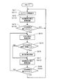
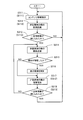
- the program shown in the flowchart of FIG. 5 is stored in the flash memory 52 of the control unit 36, and a control signal corresponding to an operation of an eye mouse start key (not shown) included in the operation button group 41 is input to the input control circuit.
- a control signal corresponding to an operation of an eye mouse start key (not shown) included in the operation button group 41 is input to the input control circuit.
- it is executed by the CPU 51.
- the program shown in the flowchart of FIG. 5 is obtained when a control signal corresponding to an operation of an eye mouse stop key (not shown) included in the operation button group 41 is input from the input control circuit 42 to the control unit 36. The execution is terminated by the CPU 51.
- the image signals captured by the CCD sensors 16 and 18 are respectively stored in the left eye image storage area and the right eye image storage area of the RAM 53 at predetermined frame rates. (For example, about 30 frames per second). It is assumed that content information to be displayed is stored in advance in the flash memory 52. In addition, when a plurality of pieces of content information are stored in the flash memory 52, it is assumed that which content information is to be displayed is set in advance.
- step (hereinafter abbreviated as “S”) 11 the CPU 51 inputs contents such as a work procedure manual (document file) input from the external connection control circuit 46 and stored in the flash memory 52. If there is information, the content information is read out, converted into an image signal, and stored in the video RAM 34. Thereby, an image signal is input from the video RAM 34 to the video signal processing unit 63, and content (image) corresponding to the content information is displayed on the left eye 5 of the user 2 via the emission device 11.
- contents such as a work procedure manual (document file) input from the external connection control circuit 46 and stored in the flash memory 52. If there is information, the content information is read out, converted into an image signal, and stored in the video RAM 34. Thereby, an image signal is input from the video RAM 34 to the video signal processing unit 63, and content (image) corresponding to the content information is displayed on the left eye 5 of the user 2 via the emission device 11.
- the content information is a work procedure manual (document file)
- the content corresponding to the first page see FIG. 8
- the first and second pages in the spread state see FIG. 9
- the image is displayed on the left eye 5 of the user 2 via the emission device 11.
- the CPU 51 recognizes the image data stored in the right eye image storage area of the RAM 53, that is, the image data of the right eye 6 of the user 2 by a predetermined number of frames (for example, about 30 frames). To do. Then, the CPU 51 stores, in the RAM 53, image recognition data for a predetermined number of frames of the right eye 6 of the user 2, that is, the right eye 6 on the side where the emission device 11 is not attached.
- image recognition when white and black eyes (pupil colors) of the eyeball are detected, it is recognized that the eyelid is not closed, while the white and black eyes of the eyeball are detected. If the skin color is mainly detected, it is recognized that the eyelid is closed.
- the CPU 51 reads image recognition data for a predetermined number of frames of the right eye 6 of the user 2 from the RAM 53, and whether or not the eyelid 6A (see FIG. 6) of the right eye 6 is continuously closed.
- a determination process for determining Specifically, the CPU 51 reads image recognition data for a predetermined number of frames of the right eye 6, and when the eyeball of the right eye 6 is not detected, that is, when skin color is mainly detected, the eyelid 6A is closed. Is determined.
- the CPU 51 recognizes the image data stored in the left eye image storage area of the RAM 53, that is, the image data of the left eye 5 of the user 2 by a predetermined number of frames (for example, about 30 frames). Then, the CPU 51 stores in the RAM 53 image recognition data for a predetermined number of frames of the left eye 5 of the user 2, that is, the left eye 5 on which the emission device 11 is attached.
- the CPU 51 reads out image recognition data for a predetermined number of frames of the left eye 5 of the user 2 from the RAM 53 and determines whether or not the eyeball 5 ⁇ / b> A (see FIG. 6) of the left eye 5 has moved. Execute the process.
- the CPU 51 detects the moving direction of the eyeball 5A, that is, the moving direction of the pupil of the eyeball 5A, from the image recognition data for the predetermined number of frames of the left eye 5 captured by the CCD camera 7.
- the CPU 51 determines that the eyeball 5A has moved in that direction.
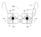
- the movement direction is stored in the RAM 53 as the movement direction of the eyeball 5A. Note that the CPU 51 determines that the eyeball 5A has moved in each direction when the pupil of the eyeball 5A moves in the upward direction 121, the downward direction 122, the left direction 123, or the right direction 124 from the center position of the white eye.
- the CPU 51 determines that the eyeball 5A has not moved. To do.
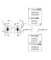
- FIG. 9 An example in which content (image) display control is performed based on the content of the control table 131 stored in advance in the flash memory 52 will be described with reference to FIGS.
- the spread page display (display for two pages) is used, but it goes without saying that a single page may be displayed.
- the second half of the third page and the first half of the fourth page is displayed.
- the entire third page is displayed.
- the scroll amount can be a predetermined number of rows / columns.
- the CPU 51 may recognize the moving speed of the eyeball 5A and determine the scroll amount according to the recognized speed.
- the fourth page and the fifth page are displayed. Is displayed.
- the eyeball 5A of the left eye 5 is moved in the left direction 123 while the fourth page and the fifth page are displayed, the second page and the third page are displayed.
- the eyeball 5A of the left eye 5 is in the upward direction 121, the downward direction 122, the leftward direction 123, or the right in S15.
- the CPU 51 operates on the content (image) being displayed. , “Up scroll”, “Down scroll”, “Left scroll” or “Right scroll”, respectively.
- the CPU 51 returns the playback position of the moving image file.
- the playback position return / advance amount can be one chapter or a predetermined time (for example, about 30 seconds).
- the CPU 51 may recognize the moving speed of the eyeball 5A and determine the return / advance amount of the reproduction position according to the recognized speed.
- the CPU 51 recognizes an image captured by the right eye 6 captured by the CCD sensor 18.
- the CPU 51 recognizes the captured image of the left eye 5 captured by the CCD sensor 16 and projects the content (image). The moving direction of the moving eyeball 5A is detected.
- the CPU 51 performs display control such as upward scrolling and downward scrolling of the content (image) based on the upward movement 121, the downward direction 122, the leftward direction 123, or the rightward direction 124 of the eyeball 5A.
- display control such as upward scrolling and downward scrolling of the content (image) based on the upward movement 121, the downward direction 122, the leftward direction 123, or the rightward direction 124 of the eyeball 5A.
- the user 2 moves the line of sight of the left eye 5 in the upward direction 121, the downward direction 122, the left direction 123, or the right direction 124 by closing the right eye 6 on which no content is projected. It is possible to scroll and display the page (page) of content (image) such as the displayed work procedure manual in the vertical and horizontal directions, and to change the playback position of the moving image displayed on the left eye 5. .
- the eye 6A of the right eye 6 is closed, and the gaze direction of the left eye 5 is the upward direction 121, the downward direction 122, the left direction 123, or the right direction 124.
- the content (image) can be manipulated by moving it to, and work efficiency can be improved.
- FIG. 1 when a work procedure manual relating to the object 3 is displayed on the head mounted display 1, the line of sight of the left eye 5 is moved up and down or left and right while handling the object 3 with both hands.
- a predetermined page such as a work procedure manual can be displayed.
- the user 2 moves the line of sight of the left eye 5 up and down or left and right only while closing the eyelid 6 ⁇ / b> A of the right eye 6, and manipulates the display state of the content (image) visually recognized by the left eye 5.
- the CPU 51 can accurately distinguish the operation of the eyelid 6A of the right eye 6 from the physiological blink, and can prevent the malfunction of the head mounted display 1.
- the CPU 51 can distinguish between the physiological movement of the left eye 5 and the movement when the eyeball 5A is moved for operation by opening / closing the eyelid 6A of the right eye 6, the physiological movement of the left eye 5 can be distinguished. It is possible to prevent malfunction of the head mounted display 1 due to the above.
- the head mounted display 151 according to the second embodiment will be described with reference to FIG.
- the same reference numerals as those of the head mounted display 1 according to the first embodiment denote the same or corresponding parts as those of the head mounted display 1 according to the first embodiment.
- the schematic configuration of the head mounted display 151 according to the second embodiment is the same as that of the head mounted display 1 according to the first embodiment.
- Various control processes of the head mounted display 151 are substantially the same control processes as those of the head mounted display 1 according to the first embodiment.
- the CPU 51 of the head mounted display 151 is different in that, instead of the “content display control process 1” (S11 to S16), a “content display control process 2” described later is executed.
- Content display control process 2 it is a process executed by the CPU 51 of the head mounted display 151 according to the second embodiment, and the content (image) displayed by the emission device 11 is displayed and controlled according to the eye movement of the left eye 5 of the user 2
- the “display control process 2” will be described with reference to FIG.
- the CPU 51 executes the same processing (see FIG. 5) as in S11 through S12. However, in S112, the CPU 51 stores, in the RAM 53, image recognition data for the number of frames corresponding to a predetermined time (for example, about 2 seconds) of the right eye 6 on the side on which the emission device 11 is not mounted.
- a predetermined time for example, about 2 seconds
- the CPU 51 stores the image recognition data for the number of frames (for example, about 60 frames) corresponding to the predetermined time (for example, about 2 seconds) of the right eye 6 of the user 2 from the RAM 53. Whether or not the eyelid 6A of the right eye 6 is continuously opened after being closed for a predetermined number of frames (for example, about 30 frames) for a predetermined time (for example, about 1 second). A determination process is performed to determine whether or not.
- the CPU 51 executes the processing after S111 again.
- the CPU 51 executes the same processing as in S112 to S113.
- the eyelid 6A of the right eye 6 is not continuously opened after being closed for a predetermined number of frames (for example, about 30 frames) for a predetermined time (for example, about 1 second).
- a predetermined number of frames for example, about 30 frames
- a predetermined time for example, about 1 second.
- the CPU 51 executes the processes after S114 again.
- the CPU 51 recognizes an image captured by the right eye 6 captured by the CCD sensor 18. Then, the CPU 51 opens the eye 6A of the right eye 6 continuously after being closed for a predetermined number of frames (for example, about 30 frames) for a predetermined time (for example, about 1 second). In other words, the CPU 51 recognizes the captured image of the left eye 5 captured by the CCD sensor 16 and detects the moving direction of the eyeball 5A on which the content (image) is projected. Note that the CPU 51 determines that the eyeball 5A has moved in each direction when the pupil of the eyeball 5A moves in the upward direction 121, the downward direction 122, the left direction 123, or the right direction 124 from the center position of the white eye.
- the CPU 51 performs display control such as upward scrolling and downward scrolling of the content (image) based on the upward movement 121, the downward direction 122, the leftward direction 123, or the rightward direction 124 of the eyeball 5A.
- display control such as upward scrolling and downward scrolling of the content (image) based on the upward movement 121, the downward direction 122, the leftward direction 123, or the rightward direction 124 of the eyeball 5A.
- the user 2 closes the eyelid 6A of the right eye 6 on which the content is not projected for a predetermined time (for example, about 1 second) and then opens the eyeline direction of the left eye 5 upward 121,
- a predetermined time for example, about 1 second
- the contents (images) such as the work procedure manual displayed on the left eye 5 are scroll-displayed or paged in the vertical direction or the horizontal direction, It is possible to change the playback position of the moving image displayed in FIG.
- the user 2 again closes the eyelid 6A of the right eye 6 on which no content is projected for a predetermined time (for example, about 1 second) and then opens it, thereby changing the line-of-sight direction of the left eye 5. It is possible to cancel scroll display and page turning of contents (images) such as work procedure manuals. For this reason, it becomes possible to prevent the change in the display state of the content (image) due to the change in the viewing direction of the left eye 5 unnecessary for the user 2.
- a predetermined time for example, about 1 second
- the eye 6 of the right eye 6 is closed after being closed for a predetermined time (for example, about 1 second), and then the line of sight of the left eye 5 is opened.
- the content (image) can be manipulated by moving the direction in the upward direction 121, the downward direction 122, the left direction 123, or the right direction 124, and work efficiency can be improved.
- FIG. 1 when a work procedure manual relating to the object 3 is displayed on the head mounted display 151, the line of sight of the left eye 5 is moved up and down or left and right while handling the object 3 with both hands.
- a predetermined page such as a work procedure manual can be displayed.
- the user 2 again closes the eyelid 6A of the right eye 6 for a predetermined time (for example, about 1 second) and then opens it, thereby canceling the operation of the content (image) according to the line-of-sight direction of the left eye 5. It is possible to change the line-of-sight direction of both eyes 5 and 6 with a predetermined page such as a work procedure manual opened.
- the user 2 closes the eyelid 6A of the right eye 6 for a predetermined time (for example, about 1 second) and then opens the left eye 5 to move the line of sight of the left eye 5 up and down or left and right. It becomes possible to manipulate the display state of the content (image) being viewed. Further, the CPU 51 can accurately distinguish the operation of the eyelid 6A of the right eye 6 from the physiological blink, and can prevent the malfunction of the head mounted display 151.
- a predetermined time for example, about 1 second
- the CPU 51 can accurately distinguish the operation of the eyelid 6A of the right eye 6 from the physiological blink, and can prevent the malfunction of the head mounted display 151.
- the head mounted display 161 according to the third embodiment will be described with reference to FIGS.
- the same reference numerals as those of the head mounted display 1 according to the first embodiment denote the same or corresponding parts as those of the head mounted display 1 according to the first embodiment.
- the schematic configuration of the head mounted display 161 according to the third embodiment is the same as that of the head mounted display 1 according to the first embodiment.
- Various control processes of the head mounted display 161 are substantially the same control processes as those of the head mounted display 151 according to the second embodiment.
- the CPU 51 of the head mounted display 161 displays and controls the content (image) described later according to the eye movements of the two eyes 5 and 6 of the user 2 instead of the “content display control process 2” (S111 to S118). The difference is that the “content display control process 3” is executed.
- Content display control process 3 it is a process executed by the CPU 51 of the head mounted display 161 according to the third embodiment, and the display of the content (image) displayed by the emitting device 11 is controlled according to the eye movements of the two eyes 5 and 6 of the user 2. “Content display control process 3” will be described with reference to FIGS.
- the program shown in the flowchart of FIG. 11 is stored in the flash memory 52 of the control unit 36, and a control signal corresponding to the operation of an eye mouse start key (not shown) included in the operation button group 41 is input to the input control circuit.
- a control signal corresponding to the operation of an eye mouse start key (not shown) included in the operation button group 41 is input to the input control circuit.
- the program shown in the flowchart of FIG. 11 is executed when a control signal corresponding to an operation of an eye mouse stop key (not shown) included in the operation button group 41 is input from the input control circuit 42 to the control unit 36. The execution is terminated by the CPU 51.
- the CPU 51 executes the same processing (see FIG. 10) as in S111 through S113.
- the CPU 51 determines that the eyelid 6A of the right eye 6 is not closed for a predetermined number of frames (for example, about 30 frames) for a predetermined time (for example, about 30 frames), that is, If the eyelid 6A of the eye 6 has not been closed for a predetermined time or has been closed in a blink (S213: NO), the processing after S211 is executed again.
- the CPU 51 stores image recognition data for the number of frames corresponding to a predetermined time (for example, about 2 seconds) of the right eye 6 on the side where the emission device 11 is not mounted in the RAM 53.
- step S213 the CPU 51 opens the eye 6A of the right eye 6 continuously after the number of frames (for example, about 30 frames) for a predetermined time (for example, about 1 second) is closed. If yes (S213: YES), the process proceeds to S214.
- the CPU 51 recognizes each image data of the same timing stored in the left eye image storage area and the right eye image storage area of the RAM 53 by a predetermined number of frames (for example, about 30 frames), and the user. Image recognition data for a predetermined number of frames at the same timing of the two eyes 5 and 6 is stored in the RAM 53.
- the CPU 51 reads out the image recognition data for the predetermined number of frames at the same timing of the two eyes 5 and 6 of the user 2 from the RAM 53, and each eyeball 5A and 6B of both eyes 5 and 6 (FIG. 12). A determination process for determining whether or not (see) has moved at the same time is executed.
- the CPU 51 determines the moving direction of each eyeball 5 ⁇ / b> A, 6 ⁇ / b> B from the image recognition data for a predetermined number of frames at the same timing of both eyes 5, 6 captured by the CCD cameras 7, 8. That is, the moving direction of the pupil of each eyeball 5A, 6B is detected.
- the CPUs 5A and 6B move in the respective directions. Judge that it has moved.
- the CPU 51 determines that each of the eyeballs 5A and 6B. Are simultaneously moved in that direction, and this moving direction is stored in the RAM 53 as the moving direction of each eyeball 5A, 6B.
- the CPU 51 , 6B are determined not to move at the same time.
- the CPU 51 proceeds to the process of S216.
- the CPU 51 performs display control of content (image) based on the content of the control table 131 (see FIG. 7) stored in advance in the flash memory 52, and then proceeds to the processing of S217.
- the scroll amount can be a predetermined number of rows / columns.
- the moving speed of each eyeball 5A, 6B may be recognized, and the scroll amount may be determined according to the recognized speed.
- the fourth page The eyes and the fifth page are displayed.
- the 4th page and the 5th page are displayed and the respective eyeballs 5A and 6B of both eyes 5 and 6 are simultaneously moved in the left direction 123, the 2nd page and the 3rd page are displayed. Is displayed.
- the CPU 51 may recognize the moving speed of each of the eyeballs 5A and 6B, and determine the return / advance amount of the reproduction position according to the recognized speed. As a result, the user 2 can always recognize the moving image with the left eye 5 on the wearing side even if the non-wearing right eye 6 is closed for a certain period of time in order to start the operation. , Can do the appropriate operation.
- step S2108 the CPU 51 determines that the eyelid 6A of the right eye 6 is not closed for a predetermined number of frames (for example, about 30 frames) for a predetermined time (for example, about 30 frames), that is, If the eyelid 6A of the eye 6 has not been closed for a predetermined time or has been closed by blinking (S218: NO), the processing after S214 is executed again.
- a predetermined number of frames for example, about 30 frames
- a predetermined time for example, about 30 frames
- the eyelid 6A of the right eye 6 is continuously opened after being closed for a predetermined number of frames (for example, about 30 frames) for a predetermined time (for example, about 1 second).
- a predetermined number of frames for example, about 30 frames
- a predetermined time for example, about 1 second.
- the CPU 51 recognizes an image captured by the right eye 6 captured by the CCD sensor 18. Then, the CPU 51 indicates that the eye 6A of the right eye 6 is continuously opened after being closed for a predetermined number of frames (for example, about 30 frames) for a predetermined time (for example, about 1 second). In the case of recognition, the captured images of both eyes 5 and 6 imaged by the CCD sensors 16 and 18 are image-recognized, and the moving directions of the eyeballs 5A and 6B of both eyes 5 and 6 are detected.
- the CPU 51 then scrolls up and down the content (image) projected to the left eye 5 based on the movement in the upward direction 121, the downward direction 122, the left direction 123, or the right direction 124 of each eyeball 5A, 6B. Display control.
- the CPU 51 recognizes that the eyelid 6A of the right eye 6 is continuously opened after being closed for a predetermined number of frames, the CPU 51 ends the detection of the moving direction of each eyeball 5A, 6B. Then, the display control by the movement of each eyeball 5A, 6B of the content (image) is terminated and normal content display is performed.
- the user 2 closes the eyelid 6A of the right eye 6 on which no content is projected for a predetermined time (for example, about 1 second), and then opens the eyes, thereby simultaneously increasing the line-of-sight directions of both eyes 5 and 6.
- a predetermined time for example, about 1 second
- the user 2 closes the eyelid 6A of the right eye 6 on which no content is projected for a predetermined time (for example, about 1 second), and then opens the eyes, thereby simultaneously increasing the line-of-sight directions of both eyes 5 and 6.
- the playback position of the moving image displayed on the left eye 5 can be changed.
- the user 2 again closes the eyelid 6A of the right eye 6 on which no content is projected for a predetermined time (for example, about 1 second), and then opens the eye 6A in the line-of-sight direction of both eyes 5 and 6. It becomes possible to cancel scroll display and page feed of contents (images) such as work procedure manuals due to the change. Then, the user 2 can prevent a change in the display state of the content (image) due to an unnecessary change in the viewing direction.
- a predetermined time for example, about 1 second
- the eyes 6A of the right eye 6 are closed for a predetermined time (for example, about 1 second) and then opened to open the eyes 5 and 6.
- the content (image) can be manipulated by simultaneously moving the visual line direction in the upward direction 121, the downward direction 122, the left direction 123, or the right direction 124, thereby improving work efficiency.
- a predetermined page such as a work procedure manual can be displayed.
- the user 2 again operates the content (image) according to the line-of-sight direction of both eyes 5 and 6 by closing and opening the eyelid 6A of the right eye 6 for a predetermined time (for example, about 1 second).
- a predetermined time for example, about 1 second.
- the user 2 closes the eyelid 6A of the right eye 6 for a predetermined time (for example, about 1 second) and then opens it to move the eyes of both eyes 5 and 6 simultaneously up and down or left and right. It becomes possible to manipulate the display state of the content (image) visually recognized by the eye 5. Further, the CPU 51 can accurately distinguish the operation of the eyelid 6A of the right eye 6 from the physiological blink, and can prevent the malfunction of the head mounted display 161.
- a predetermined time for example, about 1 second
- the CPU 51 can accurately distinguish the operation of the eyelid 6A of the right eye 6 from the physiological blink, and can prevent the malfunction of the head mounted display 161.
- a head mounted display 171 according to the fourth embodiment will be described with reference to FIGS.
- the same reference numerals as those of the head mounted display 1 according to the first embodiment denote the same or corresponding parts as those of the head mounted display 1 according to the first embodiment.
- the schematic configuration of the head mounted display 171 according to the fourth embodiment is substantially the same as the head mounted display 1 (see FIG. 1) according to the first embodiment.
- the head mounted display 171 is different from the head mounted display 1 according to the first embodiment in that the CCD camera 7 for imaging the left eye 5 of the user 2 is not provided.
- the head mounted display 171 includes a CCD camera 8, an output device 11, an input unit 31, an external connection unit 32, a video RAM 34, a font ROM 35, a control unit 36, a power source, and the like. Part 37 and the like.
- the CCD camera 8 images the right eye 6 of the user 2.
- the emission device 11 emits image light to the left eye 5 of the user 2.
- the input unit 31 inputs various operations and data.
- the external connection unit 32 receives content information from the outside.
- the video RAM 34 stores image data such as contents and text to be displayed by the emission device 11.
- the font data of the text displayed by the font ROM 35 emitting device 11 is stored.
- the control unit 36 controls the entire head mounted display 1.
- control processes of the head mounted display 171 are substantially the same control processes as those of the head mounted display 151 according to the second embodiment.
- the CPU 51 of the head mounted display 171 replaces the “content display control process 2” (S111 to S118) with the content (image) described later according to the eye movement of the right eye 6 of the user 2 “content display”. The difference is that the control process 4 "is executed.
- Content display control process 4 “contents” is processing executed by the CPU 51 of the head mounted display 171 according to the fourth embodiment, and displays and controls content (images) displayed by the emission device 11 according to the eye movement of the right eye 6 of the user 2.
- the “display control process 4” will be described with reference to FIGS.
- the program shown in the flowchart in FIG. 17 is stored in the flash memory 52 of the control unit 36, and a control signal corresponding to the operation of an eye mouse start key (not shown) included in the operation button group 41 is input to the input control circuit.
- a control signal corresponding to the operation of an eye mouse start key (not shown) included in the operation button group 41 is input to the input control circuit.
- it is executed by the CPU 51.
- the program shown in the flowchart of FIG. 17 is obtained when a control signal corresponding to an operation of an eye mouse stop key (not shown) included in the operation button group 41 is input from the input control circuit 42 to the control unit 36. The execution is terminated by the CPU 51.
- the CPU 51 executes the same processing (see FIG. 10) as in S111 to S113.
- the CPU 51 determines that the eyelid 6A of the right eye 6 is not closed for a predetermined number of frames (for example, about 30 frames) for a predetermined time (for example, about 30 frames), that is, When the eyelid 6A of the eye 6 has not been closed for a predetermined time or has been closed by blinking (S313: NO), the processing after S311 is executed again.
- the CPU 51 stores, in the RAM 53, image recognition data for the number of frames corresponding to a predetermined time (for example, about 2 seconds) of the right eye 6 on the side where the emission device 11 is not mounted.
- the CPU 51 continuously opens after the eyelid 6A of the right eye 6 is closed for the number of frames (for example, about 30 frames) for a predetermined time (for example, about 1 second). If yes (S313: YES), the process proceeds to S314. In S314, the CPU 51 recognizes the image data stored in the right eye image storage area of the RAM 53 by a predetermined number of frames (for example, about 30 frames), and the right eye 6 of the user 2, that is, the emission device.
- the RAM 53 stores image recognition data for a predetermined number of frames of the right eye 6 on the side on which the 11 is not attached.
- the CPU 51 reads out image recognition data for a predetermined number of frames of the right eye 6 of the user 2 from the RAM 53, and determines whether or not the eyeball 6B (see FIG. 18) of the right eye 6 has moved. Execute the process. Note that the CPU 51 determines that the eyeball 6B has moved in each direction when the pupil of the eyeball 6B moves in the upward direction 121, the downward direction 122, the left direction 123, or the right direction 124 from the center position of the white eye.
- the CPU 51 detects the moving direction of the eyeball 6B, that is, the moving direction of the pupil of the eyeball 6B, from the image recognition data for the predetermined number of frames of the right eye 6 captured by the CCD camera 8.
- the CPU 51 determines that the eyeball 6B has moved in that direction.
- the moving direction is stored in the RAM 53 as the moving direction of the eyeball 6B.
- the CPU 51 determines that the eyeball 6B has not moved. To do.
- the second half of the third page and the first half of the fourth page Is displayed.
- the eyeball 6B of the right eye 6 is moved in the upward direction 121 in a state where the second half of the third page and the first half of the fourth page are displayed, the entire third page is displayed.
- the scroll amount can be a predetermined number of rows / columns. Further, the moving speed of the eyeball 6B may be recognized, and the scroll amount may be determined according to the recognized speed.
- the fourth and fifth pages are displayed. Is displayed.
- the eyeball 6B of the right eye 6 is moved in the left direction 123 while the fourth and fifth pages are displayed, the second and third pages are displayed.
- the eyeball 6B of the right eye 6 is up 121, down 122, left 123 or right in S315.
- the CPU 51 operates on the content (image) being displayed. , “Up scroll”, “Down scroll”, “Left scroll” or “Right scroll”, respectively.
- the CPU 51 returns the playback position of the moving image file.
- the eyeball 6B of the right eye 6 moves in the right direction 124, that is, when it moves “to the right”
- the CPU 51 advances the reproduction position of the moving image file.
- the playback position return / advance amount can be one chapter or a predetermined time (for example, about 30 seconds).
- the CPU 51 may recognize the moving speed of the eyeball 6B and determine the return / advance amount of the reproduction position according to the recognized speed. As a result, the user 2 can always recognize the moving image with the left eye 5 on the wearing side even if the non-wearing right eye 6 is closed for a certain period of time in order to start the operation. , Can do the appropriate operation.
- the CPU 51 executes the same processing as in S312 to S313.
- the CPU 51 determines that the eyelid 6A of the right eye 6 is not closed for a predetermined number of frames (for example, about 30 frames) for a predetermined time (for example, about 30 frames), that is, If the eyelid 6A of the eye 6 has not been closed for a predetermined time or has been closed by blinking (S318: NO), the processing after S314 is executed again.
- the eyelid 6A of the right eye 6 is continuously opened after being closed for a predetermined number of frames (for example, about 30 frames) for a predetermined time (for example, about 1 second).
- a predetermined number of frames for example, about 30 frames
- a predetermined time for example, about 1 second.
- the CPU 51 recognizes an image captured by the right eye 6 captured by the CCD sensor 18. Then, the CPU 51 opens the eye 6A of the right eye 6 continuously after being closed for a predetermined number of frames (for example, about 30 frames) for a predetermined time (for example, about 1 second). In this case, the captured image of the right eye 6 captured by the CCD sensor 18 is recognized as an image, and the moving direction of the eyeball 6B of the right eye 6 is detected.
- the CPU 51 then displays the content (image) projected on the left eye 5 based on the movement in the upward direction 121, the downward direction 122, the left direction 123, or the right direction 124 of the eyeball 6B. Take control.
- the CPU 51 ends the detection of the moving direction of the eyeball 6B of the right eye 6, Display control by moving the eyeball 6B of the content (image) projected to the left eye 5 is terminated and normal content display is performed.
- the user 2 closes the eyelid 6A of the right eye 6 on which the content is not projected for a predetermined time (for example, about 1 second), and then opens the eye 6 so that the line-of-sight direction of the right eye 6 is the upward direction 121,
- a predetermined time for example, about 1 second
- the contents (images) such as the work procedure manual displayed on the left eye 5 are scroll-displayed or paged in the vertical direction or the horizontal direction, It is possible to change the playback position of the moving image displayed in FIG.
- the user 2 again closes the eyelid 6A of the right eye 6 on which no content is projected for a predetermined time (for example, about 1 second) and then opens it, thereby changing the line-of-sight direction of the right eye 6. It is possible to cancel scroll display and page turning of contents (images) such as work procedure manuals. Then, the user 2 can prevent an unnecessary change in the display state of the content (image) due to a change in the viewing direction of the right eye 6.
- a predetermined time for example, about 1 second
- the user's line of sight of the right eye 6 is opened by closing the eyelid 6A of the right eye 6 for a predetermined time (for example, about 1 second) and then opening it.
- the content (image) can be manipulated by moving the direction in the upward direction 121, the downward direction 122, the left direction 123, or the right direction 124, and work efficiency can be improved.
- FIG. 15 when a work procedure manual or the like related to the object 3 is displayed on the head mounted display 171, the line of sight of the right eye 6 is moved up and down or left and right while handling the object 3 with both hands.
- a predetermined page such as a work procedure manual can be displayed.
- the user 2 again closes the eyelid 6 ⁇ / b> A of the right eye 6 for a predetermined time (for example, about 1 second), and then opens it to stop the operation of the content (image) according to the line-of-sight direction of the right eye 6. It is possible to change the line-of-sight direction of both eyes 5 and 6 with a predetermined page such as a work procedure manual opened.
- the user 2 closes the eyelid 6A of the right eye 6 for a predetermined time (for example, about 1 second) and then opens the eye 6 to move the line of sight of the right eye 6 up and down or left and right. It becomes possible to manipulate the display state of the content (image) being viewed. Further, the CPU 51 can accurately distinguish the operation of the eyelid 6A of the right eye 6 from the physiological blink, and can prevent the malfunction of the head mounted display 171.
- a predetermined time for example, about 1 second
- the CPU 51 can accurately distinguish the operation of the eyelid 6A of the right eye 6 from the physiological blink, and can prevent the malfunction of the head mounted display 171.
- the present invention is not limited to the first to fourth embodiments, and various improvements and modifications can be made without departing from the gist of the present invention. For example, the following may be used.
- the emission device 11 of the head mounted display 1 may be attached to the right eye 6 side.
- the CPU 51 determines whether or not the eyelid of the left eye 5 is closed based on the image data stored in the left eye image storage area of the RAM 53. Also good.
- the CPU 51 determines the eyeball 6B of the right eye 6 based on the image data stored in the right eye image storage area of the RAM 53. Based on the movement in the upward direction 121, the downward direction 122, the left direction 123, or the right direction 124, display control such as upward scrolling and downward scrolling of the content (image) displayed on the right eye 6 may be performed. .
- the emission device 11 of the head mounted display 151 may be attached to the right eye 6 side.
- the number of frames for which the eyelid of the left eye 5 is a predetermined time (for example, about 1 second). After being closed (for example, about 30 frames), it may be determined whether or not it is continuously opened.
- the CPU 51 stores image recognition data for the number of frames corresponding to a predetermined time (for example, about 2 seconds) of the left eye 5 on the side where the emission device 11 is not mounted in the RAM 53.
- the CPU 51 continues after the eyelid of the left eye 5 is closed for a predetermined number of frames (for example, about 30 seconds) for a predetermined time (for example, about 30 seconds). If it is opened, the image data stored in the right eye image storage area of the RAM 53 is moved in the upward direction 121, the downward direction 122, the left direction 123, or the right direction 124 of the eye 6B of the right eye 6. Based on the above, display control such as up-scrolling and down-scrolling of the content (image) displayed on the right eye 6 may be performed.
- the emission device 11 of the head mounted display 161 may be attached to the right eye 6 side.
- the number of frames in which the eyelid of the left eye 5 is a predetermined time (for example, about 1 second). After being closed (for example, about 30 frames), it may be determined whether or not it is continuously opened.
- the CPU 51 stores, in the RAM 53, image recognition data for the number of frames corresponding to a predetermined time (for example, about 2 seconds) of the left eye 5 on the side where the emission device 11 is not attached.
- the CPU 51 continues after the eyelid of the left eye 5 is closed for the number of frames (for example, about 30 frames) for a predetermined time (for example, about 1 second).
- the upward direction 121 is determined from the image data stored in the left-eye image storage area and the right-eye image storage area of the RAM 53. Based on the movement in the downward direction 122, the left direction 123, or the right direction 124, display control such as upward scrolling and downward scrolling of the content (image) displayed on the right eye 6 may be performed.
- the emission device 11 of the head mounted display 171 may be attached to the right eye 6 side.
- the CCD camera 7 that images the left eye 5 of the user 2 may be provided, and the CCD camera 8 that images the right eye 6 may not be provided.
- steps S312 to S313 based on the image data stored in the left eye image storage area of the RAM 53, the number of frames in which the eyelid of the left eye 5 is a predetermined time (for example, about 1 second). After being closed (for example, about 30 frames), it may be determined whether or not it is continuously opened. However, in S ⁇ b> 312, the CPU 51 stores in the RAM 53 image recognition data for the number of frames corresponding to a predetermined time (for example, about 2 seconds) of the left eye 5 on the side where the emission device 11 is not mounted.
- a predetermined time for example, about 1 second
- steps S314 to S316 the CPU 51 continues after the eyelid of the left eye 5 is closed for a number of frames (for example, about 30 frames) for a predetermined time (for example, about 1 second).
- a predetermined time for example, about 1 second.
- Display control such as up-scrolling and down-scrolling of the content (image) displayed on the right eye 6 may be performed based on the movement of.
Landscapes
- Engineering & Computer Science (AREA)
- General Engineering & Computer Science (AREA)
- Theoretical Computer Science (AREA)
- Human Computer Interaction (AREA)
- Physics & Mathematics (AREA)
- General Physics & Mathematics (AREA)
- Controls And Circuits For Display Device (AREA)
- Control Of Indicators Other Than Cathode Ray Tubes (AREA)
- User Interface Of Digital Computer (AREA)
- Position Input By Displaying (AREA)
Abstract
ヘッドマントディスプレイ(1)は、表示情報の画像をユーザ(2)の一方の眼(5)に投射して当該ユーザに前記画像を視認させる表示装置(11)と、前記ユーザ(2)の前記一方の眼(5)を撮像する投射側撮像装置(7)と、前記ユーザの他方の眼(6)を撮像する他方側撮像装置(8)と、前記投射側撮像装置(7)と前記他方側撮像装置(8)のうちの少なくとも片方を介して前記ユーザ(2)の少なくとも片側の眼の眼球運動を検出する眼球運動検出装置(51)と、前記他方側撮像装置(8)を介して前記他方の眼(6)の所定の瞼の動作を検出する瞼動作検出装置(51)と、前記瞼動作検出装置(51)を介して前記所定の瞼の動作を検出した場合には、前記画像の表示状態を前記眼球運動検出装置(51)によって検出された眼球運動に従って変更させるように前記表示装置(11)を制御する表示制御装置(51)と、を備えたことを特徴とする。
Description
本発明は、ヘッドマウントディスプレイに関するものである。
従来より、利用者の頭部に装着されて、画像を投影表示するヘッドマウントディスプレイに関して種々提案されている。
例えば、眼球運動検出用の撮像手段によって観察者の眼の瞬き運動を検出するように映像表示装置を構成する。そして、この撮像手段によって得られた観察者の眼の瞬き回数が、予め規定された基準値以下である場合には、通常の画像データによる映像が、特定の画像データによる映像に切り換えられるように構成された映像表示装置がある(例えば、特開2000-221953号公報参照。)。
例えば、眼球運動検出用の撮像手段によって観察者の眼の瞬き運動を検出するように映像表示装置を構成する。そして、この撮像手段によって得られた観察者の眼の瞬き回数が、予め規定された基準値以下である場合には、通常の画像データによる映像が、特定の画像データによる映像に切り換えられるように構成された映像表示装置がある(例えば、特開2000-221953号公報参照。)。
しかしながら、上述した映像表示装置の構成では、映像の切り換えを眼の瞬き回数で操作する場合には、当該操作を行うための瞬き動作と生理的に行う瞬きとの区別が困難であるため、誤動作が生じる虞がある。
そこで、本発明は、上述した問題点を解決するためになされたものであり、表示された画像の表示状態の変更を眼の動作で正確に操作でき、誤動作を防止することが可能となるヘッドマウントディスプレイを提供することを目的とする。
前記目的を達成するため本発明のヘッドマウントディスプレイは、ユーザの頭部に装着され、表示情報の画像を該ユーザの一方の眼に投射して当該ユーザに前記画像を視認させる表示手段と、前記ユーザの前記一方の眼を撮像する投射側撮像手段と、前記ユーザの他方の眼を撮像する他方側撮像手段と、前記投射側撮像手段と前記他方側撮像手段のうちの少なくとも片方を介して前記ユーザの少なくとも片側の眼の眼球運動を検出する眼球運動検出手段と、前記他方側撮像手段を介して前記他方の眼の所定の瞼の動作を検出する瞼動作検出手段と、前記瞼動作検出手段を介して前記所定の瞼の動作を検出した場合には、前記画像の表示状態を前記眼球運動検出手段によって検出された眼球運動に従って変更させるように前記表示手段を制御する表示制御手段と、を備えたことを特徴とする。
このようなヘッドマウントディスプレイでは、ユーザは画像が投射されていない他方の眼の瞼で所定の動作を行った後、画像が投射されている一方の眼の視線方向又は他方の眼の視線方向のうちの少なくとも片方の視線方向を変えることによって、一方の眼で視認している画像の表示状態を変更させることが可能となる。
例えば、ユーザは画像が投射されている一方の眼と他方の眼のうちの片側の眼の視線方向、又は、両方の眼の視線方向を左方向又は右方向に動かすことによって、一方の眼に表示されているマニュアル等のページを左方向又は右方向にスクロール表示させことが可能となる。また、ユーザは、画像が投射されている一方の眼と他方の眼のうちの片側の眼の視線方向、又は、両方の眼の視線方向を上方向又は下方向に動かすことによって、一方の眼に表示されているマニュアル等のページを上方向又は下方向にスクロール表示させることが可能となる。これにより、ユーザは画像を見ていない方の眼で瞼の操作を行うので、連続スクロール中の画像を止めたり、動画操作など画像を見ながら操作タイミングを計って操作を行う場合に、瞼を閉じていてタイミングを逸するということを防止できる。
また、前記本発明のヘッドマウントディスプレイにおいて、前記眼球運動検出手段は、前記投射側撮像手段と前記他方側撮像手段のうちの一方を介して前記ユーザの片側の眼の眼球運動を検出するようにしてもよい。
このようなヘッドマウントディスプレイでは、ユーザは画像が投射されていない他方の眼の瞼で所定の動作を行った後、一方の眼で絶えず表示画像を確認しながら片側の眼の視線方向を変えることによって、視認している画像の表示状態を変更させることが可能となる。例えば、ユーザは片側の眼の視線方向を左方向又は右方向に動かすことによって、一方の眼に表示されているマニュアル等のページを左方向又は右方向にスクロール表示させることが可能となる。
また、ユーザは、片側の眼の視線を上方向又は下方向に動かすことによって、一方の眼に表示されているマニュアル等のページを上方向又は下方向にスクロール表示させることが可能となる。これにより、画像を見ていない方の眼で瞼の操作を行うので、連続スクロール中の画像を止めたり、動画操作など画像を見ながら操作タイミングを計って操作を行う場合に、瞼を閉じていてタイミングを逸するということ確実に防止することができる。
また、本発明のヘッドマウントディスプレイは、ユーザの頭部に装着され、表示情報の画像を該ユーザの一方の眼に投射して当該ユーザに前記画像を視認させる表示手段と、前記ユーザの他方の眼を撮像する他方側撮像手段と、前記他方側撮像手段を介して前記ユーザの前記他方の眼の眼球運動を検出する眼球運動検出手段と、前記他方側撮像手段を介して前記他方の眼の所定の瞼の動作を検出する瞼動作検出手段と、前記瞼動作検出手段を介して前記所定の瞼の動作を検出した場合には、前記画像の表示状態を前記眼球運動検出手段によって検出された眼球運動に従って変更させるように前記表示手段を制御する表示制御手段と、を備えたことを特徴とする。
このようなヘッドマウントディスプレイでは、ユーザは画像が投射されていない他方の眼の瞼で所定の動作を行った後、この他方の眼の視線方向を変えることによって、一方の眼で視認している画像の表示状態を変更させることが可能となる。例えば、ユーザは画像が投射されていない他方の眼の視線方向を左方向又は右方向に動かすことによって、一方の眼に表示されているマニュアル等のページを左方向又は右方向にスクロール表示させことが可能となる。また、ユーザは、画像が投射されていない他方の眼の視線方向を上方向又は下方向に動かすことによって、一方の眼に表示されているマニュアル等のページを上方向又は下方向にスクロール表示させることが可能となる。
これにより、ユーザは画像を見ていない方の眼の眼球と瞼の動作を行うので、連続スクロール中の画像を止めたり、動画操作など画像を見ながら操作タイミングを計って操作を行う場合に、瞼を閉じていてタイミングを逸するということもなくなる。例えば、ユーザは一方の眼で画面を見ながら、他方の眼の瞼を所定時間以上閉じたままでタイミングを計り、操作タイミングで瞼を開けて視線入力を行うことで、生理的な眼の瞬きによる誤操作を防止して、正確なタイミングで操作を行うことができる。
また、上記本発明のヘッドマウントディスプレイにおいて、前記瞼動作検出手段は、前記他方の眼の瞼を所定時間以上閉じた後開ける動作を前記所定の瞼の動作として検出するようにしてもよい。
このような、ヘッドマウントディスプレイでは、ユーザは画像が投射されていない他方の眼の瞼を所定時間以上閉じた後開ける動作をした場合に、視認している画像の表示状態を視線方向の変更によって操作することが可能となる。これにより、画像が投射されていない他方の眼の瞼の動作と生理的な瞬きとを正確に区別することができ、生理的な眼の瞬きによるヘッドマウントディスプレイの誤動作を防止することが可能となる。
更に、上記本発明のヘッドマウントディスプレイにおいて、前記瞼動作検出手段は、前記他方の眼の瞼を閉じる動作を前記所定の瞼の動作として検出し、前記眼球運動検出手段は、前記投射側撮像手段を介して前記ユーザの前記一方の眼の眼球運動を検出して、前記表示制御手段は、前記瞼動作検出手段を介して前記他方の眼の瞼が閉じられていることを検出した場合には、前記画像の表示状態を前記眼球運動検出手段によって検出された前記ユーザの前記一方の眼の眼球運動に従って変更させるように前記表示手段を制御し、該瞼動作検出手段を介して該他方の眼の瞼が開けられていることを検出した場合には、該画像の表示状態の変更を停止させるように該表示手段を制御するようにしてもよい。
このような、ヘッドマウントディスプレイでは、画像が投射されていない他方の眼の瞼が閉じられている間だけ、画像が投射されている一方の眼の視線方向の変更によって、視認している画像の表示状態を操作することが可能となる。これにより、画像が投射されていない他方の眼の瞼の動作と生理的な瞬きとを正確に区別することができ、生理的な眼の瞬きによるヘッドマウントディスプレイの誤動作を防止することが可能となる。また、画像を見ていない方の眼で瞼を閉じる動作を行うので、装着側の眼の眼球運動で連続スクロール中の画面を止めたり、動画操作など画像を見ながら操作を行う場合にも生理的な瞬きによる誤動作をなくすことが可能となる。
以下、本発明に係るヘッドマウントディスプレイについて具体化した実施例1乃至実施例4に基づき図面を参照しつつ詳細に説明する。
[ヘッドマウントディスプレイ1の概略構成]
先ず、実施例1に係るヘッドマウントディスプレイ1の概略構成について図1及び図2に基づいて説明する。
先ず、実施例1に係るヘッドマウントディスプレイ1の概略構成について図1及び図2に基づいて説明する。
尚、図1及び図2に示されるヘッドマウントディスプレイ1の外観は単なる一例であり、本発明は、当該外観を有するヘッドマウントディスプレイ1に限定されるものではない。また、以下の説明では、本発明を網膜走査ディスプレイに適用した実施形態について説明するが、本発明は、液晶素子や有機EL素子等を用いて画像表示を行う種々のヘッドマウントディスプレイに適用できる。また、以下の説明では、本発明を光学シースルー型のヘッドマウントディスプレイに適用した実施例について説明するが、本発明は、ユーザの一方の眼に画像を表示するヘッドマウントディスプレイであれば、ビデオシースルー型、外界非透過型のヘッドマウントディスプレイにも適用することができる。
図1に示すように、ヘッドマウントディスプレイ1は、外部から入力された動画ファイル、静止画ファイル、文書ファイル(例えば、作業手順書や表計算ファイル等である。)等の各種コンテンツ情報を画像信号に変換し、この画像信号に応じて変調されたビーム光(以下、「画像光」という。)をユーザ2の左眼5(図4、図6参照)の網膜上に走査させる。これにより、ユーザ2の左眼5にコンテンツ情報に対応する画像(以下、「コンテンツ」という。)を視認させることができる(図4参照)。
また、このヘッドマウントディスプレイ1は、コンテンツを表示している最中であっても、ユーザ2の視野の中で、そのコンテンツを表示している領域外の領域では、外界の対象物3や風景等を視認できるように構成されている。即ち、このヘッドマウントディスプレイ1は、外光を透過しつつ、つまり、外界が視認可能な状態で、画像光をユーザ2の左目5に投射するシースルー型のヘッドマウントディスプレイである。
そして、図1及び図2に示すように、このヘッドマウントディスプレイ1は、CCDカメラ7と、CCDカメラ8と、出射装置11と、プリズム12と、これらを支持する支持部材13とから基本的に構成されている。CCDカメラ7は、ユーザ2の左眼5を撮像し、CCDカメラ8は、ユーザ2の右眼6(図6参照)を撮像する。出射装置11は、ユーザ2の左眼5に画像光Z1を出射する。プリズム12は、この画像光Z1をユーザ2の左眼5に向かって反射させる。
また、このプリズム12は、不図示のビームスプリッタ部を備えており、外界からの外光Z2を透過させ、ユーザ2の左眼5に導く。このように、プリズム12は、ユーザ2の側方から入射された画像光Z1をユーザ2の左眼5に入射させると共に、外界からの外光Z2をユーザ2の左眼5に入射させる光学系であるため、ユーザ2はコンテンツを外界の風景に重畳させて視認することができる。
尚、プリズム12に代えてハーフミラーを用いることもできる。すなわち、出射装置11からの画像光Z1は、ハーフミラーに反射されてユーザ2の左眼5に入射すると共に、外光Z2はハーフミラーを透過してユーザ2の眼に入射する。
また、CCDカメラ7は、CCDカメラ7の全体を制御する各CCDコントローラ15(図3参照)と、CCDカメラ7に対向する左眼5を撮像するCCDセンサ16(図3参照)とを備えている。また、CCDカメラ8は、CCDカメラ8の全体を制御する各CCDコントローラ17(図3参照)と、CCDカメラ8に対向する右眼6を撮像するCCDセンサ18(図3参照)とを備えている。
そして、CCDコントローラ15は、CCDセンサ16によって撮像された画像を制御部36のRAM53の左眼画像記憶領域へ記憶する。RAM53の左眼画像記憶領域へ記憶された画像は、CPU51によって画像処理され、後述のように、この画像処理結果に基づいてコンテンツが表示制御される(図5参照)。また、CCDコントローラ17は、CCDセンサ18によって撮像された画像を制御部36のRAM53の右眼画像記憶領域へ記憶する。RAM53の右眼画像記憶領域へ記憶された画像は、CPU51によって画像処理され、後述のように、この画像処理結果に基づいてコンテンツの表示の開始と終了、即ち、コンテンツの表示のオン、オフが制御される(図5参照)。
[ヘッドマウントディスプレイ1の電気的構成]
次に、ヘッドマウントディスプレイ1の電気的構成について図3に基づいて説明する。図3はヘッドマウントディスプレイ1の電気的構成を示すブロック図である。
次に、ヘッドマウントディスプレイ1の電気的構成について図3に基づいて説明する。図3はヘッドマウントディスプレイ1の電気的構成を示すブロック図である。
図3に示すように、ヘッドマウントディスプレイ1は、CCDカメラ7と、CCDカメラ8と、出射装置11と、入力部31と、外部接続部32と、ビデオRAM34と、フォントROM35と、制御部36と、電源部37等とから構成されている。CCDカメラ7はユーザ2の左眼5を撮像し、CCDカメラ8はユーザ2の右眼6を撮像する。出射装置11はユーザ2の左眼5に画像光を出射する。
入力部31は各種操作やデータの入力を行う。外部接続部32は外部からのコンテンツ情報が入力される。ビデオRAM34は出射装置11によって表示するコンテンツやテキスト等のイメージデータを格納する。フォントROM35出射装置11によって表示するテキストのフォントデータを格納する。制御部36はヘッドマウントディスプレイ1の全体を制御する。尚、出射装置11の詳細については、図4に基づいて後述する。
CCDカメラ7は、CCDコントローラ15とCCDセンサ16等から構成され、CCDコントローラ15は、CCDセンサ16によって撮像された左眼5の撮像画像を制御部36のRAM53の左眼画像記憶領域へ記憶する。また、CCDカメラ8は、CCDコントローラ117とCCDセンサ18等から構成され、CCDコントローラ17は、CCDセンサ18によって撮像された、右眼6の撮像画像を制御部36のRAM53の右眼画像記憶領域へ記憶する。
また、入力部31は、各種機能キー等からなる操作ボタン群41と、入力制御回路42とから構成されている。この入力制御回路42は、操作ボタン群41のキー操作がされたことを検出して、操作されたキーに対応する制御信号を制御部36に出力する。例えば、不図示のアイマウス開始キーが操作された場合には、入力制御回路42は、後述の「コンテンツ表示制御処理1」のプログラム(図5参照)を実行するように指示する制御信号を制御部36に出力する。また、不図示のアイマウス停止キーが操作された場合には、入力制御回路42は、後述の「コンテンツ表示制御処理1」のプログラムの実行を終了するように指示する制御信号を制御部36に出力する。
また、外部接続部32は、外部機器(例えば、パーソナルコンピュータである。)に接続されてコンテンツ情報を取得する外部接続モジュール45と、外部接続制御回路46とから構成されている。そして、外部接続制御回路46は外部接続モジュール45から入力されたコンテンツ情報を制御部36に出力し、当該コンテンツ情報はフラッシュメモリ52に記憶される。
また、制御部36は、CPU51、フラッシュメモリ52、RAM53等とから構成され、これらは不図示のバス線により相互に接続されて、相互にデータのやり取りが行われる。
また、CPU51は、ヘッドマウントディスプレイ1の全体を制御し、ヘッドマウントディスプレイ1の動作に関する全てのデータを管理する演算処理装置である。また、CPU51は、各種コンテンツ情報を画像信号に変換してビデオRAM34に記憶する。また、後述のように、CPU51は、RAM53の左眼画像記憶領域と右眼画像記憶領域に記憶される各CCDセンサ16、18によって撮像されたユーザ2の両眼5、6の撮像画像を画像処理して、それぞれの瞼の動きや眼球運動を検出し、この検出結果に従ってユーザ2の左眼5に投射するコンテンツを表示制御する(図5参照)。
また、CPU51は、ヘッドマウントディスプレイ1の全体を制御し、ヘッドマウントディスプレイ1の動作に関する全てのデータを管理する演算処理装置である。また、CPU51は、各種コンテンツ情報を画像信号に変換してビデオRAM34に記憶する。また、後述のように、CPU51は、RAM53の左眼画像記憶領域と右眼画像記憶領域に記憶される各CCDセンサ16、18によって撮像されたユーザ2の両眼5、6の撮像画像を画像処理して、それぞれの瞼の動きや眼球運動を検出し、この検出結果に従ってユーザ2の左眼5に投射するコンテンツを表示制御する(図5参照)。
また、フラッシュメモリ52は、CPU51によって実行される各種プログラムを記憶している。例えば、フラッシュメモリ52は、後述のヘッドマウントディスプレイ1により表示するコンテンツを左眼5又は右眼6の眼球運動に従って左頁戻し、右頁戻し、上スクロール、下スクロール等の表示制御を行う際に、出射装置11を駆動制御するための制御処理プログラム等を記憶している。また、フラッシュメモリ52には、外部接続制御回路46から入力されたコンテンツ情報等が記憶される。
ここで、各種コンテンツ情報には、作業手順書(文書ファイル)、表計算ファイル、動画ファイル等が含まれる。また、上記各種プログラムの一部または全部を、読み出し専用のROM(不図示)に記憶するように構成してもよい。
また、RAM53は、各CCDセンサ16、18によって撮像された撮像画像を一時的に記憶し、CPU51が種々の制御を実行する際に、各種データを一時的に記憶する。
また、RAM53は、各CCDセンサ16、18によって撮像された撮像画像を一時的に記憶し、CPU51が種々の制御を実行する際に、各種データを一時的に記憶する。
また、ビデオRAM34は、画像信号を一時的に記憶する。そして、このビデオRAM34に記憶された画像信号は、出射装置11の映像信号処理回路63に出力されて、コンテンツとしてユーザ2の網膜に投影される。従って、CPU51は、コンテンツ情報をフラッシュメモリ52から読み出し、読み出したコンテンツ情報を画像信号に変換してビデオRAM34に書き込むことによって、表示するコンテンツを制御することができる。
また、電源部37は、電池56と、充電制御回路57とを備えている。電池56はヘッドマウントディスプレイ1を駆動させるための電源である。充電制御回路57は電池56の電力をヘッドマウントディスプレイ1に供給すると共に、充電用アダプタ(図示せず)から供給される電力を電池56へ供給して電池56の充電を行う。
[出射装置11の電気的及び光学的構成]
次に、出射装置11の電気的及び光学的構成について図3及び図4に基づいて説明する。
図3及び図4に示すように、出射装置11には、光源ユニット部61が設けられている。この光源ユニット部61は、ビデオRAM34から入力される画像信号に基づいて、画像光を生成すると共に、CPU51から入力された走査制御信号に基づいて画像光の水平方向と垂直方向の走査制御を行う。
次に、出射装置11の電気的及び光学的構成について図3及び図4に基づいて説明する。
図3及び図4に示すように、出射装置11には、光源ユニット部61が設けられている。この光源ユニット部61は、ビデオRAM34から入力される画像信号に基づいて、画像光を生成すると共に、CPU51から入力された走査制御信号に基づいて画像光の水平方向と垂直方向の走査制御を行う。
また、光源ユニット部61には、映像信号処理回路63が設けられている。映像信号処理回路63は、ビデオRAM34から画像信号が入力されると共に、CPU51から走査制御信号が入力されて、それに応じた映像を合成するための要素となる各信号を発生する。例えば、この映像信号処理回路63から、各画素毎の青(B)、緑(G)、赤(R)の各出力制御信号65A~65C、水平同期信号66、及び垂直同期信号67が出力される。
また、光源ユニット部61には、光源部71と、光合成部72とが設けられている。光源部71は映像信号処理回路63からドットクロック毎に出力される3つの出力制御信号65A~65Cをそれぞれ画像光にする画像光出力部として機能する。光合成部72は、これらの3つの画像光を1つの画像光に結合して任意の画像光を生成する。
光源部71は、青色の画像光を発生させるBレーザ74と、出力制御信号65Aに従ってBレーザ74を駆動するBレーザドライバ75を備えている。また、光源部71は、緑色の画像光を発生させるGレーザ76と、出力制御信号65Bに従ってGレーザ76を駆動するGレーザドライバ77を備えている。また、光源部71は、赤色の画像光を発生させるRレーザ78と、出力制御信号65Cに従ってRレーザ78を駆動するRレーザドライバ79とを備えている。
尚、各レーザ74、76、78は、例えば、半導体レーザや高調波発生機構付き固体レーザとして構成することが可能である。なお、半導体レーザを用いる場合は駆動電流を直接変調して、画像光の強度変調を行うことができるが、固体レーザを用いる場合は、各レーザそれぞれに外部変調器を備えて画像光の強度変調を行う必要がある。
また、光合成部72は、各コリメート光学系81、82、83と、各ダイクロイックミラー84、85、86と、結合光学系87とを備えている。各コリメート光学系81、82、83は、光源部71から入射する3つの画像光をそれぞれ平行光にコリメートするように設けられている。各ダイクロイックミラー84、85、86は、このコリメートされた3つの画像光を合成する。結合光学系87は、この合成された画像光を光ファイバ88に導く。
そして、各レーザ74、76、78から出射したレーザ光は、各コリメート光学系81、82、83によってそれぞれ平行化された後に、各ダイクロイックミラー84、85、86に入射される。その後、これらのダイクロイックミラー84、85、86により、各画像光が波長に関して選択的に反射・透過されて結合光学系87に達し、集光されて光ファイバ88へ入射される。
また、出射装置11には、コリメート光学系89と、水平走査部92と、垂直走査部93と、水平走査部92と垂直走査部93との間に設けられたリレー光学系94と、リレー光学系96とが設けられている。コリメート光学系89は、光源ユニット部61で生成され、光ファイバ88を介して出射される画像光を平行光にコリメートする。水平走査部92は、コリメート光学系89でコリメートされた画像光を水平方向に往復走査する。垂直走査部93は、水平走査部92によって水平方向に往復走査された画像光を垂直方向に走査する。リレー光学系96は、このように水平方向と垂直方向に走査(2次元的に走査)された画像光をユーザ2の左眼5の瞳孔95へ出射する。また、プリズム12は、リレー光学系96とユーザ2の瞳孔95との間に配置され、出射装置11から出射された画像光を全反射させる等してユーザ2の瞳孔95に導くこととなる。
また、水平走査部92には、共振型偏向素子101と、水平走査制御回路102と、水平走査角検出回路103とが設けられている。共振型偏向素子101は、画像光を水平方向に往復走査するための反射面101Aを有している。水平走査制御回路102は、映像信号処理回路63から入力された水平同期信号66に基づいて、この共振型偏向素子101を共振駆動して反射面101Aを揺動させるように駆動制御する。水平走査角検出回路103は、共振型偏向素子101の揺動角度や揺動周波数等の揺動状態を検出する。
また、垂直走査部93には、偏向素子105と、垂直走査制御回路106と、垂直走査角検出回路107とが設けられている。偏向素子105は、画像光を垂直方向に走査するための反射面105Aを有している。垂直走査制御回路106は、映像信号処理回路63から入力された垂直同期信号67に基づいて、この偏向素子105を駆動して反射面105Aを揺動させるように駆動制御する。垂直走査角検出回路107は、偏向素子105の揺動角度や揺動周波数等の揺動状態を検出する。
ここで、水平走査角検出回路103は、検出した共振型偏向素子101の揺動状態を示す揺動信号104をCPU51に出力する。垂直走査角検出回路107は、検出した偏向素子105の揺動状態を示す揺動信号108をCPU51に出力する。そして、CPU51は、受信した各揺動信号104、108に基いて、映像信号処理回路63に出力する走査制御信号を決定する。これにより、共振型偏向素子101及び偏向素子105の駆動状態は、CPU51によりフィードバック制御されることになる。
尚、各揺動信号104、108を映像信号処理回路63に出力するように構成してもよい。そして、映像信号処理回路63が、各揺動信号104、108に基いて水平同期信号66及び垂直同期信号67を出力するように構成してもよい。すなわち、共振型偏向素子101及び偏向素子105の駆動状態を、映像信号処理回路63によってフィードバック制御するようにしてもよい。
また、共振型偏向素子101によって水平方向に走査された光は、水平走査部92と垂直走査部93との間に設けられたリレー光学系94によって偏向素子105の反射面105Aに収束される。そして、この収束された光は、偏向素子105によって垂直方向に走査されて、2次元的に走査された走査画像光として、リレー光学系96へ出射される。また、リレー光学系96は、垂直走査部93から出射された表示用の走査画像光を、それぞれほぼ平行な画像光に変換すると共に、これらの画像光の中心線をユーザ2の瞳孔95に収束するように変換する。
尚、水平走査部92と垂直走査部93との配置を入れ替え、光ファイバ88から入射された画像光を、垂直走査部93によって垂直方向に走査した後、水平走査部92で水平方向に走査するようにしてもよい。
[コンテンツ表示制御処理1]
次に、上記のように構成されたヘッドマウントディスプレイ1のCPU51によって実行される処理であって、出射装置11によって表示されるコンテンツ(画像)をユーザ2の左眼5の眼球運動に従って表示制御する「コンテンツ表示制御処理1」について図5乃至図9に基づいて説明する。
次に、上記のように構成されたヘッドマウントディスプレイ1のCPU51によって実行される処理であって、出射装置11によって表示されるコンテンツ(画像)をユーザ2の左眼5の眼球運動に従って表示制御する「コンテンツ表示制御処理1」について図5乃至図9に基づいて説明する。
尚、図5にフローチャートで示されるプログラムは、制御部36のフラッシュメモリ52に記憶され、操作ボタン群41に含まれるアイマウス開始キー(不図示)の操作に対応する制御信号が、入力制御回路42から制御部36に入力された場合に、CPU51によって実行される。また、図5にフローチャートで示されるプログラムは、操作ボタン群41に含まれるアイマウス停止キー(不図示)の操作に対応する制御信号が、入力制御回路42から制御部36に入力された場合に、CPU51によって実行が終了される。
また、「コンテンツ表示制御処理1」の実行が開始されると、各CCDセンサ16、18が撮像した画像信号は、RAM53の左眼画像記憶領域、右眼画像記憶領域に、それぞれ所定のフレームレート(例えば、1秒間に約30フレームである。)で書き込まれる。尚、表示制御対象となるコンテンツ情報は、予めフラッシュメモリ52に記憶されているものとする。また、複数のコンテンツ情報がフラッシュメモリ52に記憶されている場合には、どのコンテンツ情報を表示するのかについて予め設定されているものとする。
図5に示すように、先ず、ステップ(以下、Sと略記する)11において、CPU51は、外部接続制御回路46から入力されてフラッシュメモリ52に記憶された作業手順書(文書ファイル)等のコンテンツ情報がある場合には、当該コンテンツ情報を読み出して画像信号に変換してビデオRAM34に記憶する。これにより、ビデオRAM34から映像信号処理部63へ画像信号が入力されて、当該コンテンツ情報に対応するコンテンツ(画像)が、出射装置11を介してユーザ2の左眼5に表示される。
例えば、コンテンツ情報が作業手順書(文書ファイル)の場合には、その第1頁目に対応するコンテンツ(図8参照)や、見開き状態の第1頁及び第2頁(図9参照)が、出射装置11を介してユーザ2の左眼5に表示される。
そして、S12において、CPU51は、RAM53の右眼画像記憶領域に記憶されている画像データ、つまり、ユーザ2の右眼6の画像データを所定フレーム数(例えば、約30フレームである。)画像認識する。そして、CPU51は、ユーザ2の右眼6、つまり、出射装置11が装着されていない側の右眼6の所定フレーム数分の画像認識データをRAM53に記憶する。この画像認識では、眼球の白眼と黒目(瞳の色である。)の領域が検出された場合には、瞼は閉じられていないと認識され、一方、眼球の白眼と黒目の領域が検出されず、主として肌色が検出された場合には、瞼が閉じられていると認識される。
続いて、S13において、CPU51は、RAM53からユーザ2の右眼6の所定フレーム数分の画像認識データを読み出し、右眼6の瞼6A(図6参照)が連続して閉じられているか否かを判定する判定処理を実行する。具体的には、CPU51は、右眼6の所定フレーム数分の画像認識データを読み出し、右眼6の眼球が検出されない、即ち、主として肌色が検出された場合は、瞼6Aが閉じられていると判定する。
そして、右眼6の所定フレーム数分の画像認識データにおいて、右眼6の瞼6Aが連続して閉じられていない場合、つまり、右眼6が開いて、白眼や瞳の色が認識されている場合には(S13:NO)、CPU51は、再度S11以降の処理を実行する。
一方、右眼6の所定フレーム数分の画像認識データにおいて、右眼6の瞼6Aが連続して閉じられて、白眼や瞳の色が認識されず、主として肌色が検出されている場合には(S13:YES)、CPU51は、S14の処理に移行する。
一方、右眼6の所定フレーム数分の画像認識データにおいて、右眼6の瞼6Aが連続して閉じられて、白眼や瞳の色が認識されず、主として肌色が検出されている場合には(S13:YES)、CPU51は、S14の処理に移行する。
S14において、CPU51は、RAM53の左眼画像記憶領域に記憶されている画像データ、つまり、ユーザ2の左眼5の画像データを所定フレーム数(例えば、約30フレームである。)画像認識する。そして、CPU51は、ユーザ2の左眼5、つまり、出射装置11が装着されている側の左眼5の所定フレーム数分の画像認識データをRAM53に記憶する。
続いて、S15において、CPU51は、RAM53からユーザ2の左眼5の所定フレーム数分の画像認識データを読み出し、左眼5の眼球5A(図6参照)が移動したか否かを判定する判定処理を実行する。
ここで、ユーザ2の左眼5の所定フレーム数分の画像認識データから検出される眼球5Aの移動方向の一例について図6に基づいて説明する。
図6に示すように、CPU51は、CCDカメラ7によって撮像された左眼5の所定フレーム数分の画像認識データから、眼球5Aの移動方向、つまり、眼球5Aの瞳の移動方向を検出する。
図6に示すように、CPU51は、CCDカメラ7によって撮像された左眼5の所定フレーム数分の画像認識データから、眼球5Aの移動方向、つまり、眼球5Aの瞳の移動方向を検出する。
そして、眼球5Aの瞳が上方向121、下方向122、左方向123又は右方向124のうちのいずれかの方向に移動した場合には、CPU51は、眼球5Aがその方向に移動したと判定し、この移動方向を眼球5Aの移動方向としてRAM53に記憶する。尚、CPU51は、眼球5Aの瞳が白眼の中央位置よりも上方向121、下方向122、左方向123又は右方向124に移動した場合に、それぞれの方向に眼球5Aが移動したと判定する。
一方、眼球5Aの瞳が上方向121、下方向122、左方向123又は右方向124のうちのいずれの方向にも移動していない場合には、CPU51は、眼球5Aは移動していないと判定する。
一方、眼球5Aの瞳が上方向121、下方向122、左方向123又は右方向124のうちのいずれの方向にも移動していない場合には、CPU51は、眼球5Aは移動していないと判定する。
そして、図5に示すように、S15において、左眼5の眼球5Aは移動していないと判定した場合には(S15:NO)、CPU51は、再度S11以降の処理を実行する。
一方、S15において、眼球5Aが移動したと判定した場合には(S15:YES)、CPU51は、S16の処理に移行する。S16において、CPU51は、フラッシュメモリ52に予め記憶されている制御テーブル131(図7参照)の内容に基づいてコンテンツ(画像)の表示制御を行った後、再度S12以降の処理を実行する。
一方、S15において、眼球5Aが移動したと判定した場合には(S15:YES)、CPU51は、S16の処理に移行する。S16において、CPU51は、フラッシュメモリ52に予め記憶されている制御テーブル131(図7参照)の内容に基づいてコンテンツ(画像)の表示制御を行った後、再度S12以降の処理を実行する。
ここで、フラッシュメモリ52に予め記憶されている制御テーブル131の内容に基づいてコンテンツ(画像)の表示制御を行った一例を図7乃至図9に基づいて説明する。
尚、図9では、見開きページ表示(2頁分の表示)としているが、単一頁の表示としてもよいことはいうまでもない。
尚、図9では、見開きページ表示(2頁分の表示)としているが、単一頁の表示としてもよいことはいうまでもない。
図7に示すように、上記S11で表示したコンテンツ情報が「作業手順書」の場合には、上記S15で左眼5の眼球5Aが上方向121に移動した場合、つまり、「上に移動」した場合には、CPU51は、表示中のコンテンツ(画像)に対して「上スクロール」を行う。また、上記S15で左眼5の眼球5Aが下方向122に移動した場合、つまり、「下に移動」した場合には、CPU51は、表示中のコンテンツ(画像)に対して「下スクロール」を行う。
例えば、図8に示すように、3頁目全体が表示されている状態で、左眼5の眼球5Aが下方向122に移動されると、3頁目の後半部分と4頁目の前半部分とが表示される。また、3頁目の後半部分と4頁目の前半部分とが表示されている状態で、左眼5の眼球5Aが上方向121に移動されると、3頁目全体が表示される。
尚、スクロール量は、所定の行数/列数とすることができる。また、CPU51は、眼球5Aの移動速度を認識し、認識した速度に応じてスクロール量を決定してもよい。
尚、スクロール量は、所定の行数/列数とすることができる。また、CPU51は、眼球5Aの移動速度を認識し、認識した速度に応じてスクロール量を決定してもよい。
また、図7に示すように、上記S11で表示したコンテンツ情報が「作業手順書」の場合には、上記S15で左眼5の眼球5Aが左方向123に移動した場合、つまり、「左に移動」した場合には、CPU51は、表示中のコンテンツ(画像)に対して「左頁送り」を行う。また、上記S15で左眼5の眼球5Aが右方向124に移動した場合、つまり、「右に移動」した場合には、CPU51は、表示中のコンテンツ(画像)に対して「右頁送り」を行う。
例えば、図9に示すように、2頁目と3頁目とが表示されている状態で、左眼5の眼球5Aが右方向124に移動されると、4頁目と5頁目とが表示される。また、4頁目と5頁目とが表示されている状態で、左眼5の眼球5Aが左方向123に移動されると、2頁目と3頁目とが表示される。
また、図7に示すように、上記S11で表示したコンテンツ情報が「表計算ファイル」の場合には、上記S15で左眼5の眼球5Aが上方向121、下方向122、左方向123又は右方向124に移動した場合、つまり、「上に移動」、「下に移動」、「左に移動」又は「右に移動」した場合には、CPU51は、表示中のコンテンツ(画像)に対して、それぞれ「上スクロール」、「下スクロール」、「左スクロール」又は「右スクロール」を行う。
また、図7に示すように、上記S11で表示したコンテンツ情報が「動画像ファイル」の場合には、上記S15で左眼5の眼球5Aが左方向123に移動した場合、つまり、「左に移動」した場合には、CPU51は、動画像ファイルの再生位置を戻す。また、左眼5の眼球5Aが右方向124に移動した場合、つまり、「右に移動」した場合には、CPU51は、動画像ファイルの再生位置を進める。尚、再生位置の戻し/進み量は、1チャプター分や所定時間(例えば、約30秒である。)分とすることができる。また、CPU51は、眼球5Aの移動速度を認識し、認識した速度に応じて再生位置の戻し/進み量を決定してもよい。これにより、ユーザ2は、操作を開始するため非装着側の右眼6を閉じても、装着側の左眼5では常に動画を認識できるので、動画の一部を見損なうことがなく、適切な操作を行うことができる。
以上説明した通り、実施例1に係るヘッドマウントディスプレイ1では、CPU51は、CCDセンサ18によって撮像された右眼6の撮像画像を画像認識する。そして、CPU51は、右眼6の瞼6Aが閉じられていると画像認識した場合には、CCDセンサ16によって撮像された左眼5の撮像画像を画像認識して、コンテンツ(画像)が投射されている眼球5Aの移動方向を検出する。
そして、CPU51は、眼球5Aの上方向121、下方向122、左方向123又は右方向124への移動に基づいて、コンテンツ(画像)の上スクロール、下スクロール等の表示制御を行う。
また、CPU51は、CCDセンサ18によって撮像された右眼6の撮像画像を画像認識することによって、右眼6の瞼6Aが開かれたと画像認識した場合には、眼球5Aの移動方向の検出を終了し、コンテンツ(画像)の眼球5Aの移動による表示制御を終了して通常のコンテンツ表示を行う。
また、CPU51は、CCDセンサ18によって撮像された右眼6の撮像画像を画像認識することによって、右眼6の瞼6Aが開かれたと画像認識した場合には、眼球5Aの移動方向の検出を終了し、コンテンツ(画像)の眼球5Aの移動による表示制御を終了して通常のコンテンツ表示を行う。
従って、ユーザ2は、コンテンツが投射されていない右眼6を閉じることによって、左眼5の視線方向を上方向121、下方向122、左方向123又は右方向124に動かして、左眼5に表示されている作業手順書等のコンテンツ(画像)を上下方向又は左右方向にスクロール表示や頁送りをしたり、左眼5に表示されている動画像の再生位置を変更することが可能となる。
これにより、ユーザ2は、両手がふさがっている状態であっても、右眼6の瞼6Aを閉じて、左眼5の視線方向を上方向121、下方向122、左方向123又は右方向124に動かすことによって、コンテンツ(画像)を操作でき、作業効率を高めることができる。例えば、図1において、対象物3に関する作業手順書等をヘッドマウントディスプレイ1に表示している場合、両手で対象物3を扱いつつ、左眼5の視線を上下又は左右に移動させることによって、作業手順書等の所定のページを表示させることができる。
また、ユーザ2は右眼6の瞼6Aを閉じている間だけ、左眼5の視線を上下又は左右に動かして、左眼5で視認しているコンテンツ(画像)の表示状態を操作することが可能となる。これにより、CPU51は、右眼6の瞼6Aの動作と生理的な瞬きとを正確に区別することができ、ヘッドマウントディスプレイ1の誤動作を防止することが可能となる。また、CPU51は、左眼5の生理的な動きと操作のために眼球5Aを動かしたときの動きとを、右眼6の瞼6Aの開閉で区別できるので、左眼5の生理的な動きによるヘッドマウントディスプレイ1の誤動作も防止できる。
次に、実施例2に係るヘッドマウントディスプレイ151について図10に基づいて説明する。尚、上記実施例1に係るヘッドマウントディスプレイ1と同一符号は、上記実施例1に係るヘッドマウントディスプレイ1と同一あるいは相当する部分を示すものである。
実施例2に係るヘッドマウントディスプレイ151の概略構成は、実施例1に係るヘッドマウントディスプレイ1と同じ構成である。また、ヘッドマウントディスプレイ151の各種制御処理も実施例1に係るヘッドマウントディスプレイ1とほぼ同じ制御処理である。但し、ヘッドマウントディスプレイ151のCPU51は、上記「コンテンツ表示制御処理1」(S11~S16)に替えて、後述の「コンテンツ表示制御処理2」を実行する点で異なっている。
[コンテンツ表示制御処理2]
ここで、実施例2に係るヘッドマウントディスプレイ151のCPU51によって実行される処理であって、出射装置11によって表示されるコンテンツ(画像)をユーザ2の左眼5の眼球運動に従って表示制御する「コンテンツ表示制御処理2」について図10に基づいて説明する。
ここで、実施例2に係るヘッドマウントディスプレイ151のCPU51によって実行される処理であって、出射装置11によって表示されるコンテンツ(画像)をユーザ2の左眼5の眼球運動に従って表示制御する「コンテンツ表示制御処理2」について図10に基づいて説明する。
尚、図10にフローチャートで示されるプログラムは、制御部36のフラッシュメモリ52に記憶され、操作ボタン群41に含まれるアイマウス開始キー(不図示)の操作に対応する制御信号が、入力制御回路42から制御部36に入力された場合に、CPU51によって実行される。また、図10にフローチャートで示されるプログラムは、操作ボタン群41に含まれるアイマウス停止キー(不図示)の操作に対応する制御信号が、入力制御回路42から制御部36に入力された場合に、CPU51によって実行が終了される。
図10に示すように、S111乃至S112において、CPU51は、上記S11乃至S12と同様の処理(図5参照)を実行する。但し、S112において、CPU51は、出射装置11が装着されていない側の右眼6の所定時間(例えば、約2秒である。)に相当するフレーム数分の画像認識データをRAM53に記憶する。
その後、S113において、CPU51は、RAM53からユーザ2の右眼6の所定時間(例えば、約2秒である。)に相当するフレーム数分(例えば、約60フレーム分である。)の画像認識データを読み出して、右眼6の瞼6Aが所定時間(例えば、約1秒間である。)のフレーム数分(例えば、約30フレームである。)閉じられた後、連続して開かれているか否かを判定する判定処理を実行する。
そして、右眼6の瞼6Aが所定時間(例えば、約1秒間である。)のフレーム数分(例えば、約30フレームである。)閉じられていない場合、つまり、右眼6の瞼6Aが所定時間、閉じられていない場合や、瞬きで閉じられた場合には(S113:NO)、CPU51は、再度S111以降の処理を実行する。
一方、右眼6の瞼6Aが所定時間(例えば、約1秒間である。)のフレーム数分(例えば、約30フレームである。)閉じられた後、連続して開かれている場合には(S113:YES)、CPU51は、S114の処理に移行する。S114乃至S115において、CPU51は、上記S14乃至S15と同様の処理(図5参照)を実行する。
そして、S115において、CPU51は、眼球5Aは移動していないと判定した場合には(S115:NO)、後述のS117の処理に移行する。
一方、S115において、CPU51は、眼球5Aが移動したと判定した場合には(S115:YES)、S116の処理に移行する。S116において、CPU51は、上記S16と同様の処理(図5参照)を実行する、つまり、フラッシュメモリ52に予め記憶されている制御テーブル131(図7参照)の内容に基づいてコンテンツ(画像)の表示制御を行った後、S117の処理に移行する。
一方、S115において、CPU51は、眼球5Aが移動したと判定した場合には(S115:YES)、S116の処理に移行する。S116において、CPU51は、上記S16と同様の処理(図5参照)を実行する、つまり、フラッシュメモリ52に予め記憶されている制御テーブル131(図7参照)の内容に基づいてコンテンツ(画像)の表示制御を行った後、S117の処理に移行する。
S117乃至S118において、CPU51は、上記S112乃至S113と同様の処理を実行する。
そして、S118において、右眼6の瞼6Aが所定時間(例えば、約1秒間である。)のフレーム数分(例えば、約30フレームである。)閉じられた後、連続して開かれていない場合、つまり、右眼6の瞼6Aが閉じられていない場合や、瞬きで閉じられた場合には(S118:NO)、CPU51は、再度S114以降の処理を実行する。
そして、S118において、右眼6の瞼6Aが所定時間(例えば、約1秒間である。)のフレーム数分(例えば、約30フレームである。)閉じられた後、連続して開かれていない場合、つまり、右眼6の瞼6Aが閉じられていない場合や、瞬きで閉じられた場合には(S118:NO)、CPU51は、再度S114以降の処理を実行する。
一方、右眼6の瞼6Aが所定時間(例えば、約1秒間である。)のフレーム数分(例えば、約30フレームである。)閉じられた後、連続して開かれている場合には(S118:YES)、CPU51は、再度S111以降の処理を実行する。
以上説明した通り、実施例2に係るヘッドマウントディスプレイ151では、CPU51は、CCDセンサ18によって撮像された右眼6の撮像画像を画像認識する。そして、CPU51は、右眼6の瞼6Aが所定時間(例えば、約1秒間である。)のフレーム数分(例えば、約30フレームである。)閉じられた後、連続して開かれた場合には、CPU51は、CCDセンサ16によって撮像された左眼5の撮像画像を画像認識して、コンテンツ(画像)が投射されている眼球5Aの移動方向を検出する。尚、CPU51は、眼球5Aの瞳が白眼の中央位置よりも上方向121、下方向122、左方向123又は右方向124に移動した場合に、それぞれの方向に眼球5Aが移動したと判定する。
そして、CPU51は、眼球5Aの上方向121、下方向122、左方向123又は右方向124への移動に基づいて、コンテンツ(画像)の上スクロール、下スクロール等の表示制御を行う。
また、再度、右眼6の瞼6Aが所定時間のフレーム数分閉じられた後、連続して開かれた場合には、CPU51は、眼球5Aの移動方向の検出を終了し、コンテンツ(画像)の眼球5Aの移動による表示制御を終了して通常のコンテンツ表示を行う。
また、再度、右眼6の瞼6Aが所定時間のフレーム数分閉じられた後、連続して開かれた場合には、CPU51は、眼球5Aの移動方向の検出を終了し、コンテンツ(画像)の眼球5Aの移動による表示制御を終了して通常のコンテンツ表示を行う。
従って、ユーザ2は、コンテンツが投射されていない右眼6の瞼6Aを所定時間(例えば、約1秒である。)閉じた後、開くことによって、左眼5の視線方向を上方向121、下方向122、左方向123又は右方向124に動かして、左眼5に表示されている作業手順書等のコンテンツ(画像)を上下方向又は左右方向にスクロール表示や頁送りをしたり、左眼5に表示されている動画像の再生位置を変更することが可能となる。
また、ユーザ2は、再度、コンテンツが投射されていない右眼6の瞼6Aを所定時間(例えば、約1秒である。)閉じた後、開くことによって、左眼5の視線方向の変更による作業手順書等のコンテンツ(画像)のスクロール表示や頁送りを中止することが可能となる。このため、ユーザ2の不必要な左眼5の視線方向の変更によるコンテンツ(画像)の表示状態の変更を防止することが可能となる。
これにより、ユーザ2は、両手がふさがっている状態であっても、右眼6の瞼6Aを所定時間(例えば、約1秒である。)閉じた後、開くことによって、左眼5の視線方向を上方向121、下方向122、左方向123又は右方向124に動かして、コンテンツ(画像)を操作でき、作業効率を高めることができる。例えば、図1において、対象物3に関する作業手順書等をヘッドマウントディスプレイ151に表示している場合、両手で対象物3を扱いつつ、左眼5の視線方向を上下又は左右に移動させることによって、作業手順書等の所定のページを表示させることができる。
そして、ユーザ2は、再度、右眼6の瞼6Aを所定時間(例えば、約1秒である。)閉じた後、開くことによって、左眼5の視線方向によるコンテンツ(画像)の操作を中止でき、作業手順書等の所定のページを開いた状態で両眼5、6の視線方向を自由に変更することが可能となる。
また、ユーザ2は右眼6の瞼6Aを所定時間(例えば、約1秒である。)閉じた後、開くことによって、左眼5の視線方向を上下又は左右に動かして、左眼5で視認しているコンテンツ(画像)の表示状態を操作することが可能となる。また、CPU51は、右眼6の瞼6Aの動作と生理的な瞬きとを正確に区別することができ、ヘッドマウントディスプレイ151の誤動作を防止することが可能となる。
次に、実施例3に係るヘッドマウントディスプレイ161について図11乃至図14に基づいて説明する。尚、上記実施例1に係るヘッドマウントディスプレイ1と同一符号は、上記実施例1に係るヘッドマウントディスプレイ1と同一あるいは相当する部分を示すものである。
実施例3に係るヘッドマウントディスプレイ161の概略構成は、実施例1に係るヘッドマウントディスプレイ1と同じ構成である。また、ヘッドマウントディスプレイ161の各種制御処理は、実施例2に係るヘッドマウントディスプレイ151とほぼ同じ制御処理である。但し、ヘッドマウントディスプレイ161のCPU51は、上記「コンテンツ表示制御処理2」(S111~S118)に替えて、後述のコンテンツ(画像)をユーザ2の両眼5、6の眼球運動に従って表示制御する「コンテンツ表示制御処理3」を実行する点で異なっている。
[コンテンツ表示制御処理3]
ここで、実施例3に係るヘッドマウントディスプレイ161のCPU51によって実行される処理であって、出射装置11によって表示されるコンテンツ(画像)をユーザ2の両眼5、6の眼球運動に従って表示制御する「コンテンツ表示制御処理3」について図11乃至図14に基づいて説明する。
ここで、実施例3に係るヘッドマウントディスプレイ161のCPU51によって実行される処理であって、出射装置11によって表示されるコンテンツ(画像)をユーザ2の両眼5、6の眼球運動に従って表示制御する「コンテンツ表示制御処理3」について図11乃至図14に基づいて説明する。
尚、図11にフローチャートで示されるプログラムは、制御部36のフラッシュメモリ52に記憶され、操作ボタン群41に含まれるアイマウス開始キー(不図示)の操作に対応する制御信号が、入力制御回路42から制御部36に入力された場合に、CPU51によって実行される。また、図11にフローチャートで示されるプログラムは、操作ボタン群41に含まれるアイマウス停止キー(不図示)の操作に対応する制御信号が、入力制御回路42から制御部36に入力された場合に、CPU51によって実行が終了される。
図11に示すように、S211乃至S213において、CPU51は、上記S111乃至S113と同様の処理(図10参照)を実行する。そして、S213において、CPU51は、右眼6の瞼6Aが所定時間(例えば、約1秒間である。)のフレーム数分(例えば、約30フレームである。)閉じられていない場合、つまり、右眼6の瞼6Aが所定時間、閉じられていない場合や、瞬きで閉じられた場合には(S213:NO)、再度S211以降の処理を実行する。尚、S212において、CPU51は、出射装置11が装着されていない側の右眼6の所定時間(例えば、約2秒である。)に相当するフレーム数分の画像認識データをRAM53に記憶する。
一方、S213において、CPU51は、右眼6の瞼6Aが所定時間(例えば、約1秒間である。)のフレーム数分(例えば、約30フレームである。)閉じられた後、連続して開かれている場合には(S213:YES)、S214の処理に移行する。
S214において、CPU51は、RAM53の左眼画像記憶領域と右眼画像記憶領域に記憶されている同じタイミングの各画像データをそれぞれ所定フレーム数(例えば、約30フレームである。)画像認識し、ユーザ2の両眼5、6の同じタイミングにおけるそれぞれの所定フレーム数分の画像認識データをRAM53に記憶する。
S214において、CPU51は、RAM53の左眼画像記憶領域と右眼画像記憶領域に記憶されている同じタイミングの各画像データをそれぞれ所定フレーム数(例えば、約30フレームである。)画像認識し、ユーザ2の両眼5、6の同じタイミングにおけるそれぞれの所定フレーム数分の画像認識データをRAM53に記憶する。
続いて、S215において、CPU51は、RAM53からユーザ2の両眼5、6の同じタイミングにおけるそれぞれの所定フレーム数分の画像認識データを読み出し、両眼5、6の各眼球5A、6B(図12参照)が同時に移動したか否かを判定する判定処理を実行する。
ここで、ユーザ2の両眼5、6の同じタイミングにおけるそれぞれの所定フレーム数分の画像認識データから検出される各眼球5A、6Bの移動方向の一例について図12に基づいて説明する。
図12に示すように、CPU51は、各CCDカメラ7、8によって撮像された両眼5、6の同じタイミングにおけるそれぞれの所定フレーム数分の画像認識データから、各眼球5A、6Bの移動方向、つまり、各眼球5A、6Bの瞳の移動方向を検出する。尚、CPU51は、各眼球5A、6Bの瞳が白眼の中央位置よりも上方向121、下方向122、左方向123又は右方向124に移動した場合に、それぞれの方向に各眼球5A、6Bが移動したと判定する。
そして、各眼球5A、6Bの瞳が、ほぼ同時に上方向121、下方向122、左方向123又は右方向124のうちのいずれかの方向に移動した場合には、CPU51は、各眼球5A、6Bが、同時にその方向に移動したと判定し、この移動方向を各眼球5A、6Bの移動方向としてRAM53に記憶する。
一方、各眼球5A、6Bの瞳が、ほぼ同時に上方向121、下方向122、左方向123又は右方向124のうちのいずれの方向にも移動していない場合には、CPU51は、各眼球5A、6Bは同時に移動していないと判定する。
そして、図11に示すように、S215において、各眼球5A、6Bは同時に移動していないと判定した場合には(S215)、CPU51は、後述のS217の処理に移行する。
一方、S215において、各眼球5A、6Bが同時に移動したと判定した場合には(S215:YES)、CPU51は、S216の処理に移行する。S216において、CPU51は、フラッシュメモリ52に予め記憶されている制御テーブル131(図7参照)の内容に基づいてコンテンツ(画像)の表示制御を行った後、S217の処理に移行する。
ここで、フラッシュメモリ52に予め記憶されている制御テーブル131の内容に基づいてコンテンツ(画像)の表示制御を行った一例を図7、図13及び図14に基づいて説明する。尚、図14では、見開きページ表示(2頁分の表示)としているが、単一頁の表示としてもよいことはいうまでもない。
図7に示すように、上記S211で表示したコンテンツ情報が「作業手順書」の場合には、上記S215で両眼5、6の各眼球5A、6Bが、同時に上方向121に移動した場合、つまり、「上に移動」した場合には、CPU51は、表示中のコンテンツ(画像)に対して「上スクロール」を行う。また、上記S215で両眼5、6の各眼球5A、6Bが、同時に下方向122に移動した場合、つまり、「下に移動」した場合には、CPU51は、表示中のコンテンツ(画像)に対して「下スクロール」を行う。
例えば、図13に示すように、3頁目全体が表示されている状態で、両眼5、6の各眼球5A、6Bが、同時に下方向122に移動されると、3頁目の後半部分と4頁目の前半部分とが表示される。また、3頁目の後半部分と4頁目の前半部分とが表示されている状態で、両眼5、6の各眼球5A、6Bが、同時に上方向121に移動されると、3頁目全体が表示される。
尚、スクロール量は、所定の行数/列数とすることができる。また、各眼球5A、6Bの移動速度を認識し、認識した速度に応じてスクロール量を決定してもよい。
尚、スクロール量は、所定の行数/列数とすることができる。また、各眼球5A、6Bの移動速度を認識し、認識した速度に応じてスクロール量を決定してもよい。
また、図7に示すように、上記S211で表示したコンテンツ情報が「作業手順書」の場合には、上記S215で両眼5、6の各眼球5A、6Bが、同時に左方向123に移動した場合、つまり、「左に移動」した場合には、CPU51は、表示中のコンテンツ(画像)に対して「左頁送り」を行う。また、上記S215で両眼5、6の各眼球5A、6Bが、同時に右方向124に移動した場合、つまり、「右に移動」した場合には、CPU51は、表示中のコンテンツ(画像)に対して「右頁送り」を行う。
例えば、図14に示すように、2頁目と3頁目とが表示されている状態で、両眼5、6の各眼球5A、6Bが、同時に右方向124に移動されると、4頁目と5頁目とが表示される。また、4頁目と5頁目とが表示されている状態で、両眼5、6の各眼球5A、6Bが、同時に左方向123に移動されると、2頁目と3頁目とが表示される。
また、図7に示すように、上記S211で表示したコンテンツ情報が「表計算ファイル」の場合には、上記S215で両眼5、6の各眼球5A、6Bが、同時に上方向121、下方向122、左方向123又は右方向124に移動した場合、つまり、「上に移動」、「下に移動」、「左に移動」又は「右に移動」した場合には、CPU51は、表示中のコンテンツ(画像)に対して、それぞれ「上スクロール」、「下スクロール」、「左スクロール」又は「右スクロール」を行う。
また、図7に示すように、上記S211で表示したコンテンツ情報が「動画像ファイル」の場合には、上記S215で両眼5、6の各眼球5A、6Bが、同時に左方向123に移動した場合、つまり、「左に移動」した場合には、CPU51は、動画像ファイルの再生位置を戻す。また、両眼5、6の各眼球5A、6Bが、同時に右方向124に移動した場合、つまり、「右に移動」した場合には、CPU51は、動画像ファイルの再生位置を進める。尚、再生位置の戻し/進み量は、1チャプター分や所定時間(例えば、約30秒である。)分とすることができる。また、CPU51は、各眼球5A、6Bの移動速度を認識し、認識した速度に応じて再生位置の戻し/進み量を決定してもよい。これにより、ユーザ2は、操作を開始するため非装着側の右眼6を一定時間閉じても、装着側の左眼5では常に動画を認識できるので、動画の一部を見損なうことがなく、適切な操作を行うことができる。
続いて、図11に示すように、S217乃至S218において、CPU51は、上記S212乃至S213と同様の処理を実行する。
そして、S218において、CPU51は、右眼6の瞼6Aが所定時間(例えば、約1秒間である。)のフレーム数分(例えば、約30フレームである。)閉じられていない場合、つまり、右眼6の瞼6Aが所定時間、閉じられていない場合や、瞬きで閉じられた場合には(S218:NO)、再度S214以降の処理を実行する。
そして、S218において、CPU51は、右眼6の瞼6Aが所定時間(例えば、約1秒間である。)のフレーム数分(例えば、約30フレームである。)閉じられていない場合、つまり、右眼6の瞼6Aが所定時間、閉じられていない場合や、瞬きで閉じられた場合には(S218:NO)、再度S214以降の処理を実行する。
一方、S218において、右眼6の瞼6Aが所定時間(例えば、約1秒間である。)のフレーム数分(例えば、約30フレームである。)閉じられた後、連続して開かれている場合には(S218:YES)、再度S211以降の処理を実行する。
以上説明した通り、実施例3に係るヘッドマウントディスプレイ161では、CPU51は、CCDセンサ18によって撮像された右眼6の撮像画像を画像認識する。そして、CPU51は、右眼6の瞼6Aが所定時間(例えば、約1秒間である。)のフレーム数分(例えば、約30フレームである。)閉じられた後、連続して開かれたと画像認識した場合には、各CCDセンサ16、18によって撮像された両眼5、6の撮像画像を画像認識して、両眼5、6の各眼球5A、6Bの移動方向を検出する。
そして、CPU51は、各眼球5A、6Bの上方向121、下方向122、左方向123又は右方向124への移動に基づいて、左眼5に投射されるコンテンツ(画像)の上スクロール、下スクロール等の表示制御を行う。
また、CPU51は、再度、右眼6の瞼6Aが所定時間のフレーム数分閉じられた後、連続して開かれたと画像認識した場合には、各眼球5A、6Bの移動方向の検出を終了し、コンテンツ(画像)の各眼球5A、6Bの移動による表示制御を終了して通常のコンテンツ表示を行う。
また、CPU51は、再度、右眼6の瞼6Aが所定時間のフレーム数分閉じられた後、連続して開かれたと画像認識した場合には、各眼球5A、6Bの移動方向の検出を終了し、コンテンツ(画像)の各眼球5A、6Bの移動による表示制御を終了して通常のコンテンツ表示を行う。
従って、ユーザ2は、コンテンツが投射されていない右眼6の瞼6Aを所定時間(例えば、約1秒である。)閉じた後、開くことによって、両眼5、6の視線方向を同時に上方向121、下方向122、左方向123又は右方向124に動かして、左眼5に表示されている作業手順書等のコンテンツ(画像)を上下方向又は左右方向にスクロール表示や頁送りをしたり、左眼5に表示されている動画像の再生位置を変更することが可能となる。
また、ユーザ2は、再度、コンテンツが投射されていない右眼6の瞼6Aを所定時間(例えば、約1秒である。)閉じた後、開くことによって、両眼5、6の視線方向の変更による作業手順書等のコンテンツ(画像)のスクロール表示や頁送りを中止することが可能となる。そして、ユーザ2は不必要な視線方向の変更によるコンテンツ(画像)の表示状態の変更を防止することが可能となる。
これにより、ユーザ2は、両手がふさがっている状態であっても、右眼6の瞼6Aを所定時間(例えば、約1秒である。)閉じた後、開くことによって、両眼5、6の視線方向を同時に上方向121、下方向122、左方向123又は右方向124に動かして、コンテンツ(画像)を操作でき、作業効率を高めることができる。例えば、図1において、対象物3に関する作業手順書等をヘッドマウントディスプレイ161に表示している場合、両手で対象物3を扱いつつ、両眼5、6の視線方向を同時に上下又は左右に移動させることによって、作業手順書等の所定のページを表示させることができる。
そして、ユーザ2は、再度、右眼6の瞼6Aを所定時間(例えば、約1秒である。)閉じた後、開くことによって、両眼5、6の視線方向によるコンテンツ(画像)の操作を中止でき、作業手順書等の所定のページを開いた状態で両眼5、6の視線方向を自由に変更することが可能となる。
また、ユーザ2は右眼6の瞼6Aを所定時間(例えば、約1秒である。)閉じた後、開くことによって、両眼5、6の視線方向を同時に上下又は左右に動かして、左眼5で視認しているコンテンツ(画像)の表示状態を操作することが可能となる。また、CPU51は、右眼6の瞼6Aの動作と生理的な瞬きとを正確に区別することができ、ヘッドマウントディスプレイ161の誤動作を防止することが可能となる。
次に、実施例4に係るヘッドマウントディスプレイ171について図15乃至図20に基づいて説明する。尚、上記実施例1に係るヘッドマウントディスプレイ1と同一符号は、上記実施例1に係るヘッドマウントディスプレイ1と同一あるいは相当する部分を示すものである。
[ヘッドマウントディスプレイ171の概略構成、電気的構成]
先ず、実施例4に係るヘッドマウントディスプレイ171の概略構成と電気的構成を図15及び図16に基づいて説明する。
先ず、実施例4に係るヘッドマウントディスプレイ171の概略構成と電気的構成を図15及び図16に基づいて説明する。
図15に示すように、実施例4に係るヘッドマウントディスプレイ171の概略構成は、実施例1に係るヘッドマウントディスプレイ1(図1参照)とほぼ同じ構成である。
但し、ヘッドマウントディスプレイ171は、ユーザ2の左眼5を撮像するCCDカメラ7が設けられていない点で、実施例1に係るヘッドマウントディスプレイ1と異なっている。
但し、ヘッドマウントディスプレイ171は、ユーザ2の左眼5を撮像するCCDカメラ7が設けられていない点で、実施例1に係るヘッドマウントディスプレイ1と異なっている。
従って、図16に示すように、ヘッドマウントディスプレイ171は、CCDカメラ8と、出射装置11と、入力部31と、外部接続部32と、ビデオRAM34と、フォントROM35と、制御部36と、電源部37等とから構成されている。CCDカメラ8はユーザ2の右眼6を撮像する。出射装置11はユーザ2の左眼5に画像光を出射する。入力部31は各種操作やデータの入力を行う。
外部接続部32は外部からのコンテンツ情報が入力される。ビデオRAM34は出射装置11によって表示するコンテンツやテキスト等のイメージデータを格納する。フォントROM35出射装置11によって表示するテキストのフォントデータを格納する。制御部36はヘッドマウントディスプレイ1の全体を制御する。
また、ヘッドマウントディスプレイ171の各種制御処理は、実施例2に係るヘッドマウントディスプレイ151とほぼ同じ制御処理である。
但し、ヘッドマウントディスプレイ171のCPU51は、上記「コンテンツ表示制御処理2」(S111~S118)に替えて、後述のコンテンツ(画像)をユーザ2の右眼6の眼球運動に従って表示制御する「コンテンツ表示制御処理4」を実行する点で異なっている。
但し、ヘッドマウントディスプレイ171のCPU51は、上記「コンテンツ表示制御処理2」(S111~S118)に替えて、後述のコンテンツ(画像)をユーザ2の右眼6の眼球運動に従って表示制御する「コンテンツ表示制御処理4」を実行する点で異なっている。
[コンテンツ表示制御処理4]
次に、実施例4に係るヘッドマウントディスプレイ171のCPU51によって実行される処理であって、出射装置11によって表示されるコンテンツ(画像)をユーザ2の右眼6の眼球運動に従って表示制御する「コンテンツ表示制御処理4」について図17乃至図20に基づいて説明する。
次に、実施例4に係るヘッドマウントディスプレイ171のCPU51によって実行される処理であって、出射装置11によって表示されるコンテンツ(画像)をユーザ2の右眼6の眼球運動に従って表示制御する「コンテンツ表示制御処理4」について図17乃至図20に基づいて説明する。
尚、図17にフローチャートで示されるプログラムは、制御部36のフラッシュメモリ52に記憶され、操作ボタン群41に含まれるアイマウス開始キー(不図示)の操作に対応する制御信号が、入力制御回路42から制御部36に入力された場合に、CPU51によって実行される。また、図17にフローチャートで示されるプログラムは、操作ボタン群41に含まれるアイマウス停止キー(不図示)の操作に対応する制御信号が、入力制御回路42から制御部36に入力された場合に、CPU51によって実行が終了される。
図17に示すように、S311乃至S313において、CPU51は、上記S111乃至S113と同様の処理(図10参照)を実行する。
そして、S313において、CPU51は、右眼6の瞼6Aが所定時間(例えば、約1秒間である。)のフレーム数分(例えば、約30フレームである。)閉じられていない場合、つまり、右眼6の瞼6Aが所定時間、閉じられていない場合や、瞬きで閉じられた場合には(S313:NO)、再度S311以降の処理を実行する。尚、S312において、CPU51は、出射装置11が装着されていない側の右眼6の所定時間(例えば、約2秒である。)に相当するフレーム数分の画像認識データをRAM53に記憶する。
そして、S313において、CPU51は、右眼6の瞼6Aが所定時間(例えば、約1秒間である。)のフレーム数分(例えば、約30フレームである。)閉じられていない場合、つまり、右眼6の瞼6Aが所定時間、閉じられていない場合や、瞬きで閉じられた場合には(S313:NO)、再度S311以降の処理を実行する。尚、S312において、CPU51は、出射装置11が装着されていない側の右眼6の所定時間(例えば、約2秒である。)に相当するフレーム数分の画像認識データをRAM53に記憶する。
一方、S313において、CPU51は、右眼6の瞼6Aが所定時間(例えば、約1秒間である。)のフレーム数分(例えば、約30フレームである。)閉じられた後、連続して開かれている場合には(S313:YES)、S314の処理に移行する。
S314において、CPU51は、RAM53の右眼画像記憶領域に記憶されている画像データを所定フレーム数(例えば、約30フレームである。)ずつ画像認識し、ユーザ2の右眼6、つまり、出射装置11が装着されていない側の右眼6の所定フレーム数分の画像認識データをRAM53に記憶する。
S314において、CPU51は、RAM53の右眼画像記憶領域に記憶されている画像データを所定フレーム数(例えば、約30フレームである。)ずつ画像認識し、ユーザ2の右眼6、つまり、出射装置11が装着されていない側の右眼6の所定フレーム数分の画像認識データをRAM53に記憶する。
続いて、S315において、CPU51は、RAM53からユーザ2の右眼6の所定フレーム数分の画像認識データを読み出し、右眼6の眼球6B(図18参照)が移動したか否かを判定する判定処理を実行する。尚、CPU51は、眼球6Bの瞳が白眼の中央位置よりも上方向121、下方向122、左方向123又は右方向124に移動した場合に、それぞれの方向に眼球6Bが移動したと判定する。
ここで、ユーザ2の右眼6の所定フレーム数分の画像認識データから検出される眼球6Bの移動方向の一例について図18に基づいて説明する。
図18に示すように、CPU51は、CCDカメラ8によって撮像された右眼6の所定フレーム数分の画像認識データから、眼球6Bの移動方向、つまり、眼球6Bの瞳の移動方向を検出する。
図18に示すように、CPU51は、CCDカメラ8によって撮像された右眼6の所定フレーム数分の画像認識データから、眼球6Bの移動方向、つまり、眼球6Bの瞳の移動方向を検出する。
そして、眼球6Bの瞳が上方向121、下方向122、左方向123又は右方向124のうちのいずれかの方向に移動した場合には、CPU51は、眼球6Bがその方向に移動したと判定し、この移動方向を眼球6Bの移動方向としてRAM53に記憶する。
一方、眼球6Bの瞳が上方向121、下方向122、左方向123又は右方向124のうちのいずれの方向にも移動していない場合には、CPU51は、眼球6Bは移動していないと判定する。
一方、眼球6Bの瞳が上方向121、下方向122、左方向123又は右方向124のうちのいずれの方向にも移動していない場合には、CPU51は、眼球6Bは移動していないと判定する。
そして、図17に示すように、S315において、右眼6の眼球6Bは移動していないと判定した場合には(S315:NO)、CPU51は、後述のS317の処理に移行する。
一方、S315において、右眼6の眼球6Bが移動したと判定した場合には(S315:YES)、CPU51は、S316の処理に移行する。S316において、CPU51は、フラッシュメモリ52に予め記憶されている制御テーブル131(図7参照)の内容に基づいてコンテンツ(画像)の表示制御を行った後、S317の処理に移行する。
ここで、フラッシュメモリ52に予め記憶されている制御テーブル131の内容に基づいてコンテンツ(画像)の表示制御を行った一例を図7、図19及び図20に基づいて説明する。尚、図20では、見開きページ表示(2頁分の表示)としているが、単一頁の表示としてもよいことはいうまでもない。
図7に示すように、上記S311で表示したコンテンツ情報が「作業手順書」の場合には、上記S315で右眼6の眼球6Bが上方向121に移動した場合、つまり、「上に移動」した場合には、CPU51は、表示中のコンテンツ(画像)に対して「上スクロール」を行う。また、上記S315で右眼6の眼球6Bが下方向122に移動した場合、つまり、「下に移動」した場合には、CPU51は、表示中のコンテンツ(画像)に対して「下スクロール」を行う。
例えば、図19に示すように、3頁目全体が表示されている状態で、右眼6の眼球6Bが下方向122に移動されると、3頁目の後半部分と4頁目の前半部分とが表示される。また、3頁目の後半部分と4頁目の前半部分とが表示されている状態で、右眼6の眼球6Bが上方向121に移動されると、3頁目全体が表示される。
尚、スクロール量は、所定の行数/列数とすることができる。また、眼球6Bの移動速度を認識し、認識した速度に応じてスクロール量を決定してもよい。
尚、スクロール量は、所定の行数/列数とすることができる。また、眼球6Bの移動速度を認識し、認識した速度に応じてスクロール量を決定してもよい。
また、図7に示すように、上記S311で表示したコンテンツ情報が「作業手順書」の場合には、上記S315で右眼6の眼球6Bが左方向123に移動した場合、つまり、「左に移動」した場合には、CPU51は、表示中のコンテンツ(画像)に対して「左頁送り」を行う。また、上記S315で右眼6の眼球6Bが右方向124に移動した場合、つまり、「右に移動」した場合には、CPU51は、表示中のコンテンツ(画像)に対して「右頁送り」を行う。
例えば、図20に示すように、2頁目と3頁目とが表示されている状態で、右眼6の眼球6Bが右方向124に移動されると、4頁目と5頁目とが表示される。また、4頁目と5頁目とが表示されている状態で、右眼6の眼球6Bが左方向123に移動されると、2頁目と3頁目とが表示される。
また、図7に示すように、上記S311で表示したコンテンツ情報が「表計算ファイル」の場合には、上記S315で右眼6の眼球6Bが上方向121、下方向122、左方向123又は右方向124に移動した場合、つまり、「上に移動」、「下に移動」、「左に移動」又は「右に移動」した場合には、CPU51は、表示中のコンテンツ(画像)に対して、それぞれ「上スクロール」、「下スクロール」、「左スクロール」又は「右スクロール」を行う。
また、図7に示すように、上記S311で表示したコンテンツ情報が「動画像ファイル」の場合には、上記S315で右眼6の眼球6Bが左方向123に移動した場合、つまり、「左に移動」した場合には、CPU51は、動画像ファイルの再生位置を戻す。また、右眼6の眼球6Bが右方向124に移動した場合、つまり、「右に移動」した場合には、CPU51は、動画像ファイルの再生位置を進める。尚、再生位置の戻し/進み量は、1チャプター分や所定時間(例えば、約30秒である。)分とすることができる。また、CPU51は、眼球6Bの移動速度を認識し、認識した速度に応じて再生位置の戻し/進み量を決定してもよい。これにより、ユーザ2は、操作を開始するため非装着側の右眼6を一定時間閉じても、装着側の左眼5では常に動画を認識できるので、動画の一部を見損なうことがなく、適切な操作を行うことができる。
続いて、図17に示すように、S317乃至S318において、CPU51は、上記S312乃至S313と同様の処理を実行する。
そして、S318において、CPU51は、右眼6の瞼6Aが所定時間(例えば、約1秒間である。)のフレーム数分(例えば、約30フレームである。)閉じられていない場合、つまり、右眼6の瞼6Aが所定時間、閉じられていない場合や、瞬きで閉じられた場合には(S318:NO)、再度S314以降の処理を実行する。
そして、S318において、CPU51は、右眼6の瞼6Aが所定時間(例えば、約1秒間である。)のフレーム数分(例えば、約30フレームである。)閉じられていない場合、つまり、右眼6の瞼6Aが所定時間、閉じられていない場合や、瞬きで閉じられた場合には(S318:NO)、再度S314以降の処理を実行する。
一方、S318において、右眼6の瞼6Aが所定時間(例えば、約1秒間である。)のフレーム数分(例えば、約30フレームである。)閉じられた後、連続して開かれている場合には(S318:YES)、再度S311以降の処理を実行する。
以上説明した通り、実施例4に係るヘッドマウントディスプレイ171では、CPU51は、CCDセンサ18によって撮像された右眼6の撮像画像を画像認識する。そして、CPU51は、右眼6の瞼6Aが所定時間(例えば、約1秒間である。)のフレーム数分(例えば、約30フレームである。)閉じられた後、連続して開かれた場合には、CCDセンサ18によって撮像された右眼6の撮像画像を画像認識して、右眼6の眼球6Bの移動方向を検出する。
そして、CPU51は、眼球6Bの上方向121、下方向122、左方向123又は右方向124への移動に基づいて、左眼5に投射されるコンテンツ(画像)の上スクロール、下スクロール等の表示制御を行う。
また、再度、右眼6の瞼6Aが所定時間のフレーム数分閉じられた後、連続して開かれた場合には、CPU51は、右眼6の眼球6Bの移動方向の検出を終了し、左眼5に投射されるコンテンツ(画像)の眼球6Bの移動による表示制御を終了して通常のコンテンツ表示を行う。
また、再度、右眼6の瞼6Aが所定時間のフレーム数分閉じられた後、連続して開かれた場合には、CPU51は、右眼6の眼球6Bの移動方向の検出を終了し、左眼5に投射されるコンテンツ(画像)の眼球6Bの移動による表示制御を終了して通常のコンテンツ表示を行う。
従って、ユーザ2は、コンテンツが投射されていない右眼6の瞼6Aを所定時間(例えば、約1秒である。)閉じた後、開くことによって、右眼6の視線方向を上方向121、下方向122、左方向123又は右方向124に動かして、左眼5に表示されている作業手順書等のコンテンツ(画像)を上下方向又は左右方向にスクロール表示や頁送りをしたり、左眼5に表示されている動画像の再生位置を変更することが可能となる。
また、ユーザ2は、再度、コンテンツが投射されていない右眼6の瞼6Aを所定時間(例えば、約1秒である。)閉じた後、開くことによって、右眼6の視線方向の変更による作業手順書等のコンテンツ(画像)のスクロール表示や頁送りを中止することが可能となる。そして、ユーザ2は不必要な右眼6の視線方向の変更によるコンテンツ(画像)の表示状態の変更を防止することが可能となる。
これにより、ユーザ2は、両手がふさがっている状態であっても、右眼6の瞼6Aを所定時間(例えば、約1秒である。)閉じた後、開くことによって、右眼6の視線方向を上方向121、下方向122、左方向123又は右方向124に動かして、コンテンツ(画像)を操作でき、作業効率を高めることができる。例えば、図15において、対象物3に関する作業手順書等をヘッドマウントディスプレイ171に表示している場合、両手で対象物3を扱いつつ、右眼6の視線方向を上下又は左右に移動させることによって、作業手順書等の所定のページを表示させることができる。
そして、ユーザ2は、再度、右眼6の瞼6Aを所定時間(例えば、約1秒である。)閉じた後、開くことによって、右眼6の視線方向によるコンテンツ(画像)の操作を中止でき、作業手順書等の所定のページを開いた状態で両眼5、6の視線方向を自由に変更することが可能となる。
また、ユーザ2は右眼6の瞼6Aを所定時間(例えば、約1秒である。)閉じた後、開くことによって、右眼6の視線方向を上下又は左右に動かして、左眼5で視認しているコンテンツ(画像)の表示状態を操作することが可能となる。また、CPU51は、右眼6の瞼6Aの動作と生理的な瞬きとを正確に区別することができ、ヘッドマウントディスプレイ171の誤動作を防止することが可能となる。
尚、本発明は前記実施例1乃至実施例4に限定されることはなく、本発明の要旨を逸脱しない範囲内で種々の改良、変形が可能であることは勿論である。例えば、以下のようにしてもよい。
(A)上記実施例1において、ヘッドマウントディスプレイ1の出射装置11を右眼6側に装着してもよい。この場合には、上記S12乃至S13において、CPU51は、RAM53の左眼画像記憶領域に記憶されている画像データに基づいて、左眼5の瞼が閉じられているか否かを判定するようにしてもよい。
そして、上記S14乃至S16において、CPU51は、左眼5の瞼が閉じられている場合には、RAM53の右眼画像記憶領域に記憶されている画像データに基づいて、右眼6の眼球6Bの上方向121、下方向122、左方向123又は右方向124への移動に基づいて、右眼6に表示されるコンテンツ(画像)の上スクロール、下スクロール等の表示制御を行うようにしてもよい。
(B)また、上記実施例2において、ヘッドマウントディスプレイ151の出射装置11を右眼6側に装着してもよい。この場合には、上記S112乃至S113において、RAM53の左眼画像記憶領域に記憶されている画像データに基づいて、左眼5の瞼が所定時間(例えば、約1秒間である。)のフレーム数分(例えば、約30フレームである。)閉じられた後、連続して開かれているか否かを判定するようにしてもよい。尚、S112において、CPU51は、出射装置11が装着されていない側の左眼5の所定時間(例えば、約2秒である。)に相当するフレーム数分の画像認識データをRAM53に記憶する。
そして、上記S114乃至S116において、CPU51は、左眼5の瞼が所定時間(例えば、約1秒間である。)のフレーム数分(例えば、約30フレームである。)閉じられた後、連続して開かれている場合には、RAM53の右眼画像記憶領域に記憶されている画像データから、右眼6の眼球6Bの上方向121、下方向122、左方向123又は右方向124への移動に基づいて、右眼6に表示されるコンテンツ(画像)の上スクロール、下スクロール等の表示制御を行うようにしてもよい。
また、上記S117乃至S118において、再度、左眼5の瞼が所定時間のフレーム数分閉じられた後、連続して開かれた場合には、CPU51は、右眼6の眼球6Bの移動方向の検出を終了し、右眼6に表示されるコンテンツ(画像)の眼球6Bの移動による表示制御を終了して通常のコンテンツ表示を行うようにしてもよい。
(C)また、上記実施例3において、ヘッドマウントディスプレイ161の出射装置11を右眼6側に装着してもよい。この場合には、上記S212乃至S213において、RAM53の左眼画像記憶領域に記憶されている画像データに基づいて、左眼5の瞼が所定時間(例えば、約1秒間である。)のフレーム数分(例えば、約30フレームである。)閉じられた後、連続して開かれているか否かを判定するようにしてもよい。尚、S212において、CPU51は、出射装置11が装着されていない側の左眼5の所定時間(例えば、約2秒である。)に相当するフレーム数分の画像認識データをRAM53に記憶する。
そして、上記S214乃至S216において、CPU51は、左眼5の瞼が所定時間(例えば、約1秒間である。)のフレーム数分(例えば、約30フレームである。)閉じられた後、連続して開かれている場合には、RAM53の左眼画像記憶領域と右眼画像記憶領域に記憶されている画像データから、両眼5、6の各眼球5A、6Bの同じタイミングでの上方向121、下方向122、左方向123又は右方向124への移動に基づいて、右眼6に表示されるコンテンツ(画像)の上スクロール、下スクロール等の表示制御を行うようにしてもよい。
また、上記S217乃至S218において、再度、左眼5の瞼が所定時間のフレーム数分閉じられた後、連続して開かれた場合には、CPU51は、両眼5、6の各眼球5A、6Bの移動方向の検出を終了し、右眼6に表示されるコンテンツ(画像)の各眼球5A、6Bの移動による表示制御を終了して通常のコンテンツ表示を行うようにしてもよい。
(D)また、上記実施例4において、ヘッドマウントディスプレイ171の出射装置11を右眼6側に装着してもよい。また、ユーザ2の左眼5を撮像するCCDカメラ7だけを設け、右眼6を撮像するCCDカメラ8を設けないようにしてもよい。
この場合には、上記S312乃至S313において、RAM53の左眼画像記憶領域に記憶されている画像データに基づいて、左眼5の瞼が所定時間(例えば、約1秒間である。)のフレーム数分(例えば、約30フレームである。)閉じられた後、連続して開かれているか否かを判定するようにしてもよい。但し、S312において、CPU51は、出射装置11が装着されていない側の左眼5の所定時間(例えば、約2秒である。)に相当するフレーム数分の画像認識データをRAM53に記憶する。
そして、上記S314乃至S316において、CPU51は、左眼5の瞼が所定時間(例えば、約1秒間である。)のフレーム数分(例えば、約30フレームである。)閉じられた後、連続して開かれている場合には、RAM53の左眼画像記憶領域に記憶されている画像データに基づいて、左眼5の眼球5Aの上方向121、下方向122、左方向123又は右方向124への移動に基づいて、右眼6に表示されるコンテンツ(画像)の上スクロール、下スクロール等の表示制御を行うようにしてもよい。
また、上記S317乃至S318において、再度、左眼5の瞼が所定時間のフレーム数分閉じられた後、連続して開かれた場合には、CPU51は、左眼5の眼球5Aの移動方向の検出を終了し、右眼6に表示されるコンテンツ(画像)の眼球5Aの移動による表示制御を終了して通常のコンテンツ表示を行うようにしてもよい。
Claims (5)
- ユーザの頭部に装着され、表示情報の画像を該ユーザの一方の眼に投射して当該ユーザに前記画像を視認させる表示手段と、
前記ユーザの前記一方の眼を撮像する投射側撮像手段と、
前記ユーザの他方の眼を撮像する他方側撮像手段と、
前記投射側撮像手段と前記他方側撮像手段のうちの少なくとも片方を介して前記ユーザの少なくとも片側の眼の眼球運動を検出する眼球運動検出手段と、
前記他方側撮像手段を介して前記他方の眼の所定の瞼の動作を検出する瞼動作検出手段と、
前記瞼動作検出手段を介して前記所定の瞼の動作を検出した場合には、前記画像の表示状態を前記眼球運動検出手段によって検出された眼球運動に従って変更させるように前記表示手段を制御する表示制御手段と、
を備えたことを特徴とするヘッドマウントディスプレイ。 - 前記眼球運動検出手段は、前記投射側撮像手段と前記他方側撮像手段のうちの一方を介して前記ユーザの片側の眼の眼球運動を検出することを特徴とする請求項1に記載のヘッドマウントディスプレイ。
- ユーザの頭部に装着され、表示情報の画像を該ユーザの一方の眼に投射して当該ユーザに前記画像を視認させる表示手段と、
前記ユーザの他方の眼を撮像する他方側撮像手段と、
前記他方側撮像手段を介して前記ユーザの前記他方の眼の眼球運動を検出する眼球運動検出手段と、
前記他方側撮像手段を介して前記他方の眼の所定の瞼の動作を検出する瞼動作検出手段と、
前記瞼動作検出手段を介して前記所定の瞼の動作を検出した場合には、前記画像の表示状態を前記眼球運動検出手段によって検出された眼球運動に従って変更させるように前記表示手段を制御する表示制御手段と、
を備えたことを特徴とするヘッドマウントディスプレイ。 - 前記瞼動作検出手段は、前記他方の眼の瞼を所定時間以上閉じた後開ける動作を前記所定の瞼の動作として検出することを特徴とする請求項1乃至請求項3のいずれかに記載のヘッドマウントディスプレイ。
- 前記瞼動作検出手段は、前記他方の眼の瞼を閉じる動作を前記所定の瞼の動作として検出し、
前記眼球運動検出手段は、前記投射側撮像手段を介して前記ユーザの前記一方の眼の眼球運動を検出して、
前記表示制御手段は、前記瞼動作検出手段を介して前記他方の眼の瞼が閉じられていることを検出した場合には、前記画像の表示状態を前記眼球運動検出手段によって検出された前記ユーザの前記一方の眼の眼球運動に従って変更させるように前記表示手段を制御し、該瞼動作検出手段を介して該他方の眼の瞼が開けられていることを検出した場合には、該画像の表示状態の変更を停止させるように該表示手段を制御することを特徴とする請求項1又は請求項2に記載のヘッドマウントディスプレイ。
Applications Claiming Priority (2)
| Application Number | Priority Date | Filing Date | Title |
|---|---|---|---|
| JP2008-326991 | 2008-12-24 | ||
| JP2008326991A JP2010152443A (ja) | 2008-12-24 | 2008-12-24 | ヘッドマウントディスプレイ |
Publications (1)
| Publication Number | Publication Date |
|---|---|
| WO2010073879A1 true WO2010073879A1 (ja) | 2010-07-01 |
Family
ID=42287497
Family Applications (1)
| Application Number | Title | Priority Date | Filing Date |
|---|---|---|---|
| PCT/JP2009/070151 Ceased WO2010073879A1 (ja) | 2008-12-24 | 2009-12-01 | ヘッドマウントディスプレイ |
Country Status (2)
| Country | Link |
|---|---|
| JP (1) | JP2010152443A (ja) |
| WO (1) | WO2010073879A1 (ja) |
Cited By (6)
| Publication number | Priority date | Publication date | Assignee | Title |
|---|---|---|---|---|
| CN103455746A (zh) * | 2013-09-10 | 2013-12-18 | 百度在线网络技术(北京)有限公司 | 头戴式显示设备 |
| CN104076512A (zh) * | 2013-03-25 | 2014-10-01 | 精工爱普生株式会社 | 头部佩戴型显示装置以及头部佩戴型显示装置的控制方法 |
| JP2016177819A (ja) * | 2016-04-26 | 2016-10-06 | 京セラ株式会社 | 表示装置、制御方法および制御プログラム |
| JP2016181264A (ja) * | 2016-04-26 | 2016-10-13 | 京セラ株式会社 | 表示装置、制御方法および制御プログラム |
| CN106484107A (zh) * | 2016-09-29 | 2017-03-08 | 宇龙计算机通信科技(深圳)有限公司 | 一种信息交互的方法及虚拟现实眼镜 |
| US11681371B2 (en) | 2021-06-30 | 2023-06-20 | Tobii Ab | Eye tracking system |
Families Citing this family (15)
| Publication number | Priority date | Publication date | Assignee | Title |
|---|---|---|---|---|
| JP5558983B2 (ja) * | 2010-09-15 | 2014-07-23 | Necカシオモバイルコミュニケーションズ株式会社 | 画面表示装置、画面表示制御方法及び画面表示制御プログラム並びに情報端末装置 |
| JP6094305B2 (ja) * | 2013-03-26 | 2017-03-15 | セイコーエプソン株式会社 | 頭部装着型表示装置、および、頭部装着型表示装置の制御方法 |
| JP6303274B2 (ja) * | 2013-03-25 | 2018-04-04 | セイコーエプソン株式会社 | 頭部装着型表示装置および頭部装着型表示装置の制御方法 |
| US9389683B2 (en) | 2013-08-28 | 2016-07-12 | Lg Electronics Inc. | Wearable display and method of controlling therefor |
| KR102081933B1 (ko) | 2013-08-28 | 2020-04-14 | 엘지전자 주식회사 | 헤드 마운트 디스플레이 및 제어 방법 |
| US9170646B2 (en) * | 2013-09-04 | 2015-10-27 | Johnson & Johnson Vision Care, Inc. | Ophthalmic lens system capable of interfacing with an external device |
| WO2015143073A1 (en) | 2014-03-19 | 2015-09-24 | Intuitive Surgical Operations, Inc. | Medical devices, systems, and methods integrating eye gaze tracking for stereo viewer |
| CN106456148B (zh) | 2014-03-19 | 2020-06-12 | 直观外科手术操作公司 | 使用眼球凝视跟踪的医疗装置、系统和方法 |
| US10591735B2 (en) | 2015-01-15 | 2020-03-17 | Sony Interactive Entertainment Inc. | Head-mounted display device and image display system |
| JP2016136351A (ja) * | 2015-01-23 | 2016-07-28 | 京セラ株式会社 | 電子機器及び制御方法 |
| JP6231541B2 (ja) | 2015-06-25 | 2017-11-15 | 株式会社Qdレーザ | 画像投影装置 |
| JP6554948B2 (ja) * | 2015-07-07 | 2019-08-07 | セイコーエプソン株式会社 | 表示装置、表示装置の制御方法、及び、プログラム |
| JP6231585B2 (ja) | 2016-01-05 | 2017-11-15 | 株式会社Qdレーザ | 画像投影装置 |
| JP2021009719A (ja) * | 2020-10-01 | 2021-01-28 | 株式会社東芝 | 電子機器及び表示方法 |
| JP7119145B2 (ja) * | 2021-01-25 | 2022-08-16 | 株式会社東芝 | ウェアラブル機器及び表示方法 |
Citations (2)
| Publication number | Priority date | Publication date | Assignee | Title |
|---|---|---|---|---|
| JP2001100903A (ja) * | 1999-09-28 | 2001-04-13 | Sanyo Electric Co Ltd | 視線検出機能搭載装置 |
| JP2003230539A (ja) * | 2002-02-07 | 2003-08-19 | Minolta Co Ltd | 視線検出装置 |
-
2008
- 2008-12-24 JP JP2008326991A patent/JP2010152443A/ja active Pending
-
2009
- 2009-12-01 WO PCT/JP2009/070151 patent/WO2010073879A1/ja not_active Ceased
Patent Citations (2)
| Publication number | Priority date | Publication date | Assignee | Title |
|---|---|---|---|---|
| JP2001100903A (ja) * | 1999-09-28 | 2001-04-13 | Sanyo Electric Co Ltd | 視線検出機能搭載装置 |
| JP2003230539A (ja) * | 2002-02-07 | 2003-08-19 | Minolta Co Ltd | 視線検出装置 |
Non-Patent Citations (1)
| Title |
|---|
| KOHEI ARAI ET AL.: "Shisen Nyuryoku ni yoru Kaiwa Shien System", THE TRANSACTIONS OF THE INSTITUTE OF ELECTRICAL ENGINEERS OF JAPAN C, vol. 128, no. 11, 1 November 2008 (2008-11-01), pages 1679 - 1686 * |
Cited By (9)
| Publication number | Priority date | Publication date | Assignee | Title |
|---|---|---|---|---|
| CN104076512A (zh) * | 2013-03-25 | 2014-10-01 | 精工爱普生株式会社 | 头部佩戴型显示装置以及头部佩戴型显示装置的控制方法 |
| EP2784632A3 (en) * | 2013-03-25 | 2016-02-24 | Seiko Epson Corporation | Head-mounted display device and method of controlling head-mounted display device |
| US9335547B2 (en) | 2013-03-25 | 2016-05-10 | Seiko Epson Corporation | Head-mounted display device and method of controlling head-mounted display device |
| US9921646B2 (en) | 2013-03-25 | 2018-03-20 | Seiko Epson Corporation | Head-mounted display device and method of controlling head-mounted display device |
| CN103455746A (zh) * | 2013-09-10 | 2013-12-18 | 百度在线网络技术(北京)有限公司 | 头戴式显示设备 |
| JP2016177819A (ja) * | 2016-04-26 | 2016-10-06 | 京セラ株式会社 | 表示装置、制御方法および制御プログラム |
| JP2016181264A (ja) * | 2016-04-26 | 2016-10-13 | 京セラ株式会社 | 表示装置、制御方法および制御プログラム |
| CN106484107A (zh) * | 2016-09-29 | 2017-03-08 | 宇龙计算机通信科技(深圳)有限公司 | 一种信息交互的方法及虚拟现实眼镜 |
| US11681371B2 (en) | 2021-06-30 | 2023-06-20 | Tobii Ab | Eye tracking system |
Also Published As
| Publication number | Publication date |
|---|---|
| JP2010152443A (ja) | 2010-07-08 |
Similar Documents
| Publication | Publication Date | Title |
|---|---|---|
| JP2010152443A (ja) | ヘッドマウントディスプレイ | |
| US8514148B2 (en) | Head mount display | |
| JP5104679B2 (ja) | ヘッドマウントディスプレイ | |
| JP6089705B2 (ja) | 表示装置、および、表示装置の制御方法 | |
| EP2163937A1 (en) | Head mount display | |
| JP5272827B2 (ja) | ヘッドマウントディスプレイ | |
| JP5195537B2 (ja) | ヘッドマウントディスプレイ | |
| WO2010071110A1 (ja) | ヘッドマウントディスプレイ | |
| US20110267321A1 (en) | Head mounted display and drive method thereof | |
| JP2010139901A (ja) | ヘッドマウントディスプレイ | |
| JP6111659B2 (ja) | 表示装置、および、表示装置の制御方法 | |
| JP6903998B2 (ja) | ヘッドマウントディスプレイ | |
| JP2011075956A (ja) | ヘッドマウントディスプレイ | |
| JP5012781B2 (ja) | ヘッドマウントディスプレイ | |
| WO2010103955A1 (ja) | ヘッドマウントディスプレイ装置、画像制御方法および画像制御プログラム | |
| JP2010102215A (ja) | 表示装置、画像処理方法、及びコンピュータプログラム | |
| JP2003225207A (ja) | 視線検出装置 | |
| CN114791673B (zh) | 显示方法、显示装置以及记录介质 | |
| JP2018042004A (ja) | 表示装置、頭部装着型表示装置、及び、表示装置の制御方法 | |
| JP2006017991A (ja) | 映像表示装置 | |
| JP6554948B2 (ja) | 表示装置、表示装置の制御方法、及び、プログラム | |
| JP2010067154A (ja) | ヘッドマウントディスプレイ、情報閲覧システム及び管理サーバ | |
| JP5251813B2 (ja) | 作業支援システム、ヘッドマウントディスプレイ及びプログラム | |
| JP2010085786A (ja) | 頭部装着型表示装置 | |
| JP2018054976A (ja) | 頭部搭載型表示装置及び頭部搭載型表示装置の表示制御方法 |
Legal Events
| Date | Code | Title | Description |
|---|---|---|---|
| 121 | Ep: the epo has been informed by wipo that ep was designated in this application |
Ref document number: 09834683 Country of ref document: EP Kind code of ref document: A1 |
|
| NENP | Non-entry into the national phase |
Ref country code: DE |
|
| 122 | Ep: pct application non-entry in european phase |
Ref document number: 09834683 Country of ref document: EP Kind code of ref document: A1 |