WO2010073839A1 - スピーカユニットおよび携帯情報端末 - Google Patents
スピーカユニットおよび携帯情報端末 Download PDFInfo
- Publication number
- WO2010073839A1 WO2010073839A1 PCT/JP2009/069205 JP2009069205W WO2010073839A1 WO 2010073839 A1 WO2010073839 A1 WO 2010073839A1 JP 2009069205 W JP2009069205 W JP 2009069205W WO 2010073839 A1 WO2010073839 A1 WO 2010073839A1
- Authority
- WO
- WIPO (PCT)
- Prior art keywords
- diaphragm
- frame
- speaker unit
- convex portion
- outer peripheral
- Prior art date
- Legal status (The legal status is an assumption and is not a legal conclusion. Google has not performed a legal analysis and makes no representation as to the accuracy of the status listed.)
- Ceased
Links
Images





Classifications
-
- H—ELECTRICITY
- H04—ELECTRIC COMMUNICATION TECHNIQUE
- H04R—LOUDSPEAKERS, MICROPHONES, GRAMOPHONE PICK-UPS OR LIKE ACOUSTIC ELECTROMECHANICAL TRANSDUCERS; ELECTRIC HEARING AIDS; PUBLIC ADDRESS SYSTEMS
- H04R9/00—Transducers of moving-coil, moving-strip, or moving-wire type
-
- H—ELECTRICITY
- H04—ELECTRIC COMMUNICATION TECHNIQUE
- H04M—TELEPHONIC COMMUNICATION
- H04M1/00—Substation equipment, e.g. for use by subscribers
- H04M1/02—Constructional features of telephone sets
- H04M1/0202—Portable telephone sets, e.g. cordless phones, mobile phones or bar type handsets
- H04M1/0206—Portable telephones comprising a plurality of mechanically joined movable body parts, e.g. hinged housings
- H04M1/0208—Portable telephones comprising a plurality of mechanically joined movable body parts, e.g. hinged housings characterized by the relative motions of the body parts
- H04M1/0214—Foldable telephones, i.e. with body parts pivoting to an open position around an axis parallel to the plane they define in closed position
-
- H—ELECTRICITY
- H04—ELECTRIC COMMUNICATION TECHNIQUE
- H04M—TELEPHONIC COMMUNICATION
- H04M1/00—Substation equipment, e.g. for use by subscribers
- H04M1/02—Constructional features of telephone sets
- H04M1/03—Constructional features of telephone transmitters or receivers, e.g. telephone hand-sets
Definitions
- the present invention relates to a speaker unit and a portable information terminal, and more particularly to a miniaturized and slim speaker unit and a portable information terminal.
- the speaker unit is used in portable information terminals such as mobile phones, DSCs (Digital Still Cameras), PDAs (Personal Digital Assistants), and PCs (Personal Computers).
- the speaker unit includes a so-called speaker and a receiver.
- the diaphragm is positioned with respect to the frame.
- Patent Document 1 discloses a speaker device in which a diaphragm is positioned between an inner peripheral surface of an edge stand provided on an outer peripheral portion of a frame and an outer peripheral surface of a diaphragm. ing. Japanese Patent No. 3869782
- the present invention has been made in view of the above-described problems, and a purpose thereof is a speaker unit and portable information in which a reduction in vibration area and a reduction in diaphragm edge portion path length that occur with downsizing and slimming are suppressed. To provide a terminal.
- the speaker unit of the present invention supports a diaphragm member having a first convex portion on the outer peripheral portion, a voice coil fixed to the diaphragm member, a magnet spaced apart from the voice coil, and a magnet. And the frame which has a 2nd convex part in the inner peripheral side rather than a 1st convex part is provided. The diaphragm member is attached to the frame so that the inner peripheral surface of the first convex portion faces the outer peripheral surface of the second convex portion.
- the diaphragm member is attached to the frame so that the inner peripheral surface of the first convex portion of the diaphragm member faces the outer peripheral surface of the second convex portion of the frame. It is done.
- the diaphragm member can be positioned and attached to the frame.
- the first convex portion of the diaphragm member is located on the outer peripheral side with respect to the second convex portion of the frame. For this reason, since the edge-provided portion provided on the outer peripheral portion of the frame in the shape of the conventional speaker unit can be eliminated, the area of the diaphragm member is further increased in the case of the same external dimensions as the conventional speaker unit. It becomes possible. Therefore, even if the speaker unit is downsized and slimmed, it is possible to secure a large area of the vibration portion of the diaphragm member as compared with the shape of the conventional speaker unit, so that a decrease in sound pressure can be suppressed.
- the speaker unit is downsized and slimmed, it is possible to secure a large area of the vibration part of the diaphragm member, so that it is possible to suppress the diaphragm edge path length from being shortened and to suppress an increase in the minimum resonance frequency. .
- the diaphragm member preferably includes a diaphragm and a ring attached to the outer peripheral portion of the diaphragm.
- the inner peripheral surface of the ring faces the outer peripheral surface of the second convex portion as the inner peripheral surface of the first convex portion.
- the diaphragm member preferably includes a diaphragm.
- the diaphragm has an outer peripheral convex portion on the outer peripheral portion, and the inner peripheral surface of the outer peripheral convex portion faces the outer peripheral surface of the second convex portion as the inner peripheral surface of the first convex portion.
- the second convex portion is continuously provided on the entire inner circumference side of the frame.
- the second convex portion is preferably provided on at least a part of the inner peripheral side of the frame.
- the portable information terminal of the present invention includes any one of the above speaker units.
- the shape of the conventional speaker unit can be obtained even if the outer dimensions of the frame are reduced by downsizing and slimming. In comparison, a reduction in the area of the diaphragm can be suppressed. Further, it is possible to suppress a decrease in the diaphragm edge portion path length. Thereby, the fall of the sound pressure of a speaker unit can be suppressed. In addition, an increase in the minimum resonance frequency can be suppressed.
- the speaker unit and the portable information terminal of the present invention it is possible to suppress the decrease in the vibration area and the decrease in the diaphragm edge portion path length that occur with downsizing and slimming.
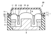
- FIG. 1 is a schematic cross-sectional view showing a configuration of a speaker unit according to the present embodiment.
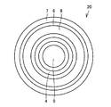
- FIG. 2 is a schematic plan view of the speaker unit shown in FIG. In FIG. 2, the diaphragm and the cover are not shown for easy viewing.
- speaker unit 20 of the present embodiment includes diaphragm member 1, voice coil 4, magnet 5, frame 7, plate 8, yoke 9, and cover 10. It has mainly.
- the diaphragm member 1 has a diaphragm 2 and a ring 3.
- the diaphragm 2 is configured by a thin plate so as to vibrate in the vertical direction (the direction of arrow A in FIG. 1).
- the diaphragm 2 is made of, for example, a synthetic resin.
- the diaphragm 2 includes a circular central portion 21 in plan view, a flat portion 22 formed on the outer peripheral side of the central portion 21, a peripheral portion 23 formed on the outer peripheral side of the flat portion 22, and the peripheral portion 23. And an outer peripheral portion 24 formed on the outer peripheral side.
- the central portion 21 and the peripheral portion 23 are formed in an arc shape in the sectional view of FIG.
- the flat portion 22 is formed flat in the cross-sectional view of FIG.
- An annular ring 3 is attached to the lower surface of the outer peripheral portion 24 of the diaphragm 2.
- the ring 3 constitutes a first convex portion.
- the ring 3 is made of metal, for example.
- the diaphragm 2 is attached to the voice coil 4 by bonding the upper surface of the annular voice coil 4 to the lower surface of the flat portion 22 of the diaphragm 2.
- the magnet 5 is disposed on the outer peripheral side of the voice coil 4 with a gap from the outer peripheral surface of the voice coil 4.
- the yoke 9 has a portion (inner peripheral side portion) disposed on the inner peripheral side of the voice coil 4 with a space from the inner peripheral surface of the voice coil 4, and a portion disposed below the voice coil 4 and the magnet 5. (Lower part).
- the lower part of the yoke 9 is disposed at a distance from the lower surface of the voice coil 4, and the magnet 5 is placed on the lower part of the yoke 9.
- a plate 8 is disposed on the upper surface of the magnet 5.
- There is a known outer magnet type in which a magnetic circuit is constituted by the magnet 5, the plate 8 and the yoke 9.
- the frame 7 supports the magnet 5, the plate 8, and the yoke 9 at the lower part on the inner peripheral side.
- a diaphragm member 1 is attached to the upper part of the frame 7.
- a second convex portion 6 is formed on the upper portion of the frame 7.
- This 2nd convex part 6 is located in the inner peripheral side rather than the ring 3 corresponding to a 1st convex part, for example, as shown in FIG. 2, it is provided so that it may become a circle continuously on the perimeter. ing.
- the inner peripheral surface of the ring 3 faces the outer peripheral surface of the convex portion 6 (second convex portion) provided on the inner peripheral side of the frame 7. Thus, it is attached to the frame 7.
- a circular cover 10 is arranged in plan view so as to cover the diaphragm 2.
- the cover 10 is formed in a trapezoidal shape toward the upper surface.
- the cover 10 is attached to the diaphragm 2 so that the upper surface of the outer peripheral portion 24 of the diaphragm 2 and the lower surface of the outer peripheral portion of the cover 10 face each other.
- the magnetic flux generated from the magnet 5 is guided by the plate 8 and the yoke 9, and converges into the gap where the voice coil 4 is disposed, thereby generating a magnetic field.
- the voice coil 4 vibrates up and down based on Fleming's left-hand rule due to the current flowing through the voice coil 4 and the magnetic field generated from the magnet 5. Therefore, the diaphragm 2 attached to the voice coil 4 vibrates. Thereby, an electric signal (current) is converted into sound (vibration).
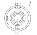
- FIG. 3 is a schematic plan view of the speaker unit when the second convex portion 6 is provided on at least a part of the inner peripheral side of the frame 7.
- the diaphragm 2 and the cover 10 are not shown for ease of viewing as in FIG. 2.
- the 2nd convex part 6 is provided in the four places at equal intervals on the inner peripheral side of the flame
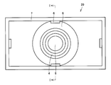
- FIG. 4 is a schematic plan view of the speaker unit when the second convex portion 6 and the frame 7 are provided in a rectangular shape in plan view. Note that in FIG. 4, the diaphragm 2 and the cover 10 are not shown in order to make it easy to see as in FIGS. 2 and 3.
- second protrusion 6 and frame 7 are provided in a rectangular shape in plan view.
- the second convex portion 6 is continuously provided on the entire inner circumference side of the frame 7.
- a schematic cross-sectional view taken along the line II in FIG. 4 is the same as FIG.
- the frame 7 may be provided in a rectangular shape in plan view
- the second convex portion 6 may be provided on at least a part of the inner peripheral side of the frame 7.
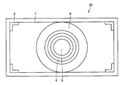
- 5 and 6 are schematic plan views of the speaker unit when the frame 7 is provided in a rectangular shape in plan view and the second convex portion 6 is provided at least at a part on the inner peripheral side of the frame 7. .
- the diaphragm 2 and the cover 10 are not shown for ease of viewing as in FIG. 4.
- frame 7 is provided in a rectangular shape in plan view.
- the second convex portions 6 are respectively provided at the central portions on the long side and the short side on the inner peripheral side of the frame 7.
- a schematic cross-sectional view taken along the line II in FIG. 5 is the same as FIG.
- the frame 7 is provided in a rectangular shape in plan view.
- the second convex portions 6 are provided at the four corners on the inner peripheral side of the frame 7.
- FIG. 7 is a schematic cross-sectional view showing a configuration of a conventional speaker unit.
- this conventional speaker unit 20 the configuration of the upper part of the frame 7 is mainly different from the configuration of the first embodiment. That is, in the shape of the conventional speaker unit 20, the diaphragm 2 is positioned by the inner peripheral surface of the rim portion 71 provided on the outer peripheral side of the frame 7 and the diaphragm outer peripheral surface 72.
- diaphragm edge portion path length 11 (the portion located between the diaphragm edge portion and the voice coil 4 and the length of the arc-shaped portion in the sectional view) is also shortened. More specifically, referring to FIG. 7, diaphragm edge portion path length 11 is defined between the edge portion of diaphragm 2 (outer peripheral portion 24 of diaphragm 2) and flat portion 22 of diaphragm 2 in a sectional view. This is the length of the diaphragm 2. As a result, the sound pressure of the speaker unit 20 decreases due to the area of the diaphragm 2 being reduced. Further, the diaphragm edge portion path length 11 is shortened, whereby the minimum resonance frequency is increased.
- the frame is arranged so that the inner peripheral surface of the ring 3 constituting the first convex portion faces the outer peripheral surface of the second convex portion 6.
- a diaphragm member 1 including a diaphragm 2 and a ring 3 is attached to 7.
- the diaphragm member 1 is positioned on the frame 7.
- the area of the diaphragm member 1 is more increased in the case of the same external dimensions as the conventional speaker unit 20. Can be increased.
- the diaphragm edge portion path length 11 can be increased.
- the area of the diaphragm 2 is smaller than the shape of the conventional speaker unit 20 even if the outer dimensions of the frame 7 are reduced by downsizing and slimming. Can be suppressed.
- a decrease in the diaphragm edge portion path length 11 can be suppressed. Thereby, the fall of the sound pressure of the speaker unit 20 can be suppressed.
- an increase in the minimum resonance frequency can be suppressed.
- the diaphragm member 1 including the diaphragm 2 and the ring 3 can be more stably attached to the frame 7. Can be positioned.
- the diaphragm member 1 including the diaphragm 2 and the ring 3 is stably positioned on the frame 7 by providing the second convex portion 6 on at least a part of the inner peripheral side of the frame 7. be able to.
- the frame 7 may be provided in a rectangular shape, a degree of freedom in design is ensured.
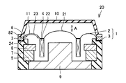
- FIG. 8 is a schematic cross-sectional view of the speaker unit according to the present embodiment.
- the speaker unit according to the present embodiment is mainly different from the first embodiment in that the ring 3 is not provided.
- the diaphragm member 1 has a diaphragm 2.
- the diaphragm 2 has an outer peripheral convex portion 82 on the outer peripheral portion 24.
- the outer peripheral portion 24 is directly attached to the frame upper surface 81.
- the outer periphery convex part 82 comprises the 1st convex part.
- the frame 7 has the second convex portion 6 on the inner peripheral side with respect to the outer peripheral convex portion 82.
- the diaphragm member 1 is positioned on the frame 7.
- the speaker unit 20 according to the present embodiment has the same configuration as the first embodiment because it has the above-described configuration.
- the speaker unit 20 in the present embodiment since the ring 3 is not attached, the man-hour can be reduced as compared with the first embodiment. In addition, the number of parts can be reduced. Thereby, compared with Embodiment 1, a manufacturing cost can be reduced.
- the diaphragm member 1 including the diaphragm 2 can be positioned more stably on the frame 7. it can.
- the second convex portion 6 can be provided on at least a part of the inner peripheral side of the frame 7.
- the 2nd convex part 6 can be provided in four places at equal intervals on the inner peripheral side of the flame
- the diaphragm member 1 including the diaphragm 2 can be positioned on the frame 7 stably.
- the frame 7 can be provided in a rectangular shape in plan view. Thereby, the freedom degree in design is ensured. Even when the frame 7 is rectangular, the second convex portion 6 may be provided continuously on the entire inner circumference side of the frame 7. Thereby, the diaphragm member 1 including the diaphragm 2 can be positioned on the frame 7 more stably.
- the second convex portion 6 can be provided on at least a part of the inner peripheral side of the frame 7.
- the 2nd convex part 6 can each be provided in each center part of the long side of the inner peripheral side of the flame
- the second convex portions 6 can be provided at the four corners on the inner peripheral side of the frame 7. Thereby, the diaphragm member 1 including the diaphragm 2 can be positioned on the frame 7 stably.
- FIG. 9 is a schematic cross-sectional view of the speaker unit according to the present embodiment.
- the speaker unit according to the present embodiment is mainly different from the second embodiment in that the ring 3 is attached to the upper surface of the outer peripheral portion 24 of the diaphragm 2.
- the ring 3 is attached to the upper surface of the outer peripheral portion 24 of the diaphragm 2.
- a cover 10 is attached to the upper surface of the ring 3.
- the ring 3 is attached on the upper surface of the outer peripheral portion 24 of the diaphragm 2 so as to be in contact with the outer peripheral convex portion 82.
- the inner peripheral surface of the outer peripheral convex portion 82 faces the outer peripheral surface of the second convex portion 6 provided on the inner peripheral side of the frame 7 as the inner peripheral surface of the first convex portion, Attached to the frame 7. In this way, the diaphragm member 1 is positioned on the frame 7.
- the speaker unit 20 according to the present embodiment has the same configuration as the first embodiment because it has the above-described configuration.
- the ring 3 is attached to the upper surface of the outer peripheral portion 24 of the diaphragm 2, the ring 3 is held when the diaphragm member 1 is attached to the frame 7. Can be easily attached. That is, handling during assembly is improved.
- the diaphragm member 1 including the diaphragm 2 and the ring 3 can be more stably attached to the frame 7. Can be positioned.
- the second convex portion 6 can be provided on at least a part of the inner peripheral side of the frame 7.
- the 2nd convex part 6 can be provided in four places at equal intervals on the inner peripheral side of the flame
- the diaphragm member 1 can be positioned on the frame 7.
- the frame 7 can be provided in a rectangular shape in plan view. Thereby, the freedom degree in design is ensured. Even if the frame 7 is rectangular, the second convex portion 6 can be provided continuously on the entire inner circumference of the frame 7. Thereby, the diaphragm member 1 including the diaphragm 2 can be positioned on the frame 7 more stably.
- the second convex portion 6 can be provided on at least a part of the inner peripheral side of the frame 7.
- the 2nd convex part 6 can each be provided in each center part of the long side of the inner peripheral side of the flame
- the second convex portions 6 can be provided at the four corners on the inner peripheral side of the frame 7. Thereby, the diaphragm member 1 including the diaphragm 2 can be positioned on the frame 7 stably.
- the outer magnet type speaker unit in which the magnet is disposed on the outer peripheral side from the voice coil has been described.
- the inner magnet type speaker unit in which the magnet is disposed on the inner peripheral side from the voice coil may be used. Good.
- the configuration will be described below. Unless otherwise specified, this configuration is the same as that of the above-described first embodiment, and thus the same elements are denoted by the same reference numerals and description thereof is omitted.
- FIG. 12 is a schematic cross-sectional view showing the configuration of the internal magnet type speaker unit in the present embodiment.
- magnet 5 is disposed on the inner peripheral side of voice coil 4 with a gap from the inner peripheral surface of voice coil 4.
- the yoke 9 includes a portion (outer peripheral portion) disposed on the outer peripheral side of the voice coil 4 with a space from the outer peripheral surface of the voice coil 4 and a portion (lower side portion) disposed below the voice coil 4 and the magnet 5. ).
- the lower part of the yoke 9 is arranged at a distance from the lower surface of the boil coil 4, and the magnet 5 is arranged in the central part of the lower part of the yoke 9.
- the yoke 9 is fitted and fixed to the inner peripheral surface of the frame 7 on the outer peripheral side of the outer peripheral side portion.
- the frame 7 supports the magnet 5 via the yoke 9.
- a plate 8 is disposed on the upper surface of the magnet 5.
- the diaphragm member 1 includes the diaphragm 2 and the ring 3 as in the case of the above-mentioned external magnet type speaker unit.
- An annular ring 3 is attached to the lower surface of the outer peripheral portion 24 of the diaphragm 2.
- the ring 3 constitutes a first convex portion.
- a diaphragm member 1 is attached to the upper part of the frame 7.
- a second convex portion 6 is formed on the upper portion of the frame 7. This 2nd convex part 6 is located in the inner peripheral side rather than the ring 3 corresponding to a 1st convex part.
- the inner peripheral surface of the ring 3 faces the outer peripheral surface of the convex portion 6 (second convex portion) provided on the inner peripheral side of the frame 7.
- a circular cover 10 is arranged in plan view so as to cover the diaphragm 2.
- the operation of the speaker unit with this configuration will be described.
- the magnetic flux generated from the magnet 5 is guided by the plate 8 and the yoke 9 and converges in the gap where the voice coil 4 is disposed, thereby generating a magnetic field.
- the voice coil 4 vibrates up and down based on Fleming's left-hand rule due to the current flowing through the voice coil 4 and the magnetic field generated from the magnet 5. Therefore, the diaphragm 2 attached to the voice coil 4 vibrates.
- the speaker unit having a voice coil having a shape in which the number of layers in the thickness direction is larger than the number of layers in the width direction has been described.
- the speaker unit may be mounted with a voice coil having a shape in which the number of layers in the width direction is larger than the number of layers in the thickness direction. The configuration will be described below.
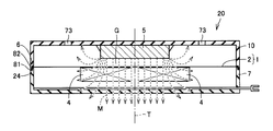
- FIG. 13 is a schematic cross-sectional view showing a configuration of a speaker unit on which a voice coil having a shape in which the number of stacked layers in the width direction is larger than the thickness direction in the present embodiment.
- the diaphragm member 1 has a diaphragm 2.
- the diaphragm 2 has an outer peripheral convex portion 82 constituting a first convex portion on the outer peripheral portion 24.
- the outer peripheral portion 24 is directly attached to the frame upper surface 81.
- the diaphragm 2 has a disk shape.
- the voice coil 4 is attached to the diaphragm 2 by bonding the upper surface of the voice coil 4 to the center of the lower surface of the diaphragm 2.
- the voice coil 4 has a cylindrical shape.
- the magnet 5 is fixed to the center portion of the cover 10 and is arranged at a distance from the upper surface of the diaphragm 2.
- the cover 10 has a cylindrical shape with one end opened.
- a plurality of small holes 73 for sound emission are provided in the cover 10 in a circumferential shape.
- the frame 7 has a cylindrical shape in which one end having the same outer diameter as the cover 10 is opened.
- a second convex portion 6 is formed on the inner peripheral side of the frame 7. The frame 7 and the cover 10 are joined to each other at the respective openings.
- the frame 7 supports the magnet 5 via the cover 10.
- the outer peripheral portion 24 of the diaphragm 2 is fixed by being sandwiched between the frame 7 and the cover 10. As the inner peripheral surface of the outer peripheral convex portion 82 faces the outer peripheral surface of the second convex portion 6 provided on the inner peripheral side of the frame 7 as the inner peripheral surface of the first convex portion, Attached to the frame 7.
- Magnetic flux M (broken arrow in FIG. 13) is radiated from the magnet 5.
- the magnetic flux M acts on the voice coil 4 through the gap G. Then, when the current supplied to the voice coil 4 changes, the voice coil 4 vibrates. Therefore, the diaphragm 2 attached to the voice coil 4 vibrates.
- the number of layers in the direction (width direction) intersecting the central axis T is larger than the number of layers of the voice coil 4 in the central axis T direction (thickness direction). Therefore, the voice coil 4 can be thinned, and the speaker unit 20 equipped with the voice coil 4 can be thinned.
- a plurality of magnets may be mounted.
- This configuration is the same as that of the above-described first embodiment, and thus the same elements are denoted by the same reference numerals and description thereof is omitted.
- FIG. 14 is a schematic cross-sectional view showing a configuration of a speaker unit on which a voice coil and a plurality of magnets having a larger number of stacked layers in the width direction than in the thickness direction are mounted in the present embodiment.
- the voice coil 4 is disposed on the upper surface of the magnet 5 with a gap.
- the voice coil 4 is arranged so that the magnetic flux generated by the magnet 5 crosses the voice coil 4.
- the magnet 5 is magnetized in a direction parallel to the central axis T.
- the magnet 5 includes a pair of rectangular parallelepiped outer magnets 51 and a rectangular parallelepiped inner magnet 52.
- the magnet 5 is fixed by fitting the outer peripheral surface of the outer magnet 51 with the inner peripheral surface of the frame 7.
- the yoke 9 is disposed below the magnet 5 and the frame 7.
- a magnet 5 is placed at the center of the upper surface of the yoke 9.
- the yoke 9 is fixed by fitting the upper surface and side surfaces of the periphery of the yoke 9 with the frame 7.
- the frame 7 supports the magnet 5 on the inner peripheral surface and via the yoke 9.
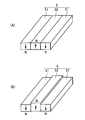
- FIG. 15A is a schematic perspective view of the magnet 5 of FIG.
- the pair of outer magnet 51 and inner magnet 52 are magnetized in the opposite directions. That is, the bottom surfaces of the pair of outer magnets 51 are magnetized so as to be N poles, and the top surfaces of the inner magnets 52 are magnetized so as to be N poles.
- the pair of outer magnets 51 and inner magnets 52 need only be magnetized in opposite directions. Accordingly, the upper surfaces of the pair of outer magnets 51 may be magnetized so as to be N poles, and the lower surfaces of the inner magnets 52 may be magnetized so as to be N poles.
- the diaphragm member 1 includes the diaphragm 2 and the ring 3 as in the case of the above-mentioned external magnet type speaker unit.
- An annular ring 3 is attached to the lower surface of the outer peripheral portion 24 of the diaphragm 2.
- the ring 3 constitutes a first convex portion.
- a diaphragm member 1 is attached to the upper part of the frame 7.
- a second convex portion 6 is formed on the upper portion of the frame 7. This 2nd convex part 6 is located in the inner peripheral side rather than the ring 3 corresponding to a 1st convex part.
- the inner peripheral surface of the ring 3 faces the outer peripheral surface of the convex portion 6 (second convex portion) provided on the inner peripheral side of the frame 7.
- a circular cover 10 is arranged in plan view so as to cover the diaphragm 2.
- the operation of the speaker unit with this configuration will be described.
- the magnetic flux generated from the magnet 5 is converged in the gap where the voice coil 4 is disposed, and a magnetic field is generated.
- the voice coil 4 vibrates up and down based on Fleming's left-hand rule due to the current flowing through the voice coil 4 and the magnetic field generated from the magnet 5. Therefore, the diaphragm 2 attached to the voice coil 4 vibrates.
- the outer magnet 51 and the inner magnet 52 are magnetized in opposite directions. Therefore, the magnetic flux formed by the upper surface of the outer magnet 51 and the upper surface of the inner magnet 52 overlaps with the magnetic flux formed by the lower surface of the outer magnet 51 and the lower surface of the inner magnet 52. Therefore, a high-density magnetic flux passes through the voice coil 4. Thereby, the driving force acting on the diaphragm is increased, and the sound pressure can be increased.
- the inner magnet 52 may have a structure in which the surface of the inner magnet 52 protrudes toward the voice coil 4 than the surface of the outer magnet 51.
- a magnetic flux is formed at a position closer to the voice coil 4. Therefore, a higher density magnetic flux passes through the voice coil 4. As a result, the driving force acting on the diaphragm is increased, and the sound pressure can be further increased.
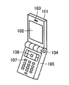
- the portable information terminal in the present embodiment is a mobile phone, and includes upper casing 101, display section 102, sound emitting hole 103, hinge section 104, lower casing 105, and operation. It mainly includes a button 106, a numeric button 107, a display unit 111, a sound emission hole 112, and a speaker unit 20 according to any one of the first to third embodiments (not shown).
- a display unit 102 is provided on the surface of the upper housing 101.
- a sound emitting hole 103 is formed on one end side of the surface of the upper housing 101.
- a hinge portion 104 is formed on the other end side of the upper housing 101.
- a hinge portion 104 is formed on one end side of the lower housing 105.
- the upper housing 101 and the lower housing 105 are connected to each other by a hinge portion 104 so as to be opened and closed.
- An operation button 106 is formed on the surface of the lower housing 105 on the hinge portion 104 side.
- a numeric button 107 is formed from the operation button 106 toward the side opposite to the hinge portion 104.
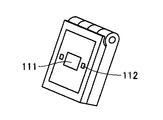
- a display unit 111 is provided on the back surface of the upper casing 101.
- a sound emitting hole 112 is formed beside the display unit 111.
- Any speaker unit 20 described in Embodiments 1 to 3 and FIGS. 12 to 15 (not shown) is provided inside the upper casing 101. A sound is emitted from the speaker unit 20 to the outside of the portable information terminal mainly through the sound emission holes 103 and 112.
- any one of the speaker units 20 described in the first to third embodiments and FIGS. 12 to 15 is provided, Even if the outer dimensions of the frame 7 are reduced, a reduction in the area of the diaphragm 2 can be suppressed as compared with the shape of the conventional speaker unit 20. In addition, a decrease in the diaphragm edge portion path length 11 can be suppressed. Thereby, the fall of the sound pressure of the speaker unit 20 can be suppressed. In addition, an increase in the minimum resonance frequency can be suppressed.
- the portable information terminal in the present embodiment it is possible to make the portable information terminal smaller by further downsizing and slimming.
- the design freedom can be improved by providing the space-saving speaker unit 20.
- by increasing the sound pressure it is possible to clearly recognize a call sound, a ringtone, and the like.
- a mobile phone has been described as a mobile information terminal.
- the present invention is not limited to this and may be a DSC, PDA, PC, or the like.
- the present invention can be applied particularly advantageously to a speaker unit and a portable information terminal that are downsized and slimmed.
- FIG. 3 is a schematic cross-sectional view of the speaker unit according to Embodiment 1.
- FIG. 3 is a schematic plan view of the speaker unit according to Embodiment 1.
- FIG. 3 is a schematic plan view of the speaker unit according to Embodiment 1.
- FIG. 3 is a schematic plan view of the speaker unit according to Embodiment 1.
- FIG. 3 is a schematic plan view of the speaker unit according to Embodiment 1.
- FIG. 3 is a schematic plan view of the speaker unit according to Embodiment 1.
- FIG. It is a schematic sectional drawing of the conventional speaker unit.
- 6 is a schematic cross-sectional view of a speaker unit according to Embodiment 2.
- FIG. 6 is a schematic cross-sectional view of a speaker unit according to Embodiment 3.
- FIG. 10 is a schematic perspective view of a portable information terminal in a fourth embodiment.
- FIG. 10 is a schematic perspective view of a portable information terminal in a fourth embodiment. It is a schematic sectional drawing of the internal magnet type speaker unit in embodiment. It is a schematic sectional drawing of the speaker unit carrying the voice coil of the shape where there are many lamination
- 1 is a schematic cross-sectional view of a speaker unit on which a voice coil and a plurality of magnets having a larger number of laminated layers in the width direction than in the thickness direction in the embodiment are mounted. It is a figure (A) which is a perspective view of the magnet in FIG. 14, and a figure (B) which is a perspective view of the magnet of the structure where the surface of the inner magnet protruded to the voice coil side rather than the surface of the outer magnet.
Landscapes
- Physics & Mathematics (AREA)
- Engineering & Computer Science (AREA)
- Acoustics & Sound (AREA)
- Signal Processing (AREA)
- Audible-Bandwidth Dynamoelectric Transducers Other Than Pickups (AREA)
- Diaphragms For Electromechanical Transducers (AREA)
- Telephone Set Structure (AREA)
Abstract
Description
このように第1および第2の凸部を対向配置させることにより、振動板部材をフレームに対して位置決めして取り付けることが可能となる。
最初に本実施の形態のスピーカユニットの構成について説明する。
なお、図5のI-I線に沿う概略断面図は図1と同様である。
最初に本実施の形態におけるスピーカユニットの構成について説明する。
このようにして、振動板部材1がフレーム7に位置決めされている。
最初に本実施の形態におけるスピーカユニットの構成について説明する。
振動板2は円板状の形状を有している。
マグネット5は、カバー10の中央部に固定され、振動板2の上面と間隔をあけて配置されている。
外周凸部82の内周面が、第1の凸部の内周側の面として、フレーム7の内周側に設けられた第2の凸部6の外周側の面に対向するように、フレーム7に取り付けられている。
図14を参照して、ボイスコイル4は、マグネット5の上面上に間隔をあけて配置されている。ボイスコイル4は、マグネット5によって生じる磁束がボイスコイル4を横切るように配置されている。
つまり、一対のアウターマグネット51の下面がN極となるように磁性化され、インナーマグネット52の上面がN極となるように磁性化されている。なお、一対のアウターマグネット51とインナーマグネット52とは、逆向きに磁性化されていればよい。したがって、一対のアウターマグネット51の上面がN極となるように磁性化され、インナーマグネット52の下面がN極となるように磁性化されていてもよい。
最初に本実施の形態における携帯情報端末の構成について説明する。
Claims (6)
- 外周部に第1の凸部を有する振動板部材と、
前記振動板部材に固定されたボイスコイルと、
前記ボイスコイルと間隔をあけて配置されたマグネットと、
前記マグネットを支持し、かつ前記第1の凸部よりも内周側に第2の凸部を有するフレームとを備え、
前記第1の凸部の内周側の面が前記第2の凸部の外周側の面に対向するように前記フレームに対して前記振動板部材が取り付けられている、スピーカユニット。 - 前記振動板部材は、振動板と、前記振動板の外周部に取り付けられたリングとを含み、 前記リングの内周面が前記第1の凸部の内周側の面として前記第2の凸部の外周側の面に対向する、請求項1に記載のスピーカユニット。
- 前記振動板部材は、振動板を含み、
前記振動板は外周部に外周凸部を有し、前記外周凸部の内周面が前記第1の凸部の内周側の面として前記第2の凸部の外周側の面に対向する、請求項1に記載のスピーカユニット。 - 前記第2の凸部が前記フレームの内周側の全周に連続して設けられている、請求項1~3のいずれかに記載のスピーカユニット。
- 前記第2の凸部が前記フレームの内周側の少なくとも一部に設けられている、請求項1~3のいずれかに記載のスピーカユニット。
- 請求項1~3のいずれかのスピーカユニットを備えた、携帯情報端末。
Priority Applications (3)
| Application Number | Priority Date | Filing Date | Title |
|---|---|---|---|
| CN2009801505532A CN102246539A (zh) | 2008-12-25 | 2009-11-11 | 扬声器单元及便携式信息终端 |
| US13/142,229 US20110317867A1 (en) | 2008-12-25 | 2009-11-11 | Speaker unit and portable information terminal |
| JP2010543976A JPWO2010073839A1 (ja) | 2008-12-25 | 2009-11-11 | スピーカユニットおよび携帯情報端末 |
Applications Claiming Priority (2)
| Application Number | Priority Date | Filing Date | Title |
|---|---|---|---|
| JP2008-330968 | 2008-12-25 | ||
| JP2008330968 | 2008-12-25 |
Publications (1)
| Publication Number | Publication Date |
|---|---|
| WO2010073839A1 true WO2010073839A1 (ja) | 2010-07-01 |
Family
ID=42287462
Family Applications (1)
| Application Number | Title | Priority Date | Filing Date |
|---|---|---|---|
| PCT/JP2009/069205 Ceased WO2010073839A1 (ja) | 2008-12-25 | 2009-11-11 | スピーカユニットおよび携帯情報端末 |
Country Status (4)
| Country | Link |
|---|---|
| US (1) | US20110317867A1 (ja) |
| JP (1) | JPWO2010073839A1 (ja) |
| CN (1) | CN102246539A (ja) |
| WO (1) | WO2010073839A1 (ja) |
Cited By (1)
| Publication number | Priority date | Publication date | Assignee | Title |
|---|---|---|---|---|
| CN112929801A (zh) * | 2021-03-04 | 2021-06-08 | 歌尔股份有限公司 | 扬声器和电子设备 |
Families Citing this family (1)
| Publication number | Priority date | Publication date | Assignee | Title |
|---|---|---|---|---|
| CN103747374A (zh) * | 2013-12-27 | 2014-04-23 | 苏州恒听电子有限公司 | 一种具有改良式壳体的受话器 |
Citations (3)
| Publication number | Priority date | Publication date | Assignee | Title |
|---|---|---|---|---|
| JP2002247689A (ja) * | 2001-02-16 | 2002-08-30 | Citizen Electronics Co Ltd | スピーカ |
| JP2007243870A (ja) * | 2006-03-13 | 2007-09-20 | Matsushita Electric Ind Co Ltd | スピーカ |
| JP2008252237A (ja) * | 2007-03-29 | 2008-10-16 | Casio Hitachi Mobile Communications Co Ltd | 防水音響装置 |
Family Cites Families (17)
| Publication number | Priority date | Publication date | Assignee | Title |
|---|---|---|---|---|
| JPS5527721A (en) * | 1978-08-18 | 1980-02-28 | Sony Corp | Diaphragm for electroacoustic converter |
| JPH01162990U (ja) * | 1988-04-30 | 1989-11-14 | ||
| US5687247A (en) * | 1995-07-13 | 1997-11-11 | Proni; Lucio | Surround for a loudspeaker |
| JP3192100B2 (ja) * | 1996-11-08 | 2001-07-23 | 株式会社オーディオテクニカ | マイクロホン |
| DE60003440T2 (de) * | 1999-09-14 | 2004-04-29 | Nanonord A/S | Membranwandler |
| US7548631B2 (en) * | 2000-01-19 | 2009-06-16 | Harman International Industries, Incorporated | Speaker surround structure for maximizing cone diameter |
| US6714655B2 (en) * | 2001-05-11 | 2004-03-30 | Matsushita Electric Industrial Co., Ltd. | Speaker |
| US6568503B2 (en) * | 2001-09-13 | 2003-05-27 | Jl Audio, Inc. | Loudspeaker with improved mounting structure for the surround |
| JP3896970B2 (ja) * | 2003-01-31 | 2007-03-22 | 松下電器産業株式会社 | スピーカ |
| US7412065B2 (en) * | 2003-04-09 | 2008-08-12 | Harman International Industries, Incorporated | Acoustic transducer with folded diaphragm |
| JP2005277874A (ja) * | 2004-03-25 | 2005-10-06 | Pioneer Electronic Corp | 同軸スピーカー装置及びその製造方法 |
| JP4434830B2 (ja) * | 2004-05-18 | 2010-03-17 | パイオニア株式会社 | ドーム型振動板 |
| JP2006050410A (ja) * | 2004-08-06 | 2006-02-16 | Star Micronics Co Ltd | 電気音響変換装置およびその製造方法 |
| EP1643799B1 (en) * | 2004-09-29 | 2016-05-11 | Alpine Electronics, Inc. | Speaker and manufacturing method of the same |
| US7912239B2 (en) * | 2005-06-06 | 2011-03-22 | The Furukawa Electric Co., Ltd. | Flat speaker |
| KR100714023B1 (ko) * | 2006-03-21 | 2007-05-04 | 엘지전자 주식회사 | 모바일 기기의 스피커 시스템 |
| JP4867442B2 (ja) * | 2006-04-10 | 2012-02-01 | パナソニック株式会社 | スピーカ振動板とそれを用いたスピーカ |
-
2009
- 2009-11-11 JP JP2010543976A patent/JPWO2010073839A1/ja active Pending
- 2009-11-11 CN CN2009801505532A patent/CN102246539A/zh active Pending
- 2009-11-11 WO PCT/JP2009/069205 patent/WO2010073839A1/ja not_active Ceased
- 2009-11-11 US US13/142,229 patent/US20110317867A1/en not_active Abandoned
Patent Citations (3)
| Publication number | Priority date | Publication date | Assignee | Title |
|---|---|---|---|---|
| JP2002247689A (ja) * | 2001-02-16 | 2002-08-30 | Citizen Electronics Co Ltd | スピーカ |
| JP2007243870A (ja) * | 2006-03-13 | 2007-09-20 | Matsushita Electric Ind Co Ltd | スピーカ |
| JP2008252237A (ja) * | 2007-03-29 | 2008-10-16 | Casio Hitachi Mobile Communications Co Ltd | 防水音響装置 |
Cited By (1)
| Publication number | Priority date | Publication date | Assignee | Title |
|---|---|---|---|---|
| CN112929801A (zh) * | 2021-03-04 | 2021-06-08 | 歌尔股份有限公司 | 扬声器和电子设备 |
Also Published As
| Publication number | Publication date |
|---|---|
| US20110317867A1 (en) | 2011-12-29 |
| JPWO2010073839A1 (ja) | 2012-06-14 |
| CN102246539A (zh) | 2011-11-16 |
Similar Documents
| Publication | Publication Date | Title |
|---|---|---|
| JP4215624B2 (ja) | 音響装置 | |
| US8774448B2 (en) | Speaker with elastic plate coupled to diaphragm | |
| JP5518519B2 (ja) | スピーカユニット | |
| JP5615279B2 (ja) | 振動装置および携帯情報端末 | |
| JP5494494B2 (ja) | スピーカユニットおよび携帯情報端末 | |
| US20140056464A1 (en) | Micro-Speaker | |
| US20140056447A1 (en) | Speaker | |
| JP4867031B2 (ja) | 多機能型振動アクチュエータ | |
| US9338534B2 (en) | Miniature speaker | |
| US20130287245A1 (en) | Loudspeaker with reinforced frame | |
| US20100296690A1 (en) | Electro-acoustic transducer | |
| US20210006905A1 (en) | Sounding device | |
| US20130287244A1 (en) | Loudspeaker with reinforced frame | |
| CN101785323A (zh) | 扬声器和使用该扬声器的电子设备 | |
| WO2005091673A1 (ja) | 多機能型振動アクチュエータ及び携帯端末機器 | |
| JPWO2010073839A1 (ja) | スピーカユニットおよび携帯情報端末 | |
| US10631092B2 (en) | Speaker | |
| US10674274B2 (en) | Speaker | |
| JP2006041783A (ja) | 薄型スピーカ | |
| US10764685B2 (en) | Speaker | |
| JP5533667B2 (ja) | スピーカユニットおよび携帯情報端末 | |
| US10820105B2 (en) | Speaker | |
| US12413881B2 (en) | Front cover structure and sounder | |
| JP5643981B2 (ja) | スピーカ、マイク及び電子機器 | |
| JP2008141274A (ja) | 電気音響変換器 |
Legal Events
| Date | Code | Title | Description |
|---|---|---|---|
| WWE | Wipo information: entry into national phase |
Ref document number: 200980150553.2 Country of ref document: CN |
|
| 121 | Ep: the epo has been informed by wipo that ep was designated in this application |
Ref document number: 09834643 Country of ref document: EP Kind code of ref document: A1 |
|
| ENP | Entry into the national phase |
Ref document number: 2010543976 Country of ref document: JP Kind code of ref document: A |
|
| WWE | Wipo information: entry into national phase |
Ref document number: 13142229 Country of ref document: US |
|
| NENP | Non-entry into the national phase |
Ref country code: DE |
|
| 122 | Ep: pct application non-entry in european phase |
Ref document number: 09834643 Country of ref document: EP Kind code of ref document: A1 |