WO2010073698A1 - 改質器付エンジンシステム - Google Patents
改質器付エンジンシステム Download PDFInfo
- Publication number
- WO2010073698A1 WO2010073698A1 PCT/JP2009/007245 JP2009007245W WO2010073698A1 WO 2010073698 A1 WO2010073698 A1 WO 2010073698A1 JP 2009007245 W JP2009007245 W JP 2009007245W WO 2010073698 A1 WO2010073698 A1 WO 2010073698A1
- Authority
- WO
- WIPO (PCT)
- Prior art keywords
- engine
- reformer
- exhaust
- valve
- hydrogen
- Prior art date
- Legal status (The legal status is an assumption and is not a legal conclusion. Google has not performed a legal analysis and makes no representation as to the accuracy of the status listed.)
- Ceased
Links
Images


Classifications
-
- F—MECHANICAL ENGINEERING; LIGHTING; HEATING; WEAPONS; BLASTING
- F02—COMBUSTION ENGINES; HOT-GAS OR COMBUSTION-PRODUCT ENGINE PLANTS
- F02D—CONTROLLING COMBUSTION ENGINES
- F02D9/00—Controlling engines by throttling air or fuel-and-air induction conduits or exhaust conduits
- F02D9/04—Controlling engines by throttling air or fuel-and-air induction conduits or exhaust conduits concerning exhaust conduits
-
- C—CHEMISTRY; METALLURGY
- C01—INORGANIC CHEMISTRY
- C01B—NON-METALLIC ELEMENTS; COMPOUNDS THEREOF; METALLOIDS OR COMPOUNDS THEREOF NOT COVERED BY SUBCLASS C01C
- C01B3/00—Hydrogen; Gaseous mixtures containing hydrogen; Separation of hydrogen from mixtures containing it; Purification of hydrogen; Reversible storage of hydrogen
- C01B3/02—Production of hydrogen; Production of gaseous mixtures containing hydrogen
- C01B3/32—Production of hydrogen; Production of gaseous mixtures containing hydrogen by reaction of gaseous or liquid organic compounds with gasifying agents, e.g. water, carbon dioxide or air
-
- F—MECHANICAL ENGINEERING; LIGHTING; HEATING; WEAPONS; BLASTING
- F02—COMBUSTION ENGINES; HOT-GAS OR COMBUSTION-PRODUCT ENGINE PLANTS
- F02D—CONTROLLING COMBUSTION ENGINES
- F02D13/00—Controlling the engine output power by varying inlet or exhaust valve operating characteristics, e.g. timing
- F02D13/02—Controlling the engine output power by varying inlet or exhaust valve operating characteristics, e.g. timing during engine operation
- F02D13/0223—Variable control of the intake valves only
- F02D13/0234—Variable control of the intake valves only changing the valve timing only
-
- F—MECHANICAL ENGINEERING; LIGHTING; HEATING; WEAPONS; BLASTING
- F02—COMBUSTION ENGINES; HOT-GAS OR COMBUSTION-PRODUCT ENGINE PLANTS
- F02M—SUPPLYING COMBUSTION ENGINES IN GENERAL WITH COMBUSTIBLE MIXTURES OR CONSTITUENTS THEREOF
- F02M25/00—Engine-pertinent apparatus for adding non-fuel substances or small quantities of secondary fuel to combustion-air, main fuel or fuel-air mixture
- F02M25/10—Engine-pertinent apparatus for adding non-fuel substances or small quantities of secondary fuel to combustion-air, main fuel or fuel-air mixture adding acetylene, non-waterborne hydrogen, non-airborne oxygen, or ozone
- F02M25/12—Engine-pertinent apparatus for adding non-fuel substances or small quantities of secondary fuel to combustion-air, main fuel or fuel-air mixture adding acetylene, non-waterborne hydrogen, non-airborne oxygen, or ozone the apparatus having means for generating such gases
-
- F—MECHANICAL ENGINEERING; LIGHTING; HEATING; WEAPONS; BLASTING
- F02—COMBUSTION ENGINES; HOT-GAS OR COMBUSTION-PRODUCT ENGINE PLANTS
- F02M—SUPPLYING COMBUSTION ENGINES IN GENERAL WITH COMBUSTIBLE MIXTURES OR CONSTITUENTS THEREOF
- F02M27/00—Apparatus for treating combustion-air, fuel, or fuel-air mixture, by catalysts, electric means, magnetism, rays, sound waves, or the like
- F02M27/02—Apparatus for treating combustion-air, fuel, or fuel-air mixture, by catalysts, electric means, magnetism, rays, sound waves, or the like by catalysts
-
- F—MECHANICAL ENGINEERING; LIGHTING; HEATING; WEAPONS; BLASTING
- F01—MACHINES OR ENGINES IN GENERAL; ENGINE PLANTS IN GENERAL; STEAM ENGINES
- F01N—GAS-FLOW SILENCERS OR EXHAUST APPARATUS FOR MACHINES OR ENGINES IN GENERAL; GAS-FLOW SILENCERS OR EXHAUST APPARATUS FOR INTERNAL-COMBUSTION ENGINES
- F01N2240/00—Combination or association of two or more different exhaust treating devices, or of at least one such device with an auxiliary device, not covered by indexing codes F01N2230/00 or F01N2250/00, one of the devices being
- F01N2240/30—Combination or association of two or more different exhaust treating devices, or of at least one such device with an auxiliary device, not covered by indexing codes F01N2230/00 or F01N2250/00, one of the devices being a fuel reformer
-
- Y—GENERAL TAGGING OF NEW TECHNOLOGICAL DEVELOPMENTS; GENERAL TAGGING OF CROSS-SECTIONAL TECHNOLOGIES SPANNING OVER SEVERAL SECTIONS OF THE IPC; TECHNICAL SUBJECTS COVERED BY FORMER USPC CROSS-REFERENCE ART COLLECTIONS [XRACs] AND DIGESTS
- Y02—TECHNOLOGIES OR APPLICATIONS FOR MITIGATION OR ADAPTATION AGAINST CLIMATE CHANGE
- Y02T—CLIMATE CHANGE MITIGATION TECHNOLOGIES RELATED TO TRANSPORTATION
- Y02T10/00—Road transport of goods or passengers
- Y02T10/10—Internal combustion engine [ICE] based vehicles
- Y02T10/12—Improving ICE efficiencies
Definitions
- the present invention relates to an engine system equipped with a reformer.
- Patent Document 1 can obtain high reforming efficiency because the temperature of the exhaust gas supplied to the reformer is low under low power operating conditions such as idling or low speed operation. Have difficulty. Therefore, in order to increase the reforming efficiency in a wide operating range, it is necessary to increase the contact area between the exhaust gas and the reformer, and there is a problem that the reformer becomes large.
- An object of the present invention is to provide an engine system capable of improving the amount of exhaust heat recovered from the engine to the reactor and reducing the size of the reformer in the engine system with a reformer.
- the present invention has an adjustment valve that adjusts the exhaust gas flow rate downstream of the reformer mounting portion of the exhaust pipe. Is an engine system with a reformer.
- the reformer by closing the adjustment valve in the middle of the exhaust stroke, a part of the exhaust gas can be confined between the reformer and the engine room, so that the reforming efficiency of the reformer can be increased. Thereby, since a predetermined amount of reformed gas can be generated by the reformer, the reformer can be made smaller.
- the block diagram of this system The structural diagram of a reformer.
- Fig. 1 is a block diagram of this system.
- the reformer 1 is installed in an exhaust pipe 9 near the exhaust valve 7.
- the position of the exhaust pipe 9 where the reformer 1 is provided is installed in the engine head near the exhaust valve 7 or in the exhaust pipe just after being discharged from the engine head.
- an adjustment valve 25 for adjusting the exhaust gas flow rate is installed downstream of the reformer mounting portion of the exhaust pipe 9 where the reformer 1 is installed.
- the pre-reform fuel filled in the pre-reform fuel tank 3 is supplied to the reformer 1 from the pre-reform fuel supply amount adjusting device 11 via the pre-reform fuel pump 4.
- the reformed fuel reformed by the reformer 1 is separated into the hydrogen rich gas and the dehydrogenated fuel by the gas-liquid separator 22, and the dehydrogenated fuel is collected in the dehydrogenated fuel tank 23. Further, the hydrogen rich gas is supplied from the hydrogen rich gas supply amount adjusting device 13 to the intake pipe 8 of the engine.
- the reformer 1 since the reformer 1 is provided in the exhaust pipe positioned near the exhaust valve 7, the reformer 1 is supplied with the combustion gas immediately after being exhausted from the engine cylinder 10 so that the high-temperature engine Exhaust heat is supplied. Further, the exhaust heat supplied to the reformer 1 can be adjusted by controlling the adjusting valve 25 installed on the exhaust downstream side of the reformer 1 to adjust the exhaust gas flow rate.
- the intake pipe 8 of the engine is provided with a dehydrogenation fuel supply amount adjusting device 12 for supplying the dehydrogenated fuel separated by the gas-liquid separation device 22 so that the dehydrogenated fuel can be supplied to the engine cylinder 10. It has become.
- An air flow rate adjusting device 14 for adjusting the air amount is installed in the intake pipe 8 of the engine.
- the operations of the intake valve 6, the exhaust valve 7, the air flow rate adjustment device 14, the pre-reformation fuel supply amount adjustment device 11, the hydrogen rich gas supply amount adjustment device 13, the adjustment valve 25, the pumps 4, 24, etc. It is controlled by an electronic control device (not shown).
- fuels before reforming include hydrocarbon fuels such as gasoline, light oil, kerosene, heavy oil, decalin, cyclohexane, methylcyclohexane, naphthalene, benzene, toluene, ammonia, hydrogen peroxide, nitrogen, oxygen, etc.
- hydrocarbon fuels such as gasoline, light oil, kerosene, heavy oil, decalin, cyclohexane, methylcyclohexane, naphthalene, benzene, toluene, ammonia, hydrogen peroxide, nitrogen, oxygen, etc.
- Those capable of chemically releasing hydrogen by a reforming reaction using a catalyst can be used.
- the fuel after reforming is hydrogen and toluene
- the hydrogen separated by the gas-liquid separation device 22 is supplied from the hydrogen rich gas supply amount adjusting device 13 to the intake pipe 8 of the engine. Then, toluene as dehydrogenated fuel is collected in the dehydrogenated fuel
- the reformer 1 is configured such that a catalyst layer 15 made of a Pt / alumina catalyst is formed on a high thermal conductive substrate 17 provided with flow path protrusions 18.
- a structure in which a hydrogen separation membrane 19 that selectively permeates only hydrogen is laminated on the catalyst layer 15 and a hydrogen flow path 21 is laminated via a spacer 20 is a basic structure and is installed in an engine exhaust pipe.
- the medium supplied to the reformer 1 passes through the fuel flow path 16 and proceeds with the dehydrogenation reaction in contact with the catalyst layer 15 formed on the surface of the high thermal conductive substrate 17 to generate a hydrogen rich gas.
- the generated hydrogen rich gas passes through the hydrogen separation membrane 19 and is discharged from the reformer 1 through the hydrogen flow path 21 via the spacer 20. Further, the hydrogen rich gas and the dehydrogenated fuel that have not passed through the hydrogen separation membrane 19 are discharged out of the reformer 1 through the fuel flow path 16.
- the hydrogen-rich gas and dehydrogenated fuel discharged here merge with the hydrogen-rich gas discharged from the hydrogen flow path 21, mixed, and supplied to the gas-liquid separator 22 in FIG.
- the hydrogen rich gas discharged from the hydrogen flow path 21 may be supplied to the hydrogen rich gas supply amount adjusting device 13 without being mixed with the fuel discharged from the fuel flow path 16. Further, when the hydrogen-rich gas and the dehydrogenated fuel can be sufficiently separated by the hydrogen separation membrane 19 of the reformer 1, the gas-liquid separation device 22 described in FIG. 1 can be omitted. In FIG. 2, the hydrogen separation membrane 19 is provided in order to efficiently perform the dehydrogenation reaction from the medium at a low temperature, but the reformer 1 may be configured without the hydrogen separation membrane 19. Is possible. Further, the basic structure shown in FIG.
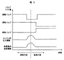
- Fig. 3 shows a time chart for control of this system.
- the abscissa indicates the engine cycle process
- the ordinate indicates the valve lift amounts of the adjusting valve 25, the exhaust valve 7, and the intake valve 6, the pressure history in the engine, and the temperature history of the reformer.
- the adjustment valve 25 is closed during the exhaust stroke of the engine.
- the exhaust valve 7 since the exhaust valve 7 is open, exhaust gas remains between the engine cylinder 10 and the adjustment valve 25 by closing the adjustment valve 25, and the temperature and pressure of the residual exhaust gas are reduced by piston compression. improves. As a result, the amount of heat supplied to the reformer 1 is improved.
- the intake valve 6 In the next intake stroke, the intake valve 6 is closed halfway through the intake stroke, the piston is lowered, and the gas in the engine cylinder 10 expands to reduce the pressure in the engine cylinder 10 to near normal pressure. Open the intake valve 6.
- the loss work of the compression energy in the engine cylinder 10 after closing the adjustment valve 25 at the exhaust stroke is used as the work at the time of piston expansion of the next intake stroke. can do. Thereby, pumping loss can be reduced.
- the residual gas (exhaust gas) in the exhaust process is supplied over the next cycle (intake process).
- the adjustment valve 25 is closed after the exhaust valve 7 of the engine is closed.
- hydrogen which is a part of the fuel reformed by the reformer 1, is supplied to the engine, so that misfire and engine efficiency decrease with respect to the exhaust residual gas compared to when only gasoline is supplied to the engine. It is suppressed. This is because hydrogen has a characteristic that it can be burnt lean and rapidly compared to gasoline.
- the present system can reduce the size of the reformer 1 with the exhaust residual gas without reducing the system efficiency.
- the adjustment valve 25 can be opened and closed via a rotating shaft connected to the crankshaft of the engine.
- the amount of exhaust gas that passes through the reformer varies depending on the timing of closing the regulating valve. Since the steam in the exhaust gas is used for reforming, the amount of reformed gas generated varies depending on the amount of exhaust gas, and the amount of reformed gas supplied to the engine varies. By changing the supply amount of the reformed gas, the amount of hydrogen which is the main component of the reformed gas changes. At this time, it is preferable to delay the ignition timing as the hydrogen content increases so that the optimum ignition timing of the engine is obtained. For this reason, it is preferable to adjust the ignition timing according to the closing timing of the adjusting valve. Specifically, the amount of exhaust gas that passes through the reformer increases as the closing timing of the regulating valve is delayed. This increases the amount of reformed gas generated and increases the amount of hydrogen supplied to the engine. For this reason, it is preferable to perform a control for delaying the ignition timing of the engine as the timing for closing the adjusting valve is delayed.
Landscapes
- Engineering & Computer Science (AREA)
- Chemical & Material Sciences (AREA)
- Combustion & Propulsion (AREA)
- General Engineering & Computer Science (AREA)
- Mechanical Engineering (AREA)
- Organic Chemistry (AREA)
- Chemical Kinetics & Catalysis (AREA)
- Health & Medical Sciences (AREA)
- General Health & Medical Sciences (AREA)
- Inorganic Chemistry (AREA)
- Output Control And Ontrol Of Special Type Engine (AREA)
- Hydrogen, Water And Hydrids (AREA)
- Combined Controls Of Internal Combustion Engines (AREA)
Abstract
Description
Claims (5)
- 排気管に燃料を改質する改質器を搭載した改質器付エンジンシステムにおいて、
前記排気管の改質器搭載部より排気下流側に排気流量を調整する調整バルブを有することを特徴とする改質器付エンジンシステム。 - 請求項1に記載の改質器付エンジンシステムにおいて、前記調整バルブの閉じるタイミングに応じて、エンジンの点火時期を調整することを特徴とする改質器付エンジンシステム。
- 請求項1に記載の改質器付エンジンシステムにおいて、前記調整バルブの開閉制御は、前記エンジンの駆動力を利用することを特徴とする改質器付エンジンシステム。
- 請求項1に記載の改質器付エンジンシステムにおいて、排気行程の途中で前記調整バルブを閉め、前記エンジンの排気バルブが閉まった後に前記調整バルブを開けることを特徴とする前記改質器付エンジンシステム。
- 請求項4に記載の改質器付エンジンシステムにおいて、前記エンジンの吸気バルブの開弁タイミングは、前記調整バルブの閉弁タイミングに応じて調整することを特徴とする前記改質器付エンジンシステム。
Priority Applications (3)
| Application Number | Priority Date | Filing Date | Title |
|---|---|---|---|
| DE112009004372T DE112009004372T5 (de) | 2008-12-25 | 2009-12-25 | Motosystem mit Reformer |
| US13/141,704 US8839606B2 (en) | 2008-12-25 | 2009-12-25 | Engine system with reformer |
| CN2009801526064A CN102265021B (zh) | 2008-12-25 | 2009-12-25 | 带重整器的发动机系统 |
Applications Claiming Priority (2)
| Application Number | Priority Date | Filing Date | Title |
|---|---|---|---|
| JP2008-329000 | 2008-12-25 | ||
| JP2008329000A JP5178498B2 (ja) | 2008-12-25 | 2008-12-25 | 改質器付エンジンシステム |
Publications (1)
| Publication Number | Publication Date |
|---|---|
| WO2010073698A1 true WO2010073698A1 (ja) | 2010-07-01 |
Family
ID=42287331
Family Applications (1)
| Application Number | Title | Priority Date | Filing Date |
|---|---|---|---|
| PCT/JP2009/007245 Ceased WO2010073698A1 (ja) | 2008-12-25 | 2009-12-25 | 改質器付エンジンシステム |
Country Status (5)
| Country | Link |
|---|---|
| US (1) | US8839606B2 (ja) |
| JP (1) | JP5178498B2 (ja) |
| CN (1) | CN102265021B (ja) |
| DE (1) | DE112009004372T5 (ja) |
| WO (1) | WO2010073698A1 (ja) |
Families Citing this family (6)
| Publication number | Priority date | Publication date | Assignee | Title |
|---|---|---|---|---|
| JP5500432B2 (ja) * | 2010-02-10 | 2014-05-21 | 株式会社リコー | 給紙装置及び画像形成装置 |
| US10759724B2 (en) | 2014-09-11 | 2020-09-01 | King Abdullah University Of Science And Technology | Zeolite-like metal-organic frameworks with ana topology |
| EP3191220B1 (en) * | 2014-09-11 | 2021-05-26 | King Abdullah University Of Science And Technology | Method for optimizing fuel for an internal combustion engine |
| WO2017064648A1 (en) | 2015-10-13 | 2017-04-20 | King Abdullah University Of Science And Technology | Zeolite-like metal-organic frameworks with ana topology |
| CN106894922A (zh) * | 2017-04-01 | 2017-06-27 | 哈尔滨工业大学 | 燃料尾气重整化学回热柴油机 |
| CN117231388A (zh) * | 2023-10-20 | 2023-12-15 | 江苏大学 | 一种车载氨气催化裂解制氢装置、控制方法及车辆系统 |
Citations (2)
| Publication number | Priority date | Publication date | Assignee | Title |
|---|---|---|---|---|
| JPS63130663U (ja) * | 1987-02-19 | 1988-08-26 | ||
| JP2006144702A (ja) * | 2004-11-22 | 2006-06-08 | Toyota Motor Corp | 内燃機関及び内燃機関の運転制御装置 |
Family Cites Families (5)
| Publication number | Priority date | Publication date | Assignee | Title |
|---|---|---|---|---|
| JPS54176017U (ja) * | 1978-05-31 | 1979-12-12 | ||
| JP4130912B2 (ja) * | 2003-12-24 | 2008-08-13 | 愛三工業株式会社 | 内燃機関の排気圧上昇装置 |
| US7377101B2 (en) * | 2004-02-13 | 2008-05-27 | Fleetguard, Inc. | Plasma fuel converter NOx adsorber system for exhaust aftertreatment |
| JP4525564B2 (ja) * | 2005-11-16 | 2010-08-18 | トヨタ自動車株式会社 | 内燃機関 |
| JP2008031966A (ja) * | 2006-07-31 | 2008-02-14 | Jfe R & D Corp | Dmeディーゼルエンジン |
-
2008
- 2008-12-25 JP JP2008329000A patent/JP5178498B2/ja not_active Expired - Fee Related
-
2009
- 2009-12-25 CN CN2009801526064A patent/CN102265021B/zh not_active Expired - Fee Related
- 2009-12-25 DE DE112009004372T patent/DE112009004372T5/de not_active Withdrawn
- 2009-12-25 US US13/141,704 patent/US8839606B2/en not_active Expired - Fee Related
- 2009-12-25 WO PCT/JP2009/007245 patent/WO2010073698A1/ja not_active Ceased
Patent Citations (2)
| Publication number | Priority date | Publication date | Assignee | Title |
|---|---|---|---|---|
| JPS63130663U (ja) * | 1987-02-19 | 1988-08-26 | ||
| JP2006144702A (ja) * | 2004-11-22 | 2006-06-08 | Toyota Motor Corp | 内燃機関及び内燃機関の運転制御装置 |
Also Published As
| Publication number | Publication date |
|---|---|
| US20120110984A1 (en) | 2012-05-10 |
| JP2010151000A (ja) | 2010-07-08 |
| JP5178498B2 (ja) | 2013-04-10 |
| DE112009004372T5 (de) | 2012-06-14 |
| US8839606B2 (en) | 2014-09-23 |
| CN102265021B (zh) | 2013-07-24 |
| CN102265021A (zh) | 2011-11-30 |
Similar Documents
| Publication | Publication Date | Title |
|---|---|---|
| CN101033719B (zh) | 发动机系统 | |
| JP4687666B2 (ja) | エンジンシステム | |
| JP5178498B2 (ja) | 改質器付エンジンシステム | |
| WO2009043316A1 (en) | A flexible fuel engine and a controlling method thereof | |
| WO2011040139A1 (ja) | 改質器付エンジンシステム | |
| WO2009101715A1 (ja) | 内燃機関用水素供給装置および内燃機関の運転方法 | |
| US20140048022A1 (en) | Engine system with reformer | |
| JP2022112891A (ja) | 燃料改質装置 | |
| JP2007113461A (ja) | 燃料の着火性を向上させたガスエンジン | |
| JP2009209903A (ja) | 内燃機関の制御装置 | |
| JP2004190586A (ja) | 圧縮着火型内燃機関 | |
| JP4052847B2 (ja) | 燃料改質装置を備えたガスエンジン | |
| WO2019059014A1 (ja) | 内燃機関 | |
| JP2002276519A (ja) | エンジン及びその運転方法 | |
| JP5035358B2 (ja) | エンジンシステム | |
| JP2008240707A (ja) | 燃料改質器付き内燃機関 | |
| JP6527639B2 (ja) | パワートレインシステム | |
| JP5508146B2 (ja) | エンジンシステム及び水素ステーション | |
| JP6392548B2 (ja) | 改質器 | |
| JP5696215B2 (ja) | エンジンシステム | |
| JP2000274285A (ja) | 予混合圧縮自着火エンジンとその制御方法 | |
| JP5331869B2 (ja) | 改質器付エンジンシステム | |
| GB2388465A (en) | A fuel cell plant | |
| JP2007224803A (ja) | 内燃機関 | |
| JP2008127996A (ja) | 内燃機関の排気リフォーマシステム |
Legal Events
| Date | Code | Title | Description |
|---|---|---|---|
| WWE | Wipo information: entry into national phase |
Ref document number: 200980152606.4 Country of ref document: CN |
|
| 121 | Ep: the epo has been informed by wipo that ep was designated in this application |
Ref document number: 09834504 Country of ref document: EP Kind code of ref document: A1 |
|
| WWE | Wipo information: entry into national phase |
Ref document number: 1120090043720 Country of ref document: DE Ref document number: 112009004372 Country of ref document: DE |
|
| WWE | Wipo information: entry into national phase |
Ref document number: 13141704 Country of ref document: US |
|
| 122 | Ep: pct application non-entry in european phase |
Ref document number: 09834504 Country of ref document: EP Kind code of ref document: A1 |