WO2010073296A1 - Nc工作機械のシミュレーション方法及びその装置 - Google Patents
Nc工作機械のシミュレーション方法及びその装置 Download PDFInfo
- Publication number
- WO2010073296A1 WO2010073296A1 PCT/JP2008/003920 JP2008003920W WO2010073296A1 WO 2010073296 A1 WO2010073296 A1 WO 2010073296A1 JP 2008003920 W JP2008003920 W JP 2008003920W WO 2010073296 A1 WO2010073296 A1 WO 2010073296A1
- Authority
- WO
- WIPO (PCT)
- Prior art keywords
- tool
- cut
- workpiece
- interference check
- spindle
- Prior art date
- Legal status (The legal status is an assumption and is not a legal conclusion. Google has not performed a legal analysis and makes no representation as to the accuracy of the status listed.)
- Ceased
Links
Images







Classifications
-
- G—PHYSICS
- G05—CONTROLLING; REGULATING
- G05B—CONTROL OR REGULATING SYSTEMS IN GENERAL; FUNCTIONAL ELEMENTS OF SUCH SYSTEMS; MONITORING OR TESTING ARRANGEMENTS FOR SUCH SYSTEMS OR ELEMENTS
- G05B19/00—Program-control systems
- G05B19/02—Program-control systems electric
- G05B19/18—Numerical control [NC], i.e. automatically operating machines, in particular machine tools, e.g. in a manufacturing environment, so as to execute positioning, movement or co-ordinated operations by means of program data in numerical form
- G05B19/406—Numerical control [NC], i.e. automatically operating machines, in particular machine tools, e.g. in a manufacturing environment, so as to execute positioning, movement or co-ordinated operations by means of program data in numerical form characterised by monitoring or safety
- G05B19/4069—Simulating machining process on screen
-
- G—PHYSICS
- G05—CONTROLLING; REGULATING
- G05B—CONTROL OR REGULATING SYSTEMS IN GENERAL; FUNCTIONAL ELEMENTS OF SUCH SYSTEMS; MONITORING OR TESTING ARRANGEMENTS FOR SUCH SYSTEMS OR ELEMENTS
- G05B2219/00—Program-control systems
- G05B2219/30—Nc systems
- G05B2219/35—Nc in input of data, input till input file format
- G05B2219/35316—Interference checking between tool, machine, part, chuck, machining range
Definitions
- the present invention relates to a simulation method and apparatus for an NC machine tool controlled by a numerical control (hereinafter referred to as NC) apparatus, and more particularly to an improvement in accuracy of interference check.
- NC numerical control
- NC machine tools have become multi-axis and multi-system, and operation has become difficult. Therefore, NC devices have a function to prevent collision (see Patent Document 1).
- the NC machine tool is originally intended to cut the tool into the desired shape by contacting the work, so in the collision prevention function of the NC machine tool and the simulation of the NC machine tool, the combination of the tool and the work is checked for interference. It is common to be excluded from the target.
- the case described in (1) to (3) below is a case where the workpiece and the tool must not contact. It has been proposed to check the interference between the tool and the workpiece (see Patent Document 2).
- the interference and machining abnormality are checked for the movement of the feed axis of the NC machine tool.
- the conventional apparatus cannot detect an abnormality that damages the tool or the workpiece because the rotation direction of the spindle during machining does not match the rotation direction of the spindle that the tool can actually cut.
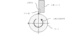
- many turning tools have a blade on only one surface of the cutting tool, and only the surface with the blade can be cut. In the case of such a tool, unless the surface that can be cut of the tool is positioned so as to face the rotation direction of the turning spindle, cutting cannot be performed normally (the rake face of the tool is shown in FIG. 13).
- a turning tool can be mounted on the mill spindle, and the turning tool is rotated around the mill spindle by a predetermined angle, for example, 180 degrees in the case of the opposite spindle.
- a predetermined angle for example, 180 degrees in the case of the opposite spindle.
- the workpiece set up on the second turning spindle side can be machined. The operation of such NC machine tools requires special care.
- the present invention has been made to solve the above-mentioned various conventional problems, and is impossible to cut when the rotation direction of the main spindle of the machine at the time of machining and the main spindle rotation direction at which the tool can actually be cut do not match.
- an NC machine tool simulation method and apparatus capable of performing an interference check between a workpiece and a tool are provided.
- the NC machine tool simulation method of the present invention is a NC machine tool simulation method for simulating the state of machining of a workpiece and the movement of the machine using the shape of the tool or workpiece.
- Predetermining possible spindle rotation direction and cuttable feed axis direction, or spindle rotation direction and non-cuttable feed axis direction for each tool, and the cutting of the selected tool during simulation execution Compares the possible spindle rotation direction or non-cuttable spindle rotation direction with the machine tool's momentary spindle rotation direction to determine whether or not to check the interference between the tool and the workpiece, and is selected during simulation
- the direction of the cutting tool that can be cut or the direction of the feed axis that cannot be cut, and the feed of the machine tool Compare the direction and determine whether the interference check between the tool and the workpiece is necessary based on the comparison result.
- the interference check between the tool and the workpiece is performed.
- a tool and workpiece interference check is performed, and if there is an interference, it is regarded as abnormal.
- the cutting direction of the main spindle that can be cut and the feed axis direction that can be cut, or the main axis rotation direction that cannot be cut and the feed axis direction that cannot be cut are preset in the tool data. It is characterized in that it is determined from the tool's own data.
- the cuttable spindle rotation direction or the uncuttable spindle rotation direction is attached to the tool shape data respectively associated with the data for each tool stored in the tool data. It is expressed by a spindle rotation direction vector that can be cut or a spindle rotation direction vector that cannot be cut.
- the NC machine tool simulation method also provides a tool in which the cutting direction of the main spindle that can be cut and the feed axis direction that can be cut, or the direction of the main spindle that cannot be cut and the direction of the feed axis that cannot be cut are stored in tool data.
- the NC machine tool simulation method of the present invention uses the tool shape data that includes the cutting direction of the spindle that can be cut and the feedable axis direction that can be cut, or the direction of the spindle that cannot be cut and the direction of the feed axis that cannot be cut.
- the tool is given an allowable angle.
- the NC machine tool simulation apparatus is a NC machine tool simulation apparatus that simulates a state in which a workpiece is machined using the shape of the tool or the workpiece or the movement of the machine.
- a storage unit that stores a spindle rotation direction that cannot be cut, a spindle rotation direction of the selected tool that can be cut or a spindle rotation direction that cannot be cut during execution of a simulation, and a spindle rotation direction of a machine tool every moment.
- the interference check condition determination / update unit determines whether or not the interference check between the tool and the workpiece is necessary based on the comparison result and the interference check condition determination / update unit determines that the interference check is unnecessary, If the interference check between the tool and workpiece is not performed and it is determined that the interference check is necessary, the interference check between the tool and workpiece is performed Te, a machine tool simulation unit regarded as abnormal if any interference is made comprises a.
- the NC machine tool simulation apparatus of the present invention is a NC machine tool simulation apparatus that simulates a state in which a workpiece is machined using the shape of the tool or the workpiece or the movement of the machine.
- Storage section for storing the direction and the cuttable feed axis direction, or the unrotatable spindle rotation direction and the uncuttable feed axis direction, and the cuttable spindle rotation direction or cutting of the selected tool during simulation execution
- the impossible spindle rotation direction is compared with the machine tool's momentary spindle rotation direction, and the cutting or non-cuttable feed axis direction of the selected tool and the machine tool's momentary feed axis are compared.
- Interference check condition determination that compares the direction and determines the necessity of the interference check between the tool and the workpiece based on these comparison results. If the new unit and the interference check condition determination / update unit determine that the interference check is not required, do not perform the interference check between the tool and the workpiece. If it determines that the interference check is necessary, perform the interference check between the tool and the workpiece. And a machine tool simulation unit that considers an abnormality if there is interference.
- the NC machine tool simulation apparatus of the present invention is a NC machine tool simulation apparatus for simulating how a workpiece is machined using the shape of the tool or workpiece and the movement of the machine.
- the storage unit for storing, the spindle rotation direction that can be cut or the spindle rotation direction that cannot be cut, and the feed axis direction that can be cut or the feed axis direction that cannot be cut are determined based on the data of the tool.
- the NC machine tool simulation device of the present invention attaches the cuttable spindle rotation direction or the uncuttable spindle rotation direction to tool shape data respectively associated with data for each tool stored in the tool data. It is expressed by a spindle rotation direction vector that can be cut or a spindle rotation direction vector that cannot be cut.
- the NC machine tool simulation apparatus of the present invention is a tool in which the cutting direction of the main spindle that can be cut and the feed axis direction that can be cut, or the direction of the main spindle that cannot be cut and the direction of the feed axis that cannot be cut are stored in tool data.
- the NC machine tool simulation apparatus uses, as tool shape data, the cutting direction of the spindle that can be cut and the feed axis direction that can be cut, or the rotation direction of the spindle that cannot be cut and the feed axis direction that cannot be cut.
- the tool is given an allowable angle.
- the interference check between the workpiece and the tool is performed. Therefore, there are fewer paths that exclude the interference check between the workpiece and the tool, and there is an effect that more abnormal states can be detected.
- the cutting data spindle rotation direction and the cutting feed axis direction, or the non-cutting spindle rotation direction and the non-cutting feed axis direction held in the tool data of the turning tool are preset in the tool data. Since the determination is made from the data of the selected tool, there is an effect that the trouble of setting the tool data for the interference check can be saved.
- the tool data previously set in the tool data includes the cutable feed axis direction and the cuttable spindle rotation direction, or the uncuttable feed axis direction and the uncuttable spindle rotation possessed by the tool data.
- the final orientation of the vector when it is finally assembled is the direction of the feed axis of the virtual NC machine tool and the direction of rotation of the spindle. Since the determination and update of the interference check condition are performed in comparison with the vector, there is an effect that the necessity of the correct interference check can always be determined.
- the tool data has a vector in which the cutting direction of the spindle that can be cut and the feedable axis direction that can be cut, or the direction of the spindle that cannot be cut and the direction of the cutting axis that cannot be cut are attached to the tool shape data.
- the allowable angle is given, and the judgment and update of the interference check condition are carried out with the allowable angle. There is an effect that the determination and update of the interference check condition are more practical.
- FIG. Embodiment 1 is a block diagram showing an NC machine tool simulation apparatus mounted on a computer such as a personal computer according to Embodiment 1 of the present invention.
- 1 is a movement command and feed speed for performing desired machining.
- NC program in which spindle rotation commands are described, 2 is the setting of tool data, operation of the screen displayed through the display device 8, start / end of simulation, setting of the machine tool simulation unit 6, direct movement command
- An input device 3 for supplying and the like is a tool data storage unit 3 that stores information (tool data) about the tool as shown in FIG. 2 for each tool.
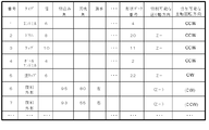
- the tool data includes a tool type and a tool diameter for each tool. , Cutting angle, cutting edge angle, selfishness, shape data number to associate with shape data, cutting axis direction that can be cut (cuttable feed of tool) Direction), and a data such cuttable spindle rotation direction.
- the NC device emulation unit that supplies the current state, such as the current spindle rotation direction, 5 receives various commands and the current various states supplied by the NC device emulation unit 4, and is installed in the current simulation device
- the tool data corresponding to the tool being read is read from the tool data storage unit 3, and the main tool rotation direction that can be cut, the feed axis direction that can be cut, and the NC device emulation unit 4 that the read tool data holds are supplied.
- An interference check condition determination / update unit for determining whether to invalidate, 6 is a workpiece, tool, jig, machine using various commands supplied by the NC device emulation unit 4 and shape data in the shape data storage unit 7
- Machine tool simulation unit that simulates NC machine tool operation and workpiece cutting by moving and changing shape data, etc. 7 stores shape data of workpieces, tools, jigs, machines, etc.
- the shape data storage unit 8 for displaying the coordinate values being executed, the program line being executed, the NC-related data such as the modal, the machine operation being executed by the machine tool simulation unit 6 and the state of the workpiece cutting. It is a display device.
- the NC device emulation unit 4, the interference check condition determination / update unit 5, and the machine tool simulation unit 6 are configured by software.
- the shape data of the workpiece, tool, jig, machine, etc. to be simulated is input from the input device 2 and held in the shape data storage unit 7, and the NC program 1 is also held in the computer. Keep it.
- the tool data storage unit 3 has a restriction on the feed axis direction that can be cut by the tool or the spindle rotation direction that can be cut by the input device 2, the cutting is performed on the tool data.
- the axis name and axis number such as "Z-", “Z +”, and "Z stop” as the possible feed axis directions and their directions, and a fixed rule for the spindle rotation direction that can be cut, for example, in the case of a turning spindle, chuck end face When viewed along the turning spindle from, set clockwise as “CW”, counterclockwise as “CCW”, and set to “stop” when stopped.
- CW When viewed along the tool axis from the tool tip to the tool base side are set. If any of these is not restricted, the place where there is no restriction is left empty.
- the Z direction refers to the same direction as the axial direction of the workpiece rotating in the turning process.
- the turning tool (No. 6, 7 in FIG. 2) has a tool having a shape in which the feed axis direction that can be cut is substantially specified, and this difference in shape is called “selfish”. Are distinguished. Distinguish between the right edge and the left edge of the tool when the tool edge is facing down and the shank is facing up. Called left-handed and distinguished.
- the tool data storage unit 3 is arbitrarily set, but the feed axis direction that can be cut and the spindle rotation direction that can be cut are set in the tool data storage unit 3 In this case, the direction of the feed shaft that can be cut and the direction of rotation of the main shaft that can be cut are determined from the information of this hand.
- the tool data of a certain turning tool does not specify the cutting direction of the feed axis that can be cut and the direction of rotation of the spindle that can be cut
- the right hand is set as the right hand data
- the direction of the cutting axis that can be cut "Z-" as the cutting direction
- "CCW” is set as the cutting direction of the spindle that can be cut.
- "Z-" is set as the cutting axis direction that can be cut
- the cutting direction of the spindle that can be cut To set “CW”.
- the data (Z-, CW, CCW) in parentheses described in the column of the feedable axis direction that can be cut and the column of the spindle rotation direction that can be cut are the feed axis direction and the cutting that can be initially cut.
- the possible spindle rotation direction was not set, it was shown that it was set based on this hand because it was set (because it was set).
- the NC device emulation unit 4 When the simulation is started (ST1), the NC device emulation unit 4 reads the NC program 4 when simulating the automatic operation by the NC program 1, and reads the command when there is a direct command from the input device 2.
- the internal state such as the current tool number, current position, feed speed, spindle rotation speed, spindle rotation direction, control mode, etc. managed by itself is updated (ST3) and the machine tool simulation unit 6 is updated.
- the interference check condition determination / update unit 5 outputs various commands such as a movement command, a tool replacement command, and a spindle rotation command, and the current state such as the currently installed tool number and the current spindle rotation direction (ST4). ). If there is no command in ST2, the simulation is terminated (ST8).
- the interference check condition determining / updating unit 5 can compare and cut the feed axis direction of the currently mounted tool with the feed axis direction of the current movement command, and cut according to the processing flow (see FIG. 4) described later. Whether the spindle rotation direction is compared with the current spindle rotation direction, and whether the interference check between the workpiece and the tool edge is enabled (whether to check the interference between the workpiece and the tool edge) or disabled ( (Set whether to check the interference between the workpiece and the tool edge) is determined (ST5). Of the parts of the tool, parts other than the tool cutting edge are parts where the workpiece cannot be cut in the first place, and are therefore always subject to interference check. Further, for example, the interference check disclosed in Japanese Patent Application Laid-Open No. 2008-27045 can also be set as an interference check target.
- the machine tool simulation unit 6 uses the movement command supplied from the NC device emulation unit 4, the shape data read from the shape data storage unit 7, etc. Interference check determined by the interference check condition judgment / update unit 5 by simulating various behaviors of the machine tool by simulating the exchange behavior or simulating the movement of each part of the machine tool by movement of each axis An interference check is performed according to the conditions (ST6). There are many known techniques for specific methods of interference check, and any of them may be used, and what is determined as “interference”, for example, each part in the machine tool Whether it is considered as interference or near miss when the distance is less than a certain distance is free, the interference check technique (algorithm for detecting interference) and the range considered as interference are the features of this invention. It has no effect.
- the machine tool simulation unit 6 detects interference, for example, the simulation is temporarily stopped, and the display device 8 performs notification processing such as highlighting the interference site or displaying the alarm content as a character string (ST7). ).
- the tool data is read from the tool data storage unit 3, the tool data corresponding to the number of the currently mounted tool supplied from the NC device emulation unit 4 is specified, and feed axis direction data that can be cut into the tool is determined. It is confirmed whether it has (ST5-1). If the result of ST5-1 is yes, it is confirmed whether or not the feedable axis direction of the tool matches the current feed axis direction supplied from the NC device simulator unit 4 (ST5-2). If the result of ST5-1 is no, the process proceeds to ST5-4 described next.
- the tool data is read from the tool data storage unit 3, the tool data corresponding to the number of the currently mounted tool supplied from the NC device emulation unit 4 is specified, and It is confirmed whether or not it has a spindle rotation direction that can be cut (ST5-4). If the result of ST5-2 is no, the interference check between the workpiece and the tool edge is validated (ST5-3), and the process ends. If the result of ST5-4 is yes, it is confirmed whether the spindle rotation direction in which the tool can be cut matches the current spindle rotation direction supplied from the NC device emulation unit 4 (ST5-5). When the result of ST5-4 is no, the interference check between the workpiece and the tool edge is invalidated (ST5-6), and the process ends.
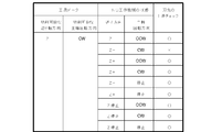
- the validity / invalidity of the interference check between the tool edge and the workpiece is determined according to the state of the NC machine tool. Is set as in the “Checking the interference of the cutting edge” field.
- the case marked with ⁇ is set to check the interference between the tool blade and the workpiece, and the case marked with ⁇ is checked for interference between the tool blade and the workpiece. This is a setting that is not performed.
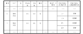
- a plurality of directions can be set as the feed axis direction in which the tool data can be cut, or cutting is possible.
- Multiple spindle rotation directions may be set.
- the tool edge / workpiece interference check is enabled / disabled depending on the state of the NC machine tool. It is set like this.
- a pair of a cuttable feed axis direction and a cuttable spindle rotation direction may be set and a plurality of pairs may be set.
- the tool data storage unit 3 stores the feedable axis direction that can be cut and the rotation direction of the main spindle that can be cut.
- the main spindle rotation direction may be stored.
- the interference check condition determining / updating unit 5 validates the interference check when the feed axis direction that cannot be cut matches the current feed direction, and invalidates the interference check when they do not match. Also, the interference check is validated when the spindle rotation direction that cannot be cut matches the current spindle rotation direction, and the interference check is invalidated when they do not match.
- the feed axis direction that can be cut for each tool (or the feed axis direction that cannot be cut) and the spindle rotation direction that can be cut (or the spindle rotation direction that cannot be cut) are set. It is determined whether or not cutting is possible by comparing with the feed axis direction and the spindle rotation direction of the virtual NC machine tool during simulation execution. Therefore, the number of paths for excluding the workpiece / tool interference check is reduced, and more abnormal states can be detected than in the conventional method.
- the NC machine tool simulation device mounted on the computer has been described as a simulation of NC behavior.
- the simulation device is mounted in the NC device mounted on the NC machine tool.
- the NC device that controls the actual machine tool may be replaced with the NC device emulation unit 4.
- this simulation device is installed in an NC unit that has a function to check for interference during operation of an actual machine and to prevent collision of each part existing in the movable area of the machine tool. May be.
- an interference check condition determination / update unit 5 and a machine tool simulation unit 6 are mounted as a “collision detection unit” of a numerical control system disclosed in Japanese Patent Application Laid-Open No. 2008-129994, and an actual machine tool is controlled.
- the NC device may be replaced with the NC device emulation unit 4.
- Embodiment 2 Although the basic operation of the second embodiment is the same as that of the first embodiment, the interference check condition determination / update process in FIG. 3 showing the operation of the NC machine tool simulation of the first embodiment is shown. ST5 is different, and the feed axis direction that can be cut and the spindle rotation direction that can be cut are attached to the tool shape data stored in the shape data storage unit 7 as a vector, and are thus determined. It is. Hereinafter, only processing different from that of the first embodiment will be described.
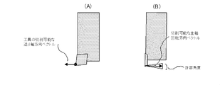
- FIG. 8 shows an example of the shape data of the tool according to the second embodiment.
- FIG. 8A shows the same turning tool as viewed from the rake face, and FIG. FIG. 8 (A) is rotated 90 degrees to the left of the page and viewed from the side.
- the shape data of the tool in the second embodiment has the feedable axis direction shown in FIG. 8 (A) and the cuttable spindle rotation direction shown in FIG. 8 (B) as vectors. . Further, an allowable angle is given to the spindle rotation direction vector that can be cut.
- FIG. 9 shows a processing flow of another form of the interference check condition determination / update processing.
- the tool data is read from the tool data storage unit 3
- the tool data corresponding to the number of the currently mounted tool supplied from the NC device emulation unit 4 is specified, and the shape data is further read from the shape data storage unit 7.
- the tool shape data is read and specified, and it is confirmed whether it has a feed axis direction vector that can be cut (ST5-A).
- the feed axis direction vector that can be cut by the tool and the current feed axis direction supplied from the NC device emulation unit 4 are expressed by a vector, and it is confirmed whether they match. (ST5-B). If the result of ST5-A is no, the process proceeds to ST5-D described next. If the result of ST5-B is yes, the shape data is read from the shape data storage unit 7 and it is confirmed whether or not the tool has a spindle rotation direction vector that can be cut (ST5-D). If the result of ST5-B is no, the interference check between the workpiece and the tool edge is validated (ST5-C) and the process ends.
- the tangent vector in the current spindle rotation direction supplied from the NC device emulation unit 4 at the tool edge point of a circle whose radius is the distance from the spindle rotation center to the tool edge point is It is obtained and used as the current spindle rotation direction vector (ST5-E), and in the next ST5-F, the tool cutting spindle rotation direction vector and the tool cutting spindle rotation direction vector obtained in ST5-E are calculated. It is confirmed whether the formed angle is within the allowable angle with respect to the spindle rotation direction vector of the tool (ST5-F). If the result of ST5-D is no, the interference check between the workpiece and the tool edge is invalidated (ST5-G), and the process ends.
- the tool shown in FIGS. 8A and 8B is mounted at a certain point in the middle of the simulation execution, and the direction of the feed axis where the tool can be cut and the current feed of the NC machine tool.
- the angle formed by the rotation direction vector of the turning spindle of the NC machine tool and the spindle rotation direction vector that can be cut by the tool is within an allowable angle, correct cutting is performed. Therefore, the interference check between the workpiece and the tool edge is invalidated.
- the angle between the rotation direction vector of the turning spindle of the NC machine tool and the rotation direction vector of the spindle that can be cut by the tool is an allowable angle. If it is outside, correct cutting cannot be performed, so the interference check between the workpiece and the tool edge is enabled.
- the shape data storage unit 7 stores the feedable axis direction vector that can be cut and the main spindle rotation direction vector that can be cut.
- a main spindle rotation direction vector may be stored.
- the interference check condition determining / updating unit 5 validates the interference check when the feed axis direction vector that cannot be cut matches the current feed direction vector, and invalidates the interference check when they do not match. Become. Further, the interference check is validated when the spindle rotation direction vector that cannot be cut matches the current spindle rotation direction vector, and the interference check is invalidated when they do not match.
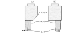
- FIG. 11 shows a turning tool of a type that is mounted on a mill spindle that is often used in a multi-task machine, and includes a holder, a shank, and a tip (blade edge).
- the orientation of the rake face of the final tool is determined by the rotation angle of the mill spindle, the holder's handling ability, and the shank's ability.
- FIG. 11A is a view with the rake face up
- FIG. 11B is a view when FIG. 11A is turned 90 degrees to the left side of the page and viewed from the side.
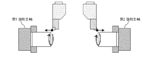
- these three parts are defined by CAD data, a modeling language, etc., and combined in a three-dimensional space to form a single tool. If the main axis rotation direction that can be cut and the feed axis direction that can be cut are set as fixed vectors with respect to the shank shape data, the final cutting direction is determined even if it is assembled in the holder. This eliminates the need for the operator to manually input such information into the tool data. Further, as shown in FIG. 12, when this tool is rotated 180 degrees around the tool axis in order to machine a workpiece on the second turning spindle located facing the first turning spindle, the cutting applied to the shape is performed.
- each tool has a feed axis direction that can be cut and a spindle rotation direction that can be cut as a vector, and during simulation, the feed axis direction and spindle rotation direction of the virtual NC machine tool have an allowable angle.
- the NC machine tool simulation method and apparatus according to the present invention are suitable for checking in advance the interference between the tool edge and the workpiece when machining the workpiece by controlling the machine tool with the NC.
Landscapes
- Engineering & Computer Science (AREA)
- Human Computer Interaction (AREA)
- Manufacturing & Machinery (AREA)
- Physics & Mathematics (AREA)
- General Physics & Mathematics (AREA)
- Automation & Control Theory (AREA)
- Numerical Control (AREA)
Abstract
Description
しかし工具としてドリルなどの回転工具を使用するNC工作機械における実際の使用状況では、次の(1)~(3)に記載の場面の場合は、ワークと工具が接触してはいけない場合であるとして、工具とワークとの干渉チェックを行うことが提案されている(特許文献2参照)。
(1)主軸の回転が停止している場合(回転工具の回転が停止しているとき)、
(2)ワークに対する工具の相対送り速度である切削送り速度がワークの材質に応じた設定最大切削送り速度を超えた場合、
(3)ドリル(またはタップ)を、ドリル(またはタップ)の切削可能軸方向であるZ軸と直行するX軸、Y軸方向に移動させて、このドリル(またはタップ)を穴加工位置へ位置決め移動させる場合。
しかし、従来のものは、加工時の主軸の回転方向と工具が実際に切削可能な主軸回転方向とが不一致であることが原因で、工具やワークを損傷するような異常を検出できない。
例えば、図13に示すように、旋削バイトにはバイトの1面だけに刃があり、刃のある面だけが切削可能となっているものが多い。このような工具の場合には、旋削主軸の回転方向と向き合うように工具の切削可能な面が位置しなければ、正常に切削することができない(工具のすくい面が図13に示すように図の左側方向を向いており、且つ主軸が図13に示すような反時計回りの回転をする場合には、ワークを正常に切削することができない)。特に、旋削機能とミリング機能の両方を有する複合加工機ではミル主軸に旋削工具を装着することができ、しかもこのミル主軸周りに旋削工具を所定の角度、例えば対向主軸の場合には180度回転させて、第2旋削主軸側に段取りされているワークを加工できるように構成されているものがある。このようなNC工作機械の運転は殊更に注意を要する。
従って、送り軸方向が正しいか否かといった判定だけ、あるいは、主軸が回転しているか否か(ONかOFFか)の判断だけでは、工具が切削できない状態においてワークが接触し、工具やワークを損傷してしまうといった異常状態を検知できない場合が生じてしまう。
2 入力デバイス
3 工具データ記憶部
4 NC装置エミュレーション部
5 干渉チェック条件判定・更新部
6 工作機械シミュレーション部
7 形状データ記憶部
8 表示デバイス
以下、この発明の実施の形態1を図1~図7を用いて説明する。
図1は、この発明の実施の形態1に係る、パーソナルコンピュータなどの計算機上に搭載したNC工作機械のシミュレーション装置を示すブロック図であり、1は所望の加工を行うための移動指令や送り速度、主軸回転指令などが記述されているNCプログラム、2は工具データの設定、表示デバイス8を通して表示されている画面の操作、シミュレーションの始動・終了、工作機械シミュレーション部6の設定、直接に移動指令供給等を行うための入力デバイス、3は図2に示すような工具に関する情報(工具データ)を工具毎に記憶した工具データ記憶部であり、この工具データは工具毎に、工具タイプ、工具径、切込み角、刃先角、勝手、形状データと関連付けるための形状データ番号、切削可能な送り軸方向(工具の切削可能な送り軸方向)、切削可能な主軸回転方向等のデータから構成されている。
なお、NC装置エミュレーション部4、干渉チェック条件判定・更新部5、工作機械シミュレーション部6は、ソフトウエアにより構成される。
まずシミュレーションを開始する前に、入力デバイス2より、シミュレーション対象のワーク、工具、治具、機械などの形状データを入力して形状データ記憶部7に保持し、NCプログラム1も計算機内に保持しておく。
また、図2に示すように工具データ記憶部3に、入力デバイス2より、工具に切削可能な送り軸方向や切削可能な主軸回転方向に関する制限がある場合には、工具データに対して、切削可能な送り軸方向として「Z-」「Z+」「Z停止」等の軸名称や軸番号とその方向を設定し、切削可能な主軸回転方向として一定のルール、例えば旋削主軸の場合、チャック端面から旋削主軸に沿って眺めたときに時計回りを「CW」、反時計回りを「CCW」とし、停止しているときは「停止」を設定する。回転工具の場合には、工具先端から工具の根元側に工具軸に沿って眺めたときの「CW」、「CCW」、「停止」を設定するようにする。これらの何れかに制限がない場合には、制限がない箇所を空としておく。
なお、ここでZ方向とは、旋削加工において回転するワークの軸線方向と同方向を指す。
なお、図2において、切削可能な送り軸方向の欄及び切削可能な主軸回転方向の欄に記載の丸括弧内のデータ(Z-,CW、CCW)は、当初 切削可能な送り軸方向と切削可能な主軸回転方向が設定されていなかったが、勝手が設定されていたため(設定されたため)、この勝手に基づいて設定されたことを示している。
指令があるときには(ST2)、自身の管理する現在の工具番号、現在位置、送り速度、主軸回転速度、主軸回転方向、制御モードなどの内部状態を更新する(ST3)と共に、工作機械シミュレーション部6および干渉チェック条件判定・更新部5に、移動指令、工具交換指令、主軸回転指令等の各種指令と、現在装着している工具番号、現在の主軸回転方向等の現在の状態を出力する(ST4)。
ST2にて指令がない場合には、シミュレーションを終了する(ST8)。
干渉チェック条件判定・更新部5は、後述する処理フロー(図4参照)によって、現在装着している工具が有する切削可能な送り軸方向と現在の移動指令の送り軸方向の比較、切削可能な主軸回転方向と現在の主軸回転方向の比較を行い、ワークと工具刃先の干渉チェックを有効に設定するか(ワークと工具刃先の干渉チェックを行うように設定するか)、無効に設定するか(ワークと工具刃先の干渉チェックを行わないように設定するか)を決定する(ST5)。
なお、工具の各部位のうち、工具刃先以外の部位は、そもそもワークを削ることができない部位であるので、常に干渉チェックの対象とする。
また、例えば特開2008-27045号公報に開示の干渉チェックも、干渉チェック対象とすることも可能である。
なお、干渉チェックの具体的な手法に関しては数多の公知技術があり、そのうちの何れを用いてもよく、また、何をもって「干渉」と判断するかについて、例えば、工作機械内の各部位が一定の距離以下となったときに干渉とみなすか、あるいはニアミスとみなすかなどは自由であり、干渉チェックの手法(干渉を検知するアルゴリズム)や干渉とみなす範囲はこの発明の特徴とするところになんら影響を与えない。
工作機械シミュレーション部6で干渉を検知した場合には、例えばシミュレーションを一時停止し、表示デバイス8で、干渉部位を強調表示したり、アラーム内容を文字列で表示したりといった通知処理を行う(ST7)。
まず、工具データ記憶部3から工具データを読込んで、NC装置エミュレーション部4から供給された現在装着している工具の番号に相当する工具データを特定し、工具に切削可能な送り軸方向データを有しているかを確認する(ST5-1)。
ST5-1の結果がyesの場合、工具の切削可能な送り軸方向と、NC装置シミュレータ部4から供給された現在の送り軸方向と一致しているかを確認する(ST5-2)。
ST5-1の結果がnoの場合、次に説明するST5-4に遷移する。
ST5-2の結果がyesの場合、工具データ記憶部3から工具データを読込んで、NC装置エミュレーション部4から供給された現在装着している工具の番号に相当する工具データを特定し、工具に切削可能な主軸回転方向を有しているかを確認する(ST5-4)。
ST5-2の結果がnoの場合、ワークと工具刃先の干渉チェックを有効化し(ST5-3)、終了する。
ST5-4の結果がyesの場合、工具の切削可能な主軸回転方向と、NC装置エミュレーション部4から供給された現在の主軸回転方向が一致しているかを確認する(ST5-5)。
ST5-4の結果がnoの場合、ワークと工具刃先の干渉チェックを無効化し(ST5-6)、終了する。
ST5-5の結果がyesの場合、ST5-6に遷移し、ワークと工具刃先の干渉チェックを無効化し、処理を終了する。
ST5-5の結果がnoの場合、ST5-3に遷移し、ワークと工具刃先の干渉チェックを有効化し、処理を終了する。
ここで、図5の「刃先の干渉チェック」の欄で○が記されているケースは工具刃先とワークの干渉チェックを行う設定、×が記されているケースは工具刃先とワークの干渉チェックを行わない設定である。
また、工具データとして、図7のように、切削可能な送り軸方向と切削可能な主軸回転方向を一対にして、複数の対で設定するようにしても良い。
この場合、干渉チェック条件判定・更新部5は、切削不能な送り軸方向と現在の送り方向とが一致するとき干渉チェックを有効にし、また不一致であるとき干渉チェックを無効にすることになる。また切削不能な主軸回転方向と現在の主軸回転方向とが一致するとき干渉チェックを有効にし、また不一致であるとき干渉チェックを無効にすることになる。
また、実際の機械を運転している最中に干渉をチェックして未然に工作機械の可動領域内に存在する各部位の衝突を防止する機能を備えたNC装置に、本シミュレーション装置を搭載してもよい。例えば特開2008-129994号公報に示されている数値制御システムの「衝突検知部」として干渉チェック条件判定・更新部5と工作機械シミュレーション部6を搭載し、実際の工作機械を制御しているNC装置をNC装置エミュレーション部4と置き換えても良い。これらの構成の違いは、この発明の特徴とするところになんら影響するものではない。
本実施の形態2は、基本的な動作は実施の形態1と同じであるが、実施の形態1のNC工作機械のシミュレーションの動作を示した図3のうちの干渉チェック条件判定・更新の処理ST5が異なり、また切削可能な送り軸方向や切削可能な主軸回転方向を、形状データ記憶部7に保存されている工具の形状データにベクトルとして付しておき、それによって判断するようにしたものである。
以下では、実施の形態1とは異なる処理についてのみ説明する。
図8は本実施の形態2における工具の形状データの例を示すもので、同一の旋削バイトに対して、図8(A)はすくい面を上にして眺めたもの、図8(B)は図8(A)を紙面左側に90度回して横から眺めたものである。
本実施の形態2における工具の形状データには、図8(A)に示す切削可能な送り軸方向と、図8(B)に示す切削可能な主軸回転方向を、各々ベクトルで有している。さらに切削可能な主軸回転方向ベクトルに対して許容角度が付されている。
まず、工具データ記憶部3から工具データを読込んで、NC装置エミュレーション部4から供給された現在装着している工具の番号に相当する工具データを特定し、さらに形状データ記憶部7から形状データを読込んで、工具形状データを特定し、切削可能な送り軸方向ベクトルを有しているかを確認する(ST5-A)。
ST5-Aの結果がyesの場合、工具の切削可能な送り軸方向ベクトルと、NC装置エミュレーション部4から供給された現在の送り軸方向をベクトルで表現し、両者が一致しているかを確認する(ST5-B)。
ST5-Aの結果がnoの場合、次に説明するST5-Dに遷移する。
ST5-Bの結果がyesの場合、形状データ記憶部7から形状データを読込んで、工具の切削可能な主軸回転方向ベクトルを有しているかを確認する(ST5-D)。
ST5-Bの結果がnoの場合、ワークと工具刃先の干渉チェックを有効化し(ST5-C)、終了する。
ST5-Dの結果がnoの場合、ワークと工具刃先の干渉チェックを無効化し(ST5-G)、終了する。
ST5-Fの結果がyesの場合、ST5-Gに遷移し、ワークと工具刃先の干渉チェックを無効化し、処理を終了する。
ST5-Fの結果がnoの場合、ST5-Cに遷移し、ワークと工具刃先の干渉チェックを有効化し、処理を終了する。
この場合、干渉チェック条件判定・更新部5は、切削不能な送り軸方向ベクトルと現在の送り方向ベクトルとが一致するとき干渉チェックを有効にし、また不一致であるとき干渉チェックを無効にすることになる。また切削不能な主軸回転方向ベクトルと現在の主軸回転方向ベクトルとが一致するとき干渉チェックを有効にし、また不一致であるとき干渉チェックを無効にすることになる。
一般的に、1本の工具は複数の部品から構成されている。例えば、図11は複合加工機でよく使用されるミル主軸に装着するタイプの旋削工具を示したもので、ホルダ、シャンク、チップ(刃先)で構成される。このような工具の場合、最終的な工具のすくい面の向きは、ミル主軸の回転角度、ホルダの対応勝手、シャンクの勝手によって定まる。なお、図11(A)は、すくい面を上にして眺めたもの、図11(B)は図11(A)を紙面左側に90度回して横から眺めたものである。
この工具を使ってシミュレーションを行う際には、これらの3つの部品を各々CADデータやモデリング言語などで定義しておき、それらを3次元空間で組み合わせることで1本の工具とする。切削可能な主軸回転方向と切削可能な送り軸方向をシャンクの形状データに対して固定のベクトルで設定しておけば、ホルダに組みこんでも最終的な切削可能な方向が決定されるので、わざわざ工具データにこれらの情報を作業者が手で入力する必要が無くなる。
さらに、図12に示すように、この工具が第1旋削主軸と向かい合って位置する第2旋削主軸にあるワークを加工するために工具軸周りに180度回転した時、形状に付されている切削可能な主軸回転方向のベクトルと切削可能な送り軸方向のベクトルが工具の回転に追従して回転するため、工具の切削可能な主軸回転方向と切削可能な送り軸方向は常に正しい向きを示し、正しい判定が行えるようになる。
さらに、工具毎に切削可能な送り軸方向、切削可能な主軸回転方向をベクトルで有するようにした上でシミュレーション実行中に仮想のNC工作機械の送り軸方向、主軸回転方向を、許容角度を持って比較して切削可能か否かを判定するようにしたことで、より正確に干渉チェック条件の判定ができるようになる。
Claims (12)
- 工具やワークの形状を用いてワークが加工される様子や機械の動きをシミュレーションするNC工作機械のシミュレーション方法において、
シミュレーション実行前に、工具毎に切削可能な主軸回転方向または切削不能な主軸回転方向を予め決定するステップと、
シミュレーション実行中に、選択されている工具の前記切削可能な主軸回転方向または切削不能な主軸回転方向と、工作機械の刻々の主軸回転方向とを比較し、この比較結果に基づいて工具とワークの干渉チェックの要否を判断するステップと、
前記のステップで干渉チェック不要と判断した場合、工具とワークの干渉チェックを行わず、干渉チェック要と判断した場合、工具とワークの干渉チェックを行って、干渉があれば異常とみなすステップと、
を有することを特徴とするNC工作機械のシミュレーション方法。 - 工具やワークの形状を用いてワークが加工される様子や機械の動きをシミュレーションするNC工作機械のシミュレーション方法において、
シミュレーション実行前に、工具毎に切削可能な主軸回転方向及び切削可能な送り軸方向、または工具毎に切削不能な主軸回転方向及び切削不能な送り軸方向を予め決定するステップと、
シミュレーション実行中に、選択されている工具の前記切削可能な主軸回転方向または切削不能な主軸回転方向と、工作機械の刻々の主軸回転方向とを比較し、工具とワークの干渉チェックの要否を判断するステップと、
シミュレーション実行中に、選択されている工具の前記切削可能な送り軸方向または切削不能な送り軸方向と、工作機械の刻々の送り軸方向とを比較し、この比較結果に基づいて工具とワークの干渉チェックの要否を判断するステップと、
前記の各ステップで干渉チェック不要であると判断した場合、工具とワークの干渉チェックを行わず、干渉チェック要と判断した場合、工具とワークの干渉チェックを行って、干渉があれば異常とみなすステップと、
を有することを特徴とするNC工作機械のシミュレーション方法。 - 前記切削可能な主軸回転方向と切削可能な送り軸方向、または切削不能な主軸回転方向と切削不能な送り軸方向は、工具データに予め設定された工具の勝手データから決定することを特徴とする請求項2に記載のNC工作機械のシミュレーション方法。
- 前記切削可能な主軸回転方向または切削不能な主軸回転方向は、工具データに格納された工具毎のデータに各々関連付けられている工具形状データに付した切削可能な主軸回転方向ベクトルまたは切削不能な主軸回転方向ベクトルで表現したものであることを特徴とする請求項1に記載のNC工作機械のシミュレーション方法。
- 前記切削可能な主軸回転方向と切削可能な送り軸方向、または切削不能な主軸回転方向と切削不能な送り軸方向は、工具データに格納された工具毎のデータに各々関連付けられている工具形状データに付した切削可能な主軸回転方向ベクトルと切削可能な送り軸方向ベクトル、または切削不能な主軸回転方向ベクトルと切削不能な送り軸方向ベクトルで表現したものであることを特徴とする請求項2または3に記載のNC工作機械のシミュレーション方法。
- 工具データが保有する切削可能な主軸回転方向と切削可能な送り軸方向、または切削不能な主軸回転方向と切削不能な送り軸方向を工具形状データに付したベクトルで表現し、さらにこれらのベクトルからのずれをある範囲で許容できる工具の場合には、その許容できる角度を付したものであることを特徴とする請求項2または3に記載のNC工作機械のシミュレーション方法。
- 工具やワークの形状を用いてワークが加工される様子や機械の動きをシミュレーションするNC工作機械のシミュレーション装置において、
工具毎に切削可能な主軸回転方向または切削不能な主軸回転方向を記憶する記憶部と、
シミュレーション実行中に、選択されている工具の前記切削可能な主軸回転方向または切削不能な主軸回転方向と、工作機械の刻々の主軸回転方向とを比較し、この比較結果に基づいて工具とワークの干渉チェックの要否を判断する干渉チェック条件判定・更新部と、
前記干渉チェック条件判定・更新部が干渉チェック不要であると判断した場合、工具とワークの干渉チェックを行わず、干渉チェック要と判断した場合、工具とワークの干渉チェックを行って、干渉があれば異常とみなす工作機械シミュレーション部と、
を備えてなるNC工作機械のシミュレーション装置。 - 工具やワークの形状を用いてワークが加工される様子や機械の動きをシミュレーションするNC工作機械のシミュレーション装置において、
工具毎に、切削可能な主軸回転方向及び切削可能な送り軸方向、または切削不能な主軸回転方向及び切削不能な送り軸方向を記憶する記憶部と、
シミュレーション実行中に、選択されている工具の前記切削可能な主軸回転方向または切削不能な主軸回転方向と、工作機械の刻々の主軸回転方向とを比較するとともに、選択されている工具の前記切削可能な送り軸方向または切削不能な送り軸方向と、工作機械の刻々の送り軸方向とを比較し、これらの比較結果に基づいて工具とワークの干渉チェックの要否を判断する干渉チェック条件判定・更新部と、
前記干渉チェック条件判定・更新部が干渉チェック不要であると判断した場合、工具とワークの干渉チェックを行わず、干渉チェック要と判断した場合、工具とワークの干渉チェックを行って、干渉があれば異常とみなす工作機械シミュレーション部と、
を備えてなるNC工作機械のシミュレーション装置。 - 工具やワークの形状を用いてワークが加工される様子や機械の動きをシミュレーションするNC工作機械のシミュレーション装置において、
工具毎に、工具の勝手データを記憶する記憶部と、
前記工具の勝手データに基づいて切削可能な主軸回転方向または切削不能な主軸回転方向と、切削可能な送り軸方向または切削不能な送り軸方向を決定し、シミュレーション実行中に、選択されている工具の前記切削可能な主軸回転方向または切削不能な主軸回転方向と、工作機械の刻々の主軸回転方向とを比較するとともに、選択されている工具の前記切削可能な送り軸方向または切削不能な送り軸方向と、工作機械の刻々の送り軸方向とを比較し、これらの比較結果に基づいて工具とワークの干渉チェックの要否を判断する干渉チェック条件判定・更新部と、
前記干渉チェック条件判定・更新部が干渉チェック不要であると判断した場合、工具とワークの干渉チェックを行わず、干渉チェック要と判断した場合、工具とワークの干渉チェックを行って、干渉があれば異常とみなす工作機械シミュレーション部と、
を備えてなるNC工作機械のシミュレーション装置。 - 前記切削可能な主軸回転方向または切削不能な主軸回転方向は、工具データに格納された工具毎のデータに各々関連付けられている工具形状データに付した切削可能な主軸回転方向ベクトルまたは切削不能な主軸回転方向ベクトルで表現したものであることを特徴とする請求項7に記載のNC工作機械のシミュレーション装置。
- 前記切削可能な主軸回転方向と切削可能な送り軸方向、または切削不能な主軸回転方向と切削不能な送り軸方向は、工具データに格納された工具毎のデータに各々関連付けられている工具形状データに付した切削可能な主軸回転方向ベクトルと切削可能な送り軸方向ベクトル、または切削不能な主軸回転方向ベクトルと切削不能な送り軸方向ベクトルで表現したものであることを特徴とする請求項8または9に記載のNC工作機械のシミュレーション装置。
- 工具データが保有する切削可能な主軸回転方向と切削可能な送り軸方向、または切削不能な主軸回転方向と切削不能な送り軸方向を工具形状データに付したベクトルで表現し、さらにこれらのベクトルからのずれをある範囲で許容できる工具の場合には、その許容できる角度を付したものであることを特徴とする請求項8または9に記載のNC工作機械のシミュレーション装置。
Priority Applications (5)
| Application Number | Priority Date | Filing Date | Title |
|---|---|---|---|
| CN2008801325179A CN102265228A (zh) | 2008-12-24 | 2008-12-24 | Nc工作机械的模拟方法及其装置 |
| PCT/JP2008/003920 WO2010073296A1 (ja) | 2008-12-24 | 2008-12-24 | Nc工作機械のシミュレーション方法及びその装置 |
| JP2010543642A JPWO2010073296A1 (ja) | 2008-12-24 | 2008-12-24 | Nc工作機械のシミュレーション方法及びその装置 |
| US13/141,735 US20110257778A1 (en) | 2008-12-24 | 2008-12-24 | Method and device for simulating nc working machine |
| DE112008004205T DE112008004205T5 (de) | 2008-12-24 | 2008-12-24 | Verfahren und Vorrichtung zur Simulation einer NC-Bearbeitungsmaschine |
Applications Claiming Priority (1)
| Application Number | Priority Date | Filing Date | Title |
|---|---|---|---|
| PCT/JP2008/003920 WO2010073296A1 (ja) | 2008-12-24 | 2008-12-24 | Nc工作機械のシミュレーション方法及びその装置 |
Publications (1)
| Publication Number | Publication Date |
|---|---|
| WO2010073296A1 true WO2010073296A1 (ja) | 2010-07-01 |
Family
ID=42286968
Family Applications (1)
| Application Number | Title | Priority Date | Filing Date |
|---|---|---|---|
| PCT/JP2008/003920 Ceased WO2010073296A1 (ja) | 2008-12-24 | 2008-12-24 | Nc工作機械のシミュレーション方法及びその装置 |
Country Status (5)
| Country | Link |
|---|---|
| US (1) | US20110257778A1 (ja) |
| JP (1) | JPWO2010073296A1 (ja) |
| CN (1) | CN102265228A (ja) |
| DE (1) | DE112008004205T5 (ja) |
| WO (1) | WO2010073296A1 (ja) |
Cited By (2)
| Publication number | Priority date | Publication date | Assignee | Title |
|---|---|---|---|---|
| JP2016201031A (ja) * | 2015-04-13 | 2016-12-01 | ファナック株式会社 | 工具と被加工物の干渉チェックが可能な数値制御装置 |
| DE112023006639T5 (de) | 2023-09-14 | 2026-04-30 | Fanuc Corporation | Ausführungsvorrichtung, Bestimmungssystem und computerlesbares Speichermedium |
Families Citing this family (14)
| Publication number | Priority date | Publication date | Assignee | Title |
|---|---|---|---|---|
| TWI500474B (zh) | 2012-11-09 | 2015-09-21 | Ind Tech Res Inst | 工具機刀具的補償量測方法及其系統 |
| TWI500475B (zh) * | 2012-12-13 | 2015-09-21 | Ind Tech Res Inst | 幾何定位裝置及其方法 |
| WO2014128890A1 (ja) * | 2013-02-21 | 2014-08-28 | 三菱電機株式会社 | 干渉チェック装置および数値制御装置 |
| JP5845300B2 (ja) * | 2014-03-07 | 2016-01-20 | ファナック株式会社 | 誤った軸指令をチェックする数値制御装置 |
| JP6434246B2 (ja) * | 2014-07-29 | 2018-12-05 | ファナック株式会社 | 機械異常履歴の解析支援機能を有する数値制御装置 |
| CN105929793B (zh) * | 2016-04-25 | 2018-11-02 | 哈尔滨理工大学 | 一种基于gt技术的刀具管理方法及系统 |
| JP6730358B2 (ja) * | 2018-03-29 | 2020-07-29 | ファナック株式会社 | シミュレーション装置 |
| JP6777672B2 (ja) * | 2018-04-03 | 2020-10-28 | Dmg森精機株式会社 | 情報処理装置、情報処理方法および情報処理プログラム |
| JP6838028B2 (ja) * | 2018-10-31 | 2021-03-03 | ファナック株式会社 | 自動プログラム修正装置および自動プログラム修正方法 |
| CN109551294A (zh) * | 2019-01-23 | 2019-04-02 | 江苏兰帕德机械科技有限公司 | 一种刀库保护系统 |
| CN111644716B (zh) * | 2020-06-22 | 2022-09-06 | 上海交通大学 | 面向铝合金薄壁件螺纹加工的优化挤压丝锥及其实现方法 |
| CN112255971B (zh) * | 2020-10-16 | 2022-01-11 | 珠海格力精密模具有限公司 | 一种cam切削刀轨过载的分析处理方法及系统 |
| TWI763233B (zh) * | 2021-01-05 | 2022-05-01 | 財團法人工業技術研究院 | 用於自動生成加工製程特徵的處理方法及其系統 |
| DE112022007217T5 (de) * | 2022-11-04 | 2025-03-13 | Mitsubishi Electric Corporation | Bearbeitungsprogrammerzeugungsvorrichtung und Bearbeitungsprogrammerzeugungsverfahren |
Citations (4)
| Publication number | Priority date | Publication date | Assignee | Title |
|---|---|---|---|---|
| JPS62137609A (ja) * | 1985-12-10 | 1987-06-20 | Fanuc Ltd | Ncデ−タ作成方法 |
| JP2002079428A (ja) * | 2000-06-23 | 2002-03-19 | Yamazaki Mazak Corp | 複合加工工作機械 |
| JP2006163665A (ja) * | 2004-12-06 | 2006-06-22 | Toshiba Corp | 数値制御加工機の数値制御情報確認装置および方法 |
| JP2008027045A (ja) * | 2006-07-19 | 2008-02-07 | Fanuc Ltd | 干渉チェック機能を備える数値制御装置 |
Family Cites Families (8)
| Publication number | Priority date | Publication date | Assignee | Title |
|---|---|---|---|---|
| JPH05337859A (ja) * | 1992-06-10 | 1993-12-21 | Daikin Ind Ltd | ワークの状態教示方法、ワークの状態識別方法およびそれらの装置 |
| JP3702496B2 (ja) * | 1995-07-10 | 2005-10-05 | 三菱電機株式会社 | 数値制御装置を用いた加工方法 |
| JP3967410B2 (ja) * | 1997-01-17 | 2007-08-29 | 三菱電機株式会社 | 主軸制御機能を有する数値制御装置 |
| JP2004227047A (ja) | 2003-01-20 | 2004-08-12 | Mitsubishi Heavy Ind Ltd | 加工装置 |
| CN1285427C (zh) * | 2003-12-26 | 2006-11-22 | 西北工业大学 | 转台式拉弯机数字控制方法 |
| US20060058907A1 (en) * | 2004-09-14 | 2006-03-16 | Ugs Corp. | System, method, and computer program product for machine tool programming |
| CN1621984A (zh) * | 2004-12-06 | 2005-06-01 | 沈阳工业大学 | 螺旋曲面数控包络铣削方法及其集成控制系统 |
| JP4955371B2 (ja) | 2006-11-24 | 2012-06-20 | 三菱電機株式会社 | 数値制御システム |
-
2008
- 2008-12-24 DE DE112008004205T patent/DE112008004205T5/de not_active Withdrawn
- 2008-12-24 CN CN2008801325179A patent/CN102265228A/zh active Pending
- 2008-12-24 US US13/141,735 patent/US20110257778A1/en not_active Abandoned
- 2008-12-24 WO PCT/JP2008/003920 patent/WO2010073296A1/ja not_active Ceased
- 2008-12-24 JP JP2010543642A patent/JPWO2010073296A1/ja active Pending
Patent Citations (4)
| Publication number | Priority date | Publication date | Assignee | Title |
|---|---|---|---|---|
| JPS62137609A (ja) * | 1985-12-10 | 1987-06-20 | Fanuc Ltd | Ncデ−タ作成方法 |
| JP2002079428A (ja) * | 2000-06-23 | 2002-03-19 | Yamazaki Mazak Corp | 複合加工工作機械 |
| JP2006163665A (ja) * | 2004-12-06 | 2006-06-22 | Toshiba Corp | 数値制御加工機の数値制御情報確認装置および方法 |
| JP2008027045A (ja) * | 2006-07-19 | 2008-02-07 | Fanuc Ltd | 干渉チェック機能を備える数値制御装置 |
Cited By (4)
| Publication number | Priority date | Publication date | Assignee | Title |
|---|---|---|---|---|
| JP2016201031A (ja) * | 2015-04-13 | 2016-12-01 | ファナック株式会社 | 工具と被加工物の干渉チェックが可能な数値制御装置 |
| US10088831B2 (en) | 2015-04-13 | 2018-10-02 | Fanuc Corporation | Numerical controller capable of checking interference between tool and workpiece |
| DE102016004185B4 (de) * | 2015-04-13 | 2019-06-06 | Fanuc Corporation | Numerische Steuerung mit Kontrolle eines Eingriffs zwischen Werkzeug und Werkstück |
| DE112023006639T5 (de) | 2023-09-14 | 2026-04-30 | Fanuc Corporation | Ausführungsvorrichtung, Bestimmungssystem und computerlesbares Speichermedium |
Also Published As
| Publication number | Publication date |
|---|---|
| US20110257778A1 (en) | 2011-10-20 |
| JPWO2010073296A1 (ja) | 2012-05-31 |
| CN102265228A (zh) | 2011-11-30 |
| DE112008004205T5 (de) | 2012-05-16 |
Similar Documents
| Publication | Publication Date | Title |
|---|---|---|
| WO2010073296A1 (ja) | Nc工作機械のシミュレーション方法及びその装置 | |
| CN102667650B (zh) | 数控机床 | |
| JP2685071B2 (ja) | 数値制御装置 | |
| JP3413158B2 (ja) | 工作機械 | |
| CN107791074B (zh) | 工具更换装置的位置修正系统以及位置修正方法 | |
| JP3517403B2 (ja) | 複合加工工作機械 | |
| KR101889889B1 (ko) | 기어 절삭 기계를 제어하는 방법 및 기어 절삭 기계 | |
| CN102859454B (zh) | 数控装置 | |
| US11556901B2 (en) | Preventive maintenance system of machine tool | |
| JP7219040B2 (ja) | 工作機械 | |
| CN101109947A (zh) | 具备干扰检查功能的数值控制装置 | |
| CN106054812B (zh) | 能够检查工具和被加工物的干扰的数值控制装置 | |
| JP2006085328A (ja) | 工作機械制御装置 | |
| JP2006085328A5 (ja) | ||
| EP3961322A1 (en) | Cyber-physical system type machining system | |
| JP2007000945A (ja) | 研削方法及び装置 | |
| JP2000126991A (ja) | Nc工作機械の制御装置 | |
| JP4961447B2 (ja) | Nc加工装置 | |
| KR100490008B1 (ko) | 복합가공공작기계 | |
| CN109366095B (zh) | 随刀具自动更换的加工系统及其方法 | |
| EP3825795A1 (en) | Online multi-force-adaption during machining | |
| JP2007257606A (ja) | ツールの加工位置決め誤差補正方法 | |
| JP7748037B2 (ja) | 数値制御装置 | |
| JP7440614B2 (ja) | プログラム解析装置及び制御システム | |
| JP7781251B1 (ja) | シミュレーター及びシミュレーションプログラム |
Legal Events
| Date | Code | Title | Description |
|---|---|---|---|
| WWE | Wipo information: entry into national phase |
Ref document number: 200880132517.9 Country of ref document: CN |
|
| 121 | Ep: the epo has been informed by wipo that ep was designated in this application |
Ref document number: 08879095 Country of ref document: EP Kind code of ref document: A1 |
|
| WWE | Wipo information: entry into national phase |
Ref document number: 2010543642 Country of ref document: JP |
|
| WWE | Wipo information: entry into national phase |
Ref document number: 13141735 Country of ref document: US |
|
| WWE | Wipo information: entry into national phase |
Ref document number: 1120080042055 Country of ref document: DE Ref document number: 112008004205 Country of ref document: DE |
|
| 122 | Ep: pct application non-entry in european phase |
Ref document number: 08879095 Country of ref document: EP Kind code of ref document: A1 |