WO2010071203A1 - 無垢の蓄光蛍光体セラミックス - Google Patents
無垢の蓄光蛍光体セラミックス Download PDFInfo
- Publication number
- WO2010071203A1 WO2010071203A1 PCT/JP2009/071169 JP2009071169W WO2010071203A1 WO 2010071203 A1 WO2010071203 A1 WO 2010071203A1 JP 2009071169 W JP2009071169 W JP 2009071169W WO 2010071203 A1 WO2010071203 A1 WO 2010071203A1
- Authority
- WO
- WIPO (PCT)
- Prior art keywords
- recess
- phosphor
- phosphorescent phosphor
- ceramic
- solid
- Prior art date
- Legal status (The legal status is an assumption and is not a legal conclusion. Google has not performed a legal analysis and makes no representation as to the accuracy of the status listed.)
- Ceased
Links
Images



Classifications
-
- C—CHEMISTRY; METALLURGY
- C09—DYES; PAINTS; POLISHES; NATURAL RESINS; ADHESIVES; COMPOSITIONS NOT OTHERWISE PROVIDED FOR; APPLICATIONS OF MATERIALS NOT OTHERWISE PROVIDED FOR
- C09K—MATERIALS FOR MISCELLANEOUS APPLICATIONS, NOT PROVIDED FOR ELSEWHERE
- C09K11/00—Luminescent materials, e.g. electroluminescent or chemiluminescent
- C09K11/08—Luminescent materials, e.g. electroluminescent or chemiluminescent containing inorganic luminescent materials
- C09K11/77—Luminescent materials, e.g. electroluminescent or chemiluminescent containing inorganic luminescent materials containing rare earth metals
- C09K11/7783—Luminescent materials, e.g. electroluminescent or chemiluminescent containing inorganic luminescent materials containing rare earth metals containing two or more rare earth metals one of which being europium
- C09K11/7792—Aluminates
-
- C—CHEMISTRY; METALLURGY
- C04—CEMENTS; CONCRETE; ARTIFICIAL STONE; CERAMICS; REFRACTORIES
- C04B—LIME, MAGNESIA; SLAG; CEMENTS; COMPOSITIONS THEREOF, e.g. MORTARS, CONCRETE OR LIKE BUILDING MATERIALS; ARTIFICIAL STONE; CERAMICS; REFRACTORIES; TREATMENT OF NATURAL STONE
- C04B35/00—Shaped ceramic products characterised by their composition; Ceramics compositions; Processing powders of inorganic compounds preparatory to the manufacturing of ceramic products
- C04B35/01—Shaped ceramic products characterised by their composition; Ceramics compositions; Processing powders of inorganic compounds preparatory to the manufacturing of ceramic products based on oxide ceramics
- C04B35/16—Shaped ceramic products characterised by their composition; Ceramics compositions; Processing powders of inorganic compounds preparatory to the manufacturing of ceramic products based on oxide ceramics based on silicates other than clay
- C04B35/20—Shaped ceramic products characterised by their composition; Ceramics compositions; Processing powders of inorganic compounds preparatory to the manufacturing of ceramic products based on oxide ceramics based on silicates other than clay rich in magnesium oxide, e.g. forsterite
-
- C—CHEMISTRY; METALLURGY
- C04—CEMENTS; CONCRETE; ARTIFICIAL STONE; CERAMICS; REFRACTORIES
- C04B—LIME, MAGNESIA; SLAG; CEMENTS; COMPOSITIONS THEREOF, e.g. MORTARS, CONCRETE OR LIKE BUILDING MATERIALS; ARTIFICIAL STONE; CERAMICS; REFRACTORIES; TREATMENT OF NATURAL STONE
- C04B35/00—Shaped ceramic products characterised by their composition; Ceramics compositions; Processing powders of inorganic compounds preparatory to the manufacturing of ceramic products
- C04B35/01—Shaped ceramic products characterised by their composition; Ceramics compositions; Processing powders of inorganic compounds preparatory to the manufacturing of ceramic products based on oxide ceramics
- C04B35/44—Shaped ceramic products characterised by their composition; Ceramics compositions; Processing powders of inorganic compounds preparatory to the manufacturing of ceramic products based on oxide ceramics based on aluminates
-
- C—CHEMISTRY; METALLURGY
- C04—CEMENTS; CONCRETE; ARTIFICIAL STONE; CERAMICS; REFRACTORIES
- C04B—LIME, MAGNESIA; SLAG; CEMENTS; COMPOSITIONS THEREOF, e.g. MORTARS, CONCRETE OR LIKE BUILDING MATERIALS; ARTIFICIAL STONE; CERAMICS; REFRACTORIES; TREATMENT OF NATURAL STONE
- C04B35/00—Shaped ceramic products characterised by their composition; Ceramics compositions; Processing powders of inorganic compounds preparatory to the manufacturing of ceramic products
- C04B35/01—Shaped ceramic products characterised by their composition; Ceramics compositions; Processing powders of inorganic compounds preparatory to the manufacturing of ceramic products based on oxide ceramics
- C04B35/44—Shaped ceramic products characterised by their composition; Ceramics compositions; Processing powders of inorganic compounds preparatory to the manufacturing of ceramic products based on oxide ceramics based on aluminates
- C04B35/443—Magnesium aluminate spinel
-
- C—CHEMISTRY; METALLURGY
- C04—CEMENTS; CONCRETE; ARTIFICIAL STONE; CERAMICS; REFRACTORIES
- C04B—LIME, MAGNESIA; SLAG; CEMENTS; COMPOSITIONS THEREOF, e.g. MORTARS, CONCRETE OR LIKE BUILDING MATERIALS; ARTIFICIAL STONE; CERAMICS; REFRACTORIES; TREATMENT OF NATURAL STONE
- C04B35/00—Shaped ceramic products characterised by their composition; Ceramics compositions; Processing powders of inorganic compounds preparatory to the manufacturing of ceramic products
- C04B35/50—Shaped ceramic products characterised by their composition; Ceramics compositions; Processing powders of inorganic compounds preparatory to the manufacturing of ceramic products based on rare-earth compounds
- C04B35/505—Shaped ceramic products characterised by their composition; Ceramics compositions; Processing powders of inorganic compounds preparatory to the manufacturing of ceramic products based on rare-earth compounds based on yttrium oxide
-
- C—CHEMISTRY; METALLURGY
- C04—CEMENTS; CONCRETE; ARTIFICIAL STONE; CERAMICS; REFRACTORIES
- C04B—LIME, MAGNESIA; SLAG; CEMENTS; COMPOSITIONS THEREOF, e.g. MORTARS, CONCRETE OR LIKE BUILDING MATERIALS; ARTIFICIAL STONE; CERAMICS; REFRACTORIES; TREATMENT OF NATURAL STONE
- C04B35/00—Shaped ceramic products characterised by their composition; Ceramics compositions; Processing powders of inorganic compounds preparatory to the manufacturing of ceramic products
- C04B35/515—Shaped ceramic products characterised by their composition; Ceramics compositions; Processing powders of inorganic compounds preparatory to the manufacturing of ceramic products based on non-oxide ceramics
- C04B35/547—Shaped ceramic products characterised by their composition; Ceramics compositions; Processing powders of inorganic compounds preparatory to the manufacturing of ceramic products based on non-oxide ceramics based on sulfides or selenides or tellurides
-
- C—CHEMISTRY; METALLURGY
- C09—DYES; PAINTS; POLISHES; NATURAL RESINS; ADHESIVES; COMPOSITIONS NOT OTHERWISE PROVIDED FOR; APPLICATIONS OF MATERIALS NOT OTHERWISE PROVIDED FOR
- C09K—MATERIALS FOR MISCELLANEOUS APPLICATIONS, NOT PROVIDED FOR ELSEWHERE
- C09K11/00—Luminescent materials, e.g. electroluminescent or chemiluminescent
- C09K11/08—Luminescent materials, e.g. electroluminescent or chemiluminescent containing inorganic luminescent materials
- C09K11/58—Luminescent materials, e.g. electroluminescent or chemiluminescent containing inorganic luminescent materials containing copper, silver or gold
- C09K11/582—Chalcogenides
- C09K11/584—Chalcogenides with zinc or cadmium
-
- C—CHEMISTRY; METALLURGY
- C09—DYES; PAINTS; POLISHES; NATURAL RESINS; ADHESIVES; COMPOSITIONS NOT OTHERWISE PROVIDED FOR; APPLICATIONS OF MATERIALS NOT OTHERWISE PROVIDED FOR
- C09K—MATERIALS FOR MISCELLANEOUS APPLICATIONS, NOT PROVIDED FOR ELSEWHERE
- C09K11/00—Luminescent materials, e.g. electroluminescent or chemiluminescent
- C09K11/08—Luminescent materials, e.g. electroluminescent or chemiluminescent containing inorganic luminescent materials
- C09K11/74—Luminescent materials, e.g. electroluminescent or chemiluminescent containing inorganic luminescent materials containing arsenic, antimony or bismuth
- C09K11/7407—Chalcogenides
-
- C—CHEMISTRY; METALLURGY
- C09—DYES; PAINTS; POLISHES; NATURAL RESINS; ADHESIVES; COMPOSITIONS NOT OTHERWISE PROVIDED FOR; APPLICATIONS OF MATERIALS NOT OTHERWISE PROVIDED FOR
- C09K—MATERIALS FOR MISCELLANEOUS APPLICATIONS, NOT PROVIDED FOR ELSEWHERE
- C09K11/00—Luminescent materials, e.g. electroluminescent or chemiluminescent
- C09K11/08—Luminescent materials, e.g. electroluminescent or chemiluminescent containing inorganic luminescent materials
- C09K11/77—Luminescent materials, e.g. electroluminescent or chemiluminescent containing inorganic luminescent materials containing rare earth metals
- C09K11/7783—Luminescent materials, e.g. electroluminescent or chemiluminescent containing inorganic luminescent materials containing rare earth metals containing two or more rare earth metals one of which being europium
- C09K11/7784—Chalcogenides
- C09K11/7787—Oxides
- C09K11/7789—Oxysulfides
-
- C—CHEMISTRY; METALLURGY
- C04—CEMENTS; CONCRETE; ARTIFICIAL STONE; CERAMICS; REFRACTORIES
- C04B—LIME, MAGNESIA; SLAG; CEMENTS; COMPOSITIONS THEREOF, e.g. MORTARS, CONCRETE OR LIKE BUILDING MATERIALS; ARTIFICIAL STONE; CERAMICS; REFRACTORIES; TREATMENT OF NATURAL STONE
- C04B2235/00—Aspects relating to ceramic starting mixtures or sintered ceramic products
- C04B2235/02—Composition of constituents of the starting material or of secondary phases of the final product
- C04B2235/30—Constituents and secondary phases not being of a fibrous nature
- C04B2235/32—Metal oxides, mixed metal oxides, or oxide-forming salts thereof, e.g. carbonates, nitrates, (oxy)hydroxides, chlorides
- C04B2235/3205—Alkaline earth oxides or oxide forming salts thereof, e.g. beryllium oxide
- C04B2235/3206—Magnesium oxides or oxide-forming salts thereof
-
- C—CHEMISTRY; METALLURGY
- C04—CEMENTS; CONCRETE; ARTIFICIAL STONE; CERAMICS; REFRACTORIES
- C04B—LIME, MAGNESIA; SLAG; CEMENTS; COMPOSITIONS THEREOF, e.g. MORTARS, CONCRETE OR LIKE BUILDING MATERIALS; ARTIFICIAL STONE; CERAMICS; REFRACTORIES; TREATMENT OF NATURAL STONE
- C04B2235/00—Aspects relating to ceramic starting mixtures or sintered ceramic products
- C04B2235/02—Composition of constituents of the starting material or of secondary phases of the final product
- C04B2235/30—Constituents and secondary phases not being of a fibrous nature
- C04B2235/32—Metal oxides, mixed metal oxides, or oxide-forming salts thereof, e.g. carbonates, nitrates, (oxy)hydroxides, chlorides
- C04B2235/3205—Alkaline earth oxides or oxide forming salts thereof, e.g. beryllium oxide
- C04B2235/3208—Calcium oxide or oxide-forming salts thereof, e.g. lime
-
- C—CHEMISTRY; METALLURGY
- C04—CEMENTS; CONCRETE; ARTIFICIAL STONE; CERAMICS; REFRACTORIES
- C04B—LIME, MAGNESIA; SLAG; CEMENTS; COMPOSITIONS THEREOF, e.g. MORTARS, CONCRETE OR LIKE BUILDING MATERIALS; ARTIFICIAL STONE; CERAMICS; REFRACTORIES; TREATMENT OF NATURAL STONE
- C04B2235/00—Aspects relating to ceramic starting mixtures or sintered ceramic products
- C04B2235/02—Composition of constituents of the starting material or of secondary phases of the final product
- C04B2235/30—Constituents and secondary phases not being of a fibrous nature
- C04B2235/32—Metal oxides, mixed metal oxides, or oxide-forming salts thereof, e.g. carbonates, nitrates, (oxy)hydroxides, chlorides
- C04B2235/3205—Alkaline earth oxides or oxide forming salts thereof, e.g. beryllium oxide
- C04B2235/3213—Strontium oxides or oxide-forming salts thereof
-
- C—CHEMISTRY; METALLURGY
- C04—CEMENTS; CONCRETE; ARTIFICIAL STONE; CERAMICS; REFRACTORIES
- C04B—LIME, MAGNESIA; SLAG; CEMENTS; COMPOSITIONS THEREOF, e.g. MORTARS, CONCRETE OR LIKE BUILDING MATERIALS; ARTIFICIAL STONE; CERAMICS; REFRACTORIES; TREATMENT OF NATURAL STONE
- C04B2235/00—Aspects relating to ceramic starting mixtures or sintered ceramic products
- C04B2235/02—Composition of constituents of the starting material or of secondary phases of the final product
- C04B2235/30—Constituents and secondary phases not being of a fibrous nature
- C04B2235/32—Metal oxides, mixed metal oxides, or oxide-forming salts thereof, e.g. carbonates, nitrates, (oxy)hydroxides, chlorides
- C04B2235/3205—Alkaline earth oxides or oxide forming salts thereof, e.g. beryllium oxide
- C04B2235/3215—Barium oxides or oxide-forming salts thereof
-
- C—CHEMISTRY; METALLURGY
- C04—CEMENTS; CONCRETE; ARTIFICIAL STONE; CERAMICS; REFRACTORIES
- C04B—LIME, MAGNESIA; SLAG; CEMENTS; COMPOSITIONS THEREOF, e.g. MORTARS, CONCRETE OR LIKE BUILDING MATERIALS; ARTIFICIAL STONE; CERAMICS; REFRACTORIES; TREATMENT OF NATURAL STONE
- C04B2235/00—Aspects relating to ceramic starting mixtures or sintered ceramic products
- C04B2235/02—Composition of constituents of the starting material or of secondary phases of the final product
- C04B2235/30—Constituents and secondary phases not being of a fibrous nature
- C04B2235/32—Metal oxides, mixed metal oxides, or oxide-forming salts thereof, e.g. carbonates, nitrates, (oxy)hydroxides, chlorides
- C04B2235/3224—Rare earth oxide or oxide forming salts thereof, e.g. scandium oxide
-
- C—CHEMISTRY; METALLURGY
- C04—CEMENTS; CONCRETE; ARTIFICIAL STONE; CERAMICS; REFRACTORIES
- C04B—LIME, MAGNESIA; SLAG; CEMENTS; COMPOSITIONS THEREOF, e.g. MORTARS, CONCRETE OR LIKE BUILDING MATERIALS; ARTIFICIAL STONE; CERAMICS; REFRACTORIES; TREATMENT OF NATURAL STONE
- C04B2235/00—Aspects relating to ceramic starting mixtures or sintered ceramic products
- C04B2235/02—Composition of constituents of the starting material or of secondary phases of the final product
- C04B2235/30—Constituents and secondary phases not being of a fibrous nature
- C04B2235/32—Metal oxides, mixed metal oxides, or oxide-forming salts thereof, e.g. carbonates, nitrates, (oxy)hydroxides, chlorides
- C04B2235/3224—Rare earth oxide or oxide forming salts thereof, e.g. scandium oxide
- C04B2235/3225—Yttrium oxide or oxide-forming salts thereof
-
- C—CHEMISTRY; METALLURGY
- C04—CEMENTS; CONCRETE; ARTIFICIAL STONE; CERAMICS; REFRACTORIES
- C04B—LIME, MAGNESIA; SLAG; CEMENTS; COMPOSITIONS THEREOF, e.g. MORTARS, CONCRETE OR LIKE BUILDING MATERIALS; ARTIFICIAL STONE; CERAMICS; REFRACTORIES; TREATMENT OF NATURAL STONE
- C04B2235/00—Aspects relating to ceramic starting mixtures or sintered ceramic products
- C04B2235/02—Composition of constituents of the starting material or of secondary phases of the final product
- C04B2235/30—Constituents and secondary phases not being of a fibrous nature
- C04B2235/32—Metal oxides, mixed metal oxides, or oxide-forming salts thereof, e.g. carbonates, nitrates, (oxy)hydroxides, chlorides
- C04B2235/3231—Refractory metal oxides, their mixed metal oxides, or oxide-forming salts thereof
- C04B2235/3232—Titanium oxides or titanates, e.g. rutile or anatase
-
- C—CHEMISTRY; METALLURGY
- C04—CEMENTS; CONCRETE; ARTIFICIAL STONE; CERAMICS; REFRACTORIES
- C04B—LIME, MAGNESIA; SLAG; CEMENTS; COMPOSITIONS THEREOF, e.g. MORTARS, CONCRETE OR LIKE BUILDING MATERIALS; ARTIFICIAL STONE; CERAMICS; REFRACTORIES; TREATMENT OF NATURAL STONE
- C04B2235/00—Aspects relating to ceramic starting mixtures or sintered ceramic products
- C04B2235/02—Composition of constituents of the starting material or of secondary phases of the final product
- C04B2235/30—Constituents and secondary phases not being of a fibrous nature
- C04B2235/32—Metal oxides, mixed metal oxides, or oxide-forming salts thereof, e.g. carbonates, nitrates, (oxy)hydroxides, chlorides
- C04B2235/3284—Zinc oxides, zincates, cadmium oxides, cadmiates, mercury oxides, mercurates or oxide forming salts thereof
-
- C—CHEMISTRY; METALLURGY
- C04—CEMENTS; CONCRETE; ARTIFICIAL STONE; CERAMICS; REFRACTORIES
- C04B—LIME, MAGNESIA; SLAG; CEMENTS; COMPOSITIONS THEREOF, e.g. MORTARS, CONCRETE OR LIKE BUILDING MATERIALS; ARTIFICIAL STONE; CERAMICS; REFRACTORIES; TREATMENT OF NATURAL STONE
- C04B2235/00—Aspects relating to ceramic starting mixtures or sintered ceramic products
- C04B2235/02—Composition of constituents of the starting material or of secondary phases of the final product
- C04B2235/30—Constituents and secondary phases not being of a fibrous nature
- C04B2235/32—Metal oxides, mixed metal oxides, or oxide-forming salts thereof, e.g. carbonates, nitrates, (oxy)hydroxides, chlorides
- C04B2235/3298—Bismuth oxides, bismuthates or oxide forming salts thereof, e.g. zinc bismuthate
-
- C—CHEMISTRY; METALLURGY
- C04—CEMENTS; CONCRETE; ARTIFICIAL STONE; CERAMICS; REFRACTORIES
- C04B—LIME, MAGNESIA; SLAG; CEMENTS; COMPOSITIONS THEREOF, e.g. MORTARS, CONCRETE OR LIKE BUILDING MATERIALS; ARTIFICIAL STONE; CERAMICS; REFRACTORIES; TREATMENT OF NATURAL STONE
- C04B2235/00—Aspects relating to ceramic starting mixtures or sintered ceramic products
- C04B2235/02—Composition of constituents of the starting material or of secondary phases of the final product
- C04B2235/50—Constituents or additives of the starting mixture chosen for their shape or used because of their shape or their physical appearance
- C04B2235/54—Particle size related information
- C04B2235/5418—Particle size related information expressed by the size of the particles or aggregates thereof
- C04B2235/5436—Particle size related information expressed by the size of the particles or aggregates thereof micrometer sized, i.e. from 1 to 100 micron
-
- C—CHEMISTRY; METALLURGY
- C04—CEMENTS; CONCRETE; ARTIFICIAL STONE; CERAMICS; REFRACTORIES
- C04B—LIME, MAGNESIA; SLAG; CEMENTS; COMPOSITIONS THEREOF, e.g. MORTARS, CONCRETE OR LIKE BUILDING MATERIALS; ARTIFICIAL STONE; CERAMICS; REFRACTORIES; TREATMENT OF NATURAL STONE
- C04B2235/00—Aspects relating to ceramic starting mixtures or sintered ceramic products
- C04B2235/70—Aspects relating to sintered or melt-casted ceramic products
- C04B2235/94—Products characterised by their shape
- C04B2235/945—Products containing grooves, cuts, recesses or protusions
Definitions
- the present invention relates to an innocuous phosphorescent phosphor ceramic that can be used for evacuation route display boards, auxiliary lighting, signs, tiles, and the like.
- Phosphorescent phosphors are usually sold as powders, which are usually kneaded into transparent resin or dispersed in paint to be used as structures such as molded bodies and display boards (for example, patents) (Refer to Literatures 1 and 2).
- a product in which phosphorescent phosphor particles are dispersed in an organic material such as a resin is inferior in weather resistance, and when used outdoors, the resin is devitrified or yellowed in a short period of time, and the excitation light is weakened. Furthermore, since organic materials such as resins have some water absorption, rainwater and the like gradually permeate and reach the surface of the phosphorescent phosphor particles, and the phosphor is gradually hydrolyzed to deteriorate phosphorescent performance.
- the weather resistance is enhanced by using a silicone resin as the resin material, but this is not semi-permanent, and the deterioration rate is several years slower than that of a normal resin material. belongs to.
- products with phosphorescent phosphor particles dispersed in a medium such as resin or glass are prone to scattering loss of excitation light on the particle surface and have strong concealment, so phosphors in the deep part of several hundred microns or more are not excited. It is wasted and sufficient afterglow cannot be obtained.
- the depth at which the excitation light can penetrate is up to several millimeters, and the excitation light cannot effectively reach a depth of several millimeters or more because of the strong excitation light absorption of the phosphor itself. This is the same even for a transparent and dense sintered body, and since the phosphor in the deep part is not effectively used, sufficient afterglow luminance cannot be obtained.
- the present invention has been made in view of the above situation, and an object of the present invention is to obtain a phosphorescent phosphor ceramic that can effectively utilize a phosphor in a deep part.
- the present inventors diligently studied to improve the luminance. As a result, the light receiving area was increased on the surface of the solid phosphor phosphor, and the afterglow in the direction perpendicular to the light irradiation surface. It was discovered that when a concave structure that enhances radiation is formed, the total amount of stored phosphorous energy increases, and the afterglow luminance is several times that of conventional phosphorescent phosphor ceramic products, leading to the present invention.
- the gist of the present invention is a solid phosphor fluorescent ceramic having a concave portion on the light irradiation surface, the total area of the surface area inside the concave portion and the surface area of the convex surface (top surface) defining the concave portion.
- the present invention since it is in the sintered body, there is no scattering loss of the excitation light by the particles, the surface area directly exposed to the excitation light is increased, and several times that of the conventional phosphorescent product in the direction perpendicular to the light irradiation surface.
- a phosphorescent phosphor ceramic sintered body exhibiting afterglow luminance can be obtained, which is so weatherable that it can be used semi-permanently outdoors, and its utility value is extremely high.
- FIG. 2 is a schematic perspective view (a) of an embodiment of the phosphorescent phosphor ceramic according to the present invention and a BB sectional view (b) thereof.
- FIG. 2 is a schematic perspective view (a) of an embodiment of the phosphorescent phosphor ceramic according to the present invention and a BB sectional view (b) thereof.
- FIG. 2 is a schematic perspective view (a) of an embodiment of the phosphorescent phosphor ceramic according to the present invention and a BB sectional view (b) thereof. It is a dimension figure for calculating the area inside the crevice provided in phosphorescent phosphor ceramics concerning the present invention.
- the phosphorescent phosphor ceramics of the present invention are used for products such as evacuation route display boards, auxiliary lighting, signs, tiles and the like.
- the phosphorescent phosphor ceramic according to the present invention is an innocent phosphorescent phosphor ceramic provided with a concave portion on a light (visible light) irradiation surface, and the concave portion increases a light receiving area as compared with a case where the concave portion is not formed, and A solid phosphor fluorescent ceramic formed so as to increase the afterglow luminance measured from a direction perpendicular to the light irradiation surface.
- the concave portion is formed on the surface of the phosphorescent structure, the surface area to which the excitation light hits increases even if the appearance from the direction perpendicular to the opening surface is the same area.
- the total amount of phosphorescent phosphors to be excited increases, and the amount of afterglow generated increases. Furthermore, by devising the structure of the recess, the amount of emission in the direction perpendicular to the light irradiation surface can be increased. Furthermore, if the material of the phosphorescent structure is a solid phosphor phosphor ceramic, there will be no scattering loss of excitation light due to particles, so the total amount of phosphor phosphor excited in the depth direction will increase. The afterglow brightness becomes stronger.
- the phrase “solid phosphor” is “innocent” means that it is substantially composed of phosphor phosphor composition components.
- “Substantially only phosphorescent phosphor composition component” means that, in addition to the phosphorescent phosphor composition component, a flux component that is a reaction accelerator that may be added in a small amount during the synthesis of the phosphor may be included as an optional component. . Therefore, the phosphorescent phosphor ceramic according to the present invention contains 80 mol% to 100 mol%, preferably 90 to 100 mol% of the phosphor component in the total composition, and the flux component as an optional component is 0 to 20 mol in the total composition. It can contain mol%, preferably 0 to 10 mol%.
- the size of the recess is not particularly limited as long as it can increase the light receiving area as compared to the case where it is not formed and can increase the afterglow luminance measured from the direction perpendicular to the light irradiation surface.
- S a means an area when the surface has no irregularities and is completely smooth.
- the increased surface area S does not include an increase due to unintended surface roughness.
- This “roughness” is not limited, but roughly speaking, means a rough surface having a maximum roughness (H max ) of less than 1 mm as measured by a roughness meter.
- (S / S a ) is greater than 1.0, preferably 1.2 or more and less than 10, more preferably 1.5 or more and less than 8. If the unevenness is small, the effect is thin, and if it is 10 or more, the formation cost may be high instead of the effect.
- the surface area increase rate (S / S a ) due to the unevenness is a value obtained by measuring the three-dimensional image size of the recess using a microscope or the like and performing arithmetic processing using a computer or the like.
- (S / S a ) is an angle value ( ⁇ ) obtained with a three-dimensional measuring machine as shown in FIG. Based on the obtained opening diameter value (D1) and the depth value (L2) obtained by the depth meter, the bottom area of the recess and the side area of the conical column can be calculated and calculated by the following formula.
- the said recessed part has a bottom face, and the shape of an opening surface, the shape of a recessed part bottom face, and the shape of a recessed cross section parallel to the said opening surface are mutually congruent shape or a similar shape.
- a shape of an opening surface It is preferable that it is circular or a polygon (square, hexagon).
- FIG. 1 shows a schematic perspective view of one aspect of the phosphorescent phosphor ceramic 1.
- the shape of the opening surface 3 is circular on the ceramic surface, and the bottom surface 7 is also formed with a recess 5 having a circular shape with the same diameter as the opening surface in a direction perpendicular to the surface.
- the shape of the opening surface, the shape of the bottom surface of the recess, and the shape of the cross section of the recess parallel to the opening surface are not congruent or similar to each other, for example, undulations with irregular cross-sectional shapes, as shown in FIG.
- the amount of afterglow generated itself increases, but in a direction other than the direction perpendicular to the opening surface 3 when reflected by the inner wall surface (side surface) 9 of the concave portion. There is much afterglow to escape, and the effect may be slightly reduced.
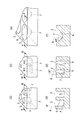
- FIG. 2 is a sectional view of a recess having various opening surface shapes.
- the angle formed by the straight line 6 that connects the outer periphery 2 of the opening surface and the outer periphery 4 of the recess 5 at a minimum distance and the perpendicular 8 to the opening surface 3 of the recess 5 is preferably in the range of ⁇ 15 ° to less than 45 °. As shown in FIGS.
- the present invention forms the concave portion so as to increase the afterglow luminance in the direction perpendicular to the light irradiation surface. Therefore, the present invention simply teaches or suggests a structure for expanding the light receiving area, for example, This is significantly different from the concave structure found in the photocatalyst field.
- the circle-equivalent diameter of the concave opening surface 3 is preferably 0.1 mm or more and 100 mm or less. If it is less than 0.1 mm, the formation of the recess 5 may be difficult, and if it exceeds 100 mm, the effect of increasing the surface area may be reduced.
- the depth of the recess 5 is preferably 0.3 to 4 times the diameter of the recess opening surface 3 in terms of a circle, and more preferably 0.3 to 3 times. If the ratio is less than 0.3 times, the effect of surface area increase is low and the effect may be reduced. If the ratio exceeds 4 times, the area increases, but the number of times the excitation light or afterglow is reflected on the inner wall surface (side surface). May increase, and the effect may reach its peak.
- FIG. 4 shows a phosphorescent phosphor ceramic 1 in which a concave portion 5 in which the shape of the opening surface 3 is square is formed on the light irradiation surface.
- the surface of the phosphorescent phosphor ceramic has a large number of recesses 5 with a constant interval length L.
- the interval length L between adjacent recesses is preferably 0.1 mm to 10 mm. If it is less than 0.1 mm, the strength of the inner wall surface 9 may be weakened, and if it exceeds 10 mm, the effect of increasing the excitation area may be reduced.
- the area ratio (S1 / S2) is 0.1, where S1 is the area of the edge 12 other than the aperture 3 and the area of the aperture 3 is S2 in the projected area (Sa) of the light-irradiated surface of the phosphor phosphor. It is preferable that If it is less than 0.1, the strength of the inner wall surface 9 may be weakened, and if it exceeds 10, the effect of increasing the excitation area may be reduced.
- the phosphorescent phosphor used in the phosphorescent phosphor ceramic of the present invention a commercially available product using zinc sulfide or an alkaline earth metal aluminate as a crystal matrix is popular. All long-lasting phosphors that can be made of ceramics made of phosphorescent phosphors are applicable.
- M is at least one element of Sr, Ca, Ba, and Mg, and MAl 2 O 4 : Eu, Dy, M 4 Al 14 O 25 : Eu, Dy, Sr 3 MgSi 2.
- Alkaline earth metal aluminates with rare earth elements having the highest afterglow brightness and excellent weather resistance are practical and preferred.
- Alkali earth metal aluminates are exemplified in Japanese Patent No. 2543825, Japanese Patent No. 3323548, etc., but in these documents, only fluorescence in powder is used.
- the phosphorescent phosphor ceramic of the present invention can also be produced by molding and sintering phosphorescent phosphor particles, but more preferably, the phosphor powder raw material powder mixture is molded so as to have a desired concave shape and fluorescent. It is advisable to carry out the soaking reaction and sintering at the same time. Existing phosphorescent phosphor particles generally have poor moldability and sinterability, and the manufacturing cost increases because the pressure during molding and the temperature required for sintering are high. On the other hand, by using a raw material powder mixture as a solid phosphor, sintering proceeds easily when a phosphorescent phosphor composition is produced by a chemical reaction during firing, so a relatively low molding pressure (0.
- Ceramics can be obtained at 1 kg / cm 2 to 500 kg / cm 2 ) or at a relatively low sintering temperature (800 ° C. to 1500 ° C., preferably 1000 ° C. to 1400 ° C.). Sintering can be performed in a non-oxidizing gas such as argon, nitrogen, carbon monoxide, or a weakly reducing gas atmosphere such as nitrogen containing hydrogen.
- the average particle diameter of each substance of the main raw material powder of the phosphorescent phosphor is preferably 0.1 ⁇ m to 10 ⁇ m. The average particle diameter is a value that can be measured by a laser diffraction method.
- the method for forming the recesses in the phosphorescent phosphor ceramic of the present invention is not particularly limited, but the time when the molded body is formed by molding with an uneven mold or by machining such as grinding or recess forming on the surface of the flat molded body Apply processing.
- the formation of the recess can be performed by drilling or the like after the flat molded body is sintered, and does not exclude such a forming method. It is also possible to combine the planar structures three-dimensionally.
- the phosphorescent phosphor ceramics of the present invention may be coated with a transparent resin on the surface or baked and coated with a transparent glass frit for the purpose of surface protection or design.
- Example 1 Comparative Example 1 ⁇ Concavity formation processing of planar structure> 640 g of alumina (average particle size: 1.2 ⁇ m), 890 g of Sr carbonate (average particle size: 2.2 ⁇ m), 22 g of oxidized Dy (average particle size: 5.7 ⁇ m), and 11 g of Eu oxide (average particle size: 6.5 ⁇ m) And 30 g of boric acid (average particle size: 500 ⁇ m) were mixed by a ball mill for 6 hours to obtain a raw material powder mixture.
- alumina average particle size: 1.2 ⁇ m
- 890 g of Sr carbonate average particle size: 2.2 ⁇ m
- 22 g of oxidized Dy average particle size: 5.7 ⁇ m
- 11 g of Eu oxide average particle size: 6.5 ⁇ m
- boric acid average particle size: 500 ⁇ m
- 150 g of this was molded into a flat plate shape (100 * 100 * 10 t) with a press pressure of 100 kg / cm 2 using a 100 mm square mold.
- Two flat molded bodies were prepared, and 81 cylindrical recesses having a diameter of 5 mm and a depth of 5 mm were formed on one upper surface portion by grinding at intervals of 5 mm. Both were placed on an alumina plate and sintered at 1300 ° C. for 3 hours (in a nitrogen atmosphere) to obtain a solid phosphorescent phosphor ceramic.
- the upper surface of both was irradiated with 5000 Lx D65 standard light for 10 minutes, and after 60 minutes after irradiation was stopped, the afterglow luminance was measured with a luminance meter (LS-100, manufactured by Konica Minolta) from the direction perpendicular to the light irradiation surface. , those recesses formed machining the 430mCd / cm 2, compared with 220mCd / cm 2 of flat plate samples showed afterglow luminance about twice.
- Comparative Example 1 is a solid phosphor fluorescent ceramic that does not grind Example 1.
- Examples 2-7, Example 13 Solid phosphorescent phosphor ceramics were obtained in the same manner as in Example 1 except that the shape and dimensions of the recesses were changed. The outer dimensions of the ceramics were all 71 * 71 * 7t, and the other dimensions and afterglow luminance were as shown in Table 1. (Dimensions are average values after sintering) (Examples 8 to 11) Solid phosphorescent phosphor ceramics were obtained in the same manner as in Example 1 except that the shape, size, and hole interval of the recesses were changed. 400 concave portions were formed.
- Example 11 had 81 pieces
- the outer dimensions of the ceramics were all 71 * 71 * 7t, and the other dimensional shapes and afterglow luminances were as shown in Table 1. (Dimensions are average values after sintering) (Example 12, Comparative Example 2) ⁇ When the phosphorescent phosphor powder is sintered> 120 g of commercially available phosphorescent phosphor powder (trade name: GLL300F SrAl2O4: Eu, Dy) manufactured by Nemoto Special Chemical Co., Ltd. was press-molded into a flat plate shape at a pressure of 1 t / cm 2 using a 76 mm square mold.
- Two flat molded bodies were prepared, and 81 cylindrical recesses having a diameter of 3.9 mm and a depth of 3.9 mm were formed on one upper surface portion by grinding at intervals of 3.9 mm. Both were placed on an alumina plate and sintered at 1450 ° C. for 3 hours (in a nitrogen atmosphere) to obtain a solid phosphorescent phosphor ceramic.
- the outer dimensions of the ceramics were 70 * 70 * 7t by sintering, and the concave and convex diameters of the concave and convex samples were an average of 3.7 mm and the depth was an average of 3.6 mm.
- the recess-formed product showed 340 mCd / cm 2 , which was about twice as long as the afterglow brightness of 180 mCd / cm 2 of the flat plate sample.
- phosphorescent phosphor ceramics that were not ground in Example 12 were used.
- the comparative example 3 is the luminous body which was not ground in the comparative example 4.
- Comparative Example 5 is a phosphorescent phosphor when the grinding process in Comparative Example 6 is not performed.
- the afterglow brightness was measured in the same manner as in Example 1, it was 140 mCd / cm 2 (Comparative Example 6) that was processed to form a recess, and a little compared with 120 mCd / cm 2 (Comparative Example 5) of the flat plate sample.
- the afterglow increasing effect due to the formation of the recess was very low compared with the solid phosphorescent ceramics such as Example 12. This is probably because the phosphorescent phosphor is present in the form of dispersed particles, and the loss due to scattering or the like is large in the reflection of excitation light and afterglow occurring on the inner surface of the recess.
Landscapes
- Chemical & Material Sciences (AREA)
- Engineering & Computer Science (AREA)
- Materials Engineering (AREA)
- Organic Chemistry (AREA)
- Ceramic Engineering (AREA)
- Inorganic Chemistry (AREA)
- Manufacturing & Machinery (AREA)
- Structural Engineering (AREA)
- Luminescent Compositions (AREA)
- Illuminated Signs And Luminous Advertising (AREA)
Abstract
深部の蛍光体を有効に活用することができる蓄光蛍光体セラミックスを提供する。 光照射表面に凹部を備えた無垢の蓄光蛍光体セラミックスであって、該凹部は、形成されていない場合に比べて受光面積を高め、かつ、前記光照射表面に垂直な方向から測定した残光輝度を高めるように形成されている無垢の蓄光蛍光体セラミックスである。
Description
本発明は、避難経路表示板や補助照明,サイン,タイル等に使用することのできる無垢の蓄光蛍光体セラミックスに関するものである。
近年、蓄光蛍光体は災害時の対策として、地下鉄構内や高層ビルなどの避難経路表示等で需要が増加しつつある。蓄光蛍光体は通常粉体として販売されており、これを透明樹脂に練り込んだり、塗料に分散させたりして成形体や表示板などの構造体として利用するのが普通である(例えば、特許文献1、2等を参照)。
また、特殊な例としては、蓄光蛍光体粉をガラス粉(フリット)と混合して数百℃でガラスを溶融して複合セラミックス構造体として利用する方法も提案されている(特許文献3、4等を参照)。
更に、蓄光蛍光体粉そのものを成形・焼結して、無垢の緻密な蓄光蛍光体セラミックスを得る方法も提案されている(特許文献5、6等を参照)。
しかしながら、これらの製品は製造工程が長く、高価な割にコストに見合った残光輝度が得られていないのが現状である。
樹脂などの有機材料中に蓄光蛍光体粒子を分散した製品は耐候性に劣り、屋外にて使用した場合、短期間で樹脂が失透したり黄ばんだりして励起光が弱められる。更に、樹脂などの有機材料は若干の吸水性がある為、雨水等が徐々に浸透して蓄光蛍光体粒子の表面に達し、蛍光体が徐々に加水分解され、蓄光性能が劣化していく。
特許文献7では、樹脂材料をシリコーン樹脂にすることにより耐候性を高めてはいるが、これとて半永久的というわけではなく、通常の樹脂材料と比較して劣化速度が数年遅くなるという程度のものである。
ガラス中に蓄光蛍光体粒子を溶融分散した複合セラミックス体の場合、耐候性については問題ないのであるが、ガラスの融点以上の高温で溶融するため、ガラスと蓄光蛍光体粒子が反応して、蓄光性能が劣化するという問題をかかえている。
更に、蓄光蛍光体粒子を樹脂やガラスなどの媒体に分散した製品は粒子表面での励起光の散乱損失が起こりやすく隠蔽性が強い為、数百ミクロン以上の深部の蛍光体は励起されずに無駄になり、充分な残光が得られない。
これらに対して、蓄光蛍光体粒子そのものを焼結することによって作られる無垢の蓄光蛍光体セラミックスは、上記の媒体分散型製品と比較して耐候性が非常に高く、また、粒子同士が焼結によって緻密な連結構造となり散乱損失が起きにくいので、残光輝度も向上する。
しかしながら、その場合でも励起光が侵入できる深さは数ミリ程度までであり、蛍光体自体の強力な励起光吸収性の為、数ミリ以上の深部に有効に励起光を届かせることはできない。これは透明性のある緻密質の焼結体であっても同様であり、やはり深部の蛍光体が有効に活用されないので、充分な残光輝度は得られない。
本発明は、上記現状に鑑み、深部の蛍光体を有効に活用することができる蓄光蛍光体セラミックスを得ることを目的とする。
本発明者等は上記問題を解決するために、輝度の向上を鋭意検討した結果、無垢の蓄光蛍光体セラミックスの表面に受光面積を高め、かつ、前記光照射表面に垂直な方向への残光放射を高めるような凹部構造を形成すると、蓄光エネルギー総量が増加し、従来の蓄光蛍光体セラミックス製品の数倍の残光輝度を示すことを発見し、本発明に至った。
本発明の要旨は、光照射表面に凹部を備えた無垢の蓄光蛍光体セラミックスであって、該凹部の内部の表面積と該凹部を規定する凸部表面(頂面)の表面積との合計の面積が前記光照射表面の投影面積に比べて大きく、かつ、前記光照射表面に垂直な方向から測定した残光輝度を高めるように前記凹部が形成されている無垢の蓄光蛍光体セラミックスである。
本発明によれば、焼結体中であるが故に粒子による励起光の散乱損失が無く、励起光が直接当たる表面積が増え、かつ、光照射表面に垂直な方向に従来蓄光製品の数倍の残光輝度を示す蓄光蛍光体セラミックス焼結体を得ることができ、これは屋外でも半永久的に使用できるほど耐候性が高く、その利用価値は極めて高い。
1 蓄光蛍光体セラミックス
2 凹部の開口面外周
3 凹部開口面
4 凹部の底面外周
5 凹部
6 凹部の開口面外周と底面外周とを最小距離で結ぶ直線
7 凹部底面
8 開口面に対する垂線
9 凹部内側壁面
12 縁部
以下、本発明を詳細に説明する。
本発明の蓄光蛍光体セラミックスは、避難経路表示板や補助照明,サイン,タイル等の製品に使用されるものである。
本発明にかかる蓄光蛍光体セラミックスは、光(可視光)照射表面に凹部を備えた無垢の蓄光蛍光体セラミックスであって、該凹部は、形成されていない場合に比べて受光面積を高め、かつ、前記光照射表面に垂直な方向から測定した残光輝度を高めるように形成されている無垢の蓄光蛍光体セラミックスである。
蓄光性構造体の表面に凹部を形成すると、開口面に垂直な方向からの見た目が同じ面積であっても、励起光が当たる表面積は増大する。これによって、励起される蓄光蛍光体の総量が増えることになり、残光の発生量が増大する。さらに、凹部の構造を工夫することによって、光照射表面に垂直な方向への出射量を増大することができる。
更に、蓄光性構造体の材質を無垢の蓄光蛍光体セラミックスにすると、粒子による励起光の散乱損失が無いので、深さ方向に於いても励起される蓄光蛍光体の総量が増えることになり、残光輝度はより強くなる。
本明細書において、「蓄光蛍光体セラミックス」が「無垢」であるとは、実質的に蓄光蛍光体組成成分のみからなることを意味する。「実質的に蓄光蛍光体組成成分のみ」とは、蓄光蛍光体組成成分に加えて、蛍光体の合成時に少量加えることのある反応促進剤であるフラックス成分を任意成分として含みうることを意味する。
よって、本発明にかかる蓄光蛍光体セラミックスは、全組成中に80モル%~100モル%、好ましくは90~100モル%の蛍光体成分を含み、任意成分としてフラックス成分を全組成中0~20モル%、好ましくは0~10モル%含みうるものである。
凹部のサイズは、形成されていない場合に比べて受光面積を高め、かつ、前記光照射表面に垂直な方向から測定した残光輝度を高めることが可能であれば特に限定されないが、ひとつの目安として、セラミックスの光照射面の面積、具体的には凹部内の表面積と凸部平面の合計の幾何学的面積をS、表面の投影面積(=平面部分の面積)をSaとしたとき、(S/Sa)(つまり凹凸による表面積の増大率)で表すことができる。Saは表面に凹凸が無く、全く平滑であるときの面積を意味する。増大した表面積Sには、意図しない表面の単なる粗さによる増大分は含まない。この「粗さ」とは、制約するわけではないが大ざっぱに言って、粗さ計で測定して最大粗さ(Hmax)が1mm未満程度の粗面を意味する。(S/Sa)は1.0より大、好ましくは1.2以上、10未満が良く、より好ましくは、1.5以上8未満が好ましい。凹凸が少ない場合には効果が薄く、10以上では、効果のわりに、形成コストが高くなる場合がある。
上記凹凸による表面積の増大率(S/Sa)はマイクロスコープ等を用いて凹部の立体像寸法を測定し、コンピュータ等による演算処理にて得られた値である。具体例として、例えば凹部形状が逆円錐状および逆円錐柱状の場合、(S/Sa)は、図5に示すように3次元測定機で得られた角度値(θ)、マイクロメータで得られた開口径値(D1)、デプスメータで得られた深さ値(L2)に基づいて、凹部の底面積および円錐柱の側面積を算出し、下記計算式によって計算することができる。
d1=D1/2/SINθ
D2=D1-2*TANθ*L2
d2=D2/2/SINθ
S/Sa=[Sa-π*(D1/2)2*穴個数+{π*(D1/2*d1-D2/2*d2)+π*(D2/2)2}*穴個数]/Sa
さらに上記凹部は、底面を有し、開口面の形状、凹部底面の形状、ならびに、前記開口面に平行な凹部断面の形状が、互いに合同形状または相似形状であることが好ましい。
開口面の形状としては特に限定されないが、円形、または、多角形(四角形、六角形)であることが好ましい。
図1に蓄光蛍光体セラミックス1の一態様の模式的斜視図を示す。図1では、セラミックス表面に開口面3の形状が円形であり、底面7もまた開口面と同径の円形である凹部5が表面から垂直な方向に形成されている。
開口面の形状、凹部底面の形状、ならびに、前記開口面に平行な凹部断面の形状が、互いに合同形状または相似形状でないような形状、例えば、断面形状が不規則な起伏や、図3に示すように底面を有しない波板状の凹部形状の場合でも、残光の発生量自体は増加するものの、凹部内側壁面(側面)9で反射するときに開口面3に垂直な方向以外の方向に逃げていく残光が多く、若干効果が薄れる場合がある。
残光輝度を上げるために、凹部5の底面7はもちろん、凹部5の内壁(側面)9も蓄光性であることが好ましい。図2に種々の開口面形状を有する凹部断面図示す。凹部5の開口面外周2と底面外周4とを最小距離で結ぶ直線6と、凹部開口面3に対する垂線8とがなす角度は、-15°以上45°未満の範囲であることが好ましい。図2(c)および(d)に示すように-15°未満では凹部からの残光の凹部底面7に垂直な方向8への取り出し効率が悪くなる場合があり、図2(e)および(f)に示すように45°以上であると、凹部底面7に垂直な方向8以外の方向に逃げる残光が多く、効果が薄れる場合がある。このように本発明は、光照射表面に垂直な方向への残光輝度を高めるように凹部を形成するものであるので、単に受光面積を広げる構造を教示、示唆するような他分野、例えば、光触媒分野等にみられる凹部構造とは著しく相違する。
凹部開口面3の円換算直径は、0.1mm以上、100mm以下であることが好ましい。0.1mm未満であると、凹部5の形成が難しくなる場合があり、100mmを超えると、表面積の増大効果が低くなる場合がある。
凹部5の深さは、凹部開口面3の円換算直径の0.3~4倍であることが好ましく、さらに0.3~3倍であることが好ましい。0.3倍未満であると表面積の増大割合が低いので効果が薄くなる場合があり、4倍を超えると、面積は増大するものの、励起光や残光が内壁面(側面)に反射する回数も増えるので、効果が頭打ちになる場合がある。
図4は、光照射表面に開口面3の形状が正方形である、凹部5を形成した蓄光蛍光体セラミックス1を示す。図4から明らかなように、蓄光蛍光体セラミックスの表面には、凹部5が一定の間隔長さLを隔てて多数個あることが好ましい。
隣接する凹部の間隔長さLは、0.1mm~10mmであることが好ましい。0.1mm未満であると、内壁面9の強度が弱くなる場合があり、10mmを超えると、励起面積の増大効果が低くなる場合がある。
また蓄光蛍光体セラミックスの光照射表面の投影面積(Sa)に占める開口面3以外の縁部12の面積をS1、開口面3の面積をS2として、面積比(S1/S2)が 0.1~10 であることが好ましい。0.1未満であると、内壁面9の強度が弱くなる場合があり、10を超えると、励起面積の増大効果が低くなる場合がある。
なお、本発明の蓄光蛍光体セラミックスに用いられる蓄光蛍光体としては、市販品として硫化亜鉛やアルカリ土類金属のアルミン酸塩を結晶母体とするものがポピュラーであるが、焼結によって実質的に蓄光蛍光体からなるセラミックスにできる長残光性蛍光体であれば全て適用可能である。
かかる蓄光蛍光体としては、MがSr、Ca、Ba、Mgのうち少なくともいずれか1つの元素で、MAl2O4:Eu,Dy、M4Al14O25:Eu,Dy、Sr3MgSi2O8 :Eu,Dy,Cl、Y2O2S:Eu,Mg,Ti、ZnS:Cu、(Ca,Sr)S:Bi、(Zn,Cd)S:Cu型などが具体例として挙げられるが、これらに限定されるものではない。
現状では、最も残光輝度が高く耐候性にも優れる希土類元素を付括したアルカリ土類金属のアルミン酸塩が実用的で好ましい。アルカリ土類金属のアルミン酸塩は、特許第2543825号,特許第3232548号などに例示されているが、これらの文献においては粉体での蛍光を利用するに留まっている。
本発明の蓄光蛍光体セラミックスは、蓄光蛍光体粒子を成形・焼結することによっても製造できるが、より好ましくは、蓄光蛍光体の原料粉末混合物を所望の凹部形状を有するように成形し、蛍光体化反応と焼結を同時に行うとよい。既存の蓄光蛍光体粒子は一般的に成形性や焼結性が悪く、成形時の圧力や焼結に必要な温度が高くなるので製造コストが高くなる。これに対し、原料粉末混合物で無垢の蛍光体にすることより、焼成時の化学反応によって蓄光蛍光体組成物が生成される際に焼結が容易に進むので、比較的低い成形圧(0.1kg/cm2~500kg/cm2)や比較的低い焼結温度(800℃~1500℃、好ましくは1000℃~1400℃)にてセラミックスを得ることが出来る。
焼結は、アルゴン、窒素、一酸化炭素等の非酸化性ガス、もしくは水素を含んだ窒素等の弱還元性ガス雰囲気下で行うことができる。
蓄光蛍光体の主原料粉末の各物質の平均粒子径は、0.1μm~10μmであることが好ましい。上記平均粒子径は、レーザー回折法によって測定し得られる値である。
本発明の蓄光蛍光体セラミックスにおける凹部の形成方法は特に限定しないが、凹凸を有する型による成形や、平面成形体の表面に研削や凹部形成加工等の機械加工等により、成形体として作成する時点で加工処理を施す。凹部形成は平面成形体を焼結した後にドリル加工等によって行うことも可能であり、かかる形成方法を排除するものではない。また、平面構造体を3次元的に組み合わせることによっても可能である。
本発明の蓄光蛍光体セラミックスは、表面保護やデザイン上の目的でその表面に透明樹脂をコーティングしたり、透明なガラスフリットを焼付けコーティングしてもよい。
以下、本発明の実施例を説明するが、本発明はこれによって限定されない。
(実施例1)(比較例1)<平面構造体の凹部形成加工>
アルミナ640g(平均粒子径:1.2μm)と炭酸Sr 890g(平均粒子径:2.2μm)と酸化Dy 22g(平均粒子径:5.7μm)と酸化Eu 11g(平均粒子径:6.5μm)とホウ酸30g(平均粒子径:500μm)をボールミルで6hr混合し、原料粉末混合物を得た。
この150gを100mm角の金型を用いて100kg/cm2のプレス圧で平板状(100*100*10t)に成形した。平板状の成形体は2つ作成し、1つの上面部には直径5mm、深さ5mmの円柱状の凹部を5mm間隔で研削加工によって81個形成した。両者をアルミナ板上に置いて、1300℃にて3時間(窒素雰囲気下)焼結し、無垢の蓄光蛍光体セラミックスを得た。
セラミックスの寸法は焼結によって71*71*7tとなり凹凸サンプルの凹部穴径は平均3.6mm、深さは平均3.7mmであった。よって、(S/Sa)=(71*71+3.6*3.14*3.7*81)/(71*71)=1.67となる。
両者の上面部に5000LxのD65標準光を10分間照射し、照射をやめて60分後に、輝度計(コニカミノルタ社製LS-100)に光照射表面に垂直な方向から残光輝度を測定したところ、凹部形成加工したものは430mCd/cm2と、平板サンプルの220mCd/cm2と比べて、約2倍の残光輝度を示した。
なお、比較例1は、実施例1を研削加工しない無垢の蓄光蛍光体セラミックスである。

(実施例2~7、実施例13)凹部の形状、寸法を変えたこと以外は実施例1と同様にして、無垢の蓄光蛍光体セラミックスを得た。セラミックスの外寸法は全て71*71*7tとなり、その他の寸法形状及び残光輝度は表1に示した通りであった。(寸法は焼結後の平均数値)
(実施例8~11)凹部の形状、寸法と穴間隔とを変えたこと以外は実施例1と同様にして、無垢の蓄光蛍光体セラミックスを得た。凹部は400個形成した。(実施例11は81個。)セラミックスの外寸法は全て71*71*7tとなり、その他の寸法形状及び残光輝度は表1に示した通りであった。(寸法は焼結後の平均数値)
(実施例12、比較例2)<蓄光蛍光体粉を焼結した場合>
市販の蓄光蛍光体粉(根本特殊化学(株)製 商品名:GLL300F SrAl2O4:Eu,Dy)120gを76mm角の金型を用いて1t/cm2の圧力で平板状にプレス成形した。平板状の成形体は2つ作成し、1つの上面部には直径3.9mm、深さ3.9mmの円柱状の凹部を3.9mm間隔で研削加工によって81個形成した。両者をアルミナ板上に置いて、1450℃にて3時間(窒素雰囲気下)焼結し、無垢の蓄光蛍光体セラミックスを得た。セラミックスの外寸法は焼結によって70*70*7tとなり凹凸サンプルの凹部穴径は平均3.7mm、深さは平均3.6mmであった。残光輝度を実施例1と同様にして測定したところ、凹部形成加工したものは340mCd/cm2と、平板サンプルの180mCd/cm2と比べて、約2倍の残光輝度を示した。
比較例2は、実施例12において、研削加工しない蓄光蛍光体セラミックスを用いた。
(比較例3,4)<蓄光蛍光体粉をガラスに分散した場合>
市販の蓄光蛍光体粉(根本特殊化学(株)製 商品名:GLL300F 前出)47gを無鉛ガラスフリット47gと混合し、固いペースト状になるように水を加えた。得られたペーストを78mm角の金型を用いて平板状に成形・乾燥した。平板状の成形体は2つ作成し、1つの上面部には直径4.0mm、深さ4.0mmの円柱状の凹部を4.0mm間隔で研削加工によって81個形成した。両者を、アルミナ粉を塗布したアルミナ板上に置いて、700℃で60分間(窒素雰囲気下)焼成し、ガラス複合のアモルファスタイプの蓄光セラミックスを得た。セラミックスの寸法は焼成によって70*70*7tとなり凹凸サンプルの凹部穴径は平均3.6mm、深さは平均3.6mmであった。残光輝度を実施例1と同様にして測定したところ、凹部形成加工したものは110mCd/cm2(比較例4)と、平板サンプルの90mCd/cm2(比較例3)と比べて、若干の増大が見られたものの、無垢の結晶組織を有する実施例12の蓄光蛍光体セラミックスと比較して凹部形成による残光増大効果は非常に低いものであった。原因としては、蓄光蛍光体が分散粒子の状態で存在するために、凹部内面で起こる励起光や残光の反射において散乱等による損失が大きい為と考えられる。なお、比較例3は、比較例4において研削加工しなかった蓄光体である。
(比較例5,6)<蓄光蛍光体粉を樹脂に分散した場合>
市販の蓄光蛍光体粉(根本特殊化学(株)製 商品名:GLL300F 前出)25gを透明シリコーン樹脂(信越化学工業(株)製 商品名:KE-109A,B(1:1)混合物)50gに分散混合し、その内の50gを70mm角の金型に鋳込んで80℃で1時間加熱硬化成形した。平板状の成形体は2つ作成し、外寸法は70*70*7tであった。そして、1つの上面部には直径3.6mm、深さ3.7mmの円柱状の凹部を3.6mm間隔で研削加工によって81個形成した。
比較例5は、比較例6における研削加工をしなかった場合の蓄光蛍光体である。
残光輝度を実施例1と同様にして測定したところ、凹部形成加工したものは140mCd/cm2(比較例6)と、平板サンプルの120mCd/cm2(比較例5)と比べて、若干の増大が見られたものの、実施例12等の無垢の蓄光蛍光体セラミックスと比較して凹部形成による残光増大効果は非常に低いものであった。原因としては、蓄光蛍光体が分散粒子の状態で存在するために、凹部内面で起こる励起光や残光の反射において散乱等による損失が大きい為と考えられる。
Claims (6)
- 光照射表面に凹部を備えた無垢の蓄光蛍光体セラミックスであって、
該凹部は、形成されていない場合に比べて受光面積を高め、かつ、前記光照射表面に垂直な方向から測定した残光輝度を高めるように形成されている無垢の蓄光蛍光体セラミックス。 - 前記凹部は、底面を有し、該凹部の開口面の形状、底面の形状、ならびに、前記開口面に平行な凹部断面の形状が、互いに合同形状または相似形状であることを特徴とする請求項1に記載の無垢の蓄光蛍光体セラミックス。
- 前記凹部の開口面外周と底面外周とを最小距離で結ぶ直線と、前記凹部の開口面に対する垂線とがなす角度が、-15°以上45°未満の範囲であることを特徴とする請求項2に記載の無垢の蓄光蛍光体セラミックス。
- 該凹部の開口面から該凹部の最も深い位置までの最短距離が、前記凹部開口面の円換算直径の0.3倍以上4倍以下であることを特徴とする請求項1ないし3のいずれかに記載の無垢の蓄光蛍光体セラミックス。
- 該凹部の開口面から該凹部の最も深い位置までの最短距離が、0.3倍以上3倍以下であることを特徴とする請求項4に記載の無垢の蓄光蛍光体セラミックス。
- 蓄光蛍光体の原料粉末混合物を、光照射する面に凹部を形成するように成形し、反応と焼結を同時に行うことよりなる無垢の蓄光蛍光体セラミックスの製造方法。
Priority Applications (1)
| Application Number | Priority Date | Filing Date | Title |
|---|---|---|---|
| JP2010543016A JP5389823B2 (ja) | 2008-12-19 | 2009-12-18 | 無垢の蓄光蛍光体セラミックス |
Applications Claiming Priority (2)
| Application Number | Priority Date | Filing Date | Title |
|---|---|---|---|
| JP2008-323562 | 2008-12-19 | ||
| JP2008323562 | 2008-12-19 |
Publications (1)
| Publication Number | Publication Date |
|---|---|
| WO2010071203A1 true WO2010071203A1 (ja) | 2010-06-24 |
Family
ID=42268870
Family Applications (1)
| Application Number | Title | Priority Date | Filing Date |
|---|---|---|---|
| PCT/JP2009/071169 Ceased WO2010071203A1 (ja) | 2008-12-19 | 2009-12-18 | 無垢の蓄光蛍光体セラミックス |
Country Status (2)
| Country | Link |
|---|---|
| JP (1) | JP5389823B2 (ja) |
| WO (1) | WO2010071203A1 (ja) |
Cited By (1)
| Publication number | Priority date | Publication date | Assignee | Title |
|---|---|---|---|---|
| JP2015131912A (ja) * | 2014-01-14 | 2015-07-23 | 国立大学法人宇都宮大学 | 透明蛍光発光物体及びその製造方法 |
Citations (6)
| Publication number | Priority date | Publication date | Assignee | Title |
|---|---|---|---|---|
| JPS59120679A (ja) * | 1982-12-27 | 1984-07-12 | Sumitomo Electric Ind Ltd | イオンビ−ムモニタ−用高輝度発光体およびその製造法 |
| JPH08202301A (ja) * | 1995-01-30 | 1996-08-09 | Rhythm Watch Co Ltd | 蓄光型発光体 |
| JPH11180211A (ja) * | 1997-12-24 | 1999-07-06 | Aisin Seiki Co Ltd | 蛍光体 |
| JP2005105116A (ja) * | 2003-09-30 | 2005-04-21 | Seiko Epson Corp | 蓄光性蛍光体の焼結体製造方法および射出成型用原料ペレット製造方法 |
| JP3115069U (ja) * | 2005-07-25 | 2005-11-04 | 岡谷電機産業株式会社 | 放電管 |
| JP2008047376A (ja) * | 2006-08-11 | 2008-02-28 | Seikoh Giken Co Ltd | 携帯用照明装置 |
-
2009
- 2009-12-18 JP JP2010543016A patent/JP5389823B2/ja not_active Expired - Fee Related
- 2009-12-18 WO PCT/JP2009/071169 patent/WO2010071203A1/ja not_active Ceased
Patent Citations (6)
| Publication number | Priority date | Publication date | Assignee | Title |
|---|---|---|---|---|
| JPS59120679A (ja) * | 1982-12-27 | 1984-07-12 | Sumitomo Electric Ind Ltd | イオンビ−ムモニタ−用高輝度発光体およびその製造法 |
| JPH08202301A (ja) * | 1995-01-30 | 1996-08-09 | Rhythm Watch Co Ltd | 蓄光型発光体 |
| JPH11180211A (ja) * | 1997-12-24 | 1999-07-06 | Aisin Seiki Co Ltd | 蛍光体 |
| JP2005105116A (ja) * | 2003-09-30 | 2005-04-21 | Seiko Epson Corp | 蓄光性蛍光体の焼結体製造方法および射出成型用原料ペレット製造方法 |
| JP3115069U (ja) * | 2005-07-25 | 2005-11-04 | 岡谷電機産業株式会社 | 放電管 |
| JP2008047376A (ja) * | 2006-08-11 | 2008-02-28 | Seikoh Giken Co Ltd | 携帯用照明装置 |
Cited By (1)
| Publication number | Priority date | Publication date | Assignee | Title |
|---|---|---|---|---|
| JP2015131912A (ja) * | 2014-01-14 | 2015-07-23 | 国立大学法人宇都宮大学 | 透明蛍光発光物体及びその製造方法 |
Also Published As
| Publication number | Publication date |
|---|---|
| JPWO2010071203A1 (ja) | 2012-05-31 |
| JP5389823B2 (ja) | 2014-01-15 |
Similar Documents
| Publication | Publication Date | Title |
|---|---|---|
| CN102782089B (zh) | 发光陶瓷层压制件及其制造方法 | |
| JP5049336B2 (ja) | エレクトロルミネセントデバイス | |
| EP2513247B1 (en) | Light emitting diode device with luminescent material | |
| TWI538981B (zh) | 具有摻雜濃度梯度的發光性陶瓷材料、其製造和使用方法 | |
| JP6140766B2 (ja) | 発光デバイス用のセラミック体 | |
| EP2678404B1 (en) | Light emitting composite with phosphor components | |
| JP5551079B2 (ja) | 多孔質蓄光蛍光体セラミックス | |
| JP5356822B2 (ja) | 向上したCaAlSiN光変換材料を有する発光デバイス | |
| KR102059425B1 (ko) | 희토류 원소가 확산된 산화물 세라믹 형광 재료 | |
| TW200808117A (en) | Light-emitting device | |
| TW201942336A (zh) | 螢光體及使用其之發光裝置 | |
| CN107586127B (zh) | 陶瓷复合体以及含有其的投影仪用荧光体和发光设备 | |
| JP5765526B2 (ja) | 光反射基材およびそれを用いた発光デバイス | |
| JP2012062444A (ja) | 緑色蛍光体 | |
| CN112441817A (zh) | 荧光陶瓷及其制备方法、光源装置 | |
| JP5389823B2 (ja) | 無垢の蓄光蛍光体セラミックス | |
| JP6989307B2 (ja) | セラミックス複合体、並びにこれを含むプロジェクター用蛍光体及び発光デバイス | |
| JP5733984B2 (ja) | 散乱度が小さいled用セラミック材料及びその製造方法 | |
| EP4033276B1 (en) | Wavelength converter | |
| KR20230001983A (ko) | 파장 변환 부재 및 이를 포함하는 발광장치 | |
| WO2020147516A1 (zh) | 复相荧光陶瓷及其制备方法 | |
| El Kazazz et al. | Production of violet-blue emitting phosphors via solid state reaction and their uses in outdoor glass fountain | |
| JP2012211229A (ja) | 緑色蛍光体 | |
| CN102471685A (zh) | 发绿光材料 | |
| KR20140092509A (ko) | 발광특성을 가지는 금속플레이트의 제조방법 및 그 플레이트 |
Legal Events
| Date | Code | Title | Description |
|---|---|---|---|
| 121 | Ep: the epo has been informed by wipo that ep was designated in this application |
Ref document number: 09833505 Country of ref document: EP Kind code of ref document: A1 |
|
| WWE | Wipo information: entry into national phase |
Ref document number: 2010543016 Country of ref document: JP |
|
| NENP | Non-entry into the national phase |
Ref country code: DE |
|
| 122 | Ep: pct application non-entry in european phase |
Ref document number: 09833505 Country of ref document: EP Kind code of ref document: A1 |