WO2010070911A1 - 可変容量圧縮機のローターと斜板のリンク機構 - Google Patents
可変容量圧縮機のローターと斜板のリンク機構 Download PDFInfo
- Publication number
- WO2010070911A1 WO2010070911A1 PCT/JP2009/006964 JP2009006964W WO2010070911A1 WO 2010070911 A1 WO2010070911 A1 WO 2010070911A1 JP 2009006964 W JP2009006964 W JP 2009006964W WO 2010070911 A1 WO2010070911 A1 WO 2010070911A1
- Authority
- WO
- WIPO (PCT)
- Prior art keywords
- swash plate
- rotor
- arm
- drive shaft
- pin
- Prior art date
- Legal status (The legal status is an assumption and is not a legal conclusion. Google has not performed a legal analysis and makes no representation as to the accuracy of the status listed.)
- Ceased
Links
Images
Classifications
-
- F—MECHANICAL ENGINEERING; LIGHTING; HEATING; WEAPONS; BLASTING
- F04—POSITIVE - DISPLACEMENT MACHINES FOR LIQUIDS; PUMPS FOR LIQUIDS OR ELASTIC FLUIDS
- F04B—POSITIVE-DISPLACEMENT MACHINES FOR LIQUIDS; PUMPS
- F04B27/00—Multi-cylinder pumps specially adapted for elastic fluids and characterised by number or arrangement of cylinders
- F04B27/08—Multi-cylinder pumps specially adapted for elastic fluids and characterised by number or arrangement of cylinders having cylinders coaxial with, or parallel or inclined to, main shaft axis
- F04B27/10—Multi-cylinder pumps specially adapted for elastic fluids and characterised by number or arrangement of cylinders having cylinders coaxial with, or parallel or inclined to, main shaft axis having stationary cylinders
- F04B27/1036—Component parts, details, e.g. sealings, lubrication
- F04B27/1054—Actuating elements
- F04B27/1072—Pivot mechanisms
Definitions
- the present invention relates to a link mechanism between a rotor and a swash plate of a variable capacity compressor.
- a link mechanism that includes an arm that engages with the lens is disclosed in Patent Document 1 and the like.
- the engaging portion between the arm and the swash plate is formed in the sandwiched portion formed by one of the arm or the swash plate, the pair of sandwiched portions formed by the other of the arm or the swash plate, and the sandwiched portion.
- the center portion is press-fitted and fixed to the formed through-hole, and the first pin is fitted to the pair of through-holes formed in the holding portion so that both ends are slidable, and the engagement portion between the arm and the rotor is A clamped portion formed by one of the arm or the rotor, a pair of clamped portions formed by the other of the arm or the rotor, and a central portion is press-fitted and fixed in a through hole formed in the clamped portion and formed in the clamped portion 2.
- a link mechanism having a second pin that is slidably fitted at both ends into a pair of formed through holes has been used.
- the fitting portion between the first pin and the sandwiching portion and the fitting portion between the second pin and the sandwiching portion conventionally have a constant diameter and a constant diameter that fits into the through hole. And was formed by pins. JP 2002-188565 A
- a link mechanism that connects, a piston that is reciprocated by a drive shaft that rotates via a swash plate, and a cylinder block that has a bore into which the piston is slidably inserted.
- the link mechanism is a central axis of the drive shaft And the top dead center of the swash plate engage with the swash plate so as to be rotatable about a first axis perpendicular to the plane and engage with the rotor so as to be rotatable about a second axis perpendicular to the plane.
- the point of application of the resultant force of the compression reaction force on the swash plate is in the vicinity of the top dead center of the swash plate and is formed by the center axis of the drive shaft and the top dead center of the swash plate Swash plate rotation direction slightly forward That.
- the engaging portion between the arm and the swash plate is formed in the sandwiched portion formed by one of the arm or the swash plate, the pair of sandwiched portions formed by the other of the arm or the swash plate, and the sandwiched portion.
- the center portion is press-fitted and fixed to the through hole, and the first pin is fitted in a pair of through holes formed in the holding portion so that both ends are slidable.
- the engaging portion between the arm and the rotor is the arm Alternatively, a sandwiched portion formed by one of the rotors, a pair of sandwiched portions formed by the other of the arm or the rotor, and a central portion are press-fitted and fixed in a through hole formed in the sandwiched portion and formed in the sandwiched portion.
- the compression reaction force against the swash plate in the fitting portion between the first pin and the sandwiching portion will receive most of the compression reaction force
- the fitting portion between the second pin and the clamping portion the fitting portion of the force applied point side of the resultant force of the compression reaction force against the swash plate will receive most of the compression reaction force.
- the fitting portion between the first pin and the sandwiching portion and the fitting portion between the second pin and the sandwiching portion are conventionally a through-hole having a constant diameter and a pin having a constant diameter that fits into the through-hole.
- the present invention has been made in view of the above problems, and includes a drive shaft, a rotor fixed to the drive shaft, a swash plate that is supported by the drive shaft so as to be capable of changing the inclination angle, and a drive shaft that rotates through the swash plate.
- variable capacity compressor comprising a piston reciprocated by a cylinder and a cylinder block having a bore into which the piston is slidably inserted, while allowing the rotor and the swash plate to move around the drive shaft while allowing the tilt angle of the swash plate to vary.
- a link mechanism that is connected so as not to be relatively rotatable, and is engaged with the swash plate so as to be rotatable about a first axis perpendicular to a plane formed by the center axis of the drive shaft and the top dead center of the swash plate.
- An arm that engages with the rotor so as to be rotatable about a second axis perpendicular to the plane is provided, and an engaging portion between the arm and the swash plate includes a sandwiched portion formed by one of the arm and the swash plate, an arm or a slant A pair of clamping parts formed by the other side of the plate and the clamped parts
- the center portion is press-fitted and fixed to the through-hole formed in the first and second pins slidably fitted into a pair of through-holes formed in the holding portion, and the arm and the rotor are engaged with each other.
- the portion includes a sandwiched portion formed by one of the arm or the rotor, a pair of sandwiched portions formed by the other of the arm or the rotor, and a center portion that is press-fitted and fixed in a through hole formed in the sandwiched portion.
- An object of the present invention is to provide means for suppressing wear of a link mechanism in a link mechanism having a second pin that is slidably fitted into a pair of through-holes formed at both ends.
- a drive shaft, a rotor fixed to the drive shaft, a swash plate supported by the drive shaft so as to be capable of changing the tilt angle, and a drive shaft rotating through the swash plate are provided.
- a variable capacity compressor having a piston that is driven reciprocally and a cylinder block having a bore in which the piston is slidably inserted, while allowing the rotor and the swash plate to move relative to each other around the drive shaft while allowing the tilt angle of the swash plate to vary.
- a link mechanism that is non-rotatably connected, and engages the swash plate so as to be rotatable about a first axis perpendicular to a plane formed by the center axis of the drive shaft and the top dead center of the swash plate, and the plane And an engaging portion between the arm and the swash plate, a clamped portion formed by one of the arm or the swash plate, an arm or the swash plate A pair of clamping parts formed by the other of the The center portion is press-fitted and fixed to the through-hole formed in the first and second pins slidably fitted into a pair of through-holes formed in the holding portion, and the arm and the rotor are engaged with each other.
- the portion includes a sandwiched portion formed by one of the arm or the rotor, a pair of sandwiched portions formed by the other of the arm or the rotor, and a center portion that is press-fitted and fixed in a through hole formed in the sandwiched portion.
- the through hole shape of the holding portion and the through hole of the fitting portion on the application point side of the resultant force of the compression reaction force against the swash plate Since the pin shape to be fitted to the taper shape is used, even if the fitting portion receives most of the compression reaction force, the compression reaction force is perpendicular to the sliding contact surface at the sliding contact portion between the pin and the hole. And the tangential direction component, and the surface pressure of the slidable contact surface is reduced as compared with the conventional case. As a result, wear of the engaging portion between the arm of the link mechanism and the swash plate is suppressed as compared with the conventional case.
- the fitting portion between the second pin and the sandwiching portion in the fitting portion between the second pin and the sandwiching portion, the fitting portion on the side of the application point of the resultant force of the compression reaction force on the swash plate, and the through hole shape of the sandwiching portion and the through hole
- the pin shape to be fitted is a taper shape.
- a link mechanism that is coupled so as not to be relatively rotatable, a piston that is reciprocally driven by a drive shaft that rotates via a swash plate, and a cylinder block that has a bore into which the piston is slidably inserted.
- the swash plate engagee the swash plate to be rotatable about a first axis perpendicular to the plane formed by the center axis of the drive shaft and the top dead center of the swash plate, and to be rotatable about a second axis perpendicular to the plane.
- the arm and the swash plate are engaged with each other by a clamped portion formed by one of the arm or the swash plate and a pair of sandwiched portions formed by the other of the arm or the swash plate.
- the center part is press-fitted into the through hole formed in the clamped part.
- a first pin whose both ends are slidably fitted in a pair of through-holes formed in the holding portion, and the engaging portion between the arm and the rotor is a cover formed by one of the arm or the rotor.
- the clamping part, the pair of clamping parts formed by the other of the arm or the rotor, and the center part are press-fitted and fixed in the through holes formed in the clamped part, and both ends are formed in the pair of through holes formed in the clamping part.
- variable capacity compressor having a second pin that is slidably fitted, wherein the fitting portion on the force application point side of the resultant force of the compression reaction force on the swash plate in the fitting portion between the first pin and the sandwiching portion
- the variable capacity compressor is characterized in that the through hole shape of the sandwiching portion and the pin shape fitted into the through hole are tapered.
- variable capacity compressor in the fitting portion between the first pin and the sandwiching portion, the through hole shape of the sandwiching portion of the fitting portion on the side where the resultant force of the compression reaction force against the swash plate is applied, and Since the pin shape fitted into the through hole is tapered, the compression reaction force is perpendicular to the sliding contact surface at the sliding contact portion between the pin and the hole even if the fitting portion receives most of the compression reaction force. Dispersed into the directional component and the tangential component, the surface pressure of the slidable contact surface is reduced as compared with the conventional case. As a result, wear of the engaging portion between the arm of the link mechanism and the swash plate is suppressed as compared with the conventional case.
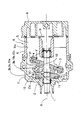
- 1 is a side sectional view of a variable capacity swash plate compressor including a rotor-swash plate link mechanism according to an embodiment of the present invention.
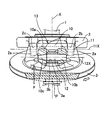
- 1 is an external perspective view of a link mechanism between a rotor and a swash plate of a variable capacity swash plate compressor according to an embodiment of the present invention.
- variable capacity swash plate compressor A includes a drive shaft 1, a rotor 2 fixed to the drive shaft 1, and a swash plate 3 supported on the drive shaft 1 so as to be capable of varying the tilt angle.
- a piston 5 moored to the swash plate 3 via a pair of shoes 4 sandwiching the peripheral edge portion of the swash plate 3 is slidably fitted to a bore 6a formed in the cylinder block 6.
- a front housing 7 that houses the drive shaft 1, the rotor 2, and the swash plate 3 is disposed.
- a cylinder head 8 that forms a suction chamber and a discharge chamber is disposed.
- a valve plate 9 is held between the cylinder block 6 and the cylinder head 8.
- the cylinder block 6, the front housing 7, the cylinder head 8, and the valve plate 9 are assembled together.
- the drive shaft 1 is rotatably supported by a front housing 7 and a cylinder block 6.
- circular through holes 2 b and 2 c are formed in a pair of rotor arms 2 a extending from the rotor 2 toward the swash plate 3.
- the circular through holes 2b and 2c extend coaxially and perpendicularly to a plane formed by the center axis X of the drive shaft 1 and the top dead center P of the swash plate 3.
- a circular through hole 3b is formed in a single swash plate arm 3a extending from the swash plate 3 toward the rotor 2.
- the circular through hole 3b extends perpendicular to a plane formed by the central axis X of the drive shaft 1 and the top dead center P of the swash plate 3.
- a link arm 10 for connecting the rotor arm 2a and the swash plate arm 3a is provided.
- a circular through hole 10a is formed at one end of the link arm 10
- a circular through hole 10b is formed at one end of the other end of the link arm 10 divided into two branches
- a funnel-shaped circular tapered through hole 10c is formed at the other.
- the diameter of the circular tapered through hole 10c decreases toward the direction away from the circular through hole 10b.
- the circular through hole 10b and the funnel-shaped circular tapered through hole 10c extend coaxially.
- the pair of rotor arms 2a sandwich the one end of the link arm 10, and the other end of the link arm 10 divided into two branches sandwiches the swash plate arm 3a.
- the central portion of the pin 11 having a constant diameter over the entire length is press-fitted and fixed in the circular through hole 10a, and both ends are fitted in the circular through holes 2b and 2c so as to be slidable relative to each other.
- a central axis 11X of the pin 11 extends perpendicular to a plane formed by the central axis X of the drive shaft 1 and the top dead center P of the swash plate 3.
- the center portion of the pin 12 is press-fitted and fixed in the circular through hole 3b, and one end portion having the same diameter as the center portion is fitted in the circular through hole 10b so as to be slidable relative to the other end portion. Is fitted to the circular tapered through hole 10c in a slidable manner.
- a central axis 12X of the pin 12 extends perpendicular to a plane formed by the central axis X of the drive shaft 1 and the top dead center P of the swash plate 3.
- a link mechanism 13 is formed by the rotor arm 2 a, the swash plate arm 3 a, the link arm 10, and the pins 11 and 12. The link mechanism 13 connects the rotor 2 and the swash plate 3 around the drive shaft 1 so as not to rotate relative to each other while allowing a change in the tilt angle of the swash plate 3.
- variable capacity swash plate compressor A the swash plate 3 rotates in the direction of the white arrow in FIG.
- the piston 5 reciprocates in the bore 6a, sucks gas into the bore 6a, and compresses the gas in the bore 6a.
- a compression reaction force generated when the gas in the bore 6a is compressed is applied to the swash plate 3 and transmitted from the swash plate 3 to the link arm 10 through the pin 12, and from the link arm 10 to the rotor through the pin 11. 2 and transmitted from the rotor 2 to the front housing 7.
- the resultant force F of the compression reaction force against the swash plate 3 is in the vicinity of the top dead center P of the swash plate and the center of the drive shaft 1. With respect to the plane formed by the axis X and the top dead center P of the swash plate 3, it is slightly in front of the swash plate rotation direction. As a result, in the sliding fitting portion between the other end portion of the pin 12 and the link arm 10 which is divided into two forks, the sliding fitting portion on the application point side of the resultant force F of the compression reaction force against the swash plate 3 is compressed. You will receive most of the power.
- the applied force of the resultant force F of the compression reaction force on the swash plate 3 in the sliding fitting portion between the pin 12 and the other end portion of the link arm 10 which is divided into two forks. Since the shape of the link arm through hole 10c and the shape of the other end of the pin 12 fitted into the through hole of the point side fitting portion are tapered, the fitting portion has a large portion of the compression reaction force.
- the compression reaction force is dispersed into the vertical component and the tangential component with respect to the sliding contact surface at the sliding contact portion between the other end portion of the pin 12 and the through hole 10c, and the surface pressure of the sliding contact surface is conventionally increased. Compared to decrease. As a result, wear of the engaging portion between the link arm 10 of the link mechanism 13 and the swash plate 3 is suppressed as compared with the conventional case.
- the other end portion of the pin 12 is provided in the link mechanism 13 of the variable capacity swash plate compressor A.
- the sliding fitting portion between the end portion of the pin 11 facing the link arm and the rotor arm through hole 2c facing the link arm through hole 10c has an end portion of the pin 11 tapered in a truncated cone shape and a funnel-shaped circular taper penetration You may form by the hole 2c.
- the surface pressure of the sliding contact surface of the sliding fitting portion that receives most of the compression reaction force is reduced as compared with the conventional case, and the wear of the engaging portion between the link arm 10 of the link mechanism 13 and the rotor 2 is reduced as compared with the conventional case. It is suppressed.
- the single rotor arm 2a may be sandwiched by one end of the link arm 10 or the other end of the link arm 10 may be sandwiched by a pair of swash plate arms 3a.
- the present invention is not only applicable to a rotor-swash plate link mechanism of a variable displacement swash plate compressor, but also a variable displacement swing plate compression in which a piston is moored to a swing plate driven to swing by the swash plate. It can also be applied to the linkage mechanism of the rotor and swash plate of the machine.
Landscapes
- Engineering & Computer Science (AREA)
- Mechanical Engineering (AREA)
- General Engineering & Computer Science (AREA)
- Compressors, Vaccum Pumps And Other Relevant Systems (AREA)
Abstract
【課題】磨耗が抑制された可変容量圧縮機のローターと斜板との間のリンク機構を提供する。 【解決手段】リンク機構13において、第1ピン12と挟持部間の嵌合部中の、斜板3に対する圧縮反力の合力Fの着力点側の嵌合部の、挟持部の貫通穴形状と当該貫通穴に嵌合するピン形状とが、テーパー形状である。
Description
本発明は、可変容量圧縮機のローターと斜板のリンク機構に関するものである。
駆動軸と、駆動軸に固定されたローターと、傾角変動可能に駆動軸に支持された斜板と、斜板を介して回転する駆動軸により往復駆動されるピストンと、ピストンが摺動可能に挿入されたボアを有するシリンダブロックとを備える可変容量圧縮機の、斜板の傾角変動を許容しつつローターと斜板とを駆動軸回りに相対回転不能に連結するリンク機構であって、駆動軸の中心軸線と斜板の上死点とにより形成される平面に直交する第1軸線回りに回動可能に斜板に係合すると共に前記平面に直交する第2軸線回りに回動可能にローターに係合するアームを備えるリンク機構が、特許文献1等に開示されている。
上記リンク機構として、アームと斜板との係合部が、アーム又は斜板の一方が形成する被挟持部と、アーム又は斜板の他方が形成する一対の挟持部と、被挟持部に形成された貫通穴に中央部が圧入固定されると共に挟持部に形成された一対の貫通穴に両端部が摺動可能に嵌合する第1ピンとを有し、アームとローターとの係合部が、アーム又はローターの一方が形成する被挟持部と、アーム又はローターの他方が形成する一対の挟持部と、被挟持部に形成された貫通穴に中央部が圧入固定されると共に挟持部に形成された一対の貫通穴に両端部が摺動可能に嵌合する第2ピンとを有することを特徴とするリンク機構が、従来から使用されている。係る構造のリンク機構においては、第1ピンと挟持部間の嵌合部及び第2ピンと挟持部間の嵌合部は、従来、直径が一定の貫通穴と当該貫通穴に嵌合する直径が一定のピンとによって形成されていた。
特開2002-188565号公報
上記リンク機構として、アームと斜板との係合部が、アーム又は斜板の一方が形成する被挟持部と、アーム又は斜板の他方が形成する一対の挟持部と、被挟持部に形成された貫通穴に中央部が圧入固定されると共に挟持部に形成された一対の貫通穴に両端部が摺動可能に嵌合する第1ピンとを有し、アームとローターとの係合部が、アーム又はローターの一方が形成する被挟持部と、アーム又はローターの他方が形成する一対の挟持部と、被挟持部に形成された貫通穴に中央部が圧入固定されると共に挟持部に形成された一対の貫通穴に両端部が摺動可能に嵌合する第2ピンとを有することを特徴とするリンク機構が、従来から使用されている。係る構造のリンク機構においては、第1ピンと挟持部間の嵌合部及び第2ピンと挟持部間の嵌合部は、従来、直径が一定の貫通穴と当該貫通穴に嵌合する直径が一定のピンとによって形成されていた。
駆動軸と、駆動軸に固定されたローターと、傾角変動可能に駆動軸に支持された斜板と、斜板の傾角変動を許容しつつローターと斜板とを駆動軸回りに相対回転不能に連結するリンク機構と、斜板を介して回転する駆動軸により往復駆動されるピストンと、ピストンが摺動可能に挿入されたボアを有するシリンダブロックとを備え、リンク機構は、駆動軸の中心軸線と斜板の上死点とにより形成される平面に直交する第1軸線回りに回動可能に斜板に係合すると共に前記平面に直交する第2軸線回りに回動可能にローターに係合するアームを有する可変容量圧縮機においては、斜板に対する圧縮反力の合力の着力点は、斜板上死点近傍に在り、且つ駆動軸の中心軸線と斜板の上死点とにより形成される平面に関して、斜板回転方向微小前方に在る。
この結果、アームと斜板との係合部が、アーム又は斜板の一方が形成する被挟持部と、アーム又は斜板の他方が形成する一対の挟持部と、被挟持部に形成された貫通穴に中央部が圧入固定されると共に挟持部に形成された一対の貫通穴に両端部が摺動可能に嵌合する第1ピンとを有し、アームとローターとの係合部が、アーム又はローターの一方が形成する被挟持部と、アーム又はローターの他方が形成する一対の挟持部と、被挟持部に形成された貫通穴に中央部が圧入固定されると共に挟持部に形成された一対の貫通穴に両端部が摺動可能に嵌合する第2ピンとを有することを特徴とするリンク機構においては、第1ピンと挟持部間の嵌合部中の、斜板に対する圧縮反力の合力の着力点側の嵌合部が圧縮反力の大部分を受けることになり、また第2ピンと挟持部間の嵌合部中の、斜板に対する圧縮反力の合力の着力点側の嵌合部が圧縮反力の大部分を受けることになる。
従来のリンク機構では、第1ピンと挟持部間の嵌合部及び第2ピンと挟持部間の嵌合部は、従来、直径が一定の貫通穴と当該貫通穴に嵌合する直径が一定のピンとによって形成されていたので、圧縮反力がそのまま貫通穴とピンとの摺接面に垂直に印加されて前記嵌合部に大きな面圧が発生し、前記嵌合部が磨耗して斜板運動が不安定化し、圧縮機性能が低下する可能性がある。
本発明は上記問題に鑑みてなされたものであり、駆動軸と、駆動軸に固定されたローターと、傾角変動可能に駆動軸に支持された斜板と、斜板を介して回転する駆動軸により往復駆動されるピストンと、ピストンが摺動可能に挿入されたボアを有するシリンダブロックとを備える可変容量圧縮機の、斜板の傾角変動を許容しつつローターと斜板とを駆動軸回りに相対回転不能に連結するリンク機構であって、駆動軸の中心軸線と斜板の上死点とにより形成される平面に直交する第1軸線回りに回動可能に斜板に係合すると共に前記平面に直交する第2軸線回りに回動可能にローターに係合するアームを備え、アームと斜板との係合部は、アーム又は斜板の一方が形成する被挟持部と、アーム又は斜板の他方が形成する一対の挟持部と、被挟持部に形成された貫通穴に中央部が圧入固定されると共に挟持部に形成された一対の貫通穴に両端部が摺動可能に嵌合する第1ピンとを有し、アームとローターとの係合部は、アーム又はローターの一方が形成する被挟持部と、アーム又はローターの他方が形成する一対の挟持部と、被挟持部に形成された貫通穴に中央部が圧入固定されると共に挟持部に形成された一対の貫通穴に両端部が摺動可能に嵌合する第2ピンとを有するリンク機構において、リンク機構の磨耗を抑制する手段を提供することを目的とする。
この結果、アームと斜板との係合部が、アーム又は斜板の一方が形成する被挟持部と、アーム又は斜板の他方が形成する一対の挟持部と、被挟持部に形成された貫通穴に中央部が圧入固定されると共に挟持部に形成された一対の貫通穴に両端部が摺動可能に嵌合する第1ピンとを有し、アームとローターとの係合部が、アーム又はローターの一方が形成する被挟持部と、アーム又はローターの他方が形成する一対の挟持部と、被挟持部に形成された貫通穴に中央部が圧入固定されると共に挟持部に形成された一対の貫通穴に両端部が摺動可能に嵌合する第2ピンとを有することを特徴とするリンク機構においては、第1ピンと挟持部間の嵌合部中の、斜板に対する圧縮反力の合力の着力点側の嵌合部が圧縮反力の大部分を受けることになり、また第2ピンと挟持部間の嵌合部中の、斜板に対する圧縮反力の合力の着力点側の嵌合部が圧縮反力の大部分を受けることになる。
従来のリンク機構では、第1ピンと挟持部間の嵌合部及び第2ピンと挟持部間の嵌合部は、従来、直径が一定の貫通穴と当該貫通穴に嵌合する直径が一定のピンとによって形成されていたので、圧縮反力がそのまま貫通穴とピンとの摺接面に垂直に印加されて前記嵌合部に大きな面圧が発生し、前記嵌合部が磨耗して斜板運動が不安定化し、圧縮機性能が低下する可能性がある。
本発明は上記問題に鑑みてなされたものであり、駆動軸と、駆動軸に固定されたローターと、傾角変動可能に駆動軸に支持された斜板と、斜板を介して回転する駆動軸により往復駆動されるピストンと、ピストンが摺動可能に挿入されたボアを有するシリンダブロックとを備える可変容量圧縮機の、斜板の傾角変動を許容しつつローターと斜板とを駆動軸回りに相対回転不能に連結するリンク機構であって、駆動軸の中心軸線と斜板の上死点とにより形成される平面に直交する第1軸線回りに回動可能に斜板に係合すると共に前記平面に直交する第2軸線回りに回動可能にローターに係合するアームを備え、アームと斜板との係合部は、アーム又は斜板の一方が形成する被挟持部と、アーム又は斜板の他方が形成する一対の挟持部と、被挟持部に形成された貫通穴に中央部が圧入固定されると共に挟持部に形成された一対の貫通穴に両端部が摺動可能に嵌合する第1ピンとを有し、アームとローターとの係合部は、アーム又はローターの一方が形成する被挟持部と、アーム又はローターの他方が形成する一対の挟持部と、被挟持部に形成された貫通穴に中央部が圧入固定されると共に挟持部に形成された一対の貫通穴に両端部が摺動可能に嵌合する第2ピンとを有するリンク機構において、リンク機構の磨耗を抑制する手段を提供することを目的とする。
上記課題を解決するために、本発明においては、駆動軸と、駆動軸に固定されたローターと、傾角変動可能に駆動軸に支持された斜板と、斜板を介して回転する駆動軸により往復駆動されるピストンと、ピストンが摺動可能に挿入されたボアを有するシリンダブロックとを備える可変容量圧縮機の、斜板の傾角変動を許容しつつローターと斜板とを駆動軸回りに相対回転不能に連結するリンク機構であって、駆動軸の中心軸線と斜板の上死点とにより形成される平面に直交する第1軸線回りに回動可能に斜板に係合すると共に前記平面に直交する第2軸線回りに回動可能にローターに係合するアームを備え、アームと斜板との係合部は、アーム又は斜板の一方が形成する被挟持部と、アーム又は斜板の他方が形成する一対の挟持部と、被挟持部に形成された貫通穴に中央部が圧入固定されると共に挟持部に形成された一対の貫通穴に両端部が摺動可能に嵌合する第1ピンとを有し、アームとローターとの係合部は、アーム又はローターの一方が形成する被挟持部と、アーム又はローターの他方が形成する一対の挟持部と、被挟持部に形成された貫通穴に中央部が圧入固定されると共に挟持部に形成された一対の貫通穴に両端部が摺動可能に嵌合する第2ピンとを有するリンク機構において、第1ピンと挟持部間の嵌合部中の、斜板に対する圧縮反力の合力の着力点側の嵌合部の、挟持部の貫通穴形状と当該貫通穴に嵌合するピン形状とが、テーパー形状であることを特徴とする可変容量圧縮機のローターと斜板のリンク機構を提供する。
本発明に係るリンク機構においては、第1ピンと挟持部間の嵌合部中の、斜板に対する圧縮反力の合力の着力点側の嵌合部の、挟持部の貫通穴形状と当該貫通穴に嵌合するピン形状とを、テーパー形状としたので、前記嵌合部が圧縮反力の大部分を受けても、ピンと穴との摺接部において圧縮反力が摺接面に対する垂直方向成分と接線方向成分とに分散され、摺接面の面圧が従来に比べて減少する。この結果、リンク機構のアームと斜板の係合部の磨耗が従来に比べて抑制される。
本発明に係るリンク機構においては、第1ピンと挟持部間の嵌合部中の、斜板に対する圧縮反力の合力の着力点側の嵌合部の、挟持部の貫通穴形状と当該貫通穴に嵌合するピン形状とを、テーパー形状としたので、前記嵌合部が圧縮反力の大部分を受けても、ピンと穴との摺接部において圧縮反力が摺接面に対する垂直方向成分と接線方向成分とに分散され、摺接面の面圧が従来に比べて減少する。この結果、リンク機構のアームと斜板の係合部の磨耗が従来に比べて抑制される。
本発明の好ましい態様においては、第2ピンと挟持部間の嵌合部中の、斜板に対する圧縮反力の合力の着力点側の嵌合部の、挟持部の貫通穴形状と当該貫通穴に嵌合するピン形状とがテーパー形状である。
上記構成により、リンク機構のアームとローターの係合部の磨耗が従来に比べて抑制される。
上記構成により、リンク機構のアームとローターの係合部の磨耗が従来に比べて抑制される。
本発明においては、駆動軸と、駆動軸に固定されたローターと、傾角変動可能に駆動軸に支持された斜板と、斜板の傾角変動を許容しつつローターと斜板とを駆動軸回りに相対回転不能に連結するリンク機構と、斜板を介して回転する駆動軸により往復駆動されるピストンと、ピストンが摺動可能に挿入されたボアを有するシリンダブロックとを備え、リンク機構は、駆動軸の中心軸線と斜板の上死点とにより形成される平面に直交する第1軸線回りに回動可能に斜板に係合すると共に前記平面に直交する第2軸線回りに回動可能にローターに係合するアームを有し、アームと斜板との係合部は、アーム又は斜板の一方が形成する被挟持部と、アーム又は斜板の他方が形成する一対の挟持部と、被挟持部に形成された貫通穴に中央部が圧入固定されると共に挟持部に形成された一対の貫通穴に両端部が摺動可能に嵌合する第1ピンとを有し、アームとローターとの係合部は、アーム又はローターの一方が形成する被挟持部と、アーム又はローターの他方が形成する一対の挟持部と、被挟持部に形成された貫通穴に中央部が圧入固定されると共に挟持部に形成された一対の貫通穴に両端部が摺動可能に嵌合する第2ピンとを有する可変容量圧縮機であって、第1ピンと挟持部間の嵌合部中の、斜板に対する圧縮反力の合力の着力点側の嵌合部の、挟持部の貫通穴形状と当該貫通穴に嵌合するピン形状とが、テーパー形状であることを特徴とする可変容量圧縮機を提供する。
本発明に係る可変容量圧縮機においては、第1ピンと挟持部間の嵌合部中の、斜板に対する圧縮反力の合力の着力点側の嵌合部の、挟持部の貫通穴形状と当該貫通穴に嵌合するピン形状とを、テーパー形状としたので、前記嵌合部が圧縮反力の大部分を受けても、ピンと穴との摺接部において圧縮反力が摺接面に対する垂直方向成分と接線方向成分とに分散され、摺接面の面圧が従来に比べて減少する。この結果、リンク機構のアームと斜板の係合部の磨耗が従来に比べて抑制される。
本発明に係る可変容量圧縮機においては、第1ピンと挟持部間の嵌合部中の、斜板に対する圧縮反力の合力の着力点側の嵌合部の、挟持部の貫通穴形状と当該貫通穴に嵌合するピン形状とを、テーパー形状としたので、前記嵌合部が圧縮反力の大部分を受けても、ピンと穴との摺接部において圧縮反力が摺接面に対する垂直方向成分と接線方向成分とに分散され、摺接面の面圧が従来に比べて減少する。この結果、リンク機構のアームと斜板の係合部の磨耗が従来に比べて抑制される。
本発明により、可変容量圧縮機のローターと斜板との間のリンク機構の磨耗が抑制される。
本発明の実施例に係る可変容量圧縮機のローターと斜板との間のリンク機構を説明する。
図1に示すように、可変容量斜板式圧縮機Aは、駆動軸1と、駆動軸1に固定されたローター2と、傾角変動可能に駆動軸1に支持された斜板3とを備えている。斜板3の周縁部を挟持する一対のシュー4を介して斜板3に係留されたピストン5が、シリンダブロック6に形成されたボア6aに摺動可能に嵌合している。駆動軸1、ローター2、斜板3を収容するフロントハウジング7が配設されている。吸入室と吐出室とを形成するシリンダヘッド8が配設されている。シリンダブロック6とシリンダヘッド8とにより弁板9が挟持されている。シリンダブロック6、フロントハウジング7、シリンダヘッド8、弁板9は一体に組み付けられている。駆動軸1はフロントハウジング7とシリンダブロック6とにより回転可能に支持されている。
図1に示すように、可変容量斜板式圧縮機Aは、駆動軸1と、駆動軸1に固定されたローター2と、傾角変動可能に駆動軸1に支持された斜板3とを備えている。斜板3の周縁部を挟持する一対のシュー4を介して斜板3に係留されたピストン5が、シリンダブロック6に形成されたボア6aに摺動可能に嵌合している。駆動軸1、ローター2、斜板3を収容するフロントハウジング7が配設されている。吸入室と吐出室とを形成するシリンダヘッド8が配設されている。シリンダブロック6とシリンダヘッド8とにより弁板9が挟持されている。シリンダブロック6、フロントハウジング7、シリンダヘッド8、弁板9は一体に組み付けられている。駆動軸1はフロントハウジング7とシリンダブロック6とにより回転可能に支持されている。
図1、2に示すように、ローター2から斜板3へ向けて伸びる一対のローターアーム2aに円形貫通穴2b、2cが形成されている。円形貫通穴2b、2cは、駆動軸1の中心軸線Xと斜板3の上死点Pとにより形成される平面に直交して、同軸に延在している。
斜板3からローター2へ向けて伸びる単一の斜板アーム3aに円形貫通穴3bが形成されている。円形貫通穴3bは、駆動軸1の中心軸線Xと斜板3の上死点Pとにより形成される平面に直交して延在している。
ローターアーム2aと斜板アーム3aとを連結するリンクアーム10が配設されている。リンクアーム10の一端部に円形貫通穴10aが形成され、リンクアーム10の二股に分かれた他端部の一方に円形貫通穴10bが他方に漏斗状の円形テーパー貫通穴10cが形成されている。円形テーパー貫通穴10cの直径は、円形貫通穴10bから遠ざかる方向ヘ向けて減少している。円形貫通穴10bと漏斗状の円形テーパー貫通穴10cとは同軸に延在している。
一対のローターアーム2aはリンクアーム10の前記一端部を挟持しており、リンクアーム10の二股に分かれた他端部は斜板アーム3aを挟持している。
斜板3からローター2へ向けて伸びる単一の斜板アーム3aに円形貫通穴3bが形成されている。円形貫通穴3bは、駆動軸1の中心軸線Xと斜板3の上死点Pとにより形成される平面に直交して延在している。
ローターアーム2aと斜板アーム3aとを連結するリンクアーム10が配設されている。リンクアーム10の一端部に円形貫通穴10aが形成され、リンクアーム10の二股に分かれた他端部の一方に円形貫通穴10bが他方に漏斗状の円形テーパー貫通穴10cが形成されている。円形テーパー貫通穴10cの直径は、円形貫通穴10bから遠ざかる方向ヘ向けて減少している。円形貫通穴10bと漏斗状の円形テーパー貫通穴10cとは同軸に延在している。
一対のローターアーム2aはリンクアーム10の前記一端部を挟持しており、リンクアーム10の二股に分かれた他端部は斜板アーム3aを挟持している。
全長に亙って直径が一定のピン11の中央部が円形貫通穴10aに圧入固定されると共に両端部が円形貫通穴2b、2cに相対摺動可能に嵌合している。ピン11の中心軸線11Xは駆動軸1の中心軸線Xと斜板3の上死点Pとにより形成される平面に直交して延在している。
ピン12の中央部が円形貫通穴3bに圧入固定されると共に中央部と同一直径の一端部が円形貫通穴10bに相対摺動可能に嵌合し、円錐台状にテーパーした他端部が漏斗状の円形テーパー貫通穴10cに相対摺動可能に嵌合している。他端部の直径は中央部から遠ざかる方向へ向けて減少している。ピン12の中心軸線12Xは駆動軸1の中心軸線Xと斜板3の上死点Pとにより形成される平面に直交して延在している。
ローターアーム2a、斜板アーム3a、リンクアーム10、ピン11、12によりリンク機構13が形成されている。リンク機構13は、斜板3の傾角変動を許容しつつローター2と斜板3とを駆動軸1回りに相対回転不能に連結している。
ピン12の中央部が円形貫通穴3bに圧入固定されると共に中央部と同一直径の一端部が円形貫通穴10bに相対摺動可能に嵌合し、円錐台状にテーパーした他端部が漏斗状の円形テーパー貫通穴10cに相対摺動可能に嵌合している。他端部の直径は中央部から遠ざかる方向へ向けて減少している。ピン12の中心軸線12Xは駆動軸1の中心軸線Xと斜板3の上死点Pとにより形成される平面に直交して延在している。
ローターアーム2a、斜板アーム3a、リンクアーム10、ピン11、12によりリンク機構13が形成されている。リンク機構13は、斜板3の傾角変動を許容しつつローター2と斜板3とを駆動軸1回りに相対回転不能に連結している。
可変容量斜板式圧縮機Aにおいては、斜板3は図2の白抜矢印方向に回転する。斜板3の回転に伴ってピストン5がボア6a内を往復動し、ボア6a内へガスを吸引し、ボア6a内のガスを圧縮する。ボア6a内のガスを圧縮する際に発生する圧縮反力は、斜板3に印加され、斜板3からピン12を介してリンクアーム10に伝達され、リンクアーム10からピン11を介してローター2に伝達され、ローター2からフロントハウジング7に伝達される。
可変容量斜板式圧縮機Aにおいては、図1、2に示すように、斜板3に対する圧縮反力の合力Fの着力点は、斜板上死点P近傍に在り、且つ駆動軸1の中心軸線Xと斜板3の上死点Pとにより形成される平面に関して、斜板回転方向微小前方に在る。この結果、ピン12とリンクアーム10の二股に分かれた他端部間の摺動嵌合部中の、斜板3に対する圧縮反力の合力Fの着力点側の摺動嵌合部が圧縮反力の大部分を受けることになる。
可変容量斜板式圧縮機Aのリンク機構13においては、ピン12とリンクアーム10の二股に分かれた他端部間の摺動嵌合部中の、斜板3に対する圧縮反力の合力Fの着力点側の嵌合部の、リンクアーム貫通穴10cの形状と当該貫通穴に嵌合するピン12の他端部形状とを、テーパー形状としたので、前記嵌合部が圧縮反力の大部分を受けても、ピン12の他端部と貫通穴10cとの摺接部において圧縮反力が摺接面に対する垂直方向成分と接線方向成分とに分散され、摺接面の面圧が従来に比べて減少する。この結果、リンク機構13のリンクアーム10と斜板3の係合部の磨耗が従来に比べて抑制される。
可変容量斜板式圧縮機Aにおいては、図1、2に示すように、斜板3に対する圧縮反力の合力Fの着力点は、斜板上死点P近傍に在り、且つ駆動軸1の中心軸線Xと斜板3の上死点Pとにより形成される平面に関して、斜板回転方向微小前方に在る。この結果、ピン12とリンクアーム10の二股に分かれた他端部間の摺動嵌合部中の、斜板3に対する圧縮反力の合力Fの着力点側の摺動嵌合部が圧縮反力の大部分を受けることになる。
可変容量斜板式圧縮機Aのリンク機構13においては、ピン12とリンクアーム10の二股に分かれた他端部間の摺動嵌合部中の、斜板3に対する圧縮反力の合力Fの着力点側の嵌合部の、リンクアーム貫通穴10cの形状と当該貫通穴に嵌合するピン12の他端部形状とを、テーパー形状としたので、前記嵌合部が圧縮反力の大部分を受けても、ピン12の他端部と貫通穴10cとの摺接部において圧縮反力が摺接面に対する垂直方向成分と接線方向成分とに分散され、摺接面の面圧が従来に比べて減少する。この結果、リンク機構13のリンクアーム10と斜板3の係合部の磨耗が従来に比べて抑制される。
可変容量斜板式圧縮機Aのリンク機構13において、ピン12の他端部とリンクアーム貫通穴10cとの摺動嵌合部を上述のように構成するのに加えて、ピン12の他端部に対峙するピン11の端部とリンクアーム貫通穴10cに対峙するローターアーム貫通穴2cとの摺動嵌合部を、円錐台形状にテーパーしたピン11の端部と、漏斗状の円形テーパー貫通穴2cとによって形成しても良い。圧縮反力の大部分を受ける前記摺動嵌合部の摺接面の面圧が従来に比べて低減し、リンク機構13のリンクアーム10とローター2の係合部の磨耗が従来に比べて抑制される。
リンクアーム10の二股の一端部で単一のローターアーム2aを挟持し、或いは一対の斜板アーム3aでリンクアーム10の単一の他端部を挟持しても良い。
本発明は、可変容量斜板式圧縮機のローターと斜板のリンク機構に適用可能であるのみならず、斜板によって揺動駆動される揺動板にピストンが係留される可変容量揺動板式圧縮機のローターと斜板のリンク機構にも適用可能である。
本発明は、可変容量斜板式圧縮機のローターと斜板のリンク機構に適用可能であるのみならず、斜板によって揺動駆動される揺動板にピストンが係留される可変容量揺動板式圧縮機のローターと斜板のリンク機構にも適用可能である。
A 可変容量斜板式圧縮機
1 駆動軸
2 ローター
2a ローターアーム
2b、2c 貫通穴
3 斜板
3a 斜板アーム
3b 貫通穴
4 シュー
5 ピストン
6 シリンダブロック
6a ボア
7 フロントハウジング
8 シリンダヘッド
9 弁板
10 ローターアーム
10a、10b、10c 貫通穴
11、12 ピン
13 リンク機構
1 駆動軸
2 ローター
2a ローターアーム
2b、2c 貫通穴
3 斜板
3a 斜板アーム
3b 貫通穴
4 シュー
5 ピストン
6 シリンダブロック
6a ボア
7 フロントハウジング
8 シリンダヘッド
9 弁板
10 ローターアーム
10a、10b、10c 貫通穴
11、12 ピン
13 リンク機構
Claims (4)
- 駆動軸と、駆動軸に固定されたローターと、傾角変動可能に駆動軸に支持された斜板と、斜板を介して回転する駆動軸により往復駆動されるピストンと、ピストンが摺動可能に挿入されたボアを有するシリンダブロックとを備える可変容量圧縮機の、斜板の傾角変動を許容しつつローターと斜板とを駆動軸回りに相対回転不能に連結するリンク機構であって、駆動軸の中心軸線と斜板の上死点とにより形成される平面に直交する第1軸線回りに回動可能に斜板に係合すると共に前記平面に直交する第2軸線回りに回動可能にローターに係合するアームを備え、アームと斜板との係合部は、アーム又は斜板の一方が形成する被挟持部と、アーム又は斜板の他方が形成する一対の挟持部と、被挟持部に形成された貫通穴に中央部が圧入固定されると共に挟持部に形成された一対の貫通穴に両端部が摺動可能に嵌合する第1ピンとを有し、アームとローターとの係合部は、アーム又はローターの一方が形成する被挟持部と、アーム又はローターの他方が形成する一対の挟持部と、被挟持部に形成された貫通穴に中央部が圧入固定されると共に挟持部に形成された一対の貫通穴に両端部が摺動可能に嵌合する第2ピンとを有するリンク機構において、第1ピンと挟持部間の嵌合部中の、斜板に対する圧縮反力の合力の着力点側の嵌合部の、挟持部の貫通穴形状と当該貫通穴に嵌合するピン形状とが、テーパー形状であることを特徴とする可変容量圧縮機のローターと斜板のリンク機構。
- 第2ピンと挟持部間の嵌合部中の、斜板に対する圧縮反力の合力の着力点側の嵌合部の、挟持部の貫通穴形状と当該貫通穴に嵌合するピン形状とがテーパー形状であることを特徴とする請求項1に記載の可変容量圧縮機のローターと斜板のリンク機構。
- 駆動軸と、駆動軸に固定されたローターと、傾角変動可能に駆動軸に支持された斜板と、斜板の傾角変動を許容しつつローターと斜板とを駆動軸回りに相対回転不能に連結するリンク機構と、斜板を介して回転する駆動軸により往復駆動されるピストンと、ピストンが摺動可能に挿入されたボアを有するシリンダブロックとを備え、リンク機構は、駆動軸の中心軸線と斜板の上死点とにより形成される平面に直交する第1軸線回りに回動可能に斜板に係合すると共に前記平面に直交する第2軸線回りに回動可能にローターに係合するアームを有し、アームと斜板との係合部は、アーム又は斜板の一方が形成する被挟持部と、アーム又は斜板の他方が形成する一対の挟持部と、被挟持部に形成された貫通穴に中央部が圧入固定されると共に挟持部に形成された一対の貫通穴に両端部が摺動可能に嵌合する第1ピンとを有し、アームとローターとの係合部は、アーム又はローターの一方が形成する被挟持部と、アーム又はローターの他方が形成する一対の挟持部と、被挟持部に形成された貫通穴に中央部が圧入固定されると共に挟持部に形成された一対の貫通穴に両端部が摺動可能に嵌合する第2ピンとを有する可変容量圧縮機であって、第1ピンと挟持部間の嵌合部中の、斜板に対する圧縮反力の合力の着力点側の嵌合部の、挟持部の貫通穴形状と当該貫通穴に嵌合するピン形状とが、テーパー形状であることを特徴とする可変容量圧縮機。
- 第2ピンと挟持部間の嵌合部中の、斜板に対する圧縮反力の合力の着力点側の嵌合部の、挟持部の貫通穴形状と当該貫通穴に嵌合するピン形状とがテーパー形状であることを特徴とする請求項3に記載の可変容量圧縮機。
Applications Claiming Priority (2)
| Application Number | Priority Date | Filing Date | Title |
|---|---|---|---|
| JP2008-321655 | 2008-12-17 | ||
| JP2008321655A JP5413823B2 (ja) | 2008-12-17 | 2008-12-17 | 可変容量圧縮機のローターと斜板のリンク機構 |
Publications (1)
| Publication Number | Publication Date |
|---|---|
| WO2010070911A1 true WO2010070911A1 (ja) | 2010-06-24 |
Family
ID=42268590
Family Applications (1)
| Application Number | Title | Priority Date | Filing Date |
|---|---|---|---|
| PCT/JP2009/006964 Ceased WO2010070911A1 (ja) | 2008-12-17 | 2009-12-17 | 可変容量圧縮機のローターと斜板のリンク機構 |
Country Status (2)
| Country | Link |
|---|---|
| JP (1) | JP5413823B2 (ja) |
| WO (1) | WO2010070911A1 (ja) |
Families Citing this family (3)
| Publication number | Priority date | Publication date | Assignee | Title |
|---|---|---|---|---|
| KR101160626B1 (ko) | 2010-10-05 | 2012-06-28 | 한국델파이주식회사 | 요동조립체 |
| CN103016303A (zh) * | 2011-09-21 | 2013-04-03 | 上海三电贝洱汽车空调有限公司 | 变排量斜盘压缩机及其铰链机构的装配方法 |
| JP2017180432A (ja) * | 2016-03-31 | 2017-10-05 | 大豊工業株式会社 | 斜板式コンプレッサー |
Citations (3)
| Publication number | Priority date | Publication date | Assignee | Title |
|---|---|---|---|---|
| JP2003172333A (ja) * | 2001-12-04 | 2003-06-20 | Sanden Corp | リンク機構及びそれを用いた可変容量型圧縮機 |
| WO2005100790A1 (ja) * | 2004-04-12 | 2005-10-27 | Calsonic Kansei Corporation | リンク機構およびこれを用いた可変容量圧縮機 |
| JP2006207500A (ja) * | 2005-01-28 | 2006-08-10 | Calsonic Kansei Corp | リンク機構およびこれを用いた可変容量圧縮機 |
-
2008
- 2008-12-17 JP JP2008321655A patent/JP5413823B2/ja not_active Expired - Fee Related
-
2009
- 2009-12-17 WO PCT/JP2009/006964 patent/WO2010070911A1/ja not_active Ceased
Patent Citations (3)
| Publication number | Priority date | Publication date | Assignee | Title |
|---|---|---|---|---|
| JP2003172333A (ja) * | 2001-12-04 | 2003-06-20 | Sanden Corp | リンク機構及びそれを用いた可変容量型圧縮機 |
| WO2005100790A1 (ja) * | 2004-04-12 | 2005-10-27 | Calsonic Kansei Corporation | リンク機構およびこれを用いた可変容量圧縮機 |
| JP2006207500A (ja) * | 2005-01-28 | 2006-08-10 | Calsonic Kansei Corp | リンク機構およびこれを用いた可変容量圧縮機 |
Also Published As
| Publication number | Publication date |
|---|---|
| JP5413823B2 (ja) | 2014-02-12 |
| JP2010144589A (ja) | 2010-07-01 |
Similar Documents
| Publication | Publication Date | Title |
|---|---|---|
| WO2007116936A1 (ja) | 可変容量圧縮機 | |
| JPH05172052A (ja) | 可変容量斜板式圧縮機 | |
| JP5413823B2 (ja) | 可変容量圧縮機のローターと斜板のリンク機構 | |
| JP2002188565A (ja) | 片頭斜板式圧縮機 | |
| JP2924621B2 (ja) | 揺動斜板式圧縮機におけるピストン | |
| JP3880159B2 (ja) | 斜板式可変容量圧縮機 | |
| EP1825142B1 (en) | Variable displacement swash plate type compressor with smooth inclined moving feature | |
| CN101512151A (zh) | 可变容量压缩机 | |
| JPH11336657A (ja) | 斜板型可変容量圧縮機 | |
| JP4794274B2 (ja) | 可変容量圧縮機 | |
| WO2007043574A1 (ja) | 可変容量圧縮機 | |
| JP3060679B2 (ja) | 揺動斜板式可変容量圧縮機 | |
| KR101166291B1 (ko) | 가변용량형 사판식 압축기 | |
| JP2003172333A (ja) | リンク機構及びそれを用いた可変容量型圧縮機 | |
| JP2003172417A (ja) | リンク機構及びそれを用いた可変容量型圧縮機 | |
| WO2016009846A1 (ja) | 可変容量型ピストンポンプ | |
| JP4451323B2 (ja) | リンク機構およびこれを用いた可変容量圧縮機 | |
| CN113167262B (zh) | 斜盘式压缩机 | |
| JPWO2006095565A1 (ja) | 可変容量圧縮機 | |
| JP2005307942A (ja) | 揺動斜板型可変容量圧縮機 | |
| WO2014112580A1 (ja) | 可変容量圧縮機 | |
| JP2002303261A (ja) | 容量可変型斜板式圧縮機 | |
| JP2005307940A (ja) | 揺動斜板型可変容量圧縮機 | |
| KR101757337B1 (ko) | 사판식 압축기의 구동축과 사판의 연결구조 | |
| JP2008184920A (ja) | 可変容量圧縮機 |
Legal Events
| Date | Code | Title | Description |
|---|---|---|---|
| 121 | Ep: the epo has been informed by wipo that ep was designated in this application |
Ref document number: 09833218 Country of ref document: EP Kind code of ref document: A1 |
|
| NENP | Non-entry into the national phase |
Ref country code: DE |
|
| 122 | Ep: pct application non-entry in european phase |
Ref document number: 09833218 Country of ref document: EP Kind code of ref document: A1 |