WO2010067557A1 - ヘッドマウントディスプレイ - Google Patents
ヘッドマウントディスプレイ Download PDFInfo
- Publication number
- WO2010067557A1 WO2010067557A1 PCT/JP2009/006609 JP2009006609W WO2010067557A1 WO 2010067557 A1 WO2010067557 A1 WO 2010067557A1 JP 2009006609 W JP2009006609 W JP 2009006609W WO 2010067557 A1 WO2010067557 A1 WO 2010067557A1
- Authority
- WO
- WIPO (PCT)
- Prior art keywords
- image
- character
- mounted display
- background image
- color
- Prior art date
- Legal status (The legal status is an assumption and is not a legal conclusion. Google has not performed a legal analysis and makes no representation as to the accuracy of the status listed.)
- Ceased
Links
Images







Classifications
-
- G—PHYSICS
- G02—OPTICS
- G02B—OPTICAL ELEMENTS, SYSTEMS OR APPARATUS
- G02B27/00—Optical systems or apparatus not provided for by any of the groups G02B1/00 - G02B26/00, G02B30/00
- G02B27/01—Head-up displays
- G02B27/017—Head mounted
-
- G—PHYSICS
- G02—OPTICS
- G02B—OPTICAL ELEMENTS, SYSTEMS OR APPARATUS
- G02B27/00—Optical systems or apparatus not provided for by any of the groups G02B1/00 - G02B26/00, G02B30/00
- G02B27/01—Head-up displays
- G02B27/0101—Head-up displays characterised by optical features
- G02B2027/014—Head-up displays characterised by optical features comprising information/image processing systems
-
- G—PHYSICS
- G02—OPTICS
- G02B—OPTICAL ELEMENTS, SYSTEMS OR APPARATUS
- G02B27/00—Optical systems or apparatus not provided for by any of the groups G02B1/00 - G02B26/00, G02B30/00
- G02B27/01—Head-up displays
- G02B27/017—Head mounted
- G02B2027/0178—Eyeglass type
-
- G—PHYSICS
- G09—EDUCATION; CRYPTOGRAPHY; DISPLAY; ADVERTISING; SEALS
- G09G—ARRANGEMENTS OR CIRCUITS FOR CONTROL OF INDICATING DEVICES USING STATIC MEANS TO PRESENT VARIABLE INFORMATION
- G09G2380/00—Specific applications
- G09G2380/02—Flexible displays
Definitions
- This disclosure relates to a see-through type head-mounted display that can visually recognize an image indicated by content data to the user's eyes and allow the user to recognize the image.
- a technology relating to a see-through type head mounted display has been proposed in which an image indicated by content data is presented to a user's eye so that the user can recognize the content image.
- a content image is displayed over an external image, so that it is difficult to see the displayed content image depending on the external image.
- the superimposed image display unit constituting the head mounted display is replaced with a light emitting display element composed of an LCD (Liquid Crystal Display) equipped with a high luminance backlight unit.
- LCD Liquid Crystal Display
- This is composed of an image compositing unit consisting of an external field image light-shielding part and a half mirror using a static drive liquid crystal shutter array, and the external image is a half mirror only when the static drive liquid crystal shutter array of the external image part light-shielding part is in an open state.
- a technique has been proposed in which the light passes through and reaches the observer's eyeball directly. According to this, since the transmission / shading area of the external image is controlled using the static drive liquid crystal shutter array, the electronic image space display in which only the electronic image is displayed and the peripheral real image in which only the peripheral real space is displayed. It is said that the spatial display can be freely arranged on the screen of the image display device (see, for example, Patent Document 1).
- an image indicated by the character data may be presented so as to be visible.
- a portion (area) other than characters may not include a special background (pattern).
- the user visually recognizes an external image in a portion (area) other than characters.
- a character and an external image are presented simultaneously, it is difficult for the user to recognize the character.
- a liquid crystal shutter or other light shielding plate is used to Must be shielded from incident light. Therefore, a head mounted display that does not include a liquid crystal shutter or other light shielding plate cannot shield outside light.
- An object of the present invention is to provide a see-through type head-mounted display.
- the head-mounted display of the present disclosure combines a background image composed of a fine pattern according to the attribute of the character indicated by the character data around the character where the external image can be visually recognized, and uses image light representing the combined image. To be presented to the eyes of the person.
- the head mounted display of the present disclosure when an image representing a character indicated by character data is presented, the user can easily visually recognize the character indicated by the character data without using a light shielding plate. Thus, a see-through type head mounted display that can be recognized can be obtained.
- image light representing an image including a character indicated by character data is presented to a user's eye so that the user can visually recognize the image including the character.
- a see-through type head mounted display that allows visual recognition of external light to be superimposed on the image, and detecting means for detecting an attribute of the character, and the detecting means detects that the attribute of the character is a first attribute
- the character Determining means for determining the composition of the second background image composed of a fine pattern according to the second attribute, and when the determining means determines the composition of the first background image, around the character, The first When a first composite image in which a scene image is combined is generated, and the determination unit determines to combine the second background image, a second composite image in which the second background image is combined around the character Image generation means for generating; and image presentation means for presenting each of
- the fine pattern has a size that can be visually recognized by the user as a lower limit of the size. Therefore, when the background image is presented in an overlapping manner with the external image, a fine pattern constituting the background image can be visually recognized, and a visual effect can be given so that the external image can be fixed and recognized as the background.
- the fine pattern related to the first background image and the fine pattern related to the second background image are obtained by arranging a plurality of objects having a predetermined shape.
- the size of is determined by a predetermined value associated with each of the first attribute and the second attribute, whereby a head mounted display can be obtained.
- a background image in which a plurality of objects are arranged can be synthesized.
- a head mounted display in which the character attribute includes a width of a line forming the character.
- a background image can be synthesized around characters. Since the size of the fine pattern depends on the line width of the character, when the background image is displayed overlaid with the external image, the external image around the character is displayed so that the character line can be more easily distinguished from the external image. Visual effects can be given.
- a head mounted display characterized in that the character attribute includes a character size.
- a background image can be synthesized around characters. Since the size of the fine pattern depends on the size of the character, when the background image is displayed overlaid with the external image, a visual effect is exerted on the external image around the character so that the character can be more easily distinguished from the external image. Can be given.
- a character color of the character can be designated from among a plurality of colors for the character, and the first background from a plurality of colors can be specified for the first background image.
- An image color of an image can be specified, and the image generation unit includes an extraction unit that extracts a combination of a predetermined character color specified from a plurality of colors and a predetermined image color specified from the plurality of colors.
- the determining means determines the composition based on the first background image, the first of the image colors constituting the combination extracted by the extracting means around the character color characters constituting the combination extracted by the extracting means. It is possible to obtain a head-mounted display that generates a first synthesized image obtained by synthesizing a background image. In such a head-mounted display, it is possible to specify the character and the color of each background image presented to the user's eyes. As a result, it is possible to easily distinguish characters clearly from the external image.
- a specifying unit that specifies one combination from a plurality of combinations configured by the character color and the image color
- the extracting unit includes the specifying unit
- a head-mounted display characterized by extracting the one combination specified by the means can be obtained.
- a head mounted display it can be set as the specific combination each designated about the color of each character and background image which are shown to a user's eyes. As a result, it is possible to easily distinguish characters clearly from the external image.
- a determination unit that determines whether or not the content data acquired by the head mounted display is data including character data
- the detection unit is configured so that the previous determination unit includes the content data.
- the character attribute is detected
- the determination unit determines that the content data does not include character data
- the first background image is detected.
- a content image indicated by the content data that is not synthesized with the second background image is generated, and the image presentation unit presents content image light representing the content image to the eyes of the user.
- a characteristic head-mounted display can be obtained. In such a head mounted display, a composite image is generated for content data including character data. In other words, a composite image is not generated for content data that does not include character data, and therefore processing for generating a composite image is not executed.
- or (c) is a figure which shows the external appearance of a head mounted display main body. It is a figure which shows a head mounted display. It is a figure which shows the functional block of the control box of a head mounted display. It is a figure which shows the flow of a main process. It is a figure explaining determination of the size of a random pattern. It is a figure which shows the character shown by character data. It is a figure which shows a random pattern. It is a figure which shows a database.
- (A) And (b) is a figure which compares the image with which the background image which consists of a random pattern is not synthesize
- a head mounted display configured by connecting a head mounted display main body and a control box that provides a content image to the head mounted display main body will be described as an example. It can also be configured as a device.
- the head-mounted display body is simply referred to as a head-mounted display (hereinafter referred to as “HMD”).
- the HMD 100 includes temples 104A and 104B, armatures 106A and 106B, and a front frame 108.
- Moderns 102A and 102B that hit the user's ear are attached to one end of the temples 104A and 104B.
- Trillion numbers 112A and 112B are provided at the other ends of the temples 104A and 104B.
- Temples 104A and 104B and Yoroi 106A and 106B are connected via these trillion numbers 112A and 112B.
- the front frame 108 connects the end pieces 106A and 106B.
- a nose pad 110 that contacts the user's nose is attached to the center of the front frame 108.
- the skeleton of the HMD 100 is formed by the temples 104A and 104B, the armatures 106A and 106B, the front frame 108, and the nose pad 110.
- the temples 104A and 104B can be folded at the trillions 112A and 112B formed on the armatures 106A and 106B.
- the structure of the skeleton part of HMD100 is the same as that of normal glasses, for example.
- the HMD 100 is supported on the user's face by the modern 102 ⁇ / b> A and 102 ⁇ / b> B and the nose pad 110 when the HMD 100 is worn on the user.
- drawing of the moderns 102A and 102B and the temples 104A and 104B is omitted.
- the image presentation device 114 is attached to the skeleton part of the HMD 100 via an attachment part 122 disposed near the armor 106A.
- the image presentation device 114 is disposed at a position that is substantially the same height as the left eye 118 of the user wearing the HMD 100 in a state where the image presentation device 114 is attached to the vicinity of the armor 106A via the attachment portion 122.
- the image presentation device 114 is connected to the control box 200 via a predetermined signal cable 250. Although details will be described later, the control box 200 performs a reproduction process (rendering) on the content data 2082 stored in a predetermined area.
- the control box 200 controls an input / output interface (hereinafter referred to as “I / F”) 210 provided in the own device, thereby transmitting a content image signal including a content image obtained by reproduction processing (rendering) to a signal cable.
- the image is output to the image presentation device 114 via 250.
- the image presentation device 114 acquires the content image signal output from the control box 200 via an input / output I / F that is not drawn in FIGS. Then, the content image based on the content image signal is optically emitted toward the half mirror 116.
- the content image (image light) emitted from the image presentation device 114 is reflected by the half mirror 116 and is incident on the left eye 118 of the user, in other words, presented (projected) in a visible manner. Thereby, the user recognizes the content image.
- reference numeral 120a indicates image light relating to the content image emitted from the image presentation device 114
- reference numeral 120b indicates an image that is reflected by the half mirror 116 and is incident on the left eye 118 of the user. Show light.
- the image presentation device 114 scans the image light 120a and 120b in accordance with the acquired content image signal in a two-dimensional direction, and guides the scanned image light 120a and 120b to the user's left eye 118 on the retina.
- a liquid crystal display an organic EL (Organic Electroluminescence) display, and other devices may be used.
- Control box configuration For example, the control box 200 is attached to a user's waist or the like. As shown in FIG. 3, the control box 200 includes a CPU 202 that controls the apparatus itself, a ROM 204 that stores various programs, a RAM 206 as a work area, a storage unit 208 that stores content data 2082 and a database 2084. , An input / output I / F 210 that transmits / receives various signals to / from the HMD 100, and an operation unit 212 that is operated by the user and receives an instruction from the user.
- the storage unit 208 is constituted by, for example, a hard disk.
- the content data 2082 stored in the storage unit 208 is, for example, document data including character data, image data such as JPEG.
- the database 2084 is a table in which correspondences between character colors and background image colors are registered, as shown in FIG. Details of the database 2084 will be described later.
- the operation unit 212 includes, for example, predetermined keys, and instructions for starting and stopping the reproduction of the content data 2082 and instructions for selecting the character color and the background color (details of the selection instructions will be described in S110 of FIG. 4). ) Etc. are received.
- the CPU 202 executes a predetermined program to determine whether the content data 2082 is data including character data. Then, the CPU 202 executes processing according to the result of this determination. For example, when the content data 2082 is data including character data, the CPU 202 executes a program for composition processing and reproduction processing (rendering) on the content data 2082 stored in the ROM 204 on the RAM 206. A composite image obtained by combining background images is acquired. If the content data 2082 is data that does not include character data, the CPU 202 acquires a content image by executing a program for reproduction processing on the content data 2082 stored in the ROM 204 on the RAM 206.
- the CPU 202 executes a program for controlling the input / output I / F 210 stored in the ROM 204 on the RAM 206, and outputs the composite image signal including the composite image or the content image signal including the content image to the input / output I / O. Output from F210 to HMD100.
- the CPU 202 uses various data such as the content data 2082 and executes various programs stored in the ROM 204 on the RAM 206, so that various functional units (for example, a detection unit, a determination unit, and an image generation unit) are configured.
- various functional units for example, a detection unit, a determination unit, and an image generation unit.
- the main process shown in FIG. 4 is started on the condition that the power of the HMD 100 and the control box 200 is turned on and the reproduction process for the content data 2082 is input via the operation unit 212.
- This main process is started when the CPU 202 executes a program stored in the ROM 204 on the RAM 206.
- the CPU 202 that has started this process first reads the content data 2082 from the storage unit 208 onto the RAM 206, and determines whether the content data 2082 is data including character data (S100). If character data is not included in the content data 2082 as a result of the determination (S100: No), the CPU 202 renders the content data 2082.
- the CPU 202 outputs a content image signal including the content image obtained by the rendering from the input / output I / F 210 to the HMD 100 (S102). At this time, the CPU 202 executes a program for controlling the input / output I / F 210 on the RAM 206.
- the image presentation device 114 optically emits a content image based on the content image signal toward the half mirror 116. After executing S102, the CPU 202 ends this process.
- the CPU 202 changes the attribute of the included character data, specifically, the character indicated by the character data.
- the width of the line to be formed is detected (S104).
- the CPU 202 determines the size of a fine pattern (hereinafter referred to as “random pattern”) in which a plurality of objects having a predetermined shape (for example, a circle; hereinafter described based on “circle”) are irregularly arranged, specifically ,.
- the size of the object is determined (S106).
- the CPU 202 shifts the process to S108.
- S104 the CPU 202 detects the width (number of dots) of the line forming the character “b”.
- the location to be detected follows a predetermined standard. For example, the maximum width of a line forming a character is detected. Further, the width of the line having the highest composition ratio is detected in the entire line forming the character.
- the CPU 202 detects the width of the “vertical line 50” that forms the character “b”.
- the process of S104 is executed for a plurality of characters. For example, a line having the maximum width is detected from lines forming a plurality of characters.
- the CPU 202 determines a circle having the same diameter as the line width detected in S104 (hereinafter referred to as “first circle”).
- the CPU 202 determines a circle having a half diameter of the first circle (hereinafter referred to as “second circle”).
- the CPU 202 determines a circle having a half diameter of the second circle (a diameter of 1/4 of the diameter of the first circle, hereinafter referred to as “third circle”).
- a predetermined number (type) of circles whose diameters are halved, for example, are sequentially determined.
- the diameter of the second circle is not limited to half the diameter of the first circle, and can be various predetermined values.
- the method for determining the diameter of the third circle can be set to various predetermined values (for example, 1/3) as in the second circle.
- the CPU 202 forms background image data indicating a background image composed of random patterns based on the first circle, the second circle, the third circle, and the like determined in S106. For example, when the character data included in the content data 2082 is “brother” shown in FIG. 6, the background image arranged around “brother”, specifically, the first to third circles shown in FIG. Background image data indicating a background image in which circles and other circles are irregularly arranged is formed. The CPU 202 that formed the background image data composed of a random pattern shifts the processing to S110.
- the diameters of the first circle to the third circle and other circles are determined according to the line width detected in S104.
- random pattern background image data is formed by the first to third circles and other circles determined in S106. Therefore, if the line widths detected in S104 are different, for example, even if the characters are the same “brother”, the background image formed in S108 has a different random pattern. For example, if the font is different, the random pattern may be different.
- the CPU 202 causes the storage unit 208 to select a combination of a character color and a color such as a first circle constituting the random pattern (described as “background color” in S110 in FIG. 4; hereinafter referred to as “background color”). Obtained from the database 2084 to be stored.
- FIG. 8 is a diagram showing the database 2084 referred to in S110.
- the character color and the background color are registered in association with each other. For example, when the character data includes “white” as information on the character color, the CPU 202 selects “white and blue” as a combination of the character color and the background color.
- the CPU 202 specifies the character color “white” and the background color “blue” based on the database 2084.
- the character data is, for example, plain text and does not include information on the character color
- the CPU 202 for example, the character color registered in the top record of the database 2084 (“white” in the example of FIG. 8).
- white is selected to present the characters as brightly as possible.
- the background is black, that is, nothing is presented on the background, the external image is visible as it is from around the character.
- a background image background image data
- the color is also determined by a combination with the character color.
- the CPU 202 renders the character data and the background image data composed of the random pattern formed in S108 based on the character color and the background color selected in S110 to generate a composite image.
- the CPU 202 outputs a composite image signal including this composite image from the input / output I / F 210 to the HMD 100 (S112).
- the CPU 202 executes a program for controlling the input / output I / F 210 on the RAM 206.
- the image presentation device 114 emits image light 120 a (see FIG. 1) representing a composite image based on the composite image signal toward the half mirror 116. Thereby, the user visually recognizes and recognizes the composite image. Details of the composite image recognized by the user will be described later.
- the CPU 202 that has executed S112 waits until the user who has recognized the composite image inputs a predetermined instruction via the operation unit 212.
- the CPU 202 determines whether the acquired instruction indicates the next combination of character color and background color or the character color selected in S110 executed previously. Then, it is determined whether the instruction is to determine (specify) the combination of background colors (S114). As a result of the determination, when the acquired instruction is an instruction for the next character color and background color combination (S114: No), the CPU 202 returns the process to S110, and executes S110 and S112 again.
- the acquired instruction is an instruction to confirm the combination of the character color and the background color selected in S110 executed previously (S114: Yes)
- the CPU 202 shifts the process to S116.
- the CPU 202 executes S110 again. For example, when the combination of “white and blue” has been selected in the previously executed S110, the CPU 202 selects “white and green” registered in the database 2084 as the next combination.
- the background color “green” is the second candidate in correspondence with the character color “white”.
- the CPU 202 is registered as the next combination in the record next to the record of the character color “white”. “Blue and green” which is a combination of the first candidate of the character color and the background color is selected.
- the CPU 202 selects “red and yellow” as the next combination. Further, when the combination of “red and green” is selected in the previously executed S110, the CPU 202 is the first combination of the character color and background color registered in the first record as the next combination. Select “White and Blue”. The CPU 202 that has executed the process of S110 next executes S112 and S114. Since the process of S112 and the like is executed by the same method as described above, the details are omitted.
- the CPU 202 selects the determined (identified) character color and background color as a combination to be used in the reproduction process for the content data 2082 read onto the RAM 206 prior to S100.
- the CPU 202 continues to output the composite image signal to the HMD 100.
- the image presentation device 114 emits image light 120a (see FIG. 1) based on the composite image signal toward the half mirror 116, as described above. Thereby, the user visually recognizes and recognizes the composite image.
- the CPU 202 ends this process.
- the CPU 202 when the content data 2082 is document data composed of a plurality of pages, and a combination of a character color and a background color is selected based on a composite image including characters described in the first page.
- the CPU 202 also forms background image data of a random pattern synthesized around the characters included in the second page for the second and subsequent pages. Then, the CPU 202 synthesizes the character data included in the second page and the background image data based on the combination selected in S116.
- the CPU 202 generates a synthesized image by rendering the synthesized data, and outputs a synthesized image signal (S118).
- processing relating to the formation of the background image composed of random patterns is executed based on the same processing as in S100 to S108 described above. Further, for example, the transition from the first page to the second page is executed based on an instruction via the operation unit 212 of the user or a predetermined time.
- the combination selected in S116 is stored in the RAM 206 until the control box 200 is turned off, and if reproduction processing is input during that time, the combination based on the selected combination is used. You can also In this case, it is not necessary to select a combination for each content data 2082.
- a character “brother” is a character indicated by the character data included in the content data 2082.
- the character “brother” is presented from the image presentation device 114 so as to be visible to the user's eyes.
- characters other than “brother” indicate an external field image indicated by external light incident on and transmitted through the half mirror 116.
- the character color of the character “brother” is “black” for the sake of explanation.
- the characters “brother” presented by the image presentation device 114 are visually recognized overlapping with the characters based on the external image.
- a character based on an external image is simultaneously recognized around the character “brother”. As a result, the character “brother” is difficult to recognize.
- FIG. 9B shows a synthesized image obtained by synthesizing a background image composed of a random pattern around the character “brother”. According to this, it becomes difficult to recognize the character of an external image as a character by a random pattern. Since the character of the external image is more easily recognized as the background, the character “brother” is easier to recognize than in FIG.
- the diameter of the first circle constituting the random pattern is determined based on the width of the line forming the character (for example, see S104 in FIG. 4 and FIG. 5), but other configurations may be adopted.
- the character data includes information on the size of the character (for example, the number of points, which will be described as an example)
- the diameter corresponding to the number of points is determined as the diameter of the first circle. be able to.
- a table as shown in FIG. 10 is stored in the storage unit 208, and the CPU 202 reads this table onto the RAM 206 on the condition that the processing of FIG.
- the CPU 202 acquires the number of character points from the character data, and accesses the table on the RAM 206 to acquire and determine the diameter of the first circle corresponding to the acquired point number.
- the diameter after the second circle a configuration registered in the same table as in FIG. 10 can be adopted, but the above configuration (for example, half the diameter of the first circle) can also be adopted.
- the CPU 202 executes processing as a character having a default number of points defined and stored for presentation in advance.
- the diameter of the first circle is preferably a dot size equal to or smaller than the character size.
- the first circle or the like constituting the random pattern is synthesized (arranged) between the characters indicated by the character data, for example, between “b” and “r” constituting “broser”. It was.
- the character data includes a plurality of characters, in other words, when the character data indicates a character string, a background image composed of a random pattern or the like may be synthesized only around the character string. it can.
- the user is included in the image presented from the image presentation device 114.
- the external image is also visually recognized from around the character.
- the user visually recognizes the character on the outside image side as a character included in the image presented from the image presentation device 114, not as a background.
- the user identifies and recognizes the characters included in the image presented from the image presentation device 114 and the characters included in other external images, and if the recognition state is not fixed, the image presentation is performed. Characters included in the image presented from the device 114 cannot be identified, recognized, and read.
- a background image composed of a random pattern is synthesized around the character indicated by the character data, and a synthesized image signal including the synthesized image is output ( 4 (see S112 and S118 in FIG. 4), and the image light 120a (see FIG. 1) representing the composite image based on this is emitted toward the half mirror 116.
- the visual recognition of the external image via the half mirror 116 can be suppressed by the background image. Therefore, it is possible to recognize a character other than the character indicated by the character data as the background, and the character indicated by the character data can be properly recognized and read.
- a combination of the character color and the background color is sequentially selected from a plurality of combinations (see S110 in FIG. 4), and in accordance with an input instruction from the user who has recognized the composite image based on the selected combination, a specific color is selected.
- a configuration (S114: Yes in FIG. 4) for determining (specifying) one combination was adopted. According to this, for example, it is possible to present to the user a composite image with a character color and a background color that seems to be optimal for the user in relation to the external image.
Landscapes
- Physics & Mathematics (AREA)
- General Physics & Mathematics (AREA)
- Optics & Photonics (AREA)
- Controls And Circuits For Display Device (AREA)
- Control Of Indicators Other Than Cathode Ray Tubes (AREA)
Abstract
検出手段と決定手段と画像生成手段と画像提示手段とを備えるシースルー型のヘッドマウントディスプレイである。検出手段は、文字データによって示される文字の属性を検出する(S104)。決定手段は、検出手段が文字の属性が第1属性であると検出した場合、文字の周囲に、第1属性に応じた微細パターンからなる第1背景画像の合成を決定し、文字の属性が第2属性であると検出した場合、文字の周囲に、第2属性に応じた微細パターンからなる第2背景画像の合成を決定する(S106)。画像生成手段は、決定手段が第1背景画像による合成を決定した場合、文字の周囲に、第1背景画像が合成された第1合成画像を生成し、第2背景画像による合成を決定した場合、文字の周囲に、第2背景画像が合成された第2合成画像を生成する。画像提示手段は、第1合成画像を表す第1画像光及び第2合成画像を表す第2画像光の各々を、利用者の眼に提示する(S118)。
Description
本開示は、利用者の眼にコンテンツデータによって示される画像を視認可能に提示し、この利用者に画像を認識させることができるシースルー型のヘッドマウントディスプレイに関するものである。
利用者の眼にコンテンツデータにより示される画像を視認可能に提示し、この利用者にコンテンツ画像を認識させるシースルー型のヘッドマウントディスプレイに関する技術が提案されている。シースルー型のヘッドマウントディスプレイでは、外界像の上に重ねてコンテンツ画像が表示されるため、外界像によっては表示されたコンテンツ画像が見難くなる。これを避けるため、例えば、外界像を表す外光の遮光に関し、ヘッドマウントディスプレイを構成する重畳画像表示部を、高輝度バックライトユニットを装着したLCD(Liquid Crystal Display)からなる発光型表示素子と、スタティック駆動液晶シャッタアレイを利用した外界像部分遮光部とハーフミラーからなる画像合成部で構成し、外界像部分遮光部のスタティック駆動液晶シャッタアレイが開放状態の領域のみ、外界像がハーフミラーを透過して直接観察者の眼球に到達するようにした技術が提案されている。そして、これによれば、スタティック駆動液晶シャッタアレイを用いて外界像の透過・遮光領域を制御するため、電子画像のみが表示される電子画像空間表示と、周辺実空間のみが表示される周辺実空間表示とを画像表示装置の画面上に自由に配置することができるとされている(例えば、特許文献1参照)。
また、上記以外にも、液晶シャッターを採用したヘッドマウントディスプレイが提案されている(例えば、特許文献2参照)。
ところで、ヘッドマウントディスプレイを介して視認される画像は、多種多様であり、文字データによって示される画像が視認可能に提示されることもある。ここで、文字データによって示される画像の場合、文字以外の部分(領域)には、特別な背景(模様)が含まれない場合がある。かかる場合、シースルー型のヘッドマウントディスプレイによれば、利用者は、文字以外の部分(領域)において、外界像を視認する。文字と外界像とが同時に提示された場合、利用者は、文字を認識することが困難となる。
上記従来のシースルー型のヘッドマウントディスプレイによれば、文字と外界像とが同時に提示され、文字が認識し難い場合、これを改善するためには、液晶シャッターその他の遮光板を採用し、外光の入射を遮光しなければならない。したがって、液晶シャッターその他の遮光板を備えていないヘッドマウントディスプレイでは、外光を遮光することができない。
本開示は、文字データによって示される文字を表す画像が提示される場合にあって、遮光板を採用しなくとも、利用者が、文字データによって示される文字を容易に視認し、認識することができるシースルー型のヘッドマウントディスプレイを提供することを目的とする。
本開示のヘッドマウントディスプレイは、外界像を視認し得る文字の周囲に、文字データによって示される文字の属性に応じた微細パターンからなる背景画像を合成し、この合成画像を表す画像光を、利用者の眼に提示することとしたものである。
本開示のヘッドマウントディスプレイによれば、文字データによって示される文字を表す画像が提示される場合にあって、遮光板を採用しなくとも、利用者が、文字データによって示される文字を容易に視認し、認識することができるシースルー型のヘッドマウントディスプレイを得ることができる。
本開示の一側面によれば、文字データによって示される文字を含む画像を表す画像光を利用者の眼に視認可能に提示し、前記文字を含む画像を視認している利用者が外界像を表す外光を前記画像と重ねて視認可能なシースルー型のヘッドマウントディスプレイであって、前記文字の属性を検出する検出手段と、前記検出手段が前記文字の属性が第1属性であると検出した場合、前記文字の周囲に、前記第1属性に応じた微細パターンからなる第1背景画像の合成を決定し、前記検出手段が前記文字の属性が第2属性であると検出した場合、前記文字の周囲に、前記第2属性に応じた微細パターンからなる第2背景画像の合成を決定する決定手段と、前記決定手段が前記第1背景画像による合成を決定した場合、前記文字の周囲に、前記第1背景画像が合成された第1合成画像を生成し、前記決定手段が前記第2背景画像による合成を決定した場合、前記文字の周囲に、前記第2背景画像が合成された第2合成画像を生成する画像生成手段と、前記第1合成画像を表す第1画像光及び前記第2合成画像を表す第2画像光の各々を、前記利用者の眼に提示する画像提示手段と、を備えることを特徴とするヘッドマウントディスプレイを得ることができる。このようなヘッドマウントディスプレイでは、外界像が利用者の眼に提示される状態を抑制することができる。なお、微細パターンは、利用者の視認できる大きさをそのサイズの下限とする。したがって、外界像と重ねて背景画像を提示したときに、背景画像を構成する微細パターンが視認でき、外界像が背景として固定して認識できるよう視覚効果を与えることができる。
本開示の他の側面によれば、前記第1背景画像に係る微細パターンと、前記第2背景画像に係る微細パターンと、は所定の形状をしたオブジェクトを複数配列したものであって、前記オブジェクトのサイズは、前記第1属性及び前記第2属性各々に対応付けられた所定の値によって決定されることを特徴とするヘッドマウントディスプレイを得ることができる。このようなヘッドマウントディスプレイでは、複数のオブジェクトが配列された背景画像を合成することができる。
本開示のさらに他の側面によれば、前記文字の属性は、文字を形成する線の幅を含むことを特徴とするヘッドマウントディスプレイを得ることができる。このようなヘッドマウントディスプレイでは、文字の周囲に背景画像を合成することができる。微細パターンの大きさは文字の線幅に応じているので、外界像と重ねて背景画像を表示したときに、文字の線が外界像に対してより識別し易くなるよう文字周囲の外界像に視覚効果を与えることができる。
本開示のさらに他の側面によれば、前記文字の属性は、文字のサイズを含むことを特徴とするヘッドマウントディスプレイを得ることができる。このようなヘッドマウントディスプレイでは、文字の周囲に背景画像を合成することができる。微細パターンの大きさは文字のサイズに応じているので、外界像と重ねて背景画像を表示したときに、文字が外界像に対してより識別し易くなるよう文字周囲の外界像に視覚効果を与えることができる。
本開示のさらに他の側面によれば、前記文字に対し、複数の色の中から前記文字の文字色を指定可能で、前記第1背景画像に対し、複数の色の中から前記第1背景画像の画像色を指定可能で、複数の色から指定された所定の文字色と、複数の色から指定された所定の画像色と、の組合せを抽出する抽出手段を備え、前記画像生成手段は、前記決定手段が前記第1背景画像による合成を決定した場合、前記抽出手段が抽出した組合せを構成する文字色の文字の周囲に、前記抽出手段が抽出した組合せを構成する画像色の第1背景画像を合成した第1合成画像を生成することを特徴とするヘッドマウントディスプレイを得ることができる。このようなヘッドマウントディスプレイでは、利用者の眼に提示される文字及び背景画像各々の色について、各々指定することができる。この結果、外界像に対し、文字をより鮮明に識別し易くできる。
本開示のさらに他の側面によれば、前記文字色と、前記画像色と、により構成される複数の組合せの中から、一の組合せを特定する特定手段を備え、前記抽出手段は、前記特定手段により特定された前記一の組合せを抽出することを特徴とするヘッドマウントディスプレイを得ることができる。このようなヘッドマウントディスプレイでは、利用者の眼に提示される文字及び背景画像各々の色について、各々指定された特定の組合せとすることができる。この結果、外界像に対し、文字をより鮮明に識別し易くできる。
本開示のさらに他の側面によれば、前記ヘッドマウントディスプレイが取得したコンテンツデータが文字データを含むデータであるか否かを判断する判断手段を備え、前記検出手段は、前判断手段が前記コンテンツデータに文字データが含まれると判断した場合、前記文字の属性を検出し、前記画像生成手段は、前記判断手段が前記コンテンツデータに文字データが含まれないと判断した場合、前記第1背景画像又は前記第2背景画像が合成されていない、前記コンテンツデータによって示されるコンテンツ画像を生成し、前記画像提示手段は、前記コンテンツ画像を表すコンテンツ画像光を、前記利用者の眼に提示することを特徴とするヘッドマウントディスプレイを得ることができる。このようなヘッドマウントディスプレイでは、文字データを含むコンテンツデータに対して合成画像が生成される。換言すれば、文字データを含まないコンテンツデータに対して、合成画像は生成されず、したがって、合成画像を生成するための処理は実行されない。
本開示を反映した実施形態について、図面を用いて以下に詳細に説明する。なお、本開示は、以下に記載の構成に限定されるものではなく、同一の技術的思想において種々の構成を採用することができる。例えば、以下の説明では、ヘッドマウントディスプレイ本体と、ヘッドマウントディスプレイ本体にコンテンツ画像を提供する制御ボックスと、を接続して構成されたヘッドマウントディスプレイを例に説明するが、これら各装置を一体の装置として構成することもできる。なお、以下の説明において、ヘッドマウントディスプレイ本体を、単にヘッドマウントディスプレイ(Head Mounted Display/以下、「HMD」という。)という。
(ヘッドマウントディスプレイの概要)
図1に示されるように、HMD100は、テンプル104A,104Bと、ヨロイ106A,106Bと、フロントフレーム108とを備える。テンプル104A,104Bの一端には、利用者の耳に当たるモダン102A,102Bが取り付けられる。テンプル104A,104Bの他端には、兆番112A,112Bが設けられる。テンプル104A,104Bとヨロイ106A,106Bとは、この兆番112A,112Bを介して連結される。フロントフレーム108は、ヨロイ106A,106Bを連結する。フロントフレーム108の中央部には、利用者の鼻に当接する鼻パッド110が取り付けられる。テンプル104A,104B、ヨロイ106A,106B、フロントフレーム108及び鼻パッド110によって、HMD100の骨格部が形成されている。ヨロイ106A,106Bに形成された兆番112A,112Bでテンプル104A,104Bを折りたたむことができる。HMD100の骨格部の構成は、例えば、通常の眼鏡と同様である。図2に示されるように、HMD100は、利用者に装着された状態において、モダン102A,102Bと、鼻パッド110と、により利用者の顔に支持される。なお、図1(b)において、モダン102A,102B及びテンプル104A,104Bの描画を省略している。
図1に示されるように、HMD100は、テンプル104A,104Bと、ヨロイ106A,106Bと、フロントフレーム108とを備える。テンプル104A,104Bの一端には、利用者の耳に当たるモダン102A,102Bが取り付けられる。テンプル104A,104Bの他端には、兆番112A,112Bが設けられる。テンプル104A,104Bとヨロイ106A,106Bとは、この兆番112A,112Bを介して連結される。フロントフレーム108は、ヨロイ106A,106Bを連結する。フロントフレーム108の中央部には、利用者の鼻に当接する鼻パッド110が取り付けられる。テンプル104A,104B、ヨロイ106A,106B、フロントフレーム108及び鼻パッド110によって、HMD100の骨格部が形成されている。ヨロイ106A,106Bに形成された兆番112A,112Bでテンプル104A,104Bを折りたたむことができる。HMD100の骨格部の構成は、例えば、通常の眼鏡と同様である。図2に示されるように、HMD100は、利用者に装着された状態において、モダン102A,102Bと、鼻パッド110と、により利用者の顔に支持される。なお、図1(b)において、モダン102A,102B及びテンプル104A,104Bの描画を省略している。
HMD100の骨格部には、画像提示装置114が、ヨロイ106A付近に配設された取付部122を介して取り付けられている。画像提示装置114は、ヨロイ106A付近に取付部122を介して取り付けられた状態において、HMD100を装着した利用者の左眼118と略同一の高さとなる位置に配設される。図2に示されるように、画像提示装置114は、制御ボックス200と、所定の信号ケーブル250を介して接続されている。詳細は後述するが、制御ボックス200は、所定の領域に記憶されたコンテンツデータ2082に対し再生処理(レンダリング)を実行する。制御ボックス200は、自装置が備える入出力インターフェース(以下、「I/F」という。)210を制御することで、再生処理(レンダリング)よって得られたコンテンツ画像を含むコンテンツ画像信号を、信号ケーブル250を介して画像提示装置114に出力する。画像提示装置114は、制御ボックス200が出力するコンテンツ画像信号を、図1及び2には描画していない入出力I/Fを介して取得する。そして、コンテンツ画像信号に基づくコンテンツ画像を、ハーフミラー116に向けて光学的に出射する。
画像提示装置114から出射されたコンテンツ画像(画像光)は、ハーフミラー116で、反射し、利用者の左眼118に入射、換言すれば、視認可能に提示(投影)される。これにより、利用者はコンテンツ画像を認識する。ここで、図1(a)において符号120aは、画像提示装置114から出射されたコンテンツ画像に関する画像光を示し、符号120bは、ハーフミラー116を反射し、利用者の左眼118に入射する画像光を示す。なお、画像提示装置114は、取得したコンテンツ画像信号に応じた画像光120a,120bを2次元方向に走査し、その走査された画像光120a,120bを利用者の左眼118に導き網膜上にコンテンツ画像を形成する網膜走査型のディスプレイを用いて構成することができる他、液晶ディスプレイ、有機EL(Organic Electroluminescence)ディスプレイその他の装置を用いた構成とすることもできる。
(制御ボックスの構成)
制御ボックス200は、例えば、利用者の腰等に取り付け、利用される。図3に示されるように、制御ボックス200は、自装置の制御を司るCPU202と、各種プログラムを記憶するROM204と、作業領域としてのRAM206と、コンテンツデータ2082及びデータベース2084を記憶する記憶部208と、HMD100との間で各種信号の送受信を行う入出力I/F210と、利用者によって操作され、利用者からの指示を受け付ける操作部212と、を備えている。
制御ボックス200は、例えば、利用者の腰等に取り付け、利用される。図3に示されるように、制御ボックス200は、自装置の制御を司るCPU202と、各種プログラムを記憶するROM204と、作業領域としてのRAM206と、コンテンツデータ2082及びデータベース2084を記憶する記憶部208と、HMD100との間で各種信号の送受信を行う入出力I/F210と、利用者によって操作され、利用者からの指示を受け付ける操作部212と、を備えている。
ここで、記憶部208は、例えば、ハードディスクにより構成されている。記憶部208に記憶されるコンテンツデータ2082は、例えば、文字データを含む文書データ、JPEG等の画像データである。データベース2084は、後述する図8に示されるように、文字色と背景画像色との対応を登録したテーブルである。データベース2084についての詳細は後述する。
操作部212は、例えば、所定のキーにより構成され、コンテンツデータ2082の再生開始及び再生終了の指示、文字色及び背景色の選択指示(選択指示についての詳細は、図4のS110において説明する。)等の入力を受け付ける。
CPU202は、コンテンツデータ2082の再生に際し、所定のプログラムを実行することで、コンテンツデータ2082が文字データを含むデータか否かを判断する。そして、CPU202は、この判断の結果に応じた処理を実行する。例えば、コンテンツデータ2082が文字データを含むデータである場合、CPU202は、ROM204に記憶されている、コンテンツデータ2082に対する合成処理と再生処理(レンダリング)のためのプログラムをRAM206上で実行することで、背景画像が合成された合成画像を取得する。また、コンテンツデータ2082が文字データを含まないデータである場合、CPU202は、ROM204に記憶されているコンテンツデータ2082に対する再生処理のためのプログラムをRAM206上で実行することで、コンテンツ画像を取得する。
そして、CPU202は、ROM204に記憶されている入出力I/F210を制御するためのプログラムをRAM206上で実行し、合成画像を含む合成画像信号又はコンテンツ画像を含むコンテンツ画像信号を、入出力I/F210からHMD100に出力する。
したがって、CPU202が、コンテンツデータ2082等の各種データを用い、ROM204に記憶された各種プログラムをRAM206上で実行することにより、各種機能手段(例えば、検出手段、決定手段及び画像生成手段)が構成される。
(制御ボックスによって実行される処理)
図4に示されるメイン処理は、HMD100及び制御ボックス200の電源がONされ、コンテンツデータ2082に対する再生処理が、操作部212を介して入力されたことを条件として、開始される。このメイン処理は、CPU202がROM204に記憶されたプログラムをRAM206上で実行することで開始される。
図4に示されるメイン処理は、HMD100及び制御ボックス200の電源がONされ、コンテンツデータ2082に対する再生処理が、操作部212を介して入力されたことを条件として、開始される。このメイン処理は、CPU202がROM204に記憶されたプログラムをRAM206上で実行することで開始される。
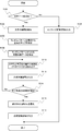
この処理を開始したCPU202は、先ず、記憶部208からコンテンツデータ2082をRAM206上に読み出し、コンテンツデータ2082が文字データを含むデータであるか否かを判断する(S100)。判断の結果、文字データがコンテンツデータ2082に含まれない場合(S100:No)、CPU202は、コンテンツデータ2082をレンダリングする。CPU202は、このレンダリングによって得られたコンテンツ画像を含むコンテンツ画像信号を、入出力I/F210からHMD100に出力する(S102)。この際、CPU202は、入出力I/F210を制御するためのプログラムをRAM206上で実行する。なお、コンテンツ画像信号を受信したHMD100において、画像提示装置114は、コンテンツ画像信号に基づくコンテンツ画像を、ハーフミラー116に向けて光学的に出射する。S102を実行後、CPU202は、この処理を終了する。
これに対し、S100の判断の結果、コンテンツデータ2082に文字データが含まれている場合(S100:Yes)、CPU202は、含まれる文字データの属性、具体的には、文字データによって示される文字を形成する線の幅を検出する(S104)。その後、CPU202は、所定の形状をしたオブジェクト(例えば、円。以下、「円」に基づき説明する。)を不規則に複数配列した微細パターン(以下、「ランダムパターン」という。)のサイズ、具体的には、オブジェクトのサイズを決定する(S106)。S106を実行後、CPU202は処理をS108に移行させる。
コンテンツデータ2082に含まれる文字データが「b」である場合を例として、S104及びS106の各処理を図5に基づき具体的に説明する。先ず、S104について説明する。S104においてCPU202は、文字「b」を形成する線の幅(ドット数)を検出する。検出する箇所については、予め定められた基準にしたがう。例えば、文字を形成する線の最大幅を検出する。また、文字を形成する線全体において、最も構成比率の高い線の幅を検出する。本実施形態では、S104でCPU202は、文字「b」を形成する「縦線50」の幅を検出する。なお、複数文字の場合、例えば、複数の文字を対象として、S104の処理を実行する。例えば、複数の文字を形成する線の中から、最大幅の線が検出される。
続けて、S106について説明する。S106においてCPU202は、S104で検出された線の幅と同一の直径を有する円(以下、「第1円」という。)を決定する。次に、CPU202は、第1円の半分の直径を有する円(以下、「第2円」という。)を決定する。そして、さらにCPU202は、第2円の半分の直径を有する円(第1円の直径に対し1/4の直径。以下、「第3円」という。)を決定する。以下、順次、直径を、例えば、半分とした円を、予め定めた数(種類)だけ、決定する。なお、第2円の直径は、第1円の直径の半分に限らず、種々所定の値とすることができる。また、第3円の直径の決定手法については、第2円と同じく、種々所定の値(例えば、1/3)とすることができる。
S108でCPU202は、S106で決定した第1円、第2円及び第3円等に基づいたランダムパターンからなる背景画像を示す背景画像データを形成する。例えば、コンテンツデータ2082に含まれる文字データが図6に示す「brother」である場合、「brother」の周囲に配置される背景画像、具体的には、図7に示される第1円~第3円その他円が不規則に配列された背景画像を示す背景画像データが形成される。ランダムパターンからなる背景画像データを形成したCPU202は、処理をS110に移行させる。
なお、S106によれば、S104で検出された線幅に応じて、第1円~第3円その他円の直径が決定される。そして、S108では、S106で決定された第1円~第3円その他の円によってランダムパターンの背景画像データが形成される。したがって、S104で検出された線幅が、異なる場合、例えば、同じ「brother」との文字であったとしても、S108で形成される背景画像は、異なるランダムパターンとなる。例えば、フォントが異なれば、ランダムパターンも異なる可能性がある。
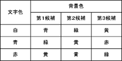
S110でCPU202は、文字色とランダムパターンを構成する第1円等の色(図4のS110において「背景色」と記載。以下、「背景色」という。)の組合せの候補を記憶部208が記憶するデータベース2084より取得する。図8は、このS110で参照されるデータベース2084を示す図である。文字色と背景色(第1候補~第3候補)が対応付けて登録されている。例えば、文字データが文字色に関する情報として「白」を含む場合、CPU202は、文字色及び背景色の組合せとして、「白及び青」を選択する。換言すれば、CPU202は、データベース2084に基づき、文字色「白」を指定し、背景色「青」を指定する。なお、文字データが、例えば、プレーンテキストで、文字色に関する情報を含まない場合、CPU202は、例えば、データベース2084の最上位のレコードに登録された文字色(図8の例においては「白」)から、順次選択する。ヘッドマウントディスプレイで文字を提示する場合、文字をなるべく明るく提示するよう白が選択される。このとき、背景は黒すなわち背景には何も提示しないので、文字の周囲からは外界像がそのまま視認されてしまう。この外界像を視認し難くするため、本実施形態ではランダムパターンからなる背景画像(背景画像データ)が形成され、その色も文字の色との組合せで決定される。
そして、CPU202は、文字データと、S108で形成したランダムパターンからなる背景画像データと、をS110で選択された文字色及び背景色に基づきレンダリングし合成画像を生成する。CPU202は、この合成画像を含む合成画像信号を、入出力I/F210からHMD100に出力する(S112)。この際、CPU202は、入出力I/F210を制御するためのプログラムをRAM206上で実行する。なお、コンテンツ画像信号を受信したHMD100において、画像提示装置114は、合成画像信号に基づく合成画像を表す画像光120a(図1参照)をハーフミラー116に向けて出射する。これにより、利用者は合成画像を視認し、認識する。なお、利用者が認識する合成画像についての詳細は、後述する。
S112を実行したCPU202は、合成画像を認識した利用者が、操作部212を介して所定の指示を入力するまで待機する。そして、利用者による指示を検出し、取得できたとき、CPU202は、取得した指示が、次の文字色及び背景色の組合せを指示するものであるか、先に実行したS110で選択した文字色及び背景色の組合せを確定(特定)する指示であるかを判断する(S114)。判断の結果、取得した指示が、次の文字色及び背景色の組合せを指示するものである場合(S114:No)、CPU202は処理をS110に戻し、再度、S110及びS112を実行する。これに対し、取得した指示が、先に実行したS110で選択した文字色及び背景色の組合せを確定する指示である場合(S114:Yes)、CPU202は処理をS116に移行する。
CPU202が、再度、S110を実行する場合について説明する。例えば、先に実行したS110において「白及び青」の組合せが選択されていた場合、CPU202は、次の組合せとしてデータベース2084に登録された「白及び緑」を選択する。ここで、背景色の「緑」は、文字色「白」との対応において第2候補である。また、先に実行したS110において文字色及び背景色の組合せとして「白及び黄」が選択されていた場合、CPU202は、次の組合せとして、文字色「白」のレコードの次のレコードに登録された文字色及び背景色の第1候補の組合せである「青及び緑」を選択する。また、先に実行したS110において文字色及び背景色の組合せとして「青及び赤」が選択されていた場合、CPU202は、次の組合せとして「赤及び黄」を選択する。さらに、先に実行したS110において「赤及び緑」の組合せが選択されていた場合、CPU202は、次の組合せとして、先頭のレコードに登録された文字色及び背景色の第1候補の組合せである「白及び青」を選択する。なお、S110の処理を実行したCPU202は、次にS112及びS114を実行するが、S112等の処理は、上記と同一の手法で実行されるため、詳細は省略する。
S116でCPU202は、確定(特定)された文字色及び背景色を、S100に先立ちRAM206上に読み出したコンテンツデータ2082に対する再生処理において採用する組合せとして選択する。S118でCPU202は、引き続き、合成画像信号をHMD100に出力する。なお、合成画像信号を受信したHMD100において、画像提示装置114は、上記同様、合成画像信号に基づく画像光120a(図1参照)をハーフミラー116に向けて出射する。これにより、利用者は合成画像を視認し、認識する。S118を実行後、CPU202は、この処理を終了する。
例えば、コンテンツデータ2082が、複数のページから構成された文書データであって、その第1ページ目に記載の文字を含む合成画像に基づき文字色及び背景色の組合せの選択が行われた場合を考える(S116)。この場合、CPU202は、第2ページ目以降についても、第2ページ目に含まれる文字の周囲に合成されるランダムパターンの背景画像データを形成する。そして、CPU202は、第2ページ目に含まれる文字データと、この背景画像データと、をS116で選択された組合せに基づき合成する。CPU202は、合成した合成データをレンダリングすることで合成画像を生成し、合成画像信号を出力する(S118)。なお、ランダムパターンからなる背景画像の形成に係る処理については、上述したS100~S108と同様の処理に基づき実行される。また、例えば、第1ページから第2ページへの移行については、利用者の操作部212を介した指示、又は予め定められた時間経過に基づき実行される。
また、制御ボックス200の電源がOFFされるまでの間、S116で選択された組合せを、RAM206上に記憶する構成とし、その間に再生処理が入力された場合は、選択済みの組合せに基づく構成とすることもできる。この場合、コンテンツデータ2082毎に組合せを選択する必要がない。
(利用者が認識する画像)
HMD100において認識される画像について、その概念を図9に基づき説明する。先ず、本実施形態を採用しないときの画像について図9(a)に基づき説明する。図9において、文字「brother」は、コンテンツデータ2082に含まれる文字データによって示される文字である。文字「brother」は、画像提示装置114から利用者の眼に視認可能に提示される。これに対し、「brother」以外の文字は、ハーフミラー116に入射し、これを透過する外光によって示される外界像を示す。なお、「brother」との文字の文字色は、説明のため「黒」としている。図9(a)において、画像提示装置114によって提示される「brother」との文字は、外界像に基づく文字と重なり合って視認される。また、「brother」との文字の周囲に外界像に基づく文字が同時に視認される。その結果、「brother」との文字が認識し難い状態になっている。
HMD100において認識される画像について、その概念を図9に基づき説明する。先ず、本実施形態を採用しないときの画像について図9(a)に基づき説明する。図9において、文字「brother」は、コンテンツデータ2082に含まれる文字データによって示される文字である。文字「brother」は、画像提示装置114から利用者の眼に視認可能に提示される。これに対し、「brother」以外の文字は、ハーフミラー116に入射し、これを透過する外光によって示される外界像を示す。なお、「brother」との文字の文字色は、説明のため「黒」としている。図9(a)において、画像提示装置114によって提示される「brother」との文字は、外界像に基づく文字と重なり合って視認される。また、「brother」との文字の周囲に外界像に基づく文字が同時に視認される。その結果、「brother」との文字が認識し難い状態になっている。
一方、図9(b)は、「brother」との文字の周囲にランダムパターンからなる背景画像を合成した合成画像を示すものである。これによれば、ランダムパターンによって、外界像の文字が文字として認識され難くなる。外界像の文字がより背景として認識され易くなるので、「brother」との文字が、図9(a)と比較し、認識し易い。
(変形例)
上記では、ランダムパターンを構成する第1円の直径が、文字を形成する線の幅に基づき決定したが(例えば、図4のS104及び図5参照)、これ以外の構成とすることもできる。例えば、文字データが、文字のサイズに関する情報(例えば、ポイント数。以下、ポイント数を例に説明する)を含むものである場合、ポイント数に対応する直径を第1円の直径として決定する構成とすることができる。この場合、記憶部208には、図10のようなテーブルが記憶され、CPU202は、図4の処理の開始を条件として、このテーブルをRAM206上に読み出す。そして、CPU202は、文字データから文字のポイント数を取得し、取得したポイント数に対応する第1円の直径を、RAM206上のテーブルにアクセスし、取得し、決定する。第2円以降の直径についても、図10同様のテーブルに登録する構成を採用することもできるが、上記の構成(例えば、第1円の直径の半分)とすることもできる。
上記では、ランダムパターンを構成する第1円の直径が、文字を形成する線の幅に基づき決定したが(例えば、図4のS104及び図5参照)、これ以外の構成とすることもできる。例えば、文字データが、文字のサイズに関する情報(例えば、ポイント数。以下、ポイント数を例に説明する)を含むものである場合、ポイント数に対応する直径を第1円の直径として決定する構成とすることができる。この場合、記憶部208には、図10のようなテーブルが記憶され、CPU202は、図4の処理の開始を条件として、このテーブルをRAM206上に読み出す。そして、CPU202は、文字データから文字のポイント数を取得し、取得したポイント数に対応する第1円の直径を、RAM206上のテーブルにアクセスし、取得し、決定する。第2円以降の直径についても、図10同様のテーブルに登録する構成を採用することもできるが、上記の構成(例えば、第1円の直径の半分)とすることもできる。
なお、文字データが、例えば、プレーンテキストである場合、文字のサイズに関する情報を含まない。このような場合は、CPU202は、予め提示するために定義し記憶したデフォルトのポイント数の文字として、処理を実行する。また、第1円の直径は、文字サイズ以下のドットサイズとすると好適である。
また、上記では、所定の形状をしたオブジェクト(上記では「○」を例として説明)を不規則に複数配列したランダムパターンを例に説明した。しかし、これ以外に、所定の形状をしたオブジェクトを、文字の周囲に規則的に複数配列した微細パターンによる背景画像とすることもできる。また、オブジェクトの色は同じ色として説明したが、ランダムパターンを形成するオブジェクトの色を複数用いて、色の配置もランダムとなるようにしてもよい。これにより、外界像の文字をより背景に同化させることができる。外界像として文字の例を示したが、外界像として表示画像に対して表示文字と同様に利用者の注意を引き易いものであっても、ランダムパターンである背景に溶け込み易く、同化され易くし、表示文字の認識を妨げ難くすることができる。
さらに、上記では、文字データによって示される文字間、例えば、「brother」を構成する「b」と「r」との間にも、ランダムパターンを構成する第1円等を合成(配置)することとした。しかし、文字データが複数の文字を含む場合、換言すれば、文字データが文字列を示すものである場合、文字列の周囲にのみ、ランダムパターン等からなる背景画像を合成する構成とすることもできる。
(実施形態の構成に基づく有利な効果)
上述したとおり、HMD100で文字データによって示される画像が提示される場合、文字をなるべく明るくするために文字色に白が選択される。すなわち、文字データで示される画像がモニタ等で表示される場合、白地に黒文字の画像が表示されるが、HMD100で提示される場合は、これが反転され、黒地に白文字の画像とされる。このとき、背景は黒、すなわち、背景には何も表示されないので、文字データで示される画像に含まれる文字の周囲から、ハーフミラー116を介して外界像がそのまま視認されてしまう。したがって、利用者の左眼118に提示された文字と重なる外界像にも文字があるような場合(図9(a)参照)、利用者は、画像提示装置114から提示された画像に含まれる文字の周囲から外界像も視認する。そして、利用者は、外界像側の文字を背景としてではなく、画像提示装置114から提示された画像に含まれる文字として視認してしまう。ここで、利用者は、画像提示装置114から提示された画像に含まれる文字と、これ以外の外界像に含まれる文字と、を識別して認識し、この認識状態が固定されないと、画像提示装置114から提示された画像に含まれる文字を識別して認識し、読解することができない。
上述したとおり、HMD100で文字データによって示される画像が提示される場合、文字をなるべく明るくするために文字色に白が選択される。すなわち、文字データで示される画像がモニタ等で表示される場合、白地に黒文字の画像が表示されるが、HMD100で提示される場合は、これが反転され、黒地に白文字の画像とされる。このとき、背景は黒、すなわち、背景には何も表示されないので、文字データで示される画像に含まれる文字の周囲から、ハーフミラー116を介して外界像がそのまま視認されてしまう。したがって、利用者の左眼118に提示された文字と重なる外界像にも文字があるような場合(図9(a)参照)、利用者は、画像提示装置114から提示された画像に含まれる文字の周囲から外界像も視認する。そして、利用者は、外界像側の文字を背景としてではなく、画像提示装置114から提示された画像に含まれる文字として視認してしまう。ここで、利用者は、画像提示装置114から提示された画像に含まれる文字と、これ以外の外界像に含まれる文字と、を識別して認識し、この認識状態が固定されないと、画像提示装置114から提示された画像に含まれる文字を識別して認識し、読解することができない。
上記実施形態のHMD100と制御ボックス200とによる構成によれば、文字データによって示される文字の周囲に、ランダムパターンからなる背景画像を合成し、合成された合成画像を含む合成画像信号を出力し(図4のS112及びS118参照)、これに基づいた合成画像を表す画像光120a(図1参照)をハーフミラー116に向けて出射することとした。これによれば、ハーフミラー116を介した外界像の視認を、背景画像によって抑制することができる。したがって、文字データによって示される文字以外を背景として認識することが可能となり、文字データによって示される文字を適切に認識し、読解することができる。
また、文字色及び背景色の組合せを、複数の組合せの中から順次選択し(図4のS110参照)、選択された組合せに基づく合成画像を認識した利用者からの入力指示にしたがい、特定の一つの組合せを確定(特定)する構成(図4のS114:Yes)を採用した。これによれば、例えば、外界像との関係において、利用者が最適と思える文字色及び背景色による合成画像を、利用者に提示することができる。
Claims (7)
- 文字データによって示される文字を含む画像を表す画像光を利用者の眼に視認可能に提示し、前記文字を含む画像を視認している利用者が外界像を表す外光を前記画像と重ねて視認可能なシースルー型のヘッドマウントディスプレイであって、
前記文字の属性を検出する検出手段と、
前記検出手段が前記文字の属性が第1属性であると検出した場合、前記文字の周囲に、前記第1属性に応じた微細パターンからなる第1背景画像の合成を決定し、前記検出手段が前記文字の属性が第2属性であると検出した場合、前記文字の周囲に、前記第2属性に応じた微細パターンからなる第2背景画像の合成を決定する決定手段と、
前記決定手段が前記第1背景画像による合成を決定した場合、前記文字の周囲に、前記第1背景画像が合成された第1合成画像を生成し、前記決定手段が前記第2背景画像による合成を決定した場合、前記文字の周囲に、前記第2背景画像が合成された第2合成画像を生成する画像生成手段と、
前記第1合成画像を表す第1画像光及び前記第2合成画像を表す第2画像光の各々を、前記利用者の眼に提示する画像提示手段と、を備えることを特徴とするヘッドマウントディスプレイ。 - 前記第1背景画像に係る微細パターンと、前記第2背景画像に係る微細パターンと、は所定の形状をしたオブジェクトを複数配列したものであって、前記オブジェクトのサイズは、前記第1属性及び前記第2属性各々に対応付けられた所定の値によって決定されることを特徴とする請求項1に記載のヘッドマウントディスプレイ。
- 前記文字の属性は、文字を形成する線の幅を含むことを特徴とする請求項1又は請求項2に記載のヘッドマウントディスプレイ。
- 前記文字の属性は、文字のサイズを含むことを特徴とする請求項1又は請求項2に記載のヘッドマウントディスプレイ。
- 前記文字に対し、複数の色の中から前記文字の文字色を指定可能で、
前記第1背景画像に対し、複数の色の中から前記第1背景画像の画像色を指定可能で、
複数の色から指定された所定の文字色と、複数の色から指定された所定の画像色と、の組合せを抽出する抽出手段を備え、
前記画像生成手段は、前記決定手段が前記第1背景画像による合成を決定した場合、前記抽出手段が抽出した組合せを構成する文字色の文字の周囲に、前記抽出手段が抽出した組合せを構成する画像色の第1背景画像を合成した第1合成画像を生成することを特徴とする請求項1に記載のヘッドマウントディスプレイ。 - 前記文字色と、前記画像色と、により構成される複数の組合せの中から、一の組合せを特定する特定手段を備え、
前記抽出手段は、前記特定手段により特定された前記一の組合せを抽出することを特徴とする請求項5に記載のヘッドマウントディスプレイ。 - 前記ヘッドマウントディスプレイが取得したコンテンツデータが文字データを含むデータであるか否かを判断する判断手段を備え、
前記検出手段は、前判断手段が前記コンテンツデータに文字データが含まれると判断した場合、前記文字の属性を検出し、
前記画像生成手段は、前記判断手段が前記コンテンツデータに文字データが含まれないと判断した場合、前記第1背景画像又は前記第2背景画像が合成されていない、前記コンテンツデータによって示されるコンテンツ画像を生成し、
前記画像提示手段は、前記コンテンツ画像を表すコンテンツ画像光を、前記利用者の眼に提示することを特徴とする請求項1に記載のヘッドマウントディスプレイ。
Applications Claiming Priority (2)
| Application Number | Priority Date | Filing Date | Title |
|---|---|---|---|
| JP2008315116A JP2010139670A (ja) | 2008-12-10 | 2008-12-10 | ヘッドマウントディスプレイ |
| JP2008-315116 | 2008-12-10 |
Publications (1)
| Publication Number | Publication Date |
|---|---|
| WO2010067557A1 true WO2010067557A1 (ja) | 2010-06-17 |
Family
ID=42242553
Family Applications (1)
| Application Number | Title | Priority Date | Filing Date |
|---|---|---|---|
| PCT/JP2009/006609 Ceased WO2010067557A1 (ja) | 2008-12-10 | 2009-12-03 | ヘッドマウントディスプレイ |
Country Status (2)
| Country | Link |
|---|---|
| JP (1) | JP2010139670A (ja) |
| WO (1) | WO2010067557A1 (ja) |
Citations (7)
| Publication number | Priority date | Publication date | Assignee | Title |
|---|---|---|---|---|
| JPH0792956A (ja) * | 1993-09-20 | 1995-04-07 | Photo Composing Mach Mfg Co Ltd | 地紋重ね文字の作成方法 |
| JPH0876740A (ja) * | 1994-08-31 | 1996-03-22 | Casio Comput Co Ltd | 文字修飾情報設定装置 |
| JP2001045261A (ja) * | 1999-07-29 | 2001-02-16 | Olympus Optical Co Ltd | 画像記録方法、画像記録装置、及び記録媒体 |
| JP2007011562A (ja) * | 2005-06-29 | 2007-01-18 | Canon Electronics Inc | 情報表示装置、方法、プログラム、及び記憶媒体 |
| JP2007193091A (ja) * | 2006-01-19 | 2007-08-02 | Taito Corp | 文字輪郭色表示方式 |
| JP2008167373A (ja) * | 2007-01-05 | 2008-07-17 | Brother Ind Ltd | 情報呈示装置 |
| JP2008271413A (ja) * | 2007-04-24 | 2008-11-06 | Olympus Corp | 画像表示装置、撮像装置、処理プログラム、画像表示装置の制御方法 |
-
2008
- 2008-12-10 JP JP2008315116A patent/JP2010139670A/ja active Pending
-
2009
- 2009-12-03 WO PCT/JP2009/006609 patent/WO2010067557A1/ja not_active Ceased
Patent Citations (7)
| Publication number | Priority date | Publication date | Assignee | Title |
|---|---|---|---|---|
| JPH0792956A (ja) * | 1993-09-20 | 1995-04-07 | Photo Composing Mach Mfg Co Ltd | 地紋重ね文字の作成方法 |
| JPH0876740A (ja) * | 1994-08-31 | 1996-03-22 | Casio Comput Co Ltd | 文字修飾情報設定装置 |
| JP2001045261A (ja) * | 1999-07-29 | 2001-02-16 | Olympus Optical Co Ltd | 画像記録方法、画像記録装置、及び記録媒体 |
| JP2007011562A (ja) * | 2005-06-29 | 2007-01-18 | Canon Electronics Inc | 情報表示装置、方法、プログラム、及び記憶媒体 |
| JP2007193091A (ja) * | 2006-01-19 | 2007-08-02 | Taito Corp | 文字輪郭色表示方式 |
| JP2008167373A (ja) * | 2007-01-05 | 2008-07-17 | Brother Ind Ltd | 情報呈示装置 |
| JP2008271413A (ja) * | 2007-04-24 | 2008-11-06 | Olympus Corp | 画像表示装置、撮像装置、処理プログラム、画像表示装置の制御方法 |
Also Published As
| Publication number | Publication date |
|---|---|
| JP2010139670A (ja) | 2010-06-24 |
Similar Documents
| Publication | Publication Date | Title |
|---|---|---|
| JP5884576B2 (ja) | 頭部装着型表示装置および頭部装着型表示装置の制御方法 | |
| US10451874B2 (en) | Image display device, method of controlling image display device, computer program, and image display system | |
| JP6008086B2 (ja) | 頭部装着型表示装置 | |
| US9870048B2 (en) | Head-mounted display device, method of controlling the same, and computer program | |
| EP4068147B1 (en) | Technique for more efficiently displaying text in virtual image generation system | |
| JP6111659B2 (ja) | 表示装置、および、表示装置の制御方法 | |
| US9348144B2 (en) | Display device and control method thereof | |
| JP2006003879A (ja) | 頭部装着型画像表示装置 | |
| TW201604586A (zh) | 顯示裝置、顯示裝置之控制方法、及程式 | |
| JP2021021889A (ja) | 表示装置および表示方法 | |
| US20180314066A1 (en) | Generating dimming masks to enhance contrast between computer-generated images and a real-world view | |
| JP6575117B2 (ja) | 表示装置、表示装置の制御方法、および、プログラム | |
| JP6428024B2 (ja) | 表示装置、表示装置の制御方法、および、プログラム | |
| JP6476673B2 (ja) | 頭部装着型表示装置、頭部装着型表示装置の制御方法、および、コンピュータープログラム | |
| JP2010139670A (ja) | ヘッドマウントディスプレイ | |
| JP6217772B2 (ja) | 頭部装着型表示装置および頭部装着型表示装置の制御方法 | |
| JP7712162B2 (ja) | 情報処理装置、情報処理方法、及び、プログラム | |
| JP7711404B2 (ja) | 表示装置、表示方法およびプログラム | |
| JP6375662B2 (ja) | 頭部装着型表示装置 | |
| JP6268704B2 (ja) | 表示装置、表示装置の制御方法、および、プログラム | |
| JP6350705B2 (ja) | 表示装置、および、表示装置の制御方法 | |
| KR20070022205A (ko) | 삼차원 표시방법, 장치 및 프로그램 | |
| JP2014127968A (ja) | 表示装置、および、表示装置の制御方法 | |
| JP2011070251A (ja) | ヘッドマウントディスプレイ | |
| NZ738277B2 (en) | Technique for more efficiently displaying text in virtual image generation system |
Legal Events
| Date | Code | Title | Description |
|---|---|---|---|
| 121 | Ep: the epo has been informed by wipo that ep was designated in this application |
Ref document number: 09831665 Country of ref document: EP Kind code of ref document: A1 |
|
| NENP | Non-entry into the national phase |
Ref country code: DE |
|
| 122 | Ep: pct application non-entry in european phase |
Ref document number: 09831665 Country of ref document: EP Kind code of ref document: A1 |