WO2010067519A1 - 映像処理装置及び映像処理方法 - Google Patents
映像処理装置及び映像処理方法 Download PDFInfo
- Publication number
- WO2010067519A1 WO2010067519A1 PCT/JP2009/006068 JP2009006068W WO2010067519A1 WO 2010067519 A1 WO2010067519 A1 WO 2010067519A1 JP 2009006068 W JP2009006068 W JP 2009006068W WO 2010067519 A1 WO2010067519 A1 WO 2010067519A1
- Authority
- WO
- WIPO (PCT)
- Prior art keywords
- phase
- image
- frame image
- coefficient
- input frame
- Prior art date
Links
Images


Classifications
-
- H—ELECTRICITY
- H04—ELECTRIC COMMUNICATION TECHNIQUE
- H04N—PICTORIAL COMMUNICATION, e.g. TELEVISION
- H04N7/00—Television systems
- H04N7/01—Conversion of standards, e.g. involving analogue television standards or digital television standards processed at pixel level
- H04N7/0135—Conversion of standards, e.g. involving analogue television standards or digital television standards processed at pixel level involving interpolation processes
- H04N7/014—Conversion of standards, e.g. involving analogue television standards or digital television standards processed at pixel level involving interpolation processes involving the use of motion vectors
-
- G—PHYSICS
- G06—COMPUTING; CALCULATING OR COUNTING
- G06T—IMAGE DATA PROCESSING OR GENERATION, IN GENERAL
- G06T1/00—General purpose image data processing
-
- H—ELECTRICITY
- H04—ELECTRIC COMMUNICATION TECHNIQUE
- H04N—PICTORIAL COMMUNICATION, e.g. TELEVISION
- H04N7/00—Television systems
- H04N7/01—Conversion of standards, e.g. involving analogue television standards or digital television standards processed at pixel level
- H04N7/0127—Conversion of standards, e.g. involving analogue television standards or digital television standards processed at pixel level by changing the field or frame frequency of the incoming video signal, e.g. frame rate converter
-
- H—ELECTRICITY
- H04—ELECTRIC COMMUNICATION TECHNIQUE
- H04N—PICTORIAL COMMUNICATION, e.g. TELEVISION
- H04N7/00—Television systems
- H04N7/01—Conversion of standards, e.g. involving analogue television standards or digital television standards processed at pixel level
- H04N7/0135—Conversion of standards, e.g. involving analogue television standards or digital television standards processed at pixel level involving interpolation processes
- H04N7/0137—Conversion of standards, e.g. involving analogue television standards or digital television standards processed at pixel level involving interpolation processes dependent on presence/absence of motion, e.g. of motion zones
Definitions
- the present invention relates to a video processing apparatus and a video processing method for performing a frame rate conversion process for converting a frame rate of a video signal, and more particularly to a video processing apparatus and a video processing method for performing a dejada process for a cinema video.
- a motion vector is obtained from frames n ⁇ 1 and n having the shortest interframe distance among combinations of two frames sandwiching an interpolation frame. If there remains a pixel that is detected and associated with a pixel of an interpolation frame and cannot be associated with a motion vector, at least one of the two frames different from the previous two frames (for example, frame n ⁇ 2 having a wider interframe distance) , N + 1) to detect the motion vector and associate it with the pixel of the interpolation frame. If there still remains a pixel that cannot be associated with the motion vector, two frames (for example, a frame different from at least one of the previous two frames).
- the image processing apparatus is disclosed to be associated with the pixels between frames.
- motion vectors can be associated with as many pixels as possible in the interpolation frame to suppress image quality deterioration of the interpolation frame.
- Patent Document 2 As an example of other frame rate conversion processing, there is a video signal system conversion device disclosed in Patent Document 2.
- a conventional video processing apparatus represented by Patent Document 2 performs frame rate conversion using a motion vector detection unit and a motion vector processing unit.
- a process for converting a so-called cinema image having an input frame frequency of 24 Hz into an image having an output frame frequency of 60 Hz by the conventional image processing apparatus will be specifically described.
- FIG. 6 is a block diagram illustrating a configuration of a conventional video processing apparatus that performs frame rate conversion
- FIG. 7 is a block diagram illustrating a configuration of a motion vector processing unit illustrated in FIG.
- the frame rate conversion process is executed using the motion vector detection unit 101 and the motion vector processing unit 102.
- the motion vector detection unit 101 detects the amount of motion between these frames using the image data of the continuous input frame n and the image data of the input frame n + 1, and moves for each pixel or each block.
- Vector V is detected.
- the motion vector processing unit 102 uses the motion vector V, the image data of the input frame n, and the image data of the input frame n + 1 to generate an image of an intermediate frame n + K (where K represents an interpolation phase coefficient, 0 ⁇ K ⁇ 1). Generate data.
- the motion vector processing unit 102 includes an interpolation phase calculation unit 103, multipliers 104 and 105, a subtractor 106, projection processing units 107 and 108, and a merge unit 109.
- the input frame image is controlled to be switched sequentially at the timing when the integer part of the addition result changes.
- the motion vector V detected by the motion vector detection unit 101 corresponds to the case where the distance between the frames is 1.0
- the image data of the intermediate frame n + K is generated by the projection processing from the image data of the input frame n.
- the image data of the intermediate frame n + K is generated by the projection processing from the image data of the input frame n + 1
- it is necessary to perform gain processing by multiplying the motion vector V by ⁇ (1 ⁇ K) K ⁇ 1.
- the sign changes because the time is projected backward from the input frame n + 1.
- the image data of the input frame n and the image data of the input frame n + 1 are each subjected to projection processing by the projection processing units 107 and 108, and each intermediate frame video is generated. These intermediate frame videos are appropriately merged by the merging unit 109, and finally the image data of the intermediate frame n + K is output.
- the sample phase on the time axis of the input frame image is 0.0, 1.0, 2.0, 3.0, if the sample phase on the time axis of the input frame image is 0.0, 1.0, 2.0, 3.0,.
- the interpolation phase which is the phase on the time axis of the output frame image, is 0.0, 0.4, 0.8, 1.2, 1.6, 2.0,.
- This phase interval is 0.4, determined by the input frame frequency / output frame frequency, and in this example 24/60.
- the motion vector processing unit 102 sets the decimal part (0.0, 0.4, 0.8, 0.2, 0.6,%) Of the interpolation phase to the motion vector V as the interpolation phase coefficient K, Each pixel data of the input frame is projected onto the interpolation phase by multiplying by the interpolation phase coefficient K, and each pixel data of the intermediate frame is generated.
- the above-described frame rate conversion processing is called so-called cinema smooth processing (cinema video dejada processing), and has the effect of converting the jerky feeling (jada) of the motion of 24 Hz video (cinema video) into smooth motion without any sense of incongruity. Yes, it is beginning to be installed in recent TV devices.
- This conventional cinema smoothing process is effective for a relatively slowly moving image and an image in which the entire screen moves in the same direction.
- the generated intermediate frame video may fail due to various causes for video in which multiple objects on the screen are moving relatively quickly in different directions. There is.
- This video failure is caused by the appearance of several motion vector detection errors such as a motion vector detection error near the boundary of an object and a motion vector detection error of an object moving at high speed. It is extremely difficult to completely eliminate the motion vector detection error, which is the cause of the above, and circuit resources are also required.
- JP 2007-288868 A Japanese Patent No. 4083265
- An object of the present invention is to provide a video processing apparatus and a video processing method capable of suppressing the video of an intermediate frame after frame rate conversion with a simple configuration.
- a video processing apparatus is a video processing apparatus that converts a frame rate of a video signal, and that detects a motion amount of an image using at least two or more input frame images that are temporally mixed.
- An amount detection unit; and an image generation unit that generates an intermediate frame image having a phase different from the phase of the input frame image using the amount of motion detected by the amount of motion detection unit.
- the intermediate frame image is generated in a phase different from the logical interpolation phase determined based on the frame frequency and the output frame frequency.
- a video processing method is a video processing method for converting a frame rate of a video signal, and detects an amount of motion of an image using at least two or more input frame images that fluctuate in time.
- the present invention it is possible to provide a video processing apparatus and a video processing method capable of suppressing the breakdown of an intermediate frame video after frame rate conversion with a simple configuration.
- FIG. 1 It is a block diagram which shows the structure of the video processing apparatus by another embodiment of this invention. It is a block diagram which shows the structure of the motion vector process part shown in FIG. It is a figure which shows the relationship between the motion vector V and the blend coefficient (beta).
- FIG. 1 is a block diagram showing a configuration of a video processing apparatus according to an embodiment of the present invention
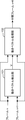
- FIG. 2 is a block diagram showing a configuration of a motion vector processing unit shown in FIG.
- the video processing apparatus includes a motion vector detection unit 1 and a motion vector processing unit 2.
- the motion vector processing unit 2 includes an interpolation phase calculation unit 21. , An interpolation phase mapping unit 22, multipliers 23 and 24, a subtracter 25, projection processing units 26 and 27, and a merge unit 28.
- the video processing device shown in FIG. 1 is used in various image display devices such as liquid crystal display devices, plasma display devices, and organic EL display devices, and video recording / playback devices such as VTRs, DVD recorders, and Blu-ray disc recorders.
- the frame rate of the signal is converted, and for example, a so-called cinema image with an input frame frequency of 24 Hz is converted into an image with an output frame frequency of 60 Hz.
- the motion vector detection unit 1 is inputted with two temporally continuous input frame images, for example, image data of an input frame n and image data of an input frame n + 1 from an external or internal predetermined circuit, and these frames A motion vector V is detected for each pixel or block.
- this motion vector detection method a known motion vector detection method is used.
- a detection method by matching processing for each block is used.
- the amount of motion of the image used in the present invention is not particularly limited to the above-described motion vector, and is the amount of motion of an image detected using at least two or more input frame images that are temporally mixed.
- Various movement amounts can be used, and the movement amount in the pan direction of the entire screen may be used.
- the motion vector processing unit 2 uses the motion vector V, the image data of the input frame n, and the image data of the input frame n + 1, and is different from the logical interpolation phase determined from the phase interval obtained by dividing the input frame frequency by the output frame frequency.
- Image data of a phase intermediate frame n + K (where K represents a logical interpolation phase coefficient and 0 ⁇ K ⁇ 1) is generated.
- the interpolation phase calculation unit 21 generates a decimal part of the interpolation phase determined from the phase interval obtained by dividing the input frame frequency by the output frame frequency as the logical interpolation phase coefficient K.
- the interpolation phase mapping unit 22 performs a mapping operation so that the interpolation phase approaches an integer phase, that is, the magnitude of the motion vector V so that the phase of the intermediate frame n + K approaches the phase of the input frame n or the input frame n + 1. Accordingly, the logical interpolation phase coefficient K generated by the interpolation phase calculation unit 21 is corrected, and the corrected interpolation phase coefficient Km is generated.
- the multiplier 23 multiplies the motion vector V and the corrected interpolation phase coefficient Km, and the projection processing unit 26 projects the image data of the input frame n by using V ⁇ Km to obtain the image data of the intermediate frame.
- the subtractor 25 subtracts 1 from the corrected interpolation phase coefficient Km, the multiplier 24 multiplies the motion vector V by (Km ⁇ 1), and the projection processing unit 27 calculates V ⁇ (Km ⁇ The image data of the frame n + 1 is projected using 1) to generate image data of the intermediate frame.
- the merge unit 28 appropriately merges the image data of these intermediate frames, and finally outputs the image data of the intermediate frame n + K.
- phase of the intermediate frame n + K serving as the output frame is a phase close to an integer
- the failure of the intermediate frame video is not easily detected by the user's eyes. This is because when the interpolation phase is a phase close to an integer, the generated video is less likely to fail despite the motion vector detection error.
- the phase of the intermediate frame is close to an integer, in other words, if the interpolation phase coefficient K (0 ⁇ K ⁇ 1) is as far as possible from 0.5, it is difficult to detect the failure of the intermediate frame video. .
- phase of the intermediate frame n + K is completely rounded to an integer phase of 0.0, 0.0, 0.0, 1.0, 1.0, 2.0,. Although it is not at all, the effect of cinema smooth will be lost. For this reason, how close the phase of the intermediate frame n + K is to an integer phase depends on (1) the magnitude of the motion amount (for example, motion vector), (2) how easily the failure of the intermediate frame image is noticeable, and (3) cinema It should be determined in consideration of factors such as how to feel judder of video (24 Hz), and (4) whether or not the entire screen is a scrolling video.
- the mapping calculation of the interpolation phase coefficient Km is performed so that the phase of the intermediate frame n + K approaches the integer phase according to the magnitude of the motion vector of the object, and the interpolation phase coefficient Km after the mapping calculation is calculated.
- An intermediate frame image is generated by multiplying the motion vector V and projecting the corresponding pixel of the input frame image using the calculated multiplication value.
- 0.4 is sequentially added starting from the initial value 0, and the addition results are 0.0, 0.4, 0.8, 1.2, 1.6, 2.0,...
- the logical interpolation phase coefficient K is 0.0, 0.4, 0.8, 0.2, 0.6, 0.0, and these five patterns are repeated.
- various synchronization signals such as a vertical synchronization signal and a horizontal synchronization signal are input to the motion vector detection unit 1 and the motion vector processing unit 2, and at the timing when the integer part of the addition result changes, The input frame image is controlled so as to be sequentially switched by the control circuit of the figure saving.
- the interpolation phase mapping unit 22 generates the post-mapping interpolation phase coefficient Km so that the logical interpolation phase coefficient K is further away from 0.5.
- Km K ⁇ ⁇ when K ⁇ 0.5
- Km 1 ⁇ (1 when K> 0.5.
- the distance from 0.5 can be varied using the value of ⁇ as a parameter.
- the conversion coefficient ⁇ is a parameter determined by the size of the motion vector of the corresponding processing pixel unit or whether the entire screen is scrolled in the same direction. For example, as the size of the motion vector increases, Small value.
- FIG. 3 is a diagram illustrating an example of interpolation phase mapping indicating the relationship between the motion vector V and the conversion coefficient ⁇ . As shown in FIG.
- the interpolation phase mapping unit 22 satisfies 0 ⁇ V
- v1 and v2 are fixed values. However, as described above, judder is more easily detected in the case of an image in which the entire screen is scrolled. It is desirable to control so that v1, or v2, or both are set to a larger value.
- ⁇ indicates the phase of the conventional output frame (intermediate frame)
- ⁇ indicates the phase of the output frame (intermediate frame) of the present embodiment
- the logical interpolation phase coefficient K of the output frame shown in the figure is equidistant with a width of 0.4, and the interpolated phase coefficient Km after mapping in this embodiment is not equidistant, but 0.25, 0. .625, 0.25, 0.625, 0.25, and the phases of the output frames are listed in order 0.0, 0.25, 0.875, 1.125, 1.75, 2.0, and so on, compared to the original logical interpolation phases 0.0, 0.4, 0.8, 1.2, 1.6, 2.0,. You can see that it is approaching. In this way, by making the interpolation phase coefficient Km close to an integer value, the time axis phase of the intermediate frame to be generated can be brought close to the time axis phase of the input frame.
- the hatching area shown in the figure is an area in which the failure of the intermediate frame video is easily detected, and the phase ⁇ of the conventional output frame (intermediate frame) is located in the hatching area.
- the phase ⁇ of all output frames (intermediate frames) is outside the hatching region, and it can be seen that in this embodiment, the failure of the intermediate frame video is difficult to detect.
- the characteristic of the ⁇ value is a straight line, but it is not particularly limited to such a linear characteristic, and as described above, it is set in advance based on a sensual investigation, and is quadratic. Complex characteristics such as a function, a function of third order or higher, an exponential function, a multivariable function, or a combination thereof may be used.
- the magnitude of the conversion coefficient ⁇ is changed according to the magnitude of the motion vector V. However, regardless of the magnitude of the motion vector V, the conversion coefficient ⁇ is set to a constant value. An interpolated phase coefficient Km after conversion may be calculated, and in this case, a corresponding effect can be obtained.
- the arithmetic expression in the interpolation phase mapping unit 22 is not particularly limited to the linear calculation as described above, and various arithmetic expressions can be used.
- FIG. 5 is a diagram schematically showing a projection process for generating image data of intermediate frame n + K from image data of input frame n or image data of input frame n + 1.
- the motion vector V detected by the motion vector detection unit 1 corresponds to the case where the distance between the frames is 1.0
- the intermediate frame is obtained by the projection processing from the image data of the input frame n.
- the projection processing unit 26 projects the image data of the input frame n using V ⁇ Km to generate intermediate frame image data
- the projection processing unit 27 uses V ⁇ (Km ⁇ 1). Is used to project the image data of the input frame n + 1 to generate intermediate frame image data.
- the merge unit 28 merges these intermediate frame image data as appropriate, and finally outputs the intermediate frame n + K image data as output frame image data at an output frame frequency of 60 Hz. Note that various known methods can be used as a method for creating the intermediate frame image by the projection processing units 26 and 27 and the merge unit 28, and thus detailed description thereof is omitted.
- the value of the conversion coefficient ⁇ described above is preferably 0.5 or more.
- the horizontal length (width) of the display screen is set to 100%, a horizontal scrolling video is used to evaluate how much of the amount of movement per second is likely to feel judder. It was also found that it becomes easier to feel judder when it is 5% / second to 15% / second, and it is easier to feel judder when it is 15% / second to 25% / second. For this reason, if most of the screen moves in the same way, when the amount of movement is 5% / second to 15% / second, the value of ⁇ is set to 0.85 or more, and 15% / second or more The value of ⁇ is preferably set to 0.75 or more at 25% / second.
- the phase of the intermediate frame is not shifted much in the case of full-screen scrolling or video close to this. Furthermore, how close the phase of the intermediate frame is to the integer phase is released to the user as the intensity of the cinema smooth effect, that is, how much the phase of the intermediate frame is set to the integer phase by the user operating a predetermined operation unit. It may be possible to select whether or not to approach.
- two temporally continuous input frame images are used.
- a motion vector is detected, a logical interpolation phase coefficient K is generated from a logical interpolation phase determined from a phase interval obtained by dividing the input frame frequency by the output frame frequency, and the generated logical interpolation phase coefficient K is the magnitude of the motion vector V.
- the phase of the intermediate frame image can be set to a phase close to an integer different from the interpolation phase, so that the failure of the intermediate frame image generated as the output frame image is less likely to be detected by the user, and the frame has a simple configuration. It is possible to prevent the video of the intermediate frame after rate conversion from failing.
- FIG. 8 is a block diagram showing the configuration of the video processing apparatus according to the second embodiment of the present invention
- FIG. 9 is a block diagram showing the configuration of the motion vector processing unit shown in FIG.
- a video processing apparatus includes a motion vector detection unit 81 and a motion vector processing unit 82, as in the embodiment of the present invention.
- the motion vector processing unit 82 includes an interpolation phase calculation unit 91, a blend coefficient calculation unit 92, multipliers 93 and 94, a subtractor 95, projection processing units 96 and 97, and a merge unit 98.
- the video processing device shown in FIG. 8 is used for various image display devices such as liquid crystal display devices, plasma display devices, organic EL display devices, video recording / reproducing devices such as VTRs, DVD recorders, Blu-ray disc recorders, etc.
- the frame rate of the signal is converted, and for example, a so-called cinema image with an input frame frequency of 24 Hz is converted into an image with an output frame frequency of 60 Hz.
- the motion vector detecting unit 81 receives two temporally continuous input frame images, for example, image data of the input frame n and image data of the input frame n + 1 from an external or internal predetermined circuit.
- a motion vector V is detected for each pixel or block.
- this motion vector detection method a known motion vector detection method is used.
- a detection method by matching processing for each block is used.
- the amount of motion of the image used in the present invention is not particularly limited to the above-described motion vector, and is the amount of motion of an image detected using at least two or more input frame images that are temporally mixed.
- Various movement amounts can be used, and the movement amount in the pan direction of the entire screen may be used.
- the motion vector processing unit 82 uses the motion vector V, the image data of the input frame n, and the image data of the input frame n + 1 to perform the logical interpolation phase determined from the phase interval obtained by dividing the input frame frequency by the output frame frequency. Image data different from the interpolation image to be originally generated is generated.
- the interpolation phase calculation unit 91 generates a decimal part of the interpolation phase determined from the phase interval obtained by dividing the input frame frequency by the output frame frequency as the logical interpolation phase coefficient K.
- the multiplier 93 multiplies the motion vector V and the logical interpolation phase coefficient K, and the projection processing unit 96 projects the image data of the input frame n using V ⁇ K to generate image data of the intermediate frame.
- the subtractor 95 subtracts 1 from the logical interpolation phase coefficient K, the multiplier 94 multiplies the motion vector V by (K ⁇ 1), and the projection processing unit 97 calculates V ⁇ (K ⁇ 1). Is used to project the image data of frame n + 1 to generate intermediate frame image data.
- the merge unit 98 appropriately merges the image data of these intermediate frames, and further blends the image data of the input frames n and n + 1 at a predetermined ratio with the image data after the merge, and finally the intermediate frame n + K. Output image data.
- the inventor of the present application indicates that the larger the blend ratio of the image data of the input frames n and n + 1, the less likely the failure of the intermediate frame video is detected by the user's eyes. It became clear from the experimental results. This is because the signal level of the broken portion of the intermediate frame video before blending is lowered by blending the image data of the input frames n and n + 1 that do not have the failure. As described above, the larger the blend ratio of the image data of the input frames n and n + 1, the more difficult it is to detect the failure of the intermediate frame video.
- the blend ratio of the image data of the input frames n and n + 1 is increased, the failure of the intermediate frame video is reduced, but the effect of cinema smoothing is also weakened. For this reason, how much the blend ratio of the image data of the input frames n and n + 1 is to be determined is (1) the magnitude of the motion amount (for example, motion vector), (2) how easily the failure of the intermediate frame video is noticeable, This should be determined in consideration of factors such as (3) how to feel judder in cinema video (24 Hz), and (4) whether or not the entire screen is a scrolling video.
- the motion amount for example, motion vector
- the larger the amount of motion for example, motion vector
- the blend ratio of the image data of the input frames n and n + 1 is controlled according to the size of the motion vector of the object, and the input frames n and n + 1 are determined from the motion vector V and the logical interpolation phase coefficient K.
- the final intermediate frame image is generated by blending the input frames n and n + 1 in accordance with the blend ratio to the video signal after merging the intermediate frames generated for the video, reducing video corruption and judder. And balance.
- 0.4 is sequentially added starting from the initial value 0, and the addition results are 0.0, 0.4, 0.8, 1.2, 1.6, 2.0,...
- the logical interpolation phase coefficient K is 0.0, 0.4, 0.8, 0.2, 0.6, 0.0, and these five patterns are repeated.
- various synchronization signals such as a vertical synchronization signal and a horizontal synchronization signal are input to the motion vector detection unit 81 and the motion vector processing unit 82, and at the timing when the integer part of the addition result changes.
- the input frame image is controlled so as to be sequentially switched by the control circuit of the figure saving.
- the blend coefficient calculation unit 92 calculates a blend coefficient ⁇ that defines the blend ratio of the input frames n and n + 1 according to the magnitude of the motion vector V.
- the blend coefficient ⁇ is a parameter determined by the size of the motion vector of the corresponding processing pixel unit or whether the entire screen is scrolled in the same direction. For example, as the size of the motion vector increases, Larger value.
- FIG. 10 is a diagram showing the relationship between the motion vector V and the blend coefficient ⁇ .
- the blend coefficient calculation unit 92 is 0 ⁇ V
- ⁇ v1 0 is set
- v1 ⁇ V ⁇ v2 ⁇ is monotonically increased from 0 to 1
- v1 and v2 are fixed values. However, as described above, judder is more easily detected in the case of an image in which the entire screen is scrolled. It is desirable to control so that v1, or v2, or both are set to a larger value.
- the blend coefficient ⁇ is determined by the magnitude of the motion vector V.
- the projection processing unit 96 uses V ⁇ K to project the image data of the input frame n and generates intermediate frame image data, and the projection processing unit 97 generates V ⁇ (K ⁇ 1).
- the intermediate frame image data generated by projecting the image data of the frame n + 1 using, the input frames n and n + 1, the blend coefficient ⁇ calculated by the blend coefficient calculation unit 92, and the logic output by the interpolation phase calculation unit 91
- An interpolation phase coefficient K is input.
- the projection processing unit 96 projects the image data of the input frame n using V ⁇ K
- the projection processing unit 97 uses the V ⁇ K.
- An intermediate frame image is temporarily generated from intermediate frame image data generated by projecting the image data of frame n + 1 using ⁇ (K ⁇ 1).
- the one closer to the interpolation phase where the intermediate frame is generated is selected from the logical interpolation phase coefficient K.
- the input frame selected here and the previously generated intermediate frame image are blended, that is, weighted averaged at a ratio defined by the blend coefficient ⁇ , and a final intermediate frame image is generated.
- the ratio defined by the blend coefficient ⁇ corresponds to the blend ratio.
- the ⁇ value characteristic is a straight line. However, it is not particularly limited to such a linear characteristic, and as described above, it is preset based on a sensual investigation, and is quadratic. Complex characteristics such as a function, a function of third order or higher, an exponential function, a multivariable function, or a combination thereof may be used.
- the blend coefficient ⁇ is changed according to the magnitude of the motion vector V. However, the blend coefficient ⁇ is set to a constant value regardless of the magnitude of the motion vector V. In this case as well, a corresponding effect can be obtained.
- two temporally continuous input frame images are used.
- a motion vector is detected, a logical interpolation phase coefficient K is generated from a logical interpolation phase determined from a phase interval obtained by dividing the input frame frequency by the output frame frequency, and the detected motion vector V and the logical interpolation phase coefficient K are used.
- the input frame image is projected and an intermediate frame image is once generated.
- the blend coefficient ⁇ is calculated from the motion vector V, and the intermediate frame image once generated and either the input frame n or n + 1
- a weighted average process based on the blend coefficient ⁇ is performed, and a final intermediate frame image is generated.
- a video processing apparatus is a video processing apparatus that converts a frame rate of a video signal, and that detects a motion amount of an image using at least two or more input frame images that fluctuate in time.
- An amount detection unit; and an image generation unit that generates an intermediate frame image having a phase different from the phase of the input frame image using the amount of motion detected by the amount of motion detection unit.
- the intermediate frame image is generated in a phase different from the logical interpolation phase determined based on the frame frequency and the output frame frequency.
- the amount of motion of the image is detected using at least two or more input frame images that are temporally changed, and the detected amount of motion is used.
- An intermediate frame image having a phase different from the phase of the input frame image is generated.
- the phase of the intermediate frame image is generated in a phase different from the logical interpolation phase determined based on the input frame frequency and the output frame frequency, the phase of the intermediate frame image is different from the logical interpolation phase.
- the phase can be close to an integer.
- the image generation unit includes a coefficient generation unit that generates a logical interpolation phase coefficient from a logical interpolation phase determined from a phase interval obtained by dividing an input frame frequency by an output frame frequency, and a logical interpolation phase coefficient generated by the coefficient generation unit A phase different from the logical interpolation phase from the input frame image using a coefficient correction unit that corrects the motion, a motion amount detected by the motion amount detection unit, and an interpolation phase coefficient corrected by the coefficient correction unit. It is preferable to provide a generation unit that generates the intermediate frame image.
- the amount of motion of the image is detected using at least two or more input frame images that are temporally changed, and from the phase interval obtained by dividing the input frame frequency by the output frame frequency.
- a logical interpolation phase coefficient is generated from the determined logical interpolation phase, the generated logical interpolation phase coefficient is corrected, and the logical interpolation phase is calculated from the input frame image using the detected motion amount and the corrected interpolation phase coefficient.
- the phase of the intermediate frame image can be made a phase close to an integer different from the logical interpolation phase, so that the failure of the intermediate frame image generated as the output frame image is prevented by the user. Therefore, it is possible to suppress the breakdown of the intermediate frame video after the frame rate conversion with a simple configuration.
- the coefficient correction unit corrects the logical interpolation phase coefficient in accordance with the motion amount detected by the motion amount detection unit so that the phase of the intermediate frame image approaches the phase of the input frame image.
- the logical interpolation phase coefficient can be corrected according to the motion amount detected by the motion amount detection unit so that the phase of the intermediate frame image approaches the phase of the input frame image.
- the phase of the frame image can be brought close to the phase of the input frame image, that is, a phase close to an integer.
- the coefficient correction unit corrects the logical interpolation phase coefficient so that the phase of the intermediate frame image approaches the phase of the input frame image as the motion amount detected by the motion amount detection unit increases. .
- the phase of the intermediate frame image can be corrected so that the phase of the intermediate frame image approaches the phase of the input frame image as the amount of motion increases, the phase of the intermediate frame image is changed as the amount of motion increases. It is possible to approach the phase of an image, that is, a phase close to an integer. As a result, even when the frame rate conversion is performed on a video with a large amount of motion, it is difficult for the user to detect the failure of the intermediate frame image generated as the output frame image, and the intermediate frame video is more likely to fail with a simple configuration. It can be surely suppressed.
- the motion amount detection unit detects a motion vector from the input frame image, and the coefficient correction unit is detected by the motion amount detection unit so that the phase of the intermediate frame image approaches the phase of the input frame image. It is preferable to correct the logical interpolation phase coefficient according to the motion vector.
- the logical interpolation phase coefficient can be corrected according to the motion vector detected by the motion amount detection unit so that the phase of the intermediate frame image approaches the phase of the input frame image.
- the phase of the frame image can be brought close to the phase of the input frame image, that is, a phase close to an integer.
- the coefficient correction unit may correct the logical interpolation phase coefficient so that the larger the magnitude of the motion vector detected by the motion amount detection unit, the closer the logical interpolation phase to the phase of the input frame image. preferable.
- the phase of the intermediate frame image can be corrected so that the phase of the intermediate frame image approaches the phase of the input frame image as the motion vector increases, the phase of the intermediate frame image becomes the input frame as the motion vector increases. It is possible to approach the phase of an image, that is, a phase close to an integer. As a result, even when a frame rate conversion is performed on a video with a large motion vector, the failure of the intermediate frame image generated as the output frame image is less likely to be detected by the user, and the video of the intermediate frame fails with a simple configuration. It can be surely suppressed.
- the video processing apparatus further includes a full-screen scroll detection unit that detects whether the video signal is full-screen scroll, and the coefficient correction unit has a phase of the intermediate frame image that is not full-screen scroll.
- the coefficient correction unit has a phase of the intermediate frame image that is not full-screen scroll. In the case of full-screen scrolling so as to approach the phase of the input frame image, it is preferable to correct the logical interpolation phase coefficient so that the phase of the intermediate frame image approaches the logical interpolation phase.
- the video signal is other than full-screen scrolling
- the failure of the intermediate frame image generated as the output frame image is less likely to be detected by the user, so the intermediate frame video after frame rate conversion can be obtained with a simple configuration.
- Another video processing apparatus is a video processing apparatus that converts a frame rate of a video signal, and that detects a motion amount of an image using at least two or more input frame images that are temporally mixed.
- An amount detection unit an image generation unit that generates an intermediate frame image having a phase different from the phase of the input frame image, using the amount of motion detected by the motion amount detection unit, the input frame image, and the intermediate frame image
- the image mixing unit determines a blend ratio between the input frame image and the intermediate frame in accordance with the motion amount detected by the motion amount detection unit.
- the amount of motion of the image is detected using at least two or more input frame images that are temporally changed, and the detected amount of motion is used.
- An intermediate frame image having a phase different from the phase of the input frame image is generated, and the input frame image and the intermediate frame image are mixed.
- the blend ratio between the input frame image and the intermediate frame is determined according to the detected amount of motion, it is possible to blend the input frames without failure at a predetermined ratio.
- the failure of the intermediate frame image generated as the output frame image is not easily detected by the user, and the video of the intermediate frame after frame rate conversion can be prevented from being broken with a simple configuration.
- a video processing method is a video processing method for converting a frame rate of a video signal, and includes a detection step of detecting a motion amount of an image using at least two input frame images that are temporally mixed. Generating an intermediate frame image having a phase different from the phase of the input frame image using the amount of motion detected in the detection step, and the image generation step includes an input frame frequency and an output frame frequency The intermediate frame image is generated at a phase different from the logical interpolation phase determined based on the above.
- the amount of motion of the image is detected using at least two or more input frame images that are temporally changed, and using the detected amount of motion, An intermediate frame image having a phase different from the phase of the input frame image is generated.
- the phase of the intermediate frame image is generated in a phase different from the logical interpolation phase determined based on the input frame frequency and the output frame frequency, the phase of the intermediate frame image is set to an integer different from the logical interpolation phase. Close phase can be achieved.
- the failure of the intermediate frame image generated as the output frame image is less likely to be detected by the user, so that it is possible to suppress the failure of the intermediate frame video after the frame rate conversion with a simple configuration.
- Another video processing method is a video processing method for converting the frame rate of a video signal, and detecting the amount of motion of an image using at least two or more input frame images that fluctuate in time.
- a step of generating an intermediate frame image having a phase different from the phase of the input frame image, using the amount of motion detected in the detection step; and mixing the input frame image and the intermediate frame image An image mixing step, wherein the image mixing step determines a blend ratio between the input frame image and the intermediate frame in accordance with the amount of motion detected in the detection step.
- the motion amount of the image is detected using at least two or more input frame images that are temporally changed, and the detected motion amount is used.
- An intermediate frame image having a phase different from the phase of the input frame image is generated, and the input frame image and the intermediate frame image are mixed.
- the blend ratio between the input frame image and the intermediate frame is determined according to the detected amount of motion, it is possible to blend the input frames without failure at a predetermined ratio.
- the failure of the intermediate frame image generated as the output frame image is not easily detected by the user, and the video of the intermediate frame after frame rate conversion can be prevented from being broken with a simple configuration.
- the video processing apparatus is useful as a video processing apparatus or the like that performs cinema video dejada processing because the video of the intermediate frame after frame rate conversion can be prevented from failing with a simple configuration.
Landscapes
- Engineering & Computer Science (AREA)
- Multimedia (AREA)
- Signal Processing (AREA)
- Physics & Mathematics (AREA)
- General Physics & Mathematics (AREA)
- Theoretical Computer Science (AREA)
- Television Systems (AREA)
Abstract
動きベクトル検出部(1)は、時間的に前後する少なくとも2つ以上の入力フレーム画像を用いて画像の動き量を検出し、補間位相算出部(21)は、入力フレーム周波数を出力フレーム周波数で除算した位相間隔から決定される論理補間位相から論理補間位相係数を生成し、補間位相マッピング部(22)は、生成された論理補間位相係数を補正し、投影処理部(26、27)及びマージ部(28)は、検出された動き量と補正された補間位相係数とを用いて、入力フレーム画像から論理補間位相とは異なる位相の中間フレーム画像を生成する。
Description
本発明は、映像信号のフレームレートを変換するフレームレート変換処理を行う映像処理装置及び映像処理方法に関し、特に、シネマ映像のデジャダ処理を行う映像処理装置及び映像処理方法に関するものである。
従来、シネマ映像のような24Hzの映像を、60Hzの映像を表示する表示装置でそのまま表示することができないため、映画フィルムなど毎秒24コマで記録された映像を、テレビジョン放送などで用いられる毎秒30フレーム(60フィールド)の映像信号に変換するフレームレート変換処理が行われる。
上記のようなフレームレート変換処理の一例として、例えば、特許文献1には、初めに、補間フレームを挟む2フレームの組み合わせのうちでフレーム間距離が最も狭いフレームn-1、nにより動きベクトルを検出して補間フレームの画素に対応付け、動きベクトルを対応付けることができない画素が残っている場合、先程の2フレームとは少なくとも一方が異なる2フレーム(例えば、フレーム間距離がより広いフレームn-2、n+1)により動きベクトルを検出して補間フレームの画素に対応付け、まだ動きベクトルを対応付けることができない画素が残っている場合、さらに先程の2フレームとは少なくとも一方が異なる2フレーム(例えば、フレーム間距離がより広いフレームn-3、n+2)により動きベクトルを検出して補間フレームの画素に対応付ける画像処理装置が開示されている。この画像処理装置では、補間フレームのできるだけ多くの画素に動きベクトルを対応付けて、補間フレームの画質劣化を抑止することができる。
また、他のフレームレート変換処理の一例として、特許文献2に開示される映像信号の方式変換装置がある。特許文献2に代表される従来の映像処理装置は、動きベクトル検出部及び動きベクトル処理部を用いてフレームレート変換を行う。以下、この従来の映像処理装置が入力フレーム周波数24Hzの所謂シネマ映像を出力フレーム周波数60Hzの映像に変換する処理について具体的に説明する。
図6は、フレームレート変換を行う従来の映像処理装置の構成を示すブロック図であり、図7は、図6に示す動きベクトル処理部の構成を示すブロック図である。
図6に示す従来の映像処理装置では、動きベクトル検出部101及び動きベクトル処理部102を用いてフレームレート変換処理が実行される。具体的には、動きベクトル検出部101は、連続する入力フレームnの画像データ及び入力フレームn+1の画像データを用いて、これらのフレーム間の動き量を検出し、画素毎に又はブロック毎に動きベクトルVを検出する。動きベクトル処理部102は、動きベクトルV、入力フレームnの画像データ及び入力フレームn+1の画像データを用いて中間フレームn+K(ここで、Kは補間位相係数を表し、0≦K<1)の画像データを生成する。
図7に示すように、動きベクトル処理部102は、補間位相算出部103、乗算器104、105、減算器106、投影処理部107、108、及びマージ部109を備える。まず、補間位相算出部103は、入力フレーム周波数/出力フレーム周波数(=24/60=0.4)を処理毎に加算し、その小数部を補間位相係数Kとして算出する。
ここでは、初期値0.0から始めて0.4を順次加算し、加算結果が0.0、0.4、0.8、1.2、1.6、2.0、…となり、小数部である補間位相係数Kは、0.0、0.4、0.8、0.2、0.6、0.0となり、この5パターンの繰り返しとなる。また、上記加算結果の整数部が変化するタイミングで、入力フレーム画像も順次切り替わるように制御される。
動きベクトル検出部101により検出された動きベクトルVは、そのフレーム間距離が1.0である場合に相当するため、入力フレームnの画像データからの投影処理によって中間フレームn+Kの画像データを生成する際には、この動きベクトルVに補間位相係数Kを乗じてゲイン処理を行う必要がある。同様に、入力フレームn+1の画像データからの投影処理によって中間フレームn+Kの画像データを生成する際には、この動きベクトルVに-(1-K)=K-1を乗じてゲイン処理を行う必要がある。なお、この場合に符号が変わるのは、入力フレームn+1から時間を遡行する方向に投影するためである。
上述したように、入力フレームnの画像データ及び入力フレームn+1の画像データを各々、投影処理部107、108にて投影処理し、各々の中間フレーム映像が生成される。これらの中間フレーム映像は、マージ部109にて適宜マージされ、最終的に中間フレームn+Kの画像データが出力される。
具体的には、フレームレートを24Hzから60Hzへ変換する場合、入力されるフレーム画像の時間軸上のサンプル位相をフレーム順に0.0、1.0、2.0、3.0、…とすると、出力されるフレーム画像の時間軸上の位相である補間位相は、0.0、0.4、0.8、1.2、1.6、2.0、…となる。この位相間隔は0.4であり、入力フレーム周波数/出力フレーム周波数で決定され、この例では、24/60である。動きベクトル処理部102は、動きベクトルVに補間位相の小数部(0.0、0.4、0.8、0.2、0.6、…)を補間位相係数Kとし、動きベクトルVに補間位相係数Kを乗じて入力フレームの各画素データを補間位相上に投影し、中間フレームの各画素データを生成する。
上記のフレームレート変換処理は、所謂シネマスムース処理(シネマ映像のデジャダ処理)と称され、24Hzの映像(シネマ映像)の動きのカクカク感(ジャダ)を違和感の無い滑らかな動きに変換する効果があり、昨今のTV装置に搭載されはじめている。この従来のシネマスムース処理は、比較的ゆっくりとした動きの映像や、画面全体が同一方向に動く映像に対して効果がある。
しかしながら、上記の従来のシネマスムース処理では、画面上の複数の物体がそれぞれ別方向に比較的早く移動している映像に対しては、種々の原因により、生成した中間フレームの映像が破綻する場合がある。この映像破綻は、物体の境界付近での動きベクトルの検出エラー、高速で移動する物体の動きベクトルの検出エラーなどいくつかの動きベクトルの検出エラーが表面化したものである。これらの原因である動きベクトルの検出エラーを完全に取り除くことは極めて難しく、またそのための回路リソースも必要とする。
本発明の目的は、簡略な構成でフレームレート変換後の中間フレームの映像が破綻することを抑制することができる映像処理装置及び映像処理方法を提供することである。
本発明の一局面に従う映像処理装置は、映像信号のフレームレートを変換する映像処理装置であって、時間的に前後する少なくとも2つ以上の入力フレーム画像を用いて画像の動き量を検出する動き量検出部と、前記動き量検出部により検出された動き量を用いて、前記入力フレーム画像の位相と異なる位相の中間フレーム画像を生成する画像生成部とを備え、前記画像生成部は、入力フレーム周波数と出力フレーム周波数とを基に決定される論理補間位相とは異なる位相に中間フレーム画像を生成する。
本発明の他の局面に従う映像処理方法は、映像信号のフレームレートを変換する映像処理方法であって、時間的に前後する少なくとも2つ以上の入力フレーム画像を用いて画像の動き量を検出する検出ステップと、前記検出ステップにおいて検出された動き量を用いて、前記入力フレーム画像の位相と異なる位相の中間フレーム画像を生成する画像生成ステップとを含み、前記画像生成ステップは、入力フレーム周波数と出力フレーム周波数とを基に決定される論理補間位相とは異なる位相に中間フレーム画像を生成する。
本発明によれば、簡略な構成でフレームレート変換後の中間フレームの映像が破綻することを抑制することができる映像処理装置及び映像処理方法を提供することができる。
(実施の形態1)
以下、本発明の一実施の形態による映像処理装置について図面を参照しながら説明する。図1は、本発明の一実施の形態による映像処理装置の構成を示すブロック図であり、図2は、図1に示す動きベクトル処理部の構成を示すブロック図である。
以下、本発明の一実施の形態による映像処理装置について図面を参照しながら説明する。図1は、本発明の一実施の形態による映像処理装置の構成を示すブロック図であり、図2は、図1に示す動きベクトル処理部の構成を示すブロック図である。
図1に示すように、本実施の形態の映像処理装置は、動きベクトル検出部1及び動きベクトル処理部2を備え、図2に示すように、動きベクトル処理部2は、補間位相算出部21、補間位相マッピング部22、乗算器23、24、減算器25、投影処理部26、27、及びマージ部28を備える。
図1に示す映像処理装置は、液晶表示装置、プラズマ表示装置、有機EL表示装置等の種々の画像表示装置、VTR、DVDレコーダ、ブルーレイディスクレコーダ等の映像記録/再生装置等に使用され、映像信号のフレームレートを変換し、例えば、入力フレーム周波数24Hzの所謂シネマ映像を出力フレーム周波数60Hzの映像に変換するシネマ映像のデジャダ処理を行う。
動きベクトル検出部1には、外部又は内部の所定の回路から、時間的に連続する2つの入力フレーム画像、例えば、入力フレームnの画像データ及び入力フレームn+1の画像データが入力され、これらのフレーム間の動き量を検出し、画素毎に又はブロック毎に動きベクトルVを検出する。この動きベクトル検出方法としては、公知の動きベクトル検出方法が用いられ、例えば、ブロック毎のマッチング処理による検出方法が用いられる。なお、本発明に用いられる画像の動き量は、上記の動きベクトルに特に限定されず、時間的に前後する少なくとも2つ以上の入力フレーム画像を用いて検出された画像の動き量であれば、種々の動き量を用いることができ、画面全体のパン方向の移動量等を用いてもよい。
動きベクトル処理部2は、動きベクトルV、入力フレームnの画像データ及び入力フレームn+1の画像データを用いて、入力フレーム周波数を出力フレーム周波数で除算した位相間隔から決定される論理補間位相とは異なる位相の中間フレームn+K(ここで、Kは論理補間位相係数を表し、0≦K<1)の画像データを生成する。
具体的には、補間位相算出部21は、入力フレーム周波数を出力フレーム周波数で除算した位相間隔から決定される補間位相の小数部を論理補間位相係数Kとして生成する。補間位相マッピング部22は、補間位相を整数位相に近づけるようにマッピング演算を行い、すなわち、中間フレームn+Kの位相が入力フレームn又は入力フレームn+1の位相に近づくように、動きベクトルVの大きさに応じて、補間位相算出部21により生成された論理補間位相係数Kを補正し、補正後の補間位相係数Kmを生成する。
乗算器23は、動きベクトルVと補正後の補間位相係数Kmとを乗算し、投影処理部26は、V×Kmを用いて入力フレームnの画像データを投影処理して中間フレームの画像データを生成する。また、減算器25は、補正後の補間位相係数Kmから1を減算し、乗算器24は、動きベクトルVと(Km-1)とを乗算し、投影処理部27は、V×(Km-1)を用いてフレームn+1の画像データを投影処理して中間フレームの画像データを生成する。マージ部28は、これらの中間フレームの画像データを適宜マージし、最終的に中間フレームn+Kの画像データを出力する。
ここで、出力フレームとなる中間フレームn+Kの位相は、整数に近い位相である場合、中間フレーム映像の破綻がユーザの目には検知されにくいことが本願発明者の実験結果により判明した。これは、補間位相が整数に近い位相である場合には、動きベクトルの検出エラーにも関わらず、生成した映像の破綻が小さくなるからである。このように、中間フレームの位相が整数に近い位相である場合、換言すれば、補間位相係数K(0≦K<1)が0.5からなるべく遠ければ、中間フレーム映像の破綻が検知されにくい。
しかしながら、中間フレームn+Kの位相を0.0、0.0、0.0、1.0、1.0、2.0、…と完全に整数位相に丸めてしまうと、中間フレーム映像の破綻は全く無いが、シネマスムースの効果もなくなってしまう。このため、中間フレームn+Kの位相をどの程度整数位相に近づけるかは、(1)動き量(例えば、動きベクトル)の大きさ、(2)中間フレーム映像の破綻の目立ちやすさ、(3)シネマ映像(24Hz)のジャダの感じ方、(4)全画面がスクロールする映像であるか否か等の要因を考慮して決定されるべきである。本願発明者の官能評価実験により、動き量(例えば、動きベクトル)の大きさが大きいほど、映像の破綻が大きくなって目立ちやすいが、ジャダ感は感じにくくなる傾向にあることが判明した。また、全画面がスクロールするような映像では、ジャダがより感知されやすくなる傾向にあることも判明した。
したがって、本実施の形態では、物体の動きベクトルの大きさに応じて、中間フレームn+Kの位相を整数位相に近づけるように補間位相係数Kmのマッピング演算を行い、マッピング演算後の補間位相係数Kmを動きベクトルVに乗じ、その算出した乗算値を用いて入力フレーム画像の該当画素を投影して中間フレーム画像を生成する。
具体的に述べると、動きベクトル処理部2において、先ず、補間位相算出部21は、補間位相算出を行い、具体的には、入力フレーム周波数/出力フレーム周波数(=24/60=0.4)を処理毎に加算し、その小数部を論理補間位相係数Kとして算出する。
ここでは、初期値0から始めて0.4を順次加算し、加算結果が0.0、0.4、0.8、1.2、1.6、2.0、…となり、小数部である論理補間位相係数Kは、0.0、0.4、0.8、0.2、0.6、0.0となり、この5パターンの繰り返しとなる。また、図示を省略しているが、垂直同期信号、水平同期信号等の各種同期信号が動きベクトル検出部1及び動きベクトル処理部2に入力され、上記加算結果の整数部が変化するタイミングで、図省の制御回路により入力フレーム画像も順次切り替わるように制御される。
次に、補間位相マッピング部22は、論理補間位相係数Kが0.5からより遠くなるように、マッピング後の補間位相係数Kmを生成する。例えば、マッピング後の補間位相係数Kmの算出方法としては、変換係数をαとすると、K≦0.5のとき、Km=K×α、K>0.5のとき、Km=1-(1-K)×α=1-α+K×αが演算される。これらの式から明らかなように、αの値をパラメータとして0.5からの距離を可変することができる。
ここで、変換係数αは、該当する処理ピクセル部の動きベクトルの大きさ、あるいは画面全体が同一方向にスクロールしているかどうかによって決定されるパラメータであり、例えば、動きベクトルの大きさが大きいほど小さい値となる。図3は、動きベクトルVと変換係数αとの関係を示す補間位相マッピング例を示す図である。図3に示すように、一例として、動きベクトルVが小さいときの所定値をv1、動きベクトルVが大きい場合の所定値をv2(>v1)とすると、補間位相マッピング部22は、0≦V<v1のとき、α=1に設定し、v1≦V≦v2のとき、αを1から0へ単調減少させ、v2<Vのとき、α=0に設定する。
なお、説明の簡略化のため、v1、v2を固定値としてあるが、前述したように全画面がスクロールする映像の場合にはよりジャダが感知されやすくなるため、全画面がスクロールする映像の場合にはv1、もしくはv2、もしくはその両方をより大きな値に設定するよう制御することが望ましい。
換言すれば、全画面がスクロールする映像の場合には同じ動きベクトルVに対してより大きな変換係数αが決定されるよう制御することが望ましい。
次に、補間位相マッピング部22は、K≦0.5のとき、マッピング後の補間位相係数Km(=K×α)を算出し、一方、K>0.5のとき、マッピング後の補間位相係数Km(=1-(1-K)×α=1-α+K×α)を算出する。
上記のように、変換係数αが動きベクトルVの大きさによって決定され、α=0.625の場合の例を図4に示す。図4は、α=0.625の場合における補間位相対比図である。前述したように、補間位相が2.0以上となる場合、繰り返しとなるため、図4では割愛している。また、視覚的な理解の助けのため、破綻が検知されやすい中間距離の補間位相(0.5付近の位相範囲)をハッチングで示している。
図4に示す○は入力フレームの位相を示し、△は従来の出力フレーム(中間フレーム)の位相を示し、□は本実施の形態の出力フレーム(中間フレーム)の位相を示し、図4の横軸には論理的な補間位相(入力フレーム周波数を出力フレーム周波数で除算した位相間隔から決定される論理補間位相)の小数部=Kの間隔を示し、縦軸には本実施の形態の補正された補間位相の小数部=Kmの間隔を示している。
図に示す出力フレームの論理的な補間位相係数Kは、0.4の幅の等間隔にあり、本実施の形態のマッピング後の補間位相係数Kmは、等間隔ではなく、0.25、0.625、0.25、0.625、0.25の間隔になっており、順に出力フレームの位相を挙げると、0.0、0.25、0.875、1.125、1.75、2.0、…となり、本来の論理的な補間位相である0.0、0.4、0.8、1.2、1.6、2.0、…と比して、何れも整数値に近づいていることがわかる。このように、補間位相係数Kmを整数値に近づけることによって、生成する中間フレームの時間軸の位相を入力フレームの時間軸の位相に近づけることができる。
また、図に示すハッチング領域は、中間フレーム映像の破綻が検知されやすい領域であり、従来の出力フレーム(中間フレーム)の位相△は、このハッチング領域内に位置しているが、本実施の形態の出力フレーム(中間フレーム)の位相□はすべてハッチング領域外にあり、本実施の形態では、中間フレーム映像の破綻が検知されにくいことがわかる。
なお、上記の説明では、α値の特性は直線としているが、このような線形特性に特に限定されず、前述したように、官能的な調査に基づいて予め設定されるものであり、2次関数、3次以上の関数、指数関数、多変数関数、これらの組み合わせ等の複雑な特性を用いてもよい。また、本実施の形態では、動きベクトルVの大きさに応じて変換係数αの大きさを変化させたが、動きベクトルVの大きさに拠らず、変換係数αを一定値に設定して変換後の補間位相係数Kmを算出してもよく、この場合も、相応の効果が得られる。さらに、補間位相マッピング部22における算術式も、上述のような線形計算に特に限定されず、種々の算術式を用いることができる。
図5は、入力フレームnの画像データ又は入力フレームn+1の画像データから中間フレームn+Kの画像データを生成する投影処理を模式的に示す図である。図5に示すように、動きベクトル検出部1で検出された動きベクトルVは、そのフレーム間距離が1.0である場合に相当するため、入力フレームnの画像データからの投影処理によって中間フレームn+Kの画像データを生成する際には、この動きベクトルVに補正後の補間位相係数Kmを乗じてゲイン処理を行う必要がある。同様に、入力フレームn+1の画像データからの投影処理によって中間フレームn+Kの画像データを生成する際には、この動きベクトルVに-(1-Km)=Km-1を乗じてゲイン処理を行う必要がある。なお、この場合に符号が変わるのは、入力フレームn+1から時間を遡行する方向に投影するためである。
上記のように、投影処理部26は、V×Kmを用いて入力フレームnの画像データを投影処理して中間フレームの画像データを生成し、投影処理部27は、V×(Km-1)を用いて入力フレームn+1の画像データを投影処理して中間フレームの画像データを生成する。マージ部28は、これらの中間フレームの画像データを適宜マージし、最終的に中間フレームn+Kの画像データを出力フレームの画像データとして出力フレーム周波数60Hzで出力する。なお、投影処理部26、27及びマージ部28による中間フレーム画像の作成方法としては、公知の種々の方法を用いることができるので、詳細な説明は省略する。
上記のように構成された映像処理装置を用いて、中間フレームの位相を中間位相(0.5)からどの程度整数位相に近づけると、シネマスムースの効果が感じられなくなるのかを評価した。画像の動きの大きさや画像の鮮明さなどの種々の要因により評価値は変化するが、中間位相(0.5)を0.25以下又は0.75以上に整数位相に近づけると、シネマスムースの効果はほとんど感じられなかった。このため、前述した変換係数αの値は0.5以上であることが好ましい。
また、表示画面の水平方向の長さ(幅)を100%としたとき、1秒間に何%の動き量が発生している場合にジャダを感じやすくなるかを、水平スクロール動画で評価したところ、5%/秒~15%/秒のときにジャダを感じやすくなり、15%/秒~25%/秒のときにややジャダ感を感じやすくなることも判った。このため、画面の大部分が同一の動きをしている場合、その動き量が5%/秒~15%/秒のときにαの値を0.85以上に設定し、15%/秒~25%/秒のときにαの値を0.75以上に設定することが好ましい。このように、全面スクロール又はこれに近い映像のときには、あまり中間フレームの位相をずらさないことが好ましい。さらに、中間フレームの位相をどの程度整数位相に近づけるかを、シネマスムースの効果の強度として、ユーザに開放する、すなわち、ユーザが所定の操作部を操作して中間フレームの位相をどの程度整数位相に近づけるかを選択できるようにしてもよい。
上記のように、本実施の形態では、入力フレーム周波数24Hzのシネマ映像を出力フレーム周波数60Hzの映像に変換するシネマ映像のデジャダ処理を行う際、時間的に連続する2つの入力フレーム画像を用いて動きベクトルが検出され、入力フレーム周波数を出力フレーム周波数で除算した位相間隔から決定される論理補間位相から論理補間位相係数Kが生成され、生成された論理補間位相係数Kが動きベクトルVの大きさに応じて決定される変換係数αを用いて補間位相係数Kmに変換され、検出された動きベクトルVと変換後の補間位相係数Kmとを用いて、入力フレーム画像を投影処理して中間フレーム画像が生成される。この結果、中間フレーム画像の位相を補間位相とは異なる整数に近い位相にすることができるので、出力フレーム画像として生成される中間フレーム画像の破綻がユーザに検知されにくくなり、簡略な構成でフレームレート変換後の中間フレームの映像が破綻することを防止することができる。
なお、上記の説明では、シネマ映像として24Hzの映像が24Hz間隔で入力される例について説明したが、放送、VTR、DVD等において、24Hzの映像は、所謂2-3プルダウンとして60Hzで入力される場合が多い。この場合であっても、入力フレーム画像をサンプルする間隔を適応的に切り替えることによって、24Hzの映像入力とみなすことができるので、本発明をそのまま適用できることは明らかである。
また、昨今の液晶TV等においては、表示周波数が60Hzではなく、120Hz、240Hzなど多種のものが登場してきているが、これらの表示周波数においても、本発明を適用できることは明らかである。
(実施の形態2)
以下、本発明の別の実施の形態による映像処理装置について図面を参照しながら説明する。図8は、本発明の第2実施の形態による映像処理装置の構成を示すブロック図であり、図9は、図8に示す動きベクトル処理部の構成を示すブロック図である。
以下、本発明の別の実施の形態による映像処理装置について図面を参照しながら説明する。図8は、本発明の第2実施の形態による映像処理装置の構成を示すブロック図であり、図9は、図8に示す動きベクトル処理部の構成を示すブロック図である。
図8に示すように、本発明の別の形態の映像処理装置は、本発明の一実施の形態と同様に、動きベクトル検出部81及び動きベクトル処理部82を備え、図9に示すように、動きベクトル処理部82は、補間位相算出部91、ブレンド係数算出部92、乗算器93、94、減算器95、投影処理部96、97、及びマージ部98を備える。
図8に示す映像処理装置は、液晶表示装置、プラズマ表示装置、有機EL表示装置等の種々の画像表示装置、VTR、DVDレコーダ、ブルーレイディスクレコーダ等の映像記録/再生装置等に使用され、映像信号のフレームレートを変換し、例えば、入力フレーム周波数24Hzの所謂シネマ映像を出力フレーム周波数60Hzの映像に変換するシネマ映像のデジャダ処理を行う。
動きベクトル検出部81には、外部又は内部の所定の回路から、時間的に連続する2つの入力フレーム画像、例えば、入力フレームnの画像データ及び入力フレームn+1の画像データが入力され、これらのフレーム間の動き量を検出し、画素毎に又はブロック毎に動きベクトルVを検出する。この動きベクトル検出方法としては、公知の動きベクトル検出方法が用いられ、例えば、ブロック毎のマッチング処理による検出方法が用いられる。なお、本発明に用いられる画像の動き量は、上記の動きベクトルに特に限定されず、時間的に前後する少なくとも2つ以上の入力フレーム画像を用いて検出された画像の動き量であれば、種々の動き量を用いることができ、画面全体のパン方向の移動量等を用いてもよい。
動きベクトル処理部82は、動きベクトルV、入力フレームnの画像データ及び入力フレームn+1の画像データを用いて、入力フレーム周波数を出力フレーム周波数で除算した位相間隔から決定される論理補間位相に対して本来生成されるべき補間画像とは異なる画像データを生成する。
具体的には、補間位相算出部91は、入力フレーム周波数を出力フレーム周波数で除算した位相間隔から決定される補間位相の小数部を論理補間位相係数Kとして生成する。乗算器93は、動きベクトルVと論理補間位相係数Kとを乗算し、投影処理部96は、V×Kを用いて入力フレームnの画像データを投影処理して中間フレームの画像データを生成する。また、減算器95は、論理補間位相係数Kから1を減算し、乗算器94は、動きベクトルVと(K-1)とを乗算し、投影処理部97は、V×(K-1)を用いてフレームn+1の画像データを投影処理して中間フレームの画像データを生成する。
マージ部98は、これらの中間フレームの画像データを適宜マージし、さらに、このマージ後の画像データに入力フレームn、n+1の画像データを所定の割合でブレンドして、最終的に中間フレームn+Kの画像データを出力する。
ここで、出力フレームとなる中間フレームn+Kの画像データに関して、入力フレームn、n+1の画像データのブレンド比率が大きいほど、中間フレーム映像の破綻がユーザの目には検知されにくいことが本願発明者の実験結果により判明した。これは、ブレンド前の中間フレーム映像が有している破綻部分の信号レベルが、破綻を有していない入力フレームn、n+1の画像データをブレンドすることで低下するためである。このように、入力フレームn、n+1の画像データのブレンド比率が大きいほど、中間フレーム映像の破綻が検知されにくくなる。
しかしながら、入力フレームn、n+1の画像データのブレンド比率を大きくしてしまうと、中間フレーム映像の破綻は低減されるが、シネマスムースの効果も弱くなってしまう。このため、入力フレームn、n+1の画像データのブレンド比率をどの程度にするかは、(1)動き量(例えば、動きベクトル)の大きさ、(2)中間フレーム映像の破綻の目立ちやすさ、(3)シネマ映像(24Hz)のジャダの感じ方、(4)全画面がスクロールする映像であるか否か等の要因を考慮して決定されるべきである。本発明の一実施の形態の説明で述べたとおり、本願発明者の官能評価実験により、動き量(例えば、動きベクトル)の大きさが大きいほど、映像の破綻が大きくなって目立ちやすいが、ジャダ感は感じにくくなる傾向にあることが判明した。また、全画面がスクロールするような映像では、ジャダがより感知されやすくなる傾向にあることも判明した。
したがって、本実施の形態では、物体の動きベクトルの大きさに応じて、入力フレームn、n+1の画像データのブレンド比率を制御し、動きベクトルVと論理補間位相係数Kとから入力フレームn、n+1に対して生成された中間フレームのマージ後の映像信号に、入力フレームn、n+1を、ブレンド比率に応じてブレンドすることにより、最終的な中間フレーム画像を生成し、映像の破綻とジャダの低減とのバランスを図る。
具体的に述べると、動きベクトル処理部82において、先ず、補間位相算出部91は、補間位相の算出を行い、具体的には、入力フレーム周波数/出力フレーム周波数(=24/60=0.4)を処理毎に加算し、その小数部を論理補間位相係数Kとして算出する。
ここでは、初期値0から始めて0.4を順次加算し、加算結果が0.0、0.4、0.8、1.2、1.6、2.0、…となり、小数部である論理補間位相係数Kは、0.0、0.4、0.8、0.2、0.6、0.0となり、この5パターンの繰り返しとなる。また、図示を省略しているが、垂直同期信号、水平同期信号等の各種同期信号が動きベクトル検出部81及び動きベクトル処理部82に入力され、上記加算結果の整数部が変化するタイミングで、図省の制御回路により入力フレーム画像も順次切り替わるように制御される。
次に、ブレンド係数算出部92は、動きベクトルVの大きさに応じて、入力フレームn、n+1のブレンド比率を規定するブレンド係数βを算出する。ブレンド係数βが大きいほど入力フレームn、n+1のブレンド比率が大きくなる。ここで、ブレンド係数βは、該当する処理ピクセル部の動きベクトルの大きさ、あるいは画面全体が同一方向にスクロールしているかどうかによって決定されるパラメータであり、例えば、動きベクトルの大きさが大きいほど大きい値となる。
図10は、動きベクトルVとブレンド係数βとの関係を示す図である。図10に示すように、一例として、動きベクトルVが小さいときの所定値をv1、動きベクトルVが大きい場合の所定値をv2(>v1)とすると、ブレンド係数算出部92は、0≦V<v1のとき、β=0に設定し、v1≦V≦v2のとき、βを0から1へ単調増加させ、v2<Vのとき、β=1に設定する。
なお、説明の簡略化のため、v1、v2を固定値としてあるが、前述したように全画面がスクロールする映像の場合にはよりジャダが感知されやすくなるため、全画面がスクロールする映像の場合にはv1、もしくはv2、もしくはその両方をより大きな値に設定するよう制御することが望ましい。
換言すれば、全画面がスクロールする映像の場合には同じ動きベクトルVに対してより小さな変換係数βが決定されるよう制御することが望ましい。上記のように、ブレンド係数βが動きベクトルVの大きさによって決定される。
次に、マージ部98の動作を説明する。マージ部98には、投影処理部96がV×Kを用いて入力フレームnの画像データを投影処理して生成する中間フレームの画像データと、投影処理部97がV×(K-1)を用いてフレームn+1の画像データを投影処理して生成する中間フレームの画像データと、入力フレームn、n+1と、ブレンド係数算出部92が算出するブレンド係数βと、補間位相算出部91が出力する論理補間位相係数Kとが入力される。
まず、本発明の一実施の形態と同様に、投影処理部96がV×Kを用いて入力フレームnの画像データを投影処理して生成する中間フレームの画像データと、投影処理部97がV×(K-1)を用いてフレームn+1の画像データを投影処理して生成する中間フレームの画像データとから、一旦中間フレーム画像が生成される。次に、入力フレームn、n+1のうち、論理補間位相係数Kから、中間フレームが生成された補間位相に近いほうが選択される。ここで選択された入力フレームと、先に一旦生成された中間フレーム画像とが、ブレンド係数βで規定される比率でブレンド、すなわち加重平均され、最終的な中間フレーム画像が生成される。ここで、上記のブレンド係数βで規定される比率が、ブレンド比率に相当する。
なお、上記の説明では、β値の特性は直線としているが、このような線形特性に特に限定されず、前述したように、官能的な調査に基づいて予め設定されるものであり、2次関数、3次以上の関数、指数関数、多変数関数、これらの組み合わせ等の複雑な特性を用いてもよい。また、本実施の形態では、動きベクトルVの大きさに応じてブレンド係数βの大きさを変化させたが、動きベクトルVの大きさに拠らず、ブレンド係数βを一定値に設定してもよく、この場合も、相応の効果が得られる。
上記のように、本実施の形態では、入力フレーム周波数24Hzのシネマ映像を出力フレーム周波数60Hzの映像に変換するシネマ映像のデジャダ処理を行う際、時間的に連続する2つの入力フレーム画像を用いて動きベクトルが検出され、入力フレーム周波数を出力フレーム周波数で除算した位相間隔から決定される論理補間位相から論理補間位相係数Kが生成され、検出された動きベクトルVと論理補間位相係数Kとを用いて、入力フレーム画像を投影処理して一旦中間フレーム画像が生成され、さらに動きベクトルVからブレンド係数βを算出し、一旦生成された中間フレーム画像と、入力フレームn、またはn+1のいずれかとの間で、ブレンド係数βに基づく加重平均処理が行われ、最終的な中間フレーム画像が生成される。この結果、破綻のない入力フレームが所定の比率ブレンドされているために、出力フレーム画像として生成される中間フレーム画像の破綻がユーザに検知されにくくなり、簡略な構成でフレームレート変換後の中間フレームの映像が破綻することを防止することができる。
なお、上記の説明では、シネマ映像として24Hzの映像が24Hz間隔で入力される例について説明したが、放送、VTR、DVD等において、24Hzの映像は、所謂2-3プルダウンとして60Hzで入力される場合が多い。この場合であっても、入力フレーム画像をサンプルする間隔を適応的に切り替えることによって、24Hzの映像入力とみなすことができるので、本発明をそのまま適用できることは明らかである。
また、昨今の液晶TV等においては、表示周波数が60Hzではなく、120Hz、240Hzなど多種のものが登場してきているが、これらの表示周波数においても、本発明を適用できることは明らかである。
上記の各実施の形態から本発明について要約すると、以下のようになる。即ち、本発明に係る映像処理装置は、映像信号のフレームレートを変換する映像処理装置であって、時間的に前後する少なくとも2つ以上の入力フレーム画像を用いて画像の動き量を検出する動き量検出部と、前記動き量検出部により検出された動き量を用いて、前記入力フレーム画像の位相と異なる位相の中間フレーム画像を生成する画像生成部とを備え、前記画像生成部は、入力フレーム周波数と出力フレーム周波数とを基に決定される論理補間位相とは異なる位相に中間フレーム画像を生成する。
この映像処理装置においては、映像信号のフレームレートを変換する際、時間的に前後する少なくとも2つ以上の入力フレーム画像を用いて画像の動き量が検出され、検出された動き量を用いて、入力フレーム画像の位相と異なる位相の中間フレーム画像が生成される。このとき、中間フレーム画像の位相が入力フレーム周波数と出力フレーム周波数とを基に決定される論理補間位相とは異なる位相に画像が生成されるので、中間フレーム画像の位相を論理補間位相とは異なる整数に近い位相にすることができる。この結果、出力フレーム画像として生成される中間フレーム画像の破綻がユーザに検知されにくくなるので、簡略な構成でフレームレート変換後の中間フレームの映像が破綻することを抑制することができる。
前記画像生成部は、入力フレーム周波数を出力フレーム周波数で除算した位相間隔から決定される論理補間位相から論理補間位相係数を生成する係数生成部と、前記係数生成部により生成された論理補間位相係数を補正する係数補正部と、前記動き量検出部により検出された動き量と、前記係数補正部により補正された補間位相係数とを用いて、前記入力フレーム画像から前記論理補間位相とは異なる位相の中間フレーム画像を生成する生成部とを備えることが好ましい。
この場合、映像信号のフレームレートを変換する際、時間的に前後する少なくとも2つ以上の入力フレーム画像を用いて画像の動き量が検出され、入力フレーム周波数を出力フレーム周波数で除算した位相間隔から決定される論理補間位相から論理補間位相係数が生成され、生成された論理補間位相係数が補正され、検出された動き量と補正された補間位相係数とを用いて入力フレーム画像から論理補間位相とは異なる位相の中間フレーム画像が生成される。このとき、論理補間位相係数を補正することにより、中間フレーム画像の位相を論理補間位相とは異なる整数に近い位相にすることができるので、出力フレーム画像として生成される中間フレーム画像の破綻がユーザに検知されにくくなり、簡略な構成でフレームレート変換後の中間フレームの映像が破綻することを抑制することができる。
前記係数補正部は、前記中間フレーム画像の位相が前記入力フレーム画像の位相に近づくように、前記動き量検出部に検出された動き量に応じて前記論理補間位相係数を補正することが好ましい。
この場合、中間フレーム画像の位相が入力フレーム画像の位相に近づくように、動き量検出部に検出された動き量に応じて論理補間位相係数を補正することができるので、動き量に応じて中間フレーム画像の位相を入力フレーム画像の位相すなわち整数に近い位相に近づけることができる。
前記係数補正部は、前記動き量検出部に検出された動き量が大きいほど、前記中間フレーム画像の位相が前記入力フレーム画像の位相に近づくように、前記論理補間位相係数を補正することが好ましい。
この場合、動き量が大きいほど、中間フレーム画像の位相が入力フレーム画像の位相に近づくように論理補間位相係数を補正することができるので、動き量が大きいほど、中間フレーム画像の位相を入力フレーム画像の位相すなわち整数に近い位相に近づけることができる。この結果、動き量が大きい映像をフレームレート変換する場合でも、出力フレーム画像として生成される中間フレーム画像の破綻がユーザにより検知されにくくなり、簡略な構成で中間フレームの映像が破綻することをより確実に抑制することができる。
前記動き量検出部は、前記入力フレーム画像から動きベクトルを検出し、前記係数補正部は、前記中間フレーム画像の位相が前記入力フレーム画像の位相に近づくように、前記動き量検出部に検出された動きベクトルに応じて前記論理補間位相係数を補正することが好ましい。
この場合、中間フレーム画像の位相が入力フレーム画像の位相に近づくように、動き量検出部に検出された動きベクトルに応じて論理補間位相係数を補正することができるので、動きベクトルに応じて中間フレーム画像の位相を入力フレーム画像の位相すなわち整数に近い位相に近づけることができる。
前記係数補正部は、前記動き量検出部に検出された動きベクトルの大きさが大きいほど、前記論理補間位相が前記入力フレーム画像の位相に近づくように、前記論理補間位相係数を補正することが好ましい。
この場合、動きベクトルが大きいほど、中間フレーム画像の位相が入力フレーム画像の位相に近づくように論理補間位相係数を補正することができるので、動きベクトルが大きいほど、中間フレーム画像の位相を入力フレーム画像の位相すなわち整数に近い位相に近づけることができる。この結果、動きベクトルが大きい映像をフレームレート変換する場合でも、出力フレーム画像として生成される中間フレーム画像の破綻がユーザにより検知されにくくなり、簡略な構成で中間フレームの映像が破綻することをより確実に抑制することができる。
上記映像処理装置は、さらに、前記映像信号が全画面スクロールか否かを検出する全画面スクロール検出部を備え、前記係数補正部は、全画面スクロールでない場合には、前記中間フレーム画像の位相が前記入力フレーム画像の位相に近づくように、全画面スクロールの場合には、前記中間フレーム画像の位相が前記論理補間位相に近づくように前記論理補間位相係数を補正することが好ましい。
この場合、映像信号が全画面スクロール以外の場合には、出力フレーム画像として生成される中間フレーム画像の破綻がユーザに検知されにくくなるので、簡略な構成でフレームレート変換後の中間フレームの映像が破綻することを抑制することができるとともに、全画面スクロールの場合には、ジャダによる違和感の無い、滑らかな映像を提供することが可能になる。
本発明に係る他の映像処理装置は、映像信号のフレームレートを変換する映像処理装置であって、時間的に前後する少なくとも2つ以上の入力フレーム画像を用いて画像の動き量を検出する動き量検出部と、前記動き量検出部により検出された動き量を用いて、前記入力フレーム画像の位相と異なる位相の中間フレーム画像を生成する画像生成部と、前記入力フレーム画像と前記中間フレーム画像とを混合する画像混合部とを備え、前記画像混合部は、前記動き量検出部により検出された動き量に応じて、前記入力フレーム画像と前記中間フレームとのブレンド比率を決定する。
この映像処理装置においては、映像信号のフレームレートを変換する際、時間的に前後する少なくとも2つ以上の入力フレーム画像を用いて画像の動き量が検出され、検出された動き量を用いて、入力フレーム画像の位相と異なる位相の中間フレーム画像が生成され、入力フレーム画像と中間フレーム画像とが混合される。このとき、検出された動き量に応じて、入力フレーム画像と中間フレームとのブレンド比率が決定されるので、破綻のない入力フレームを所定の比率でブレンドすることができる。この結果、出力フレーム画像として生成される中間フレーム画像の破綻がユーザに検知されにくくなり、簡略な構成でフレームレート変換後の中間フレームの映像が破綻することを防止することができる。
本発明に係る映像処理方法は、映像信号のフレームレートを変換する映像処理方法であって、時間的に前後する少なくとも2つ以上の入力フレーム画像を用いて画像の動き量を検出する検出ステップと、前記検出ステップにおいて検出された動き量を用いて、前記入力フレーム画像の位相と異なる位相の中間フレーム画像を生成する画像生成ステップとを含み、前記画像生成ステップは、入力フレーム周波数と出力フレーム周波数とを基に決定される論理補間位相とは異なる位相に中間フレーム画像を生成する。
この映像処理方法においては、映像信号のフレームレートを変換する際、時間的に前後する少なくとも2つ以上の入力フレーム画像を用いて画像の動き量が検出され、検出された動き量を用いて、入力フレーム画像の位相と異なる位相の中間フレーム画像が生成される。このとき、中間フレーム画像の位相が入力フレーム周波数と出力フレーム周波数とを基に決定される論理補間位相とは異なる位相に生成されるので、中間フレーム画像の位相を論理補間位相とは異なる整数に近い位相にすることができる。この結果、出力フレーム画像として生成される中間フレーム画像の破綻がユーザに検知されにくくなるので、簡略な構成でフレームレート変換後の中間フレームの映像が破綻することを抑制することができる。
本発明に係る他の映像処理方法は、映像信号のフレームレートを変換する映像処理方法であって、時間的に前後する少なくとも2つ以上の入力フレーム画像を用いて画像の動き量を検出する検出ステップと、前記検出ステップにおいて検出された動き量を用いて、前記入力フレーム画像の位相と異なる位相の中間フレーム画像を生成する画像生成ステップと、前記入力フレーム画像と前記中間フレーム画像とを混合する画像混合ステップとを含み、前記画像混合ステップは、前記検出ステップにおいて検出された動き量に応じて、前記入力フレーム画像と前記中間フレームとのブレンド比率を決定する。
この映像処理方法においては、映像信号のフレームレートを変換する際、時間的に前後する少なくとも2つ以上の入力フレーム画像を用いて画像の動き量が検出され、検出された動き量を用いて、入力フレーム画像の位相と異なる位相の中間フレーム画像が生成され、入力フレーム画像と中間フレーム画像とが混合される。このとき、検出された動き量に応じて、入力フレーム画像と中間フレームとのブレンド比率が決定されるので、破綻のない入力フレームを所定の比率でブレンドすることができる。この結果、出力フレーム画像として生成される中間フレーム画像の破綻がユーザに検知されにくくなり、簡略な構成でフレームレート変換後の中間フレームの映像が破綻することを防止することができる。
本発明に係る映像処理装置は、簡略な構成でフレームレート変換後の中間フレームの映像が破綻することを抑制することができるので、シネマ映像のデジャダ処理を行う映像処理装置等として有用である。
Claims (16)
- 映像信号のフレームレートを変換する映像処理装置であって、
時間的に前後する少なくとも2つ以上の入力フレーム画像を用いて画像の動き量を検出する動き量検出部と、
前記動き量検出部により検出された動き量を用いて、前記入力フレーム画像の位相と異なる位相の中間フレーム画像を生成する画像生成部とを備え、
前記画像生成部は、入力フレーム周波数と出力フレーム周波数とを基に決定される論理補間位相とは異なる位相に中間フレーム画像を生成することを特徴とする映像処理装置。 - 前記画像生成部は、
入力フレーム周波数を出力フレーム周波数で除算した位相間隔から決定される論理補間位相から論理補間位相係数を生成する係数生成部と、
前記係数生成部により生成された論理補間位相係数を補正する係数補正部と、
前記動き量検出部により検出された動き量と、前記係数補正部により補正された補間位相係数とを用いて、前記入力フレーム画像から前記論理補間位相とは異なる位相の中間フレーム画像を生成する生成部とを備えることを特徴とする請求項1記載の映像処理装置。 - 前記係数補正部は、前記中間フレーム画像の位相が前記入力フレーム画像の位相に近づくように、前記動き量検出部に検出された動き量に応じて前記論理補間位相係数を補正することを特徴とする請求項2記載の映像処理装置。
- 前記係数補正部は、前記動き量検出部に検出された動き量が大きいほど、前記中間フレーム画像の位相が前記入力フレーム画像の位相に近づくように、前記論理補間位相係数を補正することを特徴とする請求項3記載の映像処理装置。
- 前記動き量検出部は、前記入力フレーム画像から動きベクトルを検出し、
前記係数補正部は、前記中間フレーム画像の位相が前記入力フレーム画像の位相に近づくように、前記動き量検出部に検出された動きベクトルに応じて前記論理補間位相係数を補正することを特徴とする請求項2記載の映像処理装置。 - 前記係数補正部は、前記動き量検出部に検出された動きベクトルの大きさが大きいほど、前記論理補間位相が前記入力フレーム画像の位相に近づくように、前記論理補間位相係数を補正することを特徴とする請求項5記載の映像処理装置。
- 前記映像信号が全画面スクロールか否かを検出する全画面スクロール検出部をさらに備え、
前記係数補正部は、全画面スクロールでない場合には、前記中間フレーム画像の位相が前記入力フレーム画像の位相に近づくように、全画面スクロールの場合には、前記中間フレーム画像の位相が前記論理補間位相に近づくように前記論理補間位相係数を補正することを特徴とする請求項2、4、6のいずれかに記載の映像処理装置。 - 映像信号のフレームレートを変換する映像処理装置であって、
時間的に前後する少なくとも2つ以上の入力フレーム画像を用いて画像の動き量を検出する動き量検出部と、
前記動き量検出部により検出された動き量を用いて、前記入力フレーム画像の位相と異なる位相の中間フレーム画像を生成する画像生成部と、
前記入力フレーム画像と前記中間フレーム画像とを混合する画像混合部とを備え、
前記画像混合部は、前記動き量検出部により検出された動き量に応じて、前記入力フレーム画像と前記中間フレームとのブレンド比率を決定することを特徴とする映像処理装置。 - 映像信号のフレームレートを変換する映像処理方法であって、
時間的に前後する少なくとも2つ以上の入力フレーム画像を用いて画像の動き量を検出する検出ステップと、
前記検出ステップにおいて検出された動き量を用いて、前記入力フレーム画像の位相と異なる位相の中間フレーム画像を生成する画像生成ステップとを含み、
前記画像生成ステップは、入力フレーム周波数と出力フレーム周波数とを基に決定される論理補間位相とは異なる位相に中間フレーム画像を生成することを特徴とする映像処理方法。 - 前記画像生成ステップは、
入力フレーム周波数を出力フレーム周波数で除算した位相間隔から決定される論理補間位相から論理補間位相係数を生成する係数生成ステップと、
前記係数生成ステップにおいて生成された論理補間位相係数を補正する係数補正ステップと、
前記検出ステップにおいて検出された動き量と、前記係数補正ステップにおいて補正された補間位相係数とを用いて、前記入力フレーム画像から前記論理補間位相とは異なる位相の中間フレーム画像を生成する生成ステップとを含むことを特徴とする請求項9記載の映像処理方法。 - 前記係数補正ステップは、前記中間フレーム画像の位相が前記入力フレーム画像の位相に近づくように、前記検出ステップにおいて検出された動き量に応じて前記論理補間位相係数を補正することを特徴とする請求項10記載の映像処理方法。
- 前記係数補正ステップは、前記検出ステップにおいて検出された動き量が大きいほど、前記中間フレーム画像の位相が前記入力フレーム画像の位相に近づくように、前記論理補間位相係数を補正することを特徴とする請求項11記載の映像処理方法。
- 前記検出ステップは、前記入力フレーム画像から動きベクトルを検出し、
前記係数補正ステップは、前記中間フレーム画像の位相が前記入力フレーム画像の位相に近づくように、前記検出ステップにおいて検出された動きベクトルに応じて前記論理補間位相係数を補正することを特徴とする請求項10記載の映像処理方法。 - 前記係数補正ステップは、前記検出ステップにおいて検出された動きベクトルの大きさが大きいほど、前記論理補間位相が前記入力フレーム画像の位相に近づくように、前記論理補間位相係数を補正することを特徴とする請求項13記載の映像処理方法。
- 前記映像信号が全画面スクロールか否かを検出する全画面スクロール検出ステップをさらに含み、
前記係数補正ステップは、全画面スクロールでない場合には、前記中間フレーム画像の位相が前記入力フレーム画像の位相に近づくように、全画面スクロールの場合には、前記中間フレーム画像の位相が前記論理補間位相に近づくように前記論理補間位相係数を補正することを特徴とする請求項10、12、14のいずれかに記載の映像処理方法。 - 映像信号のフレームレートを変換する映像処理方法であって、
時間的に前後する少なくとも2つ以上の入力フレーム画像を用いて画像の動き量を検出する検出ステップと、
前記検出ステップにおいて検出された動き量を用いて、前記入力フレーム画像の位相と異なる位相の中間フレーム画像を生成する画像生成ステップと、
前記入力フレーム画像と前記中間フレーム画像とを混合する画像混合ステップとを含み、
前記画像混合ステップは、前記検出ステップにおいて検出された動き量に応じて、前記入力フレーム画像と前記中間フレームとのブレンド比率を決定することを特徴とする映像処理方法。
Applications Claiming Priority (2)
| Application Number | Priority Date | Filing Date | Title |
|---|---|---|---|
| JP2008314394 | 2008-12-10 | ||
| JP2008-314394 | 2008-12-10 |
Publications (1)
| Publication Number | Publication Date |
|---|---|
| WO2010067519A1 true WO2010067519A1 (ja) | 2010-06-17 |
Family
ID=42242517
Family Applications (1)
| Application Number | Title | Priority Date | Filing Date |
|---|---|---|---|
| PCT/JP2009/006068 WO2010067519A1 (ja) | 2008-12-10 | 2009-11-13 | 映像処理装置及び映像処理方法 |
Country Status (1)
| Country | Link |
|---|---|
| WO (1) | WO2010067519A1 (ja) |
Cited By (3)
| Publication number | Priority date | Publication date | Assignee | Title |
|---|---|---|---|---|
| JP2015177341A (ja) * | 2014-03-14 | 2015-10-05 | 株式会社東芝 | フレーム補間装置、及びフレーム補間方法 |
| WO2020039956A1 (ja) * | 2018-08-22 | 2020-02-27 | ソニー株式会社 | 表示装置、信号処理装置、及び信号処理方法 |
| WO2021006146A1 (ja) * | 2019-07-10 | 2021-01-14 | ソニー株式会社 | 画像処理装置および画像処理方法 |
Citations (5)
| Publication number | Priority date | Publication date | Assignee | Title |
|---|---|---|---|---|
| JPH0479509B2 (ja) * | 1984-11-21 | 1992-12-16 | Japan Broadcasting Corp | |
| JPH05252486A (ja) * | 1992-03-03 | 1993-09-28 | Hitachi Ltd | 映像信号の走査変換装置 |
| JP2005236937A (ja) * | 2004-01-21 | 2005-09-02 | Seiko Epson Corp | 画像処理装置、画像処理方法および画像処理プログラム |
| WO2008102826A1 (ja) * | 2007-02-20 | 2008-08-28 | Sony Corporation | 画像表示装置、映像信号処理装置および映像信号処理方法 |
| JP2009194843A (ja) * | 2008-02-18 | 2009-08-27 | Sony Corp | 映像処理装置、及び映像処理方法 |
-
2009
- 2009-11-13 WO PCT/JP2009/006068 patent/WO2010067519A1/ja active Application Filing
Patent Citations (5)
| Publication number | Priority date | Publication date | Assignee | Title |
|---|---|---|---|---|
| JPH0479509B2 (ja) * | 1984-11-21 | 1992-12-16 | Japan Broadcasting Corp | |
| JPH05252486A (ja) * | 1992-03-03 | 1993-09-28 | Hitachi Ltd | 映像信号の走査変換装置 |
| JP2005236937A (ja) * | 2004-01-21 | 2005-09-02 | Seiko Epson Corp | 画像処理装置、画像処理方法および画像処理プログラム |
| WO2008102826A1 (ja) * | 2007-02-20 | 2008-08-28 | Sony Corporation | 画像表示装置、映像信号処理装置および映像信号処理方法 |
| JP2009194843A (ja) * | 2008-02-18 | 2009-08-27 | Sony Corp | 映像処理装置、及び映像処理方法 |
Cited By (5)
| Publication number | Priority date | Publication date | Assignee | Title |
|---|---|---|---|---|
| JP2015177341A (ja) * | 2014-03-14 | 2015-10-05 | 株式会社東芝 | フレーム補間装置、及びフレーム補間方法 |
| WO2020039956A1 (ja) * | 2018-08-22 | 2020-02-27 | ソニー株式会社 | 表示装置、信号処理装置、及び信号処理方法 |
| US11930207B2 (en) | 2018-08-22 | 2024-03-12 | Saturn Licensing Llc | Display device, signal processing device, and signal processing method |
| WO2021006146A1 (ja) * | 2019-07-10 | 2021-01-14 | ソニー株式会社 | 画像処理装置および画像処理方法 |
| US11776445B2 (en) | 2019-07-10 | 2023-10-03 | Saturn Licensing Llc | Image processing device and image processing method |
Similar Documents
| Publication | Publication Date | Title |
|---|---|---|
| JP5187531B2 (ja) | 画像表示装置 | |
| US8228427B2 (en) | Image displaying device and method for preventing image quality deterioration | |
| US7965303B2 (en) | Image displaying apparatus and method, and image processing apparatus and method | |
| JP4083265B2 (ja) | 画像信号の方式変換方法および装置 | |
| EP2487900A2 (en) | Image displaying device and method, and image processing device and method | |
| JP4513913B2 (ja) | 画像信号処理装置および方法 | |
| US20090189912A1 (en) | Animation judder compensation | |
| JP2004120757A (ja) | 映像信号を処理するための方法および映像処理ユニット | |
| JP5051983B2 (ja) | フレームレート制御によるlcdぼけ低減 | |
| US20080084501A1 (en) | Image processing device | |
| JP5490236B2 (ja) | 画像処理装置および方法、画像表示装置および方法 | |
| US7239353B2 (en) | Image format conversion apparatus and method | |
| WO2010067519A1 (ja) | 映像処理装置及び映像処理方法 | |
| WO2010122726A1 (ja) | 映像処理装置及び映像処理方法 | |
| JP5015089B2 (ja) | フレームレート変換装置、フレームレート変換方法、テレビジョン受像機、フレームレート変換プログラムおよび該プログラムを記録した記録媒体 | |
| WO2008032744A1 (fr) | Dispositif de traitement vidéo et procédé de traitement vidéo | |
| JP2008028507A (ja) | 画像補正回路、画像補正方法および画像表示装置 | |
| JP2013143646A (ja) | 表示装置、フレームレート変換装置、および表示方法 | |
| JP5114274B2 (ja) | テレビジョン受信機及びそのフレームレート変換方法 | |
| JP2009135847A (ja) | 映像処理装置及びフレームレート変換方法 | |
| JP2007329952A (ja) | 画像表示装置及び方法、画像処理装置及び方法 | |
| JP4379677B2 (ja) | 画像処理装置および方法、記録媒体、プログラム、並びに表示装置 | |
| KR101577703B1 (ko) | 흐림과 이중 윤곽의 효과를 줄이는 비디오 화상 디스플레이방법과 이러한 방법을 구현하는 디바이스 | |
| JP4917867B2 (ja) | テロップ検出装置及び方法、並びに画像表示装置及び方法 | |
| JP2012182691A (ja) | 画像変換装置 |
Legal Events
| Date | Code | Title | Description |
|---|---|---|---|
| 121 | Ep: the epo has been informed by wipo that ep was designated in this application |
Ref document number: 09831627 Country of ref document: EP Kind code of ref document: A1 |
|
| NENP | Non-entry into the national phase |
Ref country code: DE |
|
| 122 | Ep: pct application non-entry in european phase |
Ref document number: 09831627 Country of ref document: EP Kind code of ref document: A1 |
|
| NENP | Non-entry into the national phase |
Ref country code: JP |