WO2010065793A1 - Exhaust flow control system and method - Google Patents
Exhaust flow control system and method Download PDFInfo
- Publication number
- WO2010065793A1 WO2010065793A1 PCT/US2009/066660 US2009066660W WO2010065793A1 WO 2010065793 A1 WO2010065793 A1 WO 2010065793A1 US 2009066660 W US2009066660 W US 2009066660W WO 2010065793 A1 WO2010065793 A1 WO 2010065793A1
- Authority
- WO
- WIPO (PCT)
- Prior art keywords
- exhaust
- temperature
- control module
- flow rate
- appliance
- Prior art date
Links
Classifications
-
- F—MECHANICAL ENGINEERING; LIGHTING; HEATING; WEAPONS; BLASTING
- F24—HEATING; RANGES; VENTILATING
- F24C—DOMESTIC STOVES OR RANGES ; DETAILS OF DOMESTIC STOVES OR RANGES, OF GENERAL APPLICATION
- F24C15/00—Details
- F24C15/20—Removing cooking fumes
- F24C15/2021—Arrangement or mounting of control or safety systems
-
- F—MECHANICAL ENGINEERING; LIGHTING; HEATING; WEAPONS; BLASTING
- F24—HEATING; RANGES; VENTILATING
- F24C—DOMESTIC STOVES OR RANGES ; DETAILS OF DOMESTIC STOVES OR RANGES, OF GENERAL APPLICATION
- F24C15/00—Details
- F24C15/20—Removing cooking fumes
- F24C15/2042—Devices for removing cooking fumes structurally associated with a cooking range e.g. downdraft
-
- F—MECHANICAL ENGINEERING; LIGHTING; HEATING; WEAPONS; BLASTING
- F24—HEATING; RANGES; VENTILATING
- F24F—AIR-CONDITIONING; AIR-HUMIDIFICATION; VENTILATION; USE OF AIR CURRENTS FOR SCREENING
- F24F11/00—Control or safety arrangements
- F24F11/30—Control or safety arrangements for purposes related to the operation of the system, e.g. for safety or monitoring
- F24F11/32—Responding to malfunctions or emergencies
- F24F11/33—Responding to malfunctions or emergencies to fire, excessive heat or smoke
-
- F—MECHANICAL ENGINEERING; LIGHTING; HEATING; WEAPONS; BLASTING
- F24—HEATING; RANGES; VENTILATING
- F24F—AIR-CONDITIONING; AIR-HUMIDIFICATION; VENTILATION; USE OF AIR CURRENTS FOR SCREENING
- F24F11/00—Control or safety arrangements
- F24F11/30—Control or safety arrangements for purposes related to the operation of the system, e.g. for safety or monitoring
- F24F11/32—Responding to malfunctions or emergencies
- F24F11/38—Failure diagnosis
-
- F—MECHANICAL ENGINEERING; LIGHTING; HEATING; WEAPONS; BLASTING
- F24—HEATING; RANGES; VENTILATING
- F24F—AIR-CONDITIONING; AIR-HUMIDIFICATION; VENTILATION; USE OF AIR CURRENTS FOR SCREENING
- F24F11/00—Control or safety arrangements
- F24F11/30—Control or safety arrangements for purposes related to the operation of the system, e.g. for safety or monitoring
- F24F11/49—Control or safety arrangements for purposes related to the operation of the system, e.g. for safety or monitoring ensuring correct operation, e.g. by trial operation or configuration checks
-
- F—MECHANICAL ENGINEERING; LIGHTING; HEATING; WEAPONS; BLASTING
- F24—HEATING; RANGES; VENTILATING
- F24F—AIR-CONDITIONING; AIR-HUMIDIFICATION; VENTILATION; USE OF AIR CURRENTS FOR SCREENING
- F24F11/00—Control or safety arrangements
- F24F11/50—Control or safety arrangements characterised by user interfaces or communication
- F24F11/52—Indication arrangements, e.g. displays
- F24F11/526—Indication arrangements, e.g. displays giving audible indications
-
- F—MECHANICAL ENGINEERING; LIGHTING; HEATING; WEAPONS; BLASTING
- F24—HEATING; RANGES; VENTILATING
- F24F—AIR-CONDITIONING; AIR-HUMIDIFICATION; VENTILATION; USE OF AIR CURRENTS FOR SCREENING
- F24F11/00—Control or safety arrangements
- F24F11/62—Control or safety arrangements characterised by the type of control or by internal processing, e.g. using fuzzy logic, adaptive control or estimation of values
- F24F11/63—Electronic processing
- F24F11/64—Electronic processing using pre-stored data
-
- F—MECHANICAL ENGINEERING; LIGHTING; HEATING; WEAPONS; BLASTING
- F24—HEATING; RANGES; VENTILATING
- F24F—AIR-CONDITIONING; AIR-HUMIDIFICATION; VENTILATION; USE OF AIR CURRENTS FOR SCREENING
- F24F11/00—Control or safety arrangements
- F24F11/70—Control systems characterised by their outputs; Constructional details thereof
- F24F11/72—Control systems characterised by their outputs; Constructional details thereof for controlling the supply of treated air, e.g. its pressure
- F24F11/74—Control systems characterised by their outputs; Constructional details thereof for controlling the supply of treated air, e.g. its pressure for controlling air flow rate or air velocity
- F24F11/76—Control systems characterised by their outputs; Constructional details thereof for controlling the supply of treated air, e.g. its pressure for controlling air flow rate or air velocity by means responsive to temperature, e.g. bimetal springs
-
- F—MECHANICAL ENGINEERING; LIGHTING; HEATING; WEAPONS; BLASTING
- F24—HEATING; RANGES; VENTILATING
- F24F—AIR-CONDITIONING; AIR-HUMIDIFICATION; VENTILATION; USE OF AIR CURRENTS FOR SCREENING
- F24F11/00—Control or safety arrangements
- F24F11/70—Control systems characterised by their outputs; Constructional details thereof
- F24F11/72—Control systems characterised by their outputs; Constructional details thereof for controlling the supply of treated air, e.g. its pressure
- F24F11/74—Control systems characterised by their outputs; Constructional details thereof for controlling the supply of treated air, e.g. its pressure for controlling air flow rate or air velocity
- F24F11/77—Control systems characterised by their outputs; Constructional details thereof for controlling the supply of treated air, e.g. its pressure for controlling air flow rate or air velocity by controlling the speed of ventilators
-
- F—MECHANICAL ENGINEERING; LIGHTING; HEATING; WEAPONS; BLASTING
- F24—HEATING; RANGES; VENTILATING
- F24F—AIR-CONDITIONING; AIR-HUMIDIFICATION; VENTILATION; USE OF AIR CURRENTS FOR SCREENING
- F24F7/00—Ventilation
- F24F7/04—Ventilation with ducting systems, e.g. by double walls; with natural circulation
- F24F7/06—Ventilation with ducting systems, e.g. by double walls; with natural circulation with forced air circulation, e.g. by fan positioning of a ventilator in or against a conduit
-
- F—MECHANICAL ENGINEERING; LIGHTING; HEATING; WEAPONS; BLASTING
- F24—HEATING; RANGES; VENTILATING
- F24F—AIR-CONDITIONING; AIR-HUMIDIFICATION; VENTILATION; USE OF AIR CURRENTS FOR SCREENING
- F24F11/00—Control or safety arrangements
- F24F11/30—Control or safety arrangements for purposes related to the operation of the system, e.g. for safety or monitoring
-
- F—MECHANICAL ENGINEERING; LIGHTING; HEATING; WEAPONS; BLASTING
- F24—HEATING; RANGES; VENTILATING
- F24F—AIR-CONDITIONING; AIR-HUMIDIFICATION; VENTILATION; USE OF AIR CURRENTS FOR SCREENING
- F24F11/00—Control or safety arrangements
- F24F11/50—Control or safety arrangements characterised by user interfaces or communication
- F24F11/56—Remote control
-
- F—MECHANICAL ENGINEERING; LIGHTING; HEATING; WEAPONS; BLASTING
- F24—HEATING; RANGES; VENTILATING
- F24F—AIR-CONDITIONING; AIR-HUMIDIFICATION; VENTILATION; USE OF AIR CURRENTS FOR SCREENING
- F24F2110/00—Control inputs relating to air properties
- F24F2110/10—Temperature
-
- F—MECHANICAL ENGINEERING; LIGHTING; HEATING; WEAPONS; BLASTING
- F24—HEATING; RANGES; VENTILATING
- F24F—AIR-CONDITIONING; AIR-HUMIDIFICATION; VENTILATION; USE OF AIR CURRENTS FOR SCREENING
- F24F2110/00—Control inputs relating to air properties
- F24F2110/10—Temperature
- F24F2110/12—Temperature of the outside air
-
- F—MECHANICAL ENGINEERING; LIGHTING; HEATING; WEAPONS; BLASTING
- F24—HEATING; RANGES; VENTILATING
- F24F—AIR-CONDITIONING; AIR-HUMIDIFICATION; VENTILATION; USE OF AIR CURRENTS FOR SCREENING
- F24F2110/00—Control inputs relating to air properties
- F24F2110/40—Pressure, e.g. wind pressure
-
- Y—GENERAL TAGGING OF NEW TECHNOLOGICAL DEVELOPMENTS; GENERAL TAGGING OF CROSS-SECTIONAL TECHNOLOGIES SPANNING OVER SEVERAL SECTIONS OF THE IPC; TECHNICAL SUBJECTS COVERED BY FORMER USPC CROSS-REFERENCE ART COLLECTIONS [XRACs] AND DIGESTS
- Y02—TECHNOLOGIES OR APPLICATIONS FOR MITIGATION OR ADAPTATION AGAINST CLIMATE CHANGE
- Y02B—CLIMATE CHANGE MITIGATION TECHNOLOGIES RELATED TO BUILDINGS, e.g. HOUSING, HOUSE APPLIANCES OR RELATED END-USER APPLICATIONS
- Y02B30/00—Energy efficient heating, ventilation or air conditioning [HVAC]
- Y02B30/70—Efficient control or regulation technologies, e.g. for control of refrigerant flow, motor or heating
-
- Y—GENERAL TAGGING OF NEW TECHNOLOGICAL DEVELOPMENTS; GENERAL TAGGING OF CROSS-SECTIONAL TECHNOLOGIES SPANNING OVER SEVERAL SECTIONS OF THE IPC; TECHNICAL SUBJECTS COVERED BY FORMER USPC CROSS-REFERENCE ART COLLECTIONS [XRACs] AND DIGESTS
- Y10—TECHNICAL SUBJECTS COVERED BY FORMER USPC
- Y10T—TECHNICAL SUBJECTS COVERED BY FORMER US CLASSIFICATION
- Y10T137/00—Fluid handling
- Y10T137/0318—Processes
- Y10T137/0324—With control of flow by a condition or characteristic of a fluid
Definitions
- Embodiments of the present invention relate generally to controlling exhaust air flow in a ventilation system. More specifically, embodiments relate to controlling the exhaust air flow rate in an exhaust air ventilation system based on the status of a cooking appliance.
- Exhaust ventilation systems can be used to remove fumes and air contaminants generated by cooking appliances. These systems are usually equipped with an exhaust hood positioned above the cooking appliance, the hood including an exhaust fan that removes fumes from the area where the cooking appliance is used. Some systems also include manual or automatic dampers that can be opened or closed to change the exhaust air flow in the system.
- One or more embodiments include a method for controlling the exhaust flow rate in an exhaust ventilation system including an exhaust hood positioned above a cooking appliance.
- the method can include measuring a temperature of the exhaust air in the vicinity of the exhaust hood, measuring a radiant temperature of the exhaust air in the vicinity of the cooking appliance, determining an appliance status based on the measured exhaust air temperature and radiant temperature, and controlling the exhaust flow rate in response to the determined appliance status.
- One or more embodiments can include controlling the exhaust air flow rate in an exhaust ventilation system where the exhaust air temperature near the vicinity of the exhaust hood is measured using a temperature sensor.
- Embodiments can further comprise controlling the exhaust air flow rate in an exhaust ventilation system where the radiant temperature in the vicinity of the cooking appliance is measured using an infrared (IR) sensor.
- IR infrared
- Embodiments can further comprise controlling the exhaust air flow rate in an exhaust ventilation system where the appliance status includes a cooking state, an idle state and an off state. In a cooking state it can be determined that there is a fluctuation in the radiant temperature and the mean radiant temperature of the cooking appliance, or that the exhaust temperature is above a minimum exhaust temperature.
- an idle state it can be determined that there is no radiant temperature fluctuation for the duration of the cooking time and the exhaust temperature is less than a predetermined minimum exhaust temperature.
- the mean radiant temperature is less than a predetermined minimum radiant temperature and that the exhaust temperature is less than a predetermined ambient air temperature plus the mean ambient air temperature of the space in the vicinity of the cooking appliance.
- Embodiments can further comprise controlling the exhaust air flow rate in an exhaust ventilation system positioned above a cooking appliance where the exhaust air flow is controlled by turning the fan on or off, or by changing the fan speed and the damper position based on the determined appliance status.
- Embodiments can further comprise controlling the exhaust air flow rate in an exhaust ventilation system positioned above a cooking appliance where the exhaust flow rate is changed based on a change in the appliance status.
- Embodiments can further comprise controlling the exhaust air flow rate in an exhaust ventilation system positioned above a cooking appliance where the exhaust flow rate is changed between a predetermined design exhaust air flow rate, a predetermined idle exhaust air flow rate, and an off exhaust air flow rate, in response to the detected change in appliance status.
- Embodiments can further comprise controlling the exhaust air flow rate in an exhaust ventilation system positioned above a cooking appliance where the system is calibrated before controlling the exhaust flow rate.
- Embodiments can further comprise controlling the exhaust air flow rate in an exhaust ventilation system positioned above a cooking appliance where a difference between the exhaust air temperature and a temperature of ambient space in the vicinity of the ventilation system is measured to determine appliance status.
- Embodiments can further comprise controlling the exhaust air flow rate in an exhaust ventilation system positioned above a cooking appliance where the cooking appliance is in the cooking state when there is a fluctuation in the radiant temperature and the radiant temperature is greater than a predetermined minimum radiant temperature, the cooking appliance is in the idle state when there is no fluctuation in the radiant temperature, and the cooking appliance is in the off state when there is no fluctuation in the radiant temperature and the radiant temperature is less than a minimum predetermined radiant temperature.
- Embodiments can further comprise controlling the exhaust air flow rate in an exhaust ventilation system positioned above a cooking appliance where the cooking appliance is in the cooking state when the exhaust air temperature is greater than or equal to a maximum predetermined ambient temperature, the cooking appliance is in the idle state when the exhaust air temperature is less than the predetermined maximum ambient temperature, and the cooking appliance is in the off state when the exhaust air temperature is less than a predetermined ambient temperature.
- Embodiments can further comprise measuring the radiant temperature using an infrared sensor.
- Embodiments can further comprise an exhaust ventilation system including an exhaust hood mounted above a cooking appliance with an exhaust fan for removing exhaust air generated by the cooking appliance, at least one sensor for measuring a radiant temperature of the cooking appliance, at least one temperature sensor attached to the exhaust hood for measuring the temperature of the exhaust air, and a control module to determine a status of the cooking appliance based on the measured radiant temperature and exhaust air temperature, and to control an exhaust air flow rate based on said appliance status.
- an exhaust ventilation system including an exhaust hood mounted above a cooking appliance with an exhaust fan for removing exhaust air generated by the cooking appliance, at least one sensor for measuring a radiant temperature of the cooking appliance, at least one temperature sensor attached to the exhaust hood for measuring the temperature of the exhaust air, and a control module to determine a status of the cooking appliance based on the measured radiant temperature and exhaust air temperature, and to control an exhaust air flow rate based on said appliance status.
- Embodiments can further comprise an infrared sensor for measuring the radiant temperature, a temperature sensor for measuring the exhaust air temperature in the vicinity of the exhaust hood, and a control module which can include a processor to determine the status of the cooking appliance, and to control the exhaust flow rate based on the appliance status.
- Embodiments can further comprise a control module that controls the exhaust air flow rate by controlling a speed of an exhaust fan at least one motorized balancing damper attached to the exhaust hood to control a volume of the exhaust air that enters a hood duct.
- control module can further control the exhaust air flow rate by controlling a position of the at least one motorized balancing damper.
- control module can determine the appliance status where the appliance status includes a cooking state, an idle state and an off state.
- Embodiments can further comprise a control module that controls the exhaust flow rate by changing the exhaust flow rate between a design exhaust flow rate (Qdesign), an idle exhaust flow rate (Qidle), and an off exhaust flow rate (0), based on a change in the appliance status.
- Qdesign design exhaust flow rate
- Qidle idle exhaust flow rate
- (0) off exhaust flow rate
- Embodiments can further comprise a control module that changes the exhaust flow rate to design exhaust flow rate (Qdesign) when the appliance is determined to be in the cooking state, to idle exhaust flow rate (Qidle) when the appliance status is determined to be in the idle state, and to the off exhaust flow rate when the appliance is determined to be in the off state.
- Qdesign design exhaust flow rate
- Qidle idle exhaust flow rate
- Embodiments can further comprise a control module that can further determine a fluctuation in the radiant temperature.
- Embodiments can further comprise a control module that can determine that the cooking appliance is in the cooking state when there is a fluctuation in the radiant temperature and the radiant temperature is greater than a predetermined minimum radiant temperature, the cooking appliance is in the idle state when there is no fluctuation in the radiant temperature, and the cooking appliance is in the off state when there is no fluctuation in the radiant temperature and the radiant temperature is less than a minimum predetermined radiant temperature.
- Embodiments can further comprise a temperature sensor for measuring an ambient temperature of the air in the vicinity of the ventilation system, and a control module that can further determine a difference between the exhaust air temperature in the vicinity of the exhaust hood and the ambient temperature in the vicinity of the ventilation system.
- Embodiments can further comprise a control module that determines that the cooking appliance is in the cooking state when the exhaust air temperature is greater than or equal to a maximum predetermined ambient temperature, the cooking appliance is in the idle state when the exhaust air temperature is less than the predetermined maximum ambient temperature, and the cooking appliance is in the off state when the exhaust air temperature is less than a predetermined ambient temperature.
- Embodiments can further comprise a control module that controls the exhaust flow rate after the system is calibrated.
- Embodiments can comprise a control module for controlling an exhaust flow rate in an exhaust ventilating system comprising an exhaust hood positioned above a cooking appliance, the control module comprising a processor for determining a status of the cooking appliance, and for controlling the exhaust flow rate based on the appliance status.
- control module can further comprise controlling an exhaust flow rate where the appliance status includes one of a cooking state, an idle state and an off state.
- the control module can further comprise controlling an exhaust flow rate where the exhaust flow rate includes one of a design exhaust flow rate (Qdesign), an idle exhaust flow rate (Qidle), and an off exhaust flow rate.
- the control module can further comprise a function to change the exhaust flow rate from the design exhaust flow rate to the idle exhaust flow rate and to the off exhaust flow rate.
- the control module can further comprise controlling an exhaust flow rate where in the cooking state the control module changes the exhaust flow rate to the design air flow rate, in the idle cooking state the control module changes the exhaust flow rate to the idle exhaust flow rate and in the off state the control module changes the exhaust flow to the off exhaust flow rate.
- control module can further comprise controlling an exhaust flow rate where the processor determines the appliance status by measuring an ambient temperature of the exhaust air generated by the cooking appliance, and by measuring a radiant temperature of the cooking appliance.
- the control module can further comprise controlling an exhaust flow rate where the processor determines a cooking state when the exhaust air temperature is greater than or equal to a predetermined maximum ambient temperature, an idle state when the exhaust air temperature is less than the predetermined maximum ambient temperature, and an off state when the exhaust air temperature is less than a predetermined ambient temperature.
- the control module can further comprise controlling the exhaust flow rate where the processor determines a cooking state when there is a fluctuation in the radiant temperature and the radiant temperature is greater than a predetermined minimum radiant temperature, an idle state when there is no fluctuation in the radiant temperature, and an off state when there is no fluctuation in the radiant temperature and the radiant temperature is less than a predetermined minimum radiant temperature.
- the control module can further comprise controlling an exhaust flow rate by controlling a speed of an exhaust fan attached to the exhaust hood for removing the exhaust air generated by the cooking appliance, controlling an exhaust flow rate by controlling a position of at least one balancing damper attached to the exhaust hood, and controlling an exhaust flow rate where the control module further calibrates the system before the controller controls the exhaust flow rate.
- FIG. 1 is a perspective view diagrammatically illustrating an exhaust ventilating system positioned above a cooking appliance and having an exhaust airflow control system according to various embodiments;
- FIG. 2 is a perspective view diagrammatically illustrating an exhaust ventilating system having motorized dampers
- FIG. 3 is a block diagram of an exemplary exhaust air flow rate control system in accordance with the disclosure.
- FIG. 4 is a flow chart illustrating an exemplary exhaust flow rate control method according to various embodiments
- FIG. 5 is a flow diagram of an exemplary start-up routine of at least one embodiment with or without automatic dampers
- FIG. 6 is a flow diagram of a check routine of at least one embodiment with a single hood and no dampers
- FIG. 7 is a flow diagram of a checking routine of at least one embodiment with multiple hoods, one fan and motorized dampers;
- FIG. 8 is a flow diagram of a calibration routine for at least one embodiment with a single hood, single fan and no motorized dampers;
- FIG. 9 is a flow diagram of a calibration routine for at least one embodiment with multiple hoods, one fan and no motorized dampers;
- FIG. 10 is a flow diagram of a calibration routine for at least one embodiment with one or multiple hoods, one fan, and motorized dampers;
- FIG. 11 is a flow diagram of an operation routine for at least one embodiment without motorized balancing dampers
- FIG. 12 is a flow diagram of an operation routine for at least one embodiment with motorized balancing dampers
- FIG. 13 is a block diagram of an exemplary exhaust flow control system in accordance with the present disclosure.
- FIG. 14 is a block diagram of an exemplary exhaust flow control system in accordance with the present disclosure.
- FIG. 15 is a block diagram of an exemplary exhaust flow control system in accordance with the present disclosure.
- an exemplary exhaust ventilation system 100 including an exhaust hood 105 positioned above a plurality of cooking appliances 115 and provided in communication with an exhaust assembly 145 through an exhaust duct 1 10.
- a bottom opening of the exhaust hood 105 may be generally rectangular but can have any other desired shape. Walls of the hood 105 define an interior volume 185, which communicates with a downwardly facing bottom opening 190 at an end of the hood 105 that is positioned over the cooking appliances 115.
- the interior volume 185 can also communicate with the exhaust assembly 145 through the exhaust duct 110.
- the exhaust duct 110 can extend upwardly toward the outside venting environment through the exhaust assembly 145.
- Exhaust assembly 145 can include a motorized exhaust fan 130, by which the exhaust air generated by the cooking appliances 115 is drawn into the exhaust duct 110 and for expelling into the outside venting environment.
- a motorized exhaust fan 130 by which the exhaust air generated by the cooking appliances 115 is drawn into the exhaust duct 110 and for expelling into the outside venting environment.
- an exhaust air flow path 165 is established between the cooking appliances 115 and the outside venting environment.
- fumes, air pollutants and other air particles are exhausted into the outside venting environment through the exhaust duct 110 and exhaust assembly 145.
- the exhaust ventilating system 100 can further include a control module 302 which preferably includes a programmable processor 304 that is operably coupled to, and receives data from, a plurality of sensors and is configured to control the speed of the motorized exhaust fan 130, which in turn regulates the exhaust air flow rate in the system 100.
- the control module 302 controls the exhaust fan 130 speed based on the output of a temperature sensor 125 positioned on or in the interior of the exhaust duct 110, and the output of infrared (IR) radiant temperature sensors 120, each positioned to face the surface of the cooking appliances 115.
- IR infrared
- three IR sensors 120 can be provided, each one positioned above a respective cooking appliance 115, so that each IR sensor 312 faces a respective cooking surface 115.
- any number and type of IR sensors 120 and any number of cooking appliances 115 may be used, as long as the radiant temperature of each cooking surface is detected.
- the control module 302 communicates with sensors 125 and 120 and identifies the cooking appliance status based on the sensor readings.
- the status of the cooking appliances 115 is determined based on the exhaust air temperature and the radiant temperature sensed using these multiple detectors.
- the control module 302 communicates with the motorized exhaust fan 130 which includes a speed control module such as a variable frequency drive (VFD) to control the speed of the motor, as well as one or more motorized balancing dampers (BD) 150 positioned near the exhaust duct 110.
- the control module 302 can determine a cooking appliance status (AS) based on the exhaust temperature sensor 125 and the IR radiant temperature sensor 120 outputs, and change the exhaust fan 130 speed as well as the position of the motorized balancing dampers 150 in response to the determined cooking appliance status (AS).
- the status of a cooking appliance 115 can be determined based on temperature detected by the exhaust temperature sensors 125 and the IR sensors 120. According to various embodiments, the method by which the appliance status (AS) is determined is shown in Figures 4-12 and discussed in detail below. Based on the determined appliance status (AS), the control module 302 selects a fan speed and/or a balancing damper position in the system so that the exhaust flow rate corresponds to a pre-determined exhaust flow rate associated with a particular appliance status (AS).
- AS appliance status
- a second embodiment of an exhaust ventilation system 200 having a plurality of exhaust hoods 105' which can be positioned above one or more cooking appliances 1 15 (depending on the size of the cooking equipment).
- the system 200 can include at least one exhaust temperature sensor 125 for each of the respective hoods 105', as well as at least one pressure transducer 155 connected to each of the respective hood tab ports (TAB).
- Each of the exhaust hood ducts 110 can include a motorized balancing damper 150.
- the balancing dampers 150 can be positioned at the respective hood ducts 110 and may include an actuator that provides damper position feedback.
- the system 200 can also include at least one IR sensor 312 positioned so that it detects the radiant temperature of respective cooking surfaces.
- An exhaust fan 130 can be connected to the exhaust assembly 145 to allow exhaust air to be moved away from the cook-tops into the surrounding outside venting environment.
- An additional pressure transducer 140 can be included to measure the static pressure in the main exhaust duct that is part of the exhaust assembly 145, as well as a plurality of grease removing filters 170 at the exhaust hood 105 bottom opening 190 to remove grease and fume particles from entering the hood ducts 110.
- FIG. 3 shows a schematic block diagram of an exhaust flow rate control system 300 that can be used in connection with any of the above shown systems (e.g., 100 and 200).
- the exhaust flow control system 300 includes a control module 302.
- the control module 302 includes a processor 304 and a memory 306.
- the control module 302 is coupled to and receives inputs from a plurality of sensors and devices, including an IR sensor 312, which can be positioned on the exhaust hood canopy 105 so that the IR sensor 312 faces the surface of the cooking appliance 115 and detects the radiant temperature emanating from the cooking surface, an exhaust air temperature sensor 125 installed close to a hood duct 110 to detect the temperature of the exhaust air that is sucked into the hood duct 110, an ambient air temperature sensor 160 positioned near the ventilation system (100, 200) to detect the temperature of the air surrounding the cooking appliance 115, a pressure sensor 155, which can be positioned near a hood tab port (TAB) to detect the pressure built-up in the hood duct 110, and optional operator controls 311.
- a IR sensor 312 which can be positioned on the exhaust hood canopy 105 so that the IR sensor 312 faces the surface of the cooking appliance 115 and detects the radiant temperature emanating from the cooking surface
- an exhaust air temperature sensor 125 installed close to a hood
- Inputs from the sensors 308-314 and operator controls 311 are transferred to the control module 302, which then processes the input signals and determines the appliance status (AS) or state.
- the control module processor 304 can control the speed of the exhaust fan motor(s) 316 and/or the position of the motorized balancing dampers 318 (BD) based on the appliance state. Each cooking state is associated with a particular exhaust flow rate (Q), as discussed below.
- the control module 302 determines the state the is in, it can then adjust the speed of the exhaust fan 316 speed and the position of the balancing dampers 318 to achieve a pre-determined air flow rate associated with each appliance status.
- the sensors 308-314 can be operably coupled to the processor 304 using a conductive wire.
- the sensor outputs can be provided in the form of an analog signal (e.g. voltage, current, or the like).
- the sensors can be coupled to the processor 304 via a digital bus, in which case the sensor outputs can comprise one or more words of digital information.
- the number and positions of exhaust temperature sensors 314 and radiant temperature sensors (IR sensors) 312 can be varied depending on how many cooking appliances and associated hoods, hood collars and hood ducts are present in the system, as well as other variables such as the hood length.
- the number and positioning of ambient air temperature sensors 310 can also be varied as long as the temperature of the ambient air around the ventilation system is detected.
- the number and positioning of the pressure sensors 308 can also be varied as long as they are installed in the hood duct in close proximity to the exhaust fan 130 to measure the static pressure (Pst) in the main exhaust duct. All sensors are exemplary and therefore any known type of sensor may be used to fulfill the desired function.
- the control module 302 can be coupled to sensors 308-314 and the motors 316 and dampers 318 by any suitable wired or wireless link.
- control modules 302 can be provided.
- the type and number of control modules 302 and their location in the system may also vary depending on the complexity and scale of the system as to the number of above enumerated sensors and their locations within a system.
- control module 302 preferably contains a processor 304 and a memory 306, which can be configured to perform the control functions described herein.
- the memory 306 can store a list of appropriate input variables, process variables, process control set points as well as calibration set points for each hood. These stored variables can be used by the processor 304 during the different stages of the check, calibration, and start-up functions, as well as during operation of the system.
- the processor 304 can execute a sequence of programmed instructions stored on a computer readable medium (e.g., electronic memory, optical or magnetic storage, or the like). The instructions, when executed by the processor 304, cause the processor 304 to perform the functions described herein.
- the instructions may be stored in the memory 306, or they may be embodied in another processor readable medium, or a combination thereof.
- the processor 304 can be implemented using a microcontroller, computer, an Application Specific Integrated Circuit (ASIC), or discrete logic components, or a combination thereof.
- ASIC Application Specific Integrated Circuit
- the processor 304 can also be coupled to a status indicator or display device 317, such as, for example, a Liquid Crystal Display (LCD), for output of alarms and error codes and other messages to a user.
- a status indicator or display device 317 such as, for example, a Liquid Crystal Display (LCD), for output of alarms and error codes and other messages to a user.
- the indicator 317 can also include an audible indicator such as a buzzer, bell, alarm, or the like.
- the method 400 begins at S405 and continues to S410 or S425 to receive an exhaust air temperature input or a pressure sensor input and to S415 and S420 to receive an ambient air temperature input and an infrared sensor input. Control continues to S430.
- the current exhaust flow rate is compared to the desired exhaust flow rate. If the determined exhaust flow rate at S430 is the desired exhaust flow rate, control restarts. If the determined exhaust flow rate at S430 is not the desired exhaust flow rate, control proceeds to S440 or S450, based on system configuration (e.g., if motorized dampers are present then control proceed to S450, but if no motorized dampers are present then control proceeds to S440).
- the damper(s) position is determined at S450 or the exhaust fan speed is determined at S440.
- the control proceeds to output a damper position command to the damper(s) at S455 or an output speed command to the exhaust fan at S445.
- the control can proceed then to determine whether the power of the cooking appliance is off at S460, in which case the method 400 ends at S465, or to start the method again if power is determined to still be on at S460.
- the system 100, 200 can be checked and calibrated by the control module 302 during the starting process, in order to balance each hood to a preset design and idle exhaust flow rate, to clean and recalibrate the sensors, if necessary, and to evaluate each component in the system for possible malfunction or breakdown.
- the appropriate alarm signals can be displayed on an LCD display in case there is a malfunction in the system, to inform an operator of the malfunction and, optionally, how to recover from the malfunction.
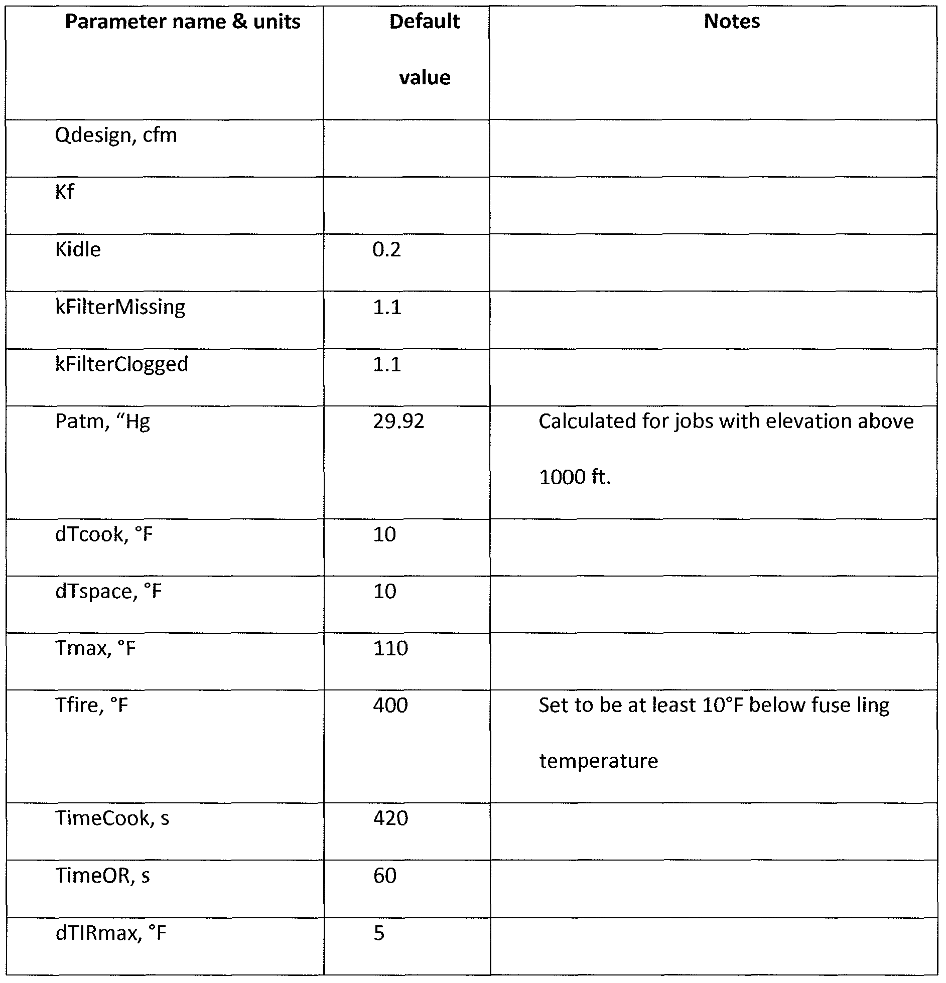
- control module 302 may include a list of the following examples of variables for each hood, as set forth below, in Tables 1-4:
- control module 302 may include a list of the following example variables for each hood, as set forth below in Tables 5-8: List of input variables for each hood
- control module processor 304 can be configured to use the following equation to calculate the exhaust air flow (Q) at exhaust temperature Tex:
- Kf is the hood coefficient.
- dp is the static pressure measured at the hood TAB port, in inches WC.
- Patm 29.92(1 - 0.0000068753 ⁇ ft) 5 ' 255 * £ q 3
- Mtot and Mtot_design are calculated per Eq. 4 Dens exh , is calculated per eq. Eq. 2 using actual and design temperatures of exhaust air.
- FIG. 5 illustrates a flow diagram for a start-up routine 500 which can be performed by the control module 302 of an embodiment having single or multiple hoods connected to a single exhaust fan, and without motorized balancing dampers at the hood level.
- the start-up routine 500 starts at S502 and can include one of the following three options to start the exhaust fan 316:
- the control module 302 can analyze a second reading as well before the system operation is started: At block S530, the exhaust temperature (Tex) can be measured with an exhaust temperature sensor 125. If the exhaust temperature exceeds a minimum preset exhaust temperature (Tex min) (block S535), the control module 302 can start the fan and set the exhaust air flow (Q) at (Qidle) (block S545). If the exhaust temperature (Tex) does not exceed the minimum exhaust temperature (Tex min), the control module 302 can turn the fan off (block S550). The start-up routine can be terminated after these steps are followed (block S550). [0067] 2) On schedule:
- Pre-programmable e.g., for a week
- schedule to switch on and switch off exhaust hoods.
- exhaust airflow (Q) is set to (Qidle).
- actuating of an override button on the hood can set hood exhaust airflow (Q) to (Qdesign) for the preset period of time (TimeOR).
- a flow diagram is provided showing a routine 600 which can be performed by the control module 302 to check the system 100 before the start of the flow control operation.
- the routine 600 can start at S602 and continue to a control module self-diagnostics process (block S605). If the self-diagnostic process is OK (block S610) the control module 302 can set the variable frequency drive (VFD) which controls the exhaust fan speed to a preset frequency (VFDidle) (block S615). Then the static pressure can be measured by a pressure transducer positioned at the hood TAB port (block S620) and the exhaust flow can be set to (Q) calculated using the formula of Eq. 1 (block S625).
- VFD variable frequency drive
- VFDidle preset frequency
- control module 302 can verify whether the (VFD) is the preset (VFDidle) and whether the exhaust air flow (Q) is less or exceeds (Qidle) by a threshold airflow coefficient (blocks S630, S645). Based on the exhaust airflow reading, the control module 302 generates and outputs appropriate error codes, which can be shown or displayed on an LCD display or other appropriate indicator 317 attached to the exhaust hood or coupled to the control module 302.
- a flow diagram is provided showing another routine 700 which can be performed by the control module 302 to check the system 200.
- the routine 700 can start at S702 and continue to a control module 302 self-diagnostics process (block S705). If a result of the self-diagnostic process is OK (block S710), the control module 302 can maintain the exhaust air flow (Q) at (Qidle) by maintaining the balancing dampers in their original or current position (block S715). Then, the static pressure (dp) is measured by the pressure transducer positioned at the hood TAB port (block S720), and the exhaust flow is set to (Q) calculated using Eq. 1 (block S725). If the self-diagnostics process fails, the control module can set the balancing dampers (BD) at open position and (VFD) at (VFDdesign) (block S730).
- BD balancing dampers
- the control module 302 can then check whether the balancing dampers are malfunctioning (block S735). If there is a malfunctioning balancing damper, the control module 302 can open the balancing dampers (block S740). If there is no malfunctioning balancing damper, then the control module 302 can check whether there is a malfunctioning sensor in the system (block S745). If there is a malfunctioning sensor, the control module 302 can set the balancing dampers at (BDPdesign), the (VFD) at (VFDdesign) and the exhaust airflow to (Qdesign) (block S750). Otherwise, the control module 302 can set (VFD) to (VFDidle) until the cooking appliance is turned off (block S755). This step terminates the routine (block S760).
- the hood 105 is automatically calibrated to design airflow (Qdesign).
- the calibration procedure routine 800 is illustrated in FIG. 8. The routine starts at S 802 and can be activated with all ventilation systems functioning and cooking appliances in the off state (blocks S805, S810).
- the calibration routine 800 can commence with the fan turned off (blocks S810, S870). If the fan is turned off, the hood can be balanced to the design airflow (Qdesign) (block S830). If the hood is not balanced (block S825), the control module 302 can adjust VFD (block S830) until the exhaust flow reaches (Qdesign) (block S835).
- the routine 800 then waits until the system is stabilized. Then, the hood 105 can be balanced for (Qidle) by reducing (VFD) speed (blocks S840, S845). The routine 800 once again waits until the system 100 is stabilized.
- the next step is to calibrate the sensors (block S850).
- the calibration of the sensors can be done during a first-time calibration mode, and is performed for cold cooking appliances and when there are no people present under the hood.
- the radiant temperature (IRT) can be measured and compared to a thermostat reading (Tspace), and the difference can be stored in the control module 302 memory 306 for each of the sensors (block S855).
- Tspace thermostat reading
- the change in the radiant temperature is measured again and is compared to the calibrated value stored in the memory 306 (block S855). If the reading is higher than a maximum allowed difference, a warning is generated in the control module 302 to clean the sensors (block S860).
- FIG. 9 illustrates the calibration routine 900 for a system with multiple hoods, one fan and no motorized balancing dampers.
- the routine 900 can follow substantially the same steps as for a single hood, single fan, and no motorized damper system shown above, except that for routine 900 every hood is calibrated.
- the routine 900 starts with Hood 1 and follows hood balancing steps as shown above (blocks S905-S930, and S985), as well as sensor calibration steps as shown above (blocks S935-S950).
- the airflow for the next hood is verified (block S955). If the airflow is at set point (Qdesign), the sensor calibration is repeated for the second (and any subsequent) hood (blocks S960, S965). If the airflow is not at the set point (Qdesign), the airflow and the sensor calibration can be repeated (S970) for the current hood. The routine 900 can be followed until all hoods in the system are calibrated (S965). The new design airflows for all hoods can be stored in the memory 306 (block S975) and control ends at S980.
- FIG. 10 illustrates the automatic calibration routine 1000 which may be performed by the second embodiment 200.
- the calibration routine 1000 all hoods are calibrated to design airflow (Qdesign) at minimum static pressure.
- the calibration procedure 1000 can be activated during the time the cooking equipment is not planned to be used with all hood filters in place, and repeated regularly (once a week for example).
- the routine 1000 can be activated at block S 1005.
- each hood can be balanced to achieve the design airflow (Qdesign) using the balancing dampers.
- Qdesign design airflow
- each BDP can be less than 1 (less than fully open). There may also be a waiting period in which the system stabilizes.
- FIG. 11 is a flow chart of a method 1100 to control the exhaust airflow as implemented in the various embodiments in accordance with the system 100.
- AS appliance status
- AS 0, which indicates that the corresponding cooking appliance is turned off.
- the exhaust temperature sensors 125 and the radiant IR sensors 120 can detect the appliance status and provide the detected status to the processor 175.
- the control module 302 can change the exhaust airflow (Q) in the system 100 to correspond to a predetermined airflow (Qdesign), a measured airflow (Q) (see below), and a predetermined (Qidle) airflow.
- the control module 302 can adjust the airflow (Q) to correspond to the predetermined (Qdesign) airflow.
- the control module 302 can adjust the airflow (Q) calculated according to the following equation: ,- > r ⁇ j ⁇ ( Tex - Tspace + dTspace ⁇
- control begins at Sl 102 and continues to block Sl 104, in which the appliance status can be determined based on the input received from the exhaust temperature sensors 125 and the IR temperature sensors 120.
- the exhaust temperature (Tex) and the ambient space temperature (Tspace) values can be read and stored in the memory 306 (block Sl 106) in order to calculate the exhaust airflow (Q) in the system (block Sl 108).
- the exhaust airflow (Q) can be calculated, for example, using equation Eq. 6.
- the operation 1100 may end at block Sl 158, with the control module 302 setting the airflow (Q) at the airflow level based on the determined appliance status (AS).
- FIGS. 12A-12C illustrate an exemplary method 1200 to control the exhaust airflow in a system 200 with motorized balancing dampers at each exhaust hood 105.
- FRT radiant temperature
- Tex exhaust temperature
- Tmin minimum value
- AS 1
- BDP fully opened position
- VFD fan 130 speed
- FIG. 13 is a block diagram of an exemplary exhaust flow control system in accordance with the present disclosure.
- a system 1300 includes a plurality of control modules (1302, 1308, and 1314) each coupled to respective ones of sensors (1304, 1310 and 1316, respectively), as described above (e.g., temperature, pressure, etc.), and outputs (1306, 1312, and 1318, respectively), as described above (e.g., motor control and damper control signals).
- the control modules can control their respective exhaust flow systems independently or in conjunction with each other. Further, the control modules can be in communication with each other.
- FIG. 14 is a block diagram of an exemplary exhaust flow control system in accordance with the present disclosure.
- a system 1400 includes a single control module 1402 coupled to a plurality of interfaces 1404-1408, which are each in turn coupled to respective sensors (1410-1414) and control outputs (1416-1420).
- the control module 1402 can monitor and control the exhaust flow rate for multiple hoods adjacent to multiple appliances. Each appliance can be independently monitored and an appropriate exhaust flow rate can be set as described above.
- the single control module 1402 may reduce costs and simplify maintenance for the exhaust flow control systems and allow an existing system to be upgraded or retrofitted to include the exhaust flow control method described above.
- FIG. 15 is a block diagram of an exemplary exhaust flow control system in accordance with the present disclosure.
- a system 1500 includes a control module 1502 coupled to sensors 1504 and control outputs 1506.
- the control module 1502 is also coupled to an alarm interface 1508, a fire suppression interface 1512, and an appliance communication interface 1516.
- the alarm interface 1508 is coupled to an alarm system 1510.
- the fire suppression interface 1512 is coupled to a fire suppression system 1514.
- the appliance communication interface 1516 is coupled to one or more appliances 1518-1520.
- the control module 1502 can communicate and exchange information with the alarm system 1510, fire suppression system 1514, and appliances 1518-1520 to better determine appliance states and a suitable exhaust flow rate. Also, the control module 1502 may provide information to the various systems (1510-1520) so that functions can be coordinated for a more effective operational environment. For example, the exhaust flow control module 1502, through its sensors 1504, may detect a fire or other dangerous condition and communicate this information to the alarm system 1510, the fire suppression system 1514, and the appliances 1518-1520 so that each device or system can take appropriate actions. Also, information from the appliances 1518-1520 can be used by the exhaust flow control system to more accurately determine appliance states and provide more accurate exhaust flow control.
- Embodiments of a method, system and computer program product for controlling exhaust flow rate may be implemented on a general-purpose computer, a special-purpose computer, a programmed microprocessor or microcontroller and peripheral integrated circuit element, an ASIC or other integrated circuit, a digital signal processor, a hardwired electronic or logic circuit such as a discrete element circuit, a programmed logic device such as a PLD, PLA, FPGA, PAL, or the like.
- any process capable of implementing the functions or steps described herein can be used to implement embodiments of the method, system, or computer program product for controlling exhaust flow rate.
- embodiments of the disclosed method, system, and computer program product for controlling exhaust flow rate may be readily implemented, fully or partially, in software using, for example, object or object-oriented software development environments that provide portable source code that can be used on a variety of computer platforms.
- embodiments of the disclosed method, system, and computer program product for controlling exhaust flow rate can be implemented partially or fully in hardware using, for example, standard logic circuits or a VLSI design.
- Other hardware or software can be used to implement embodiments depending on the speed and/or efficiency requirements of the systems, the particular function, and/or a particular software or hardware system, microprocessor, or microcomputer system being utilized.
- Embodiments of the method, system, and computer program product for controlling exhaust flow rate can be implemented in hardware and/or software using any known or later developed systems or structures, devices and/or software by those of ordinary skill in the applicable art from the functional description provided herein and with a general basic knowledge of the computer, exhaust flow, and/or cooking appliance arts.
- embodiments of the disclosed method, system, and computer program product for controlling exhaust flow rate can be implemented in software executed on a programmed general-purpose computer, a special purpose computer, a microprocessor, or the like.
- the exhaust flow rate control method of this invention can be implemented as a program embedded on a personal computer such as a JAVA® or CGI script, as a resource residing on a server or graphics workstation, as a routine embedded in a dedicated processing system, or the like.
- the method and system can also be implemented by physically incorporating the method for controlling exhaust flow rate into a software and/or hardware system, such as the hardware and software systems of exhaust vent hoods and/or appliances.
- VFD VFDdesign DCV - demand control ventilation
- dTIRcal - dTIR stored in the memory during first-time calibration procedure for each IR sensor.
- dTIRmax pre-set threshold value of absolute difference
- Exemplary default value is 9°F.
- FRT fluctuation of radiant temperature of appliance cooking surface, i - index, corresponding to hood number.
- IRT - infra red sensor temperature reading 0
- IRTmin Tspace + dTcook.
- kAirflowDesign ratio of mass exhaust airflows. Total actual airflow to total design airflow for hoods equipped with DCV Kf- hood coefficient, used to calculate hood exhaust airflow kFilterClogged - threshold airflow coefficient to detect clogged filter, default value 1.1 kFilterMissing - threshold airflow coefficient to detect filter missing, default value 1.1
- Kidle 1 - Qidle/Qdesign
- TimeOR - override time Time period when hood airflow is maintained at design level Q
Landscapes
- Engineering & Computer Science (AREA)
- Chemical & Material Sciences (AREA)
- Combustion & Propulsion (AREA)
- Mechanical Engineering (AREA)
- General Engineering & Computer Science (AREA)
- Physics & Mathematics (AREA)
- Fluid Mechanics (AREA)
- Signal Processing (AREA)
- Fuzzy Systems (AREA)
- Mathematical Physics (AREA)
- Human Computer Interaction (AREA)
- Health & Medical Sciences (AREA)
- Biomedical Technology (AREA)
- Ventilation (AREA)
- Air Conditioning Control Device (AREA)
Abstract
Description


Claims
Priority Applications (16)
| Application Number | Priority Date | Filing Date | Title |
|---|---|---|---|
| US13/132,542 US9494324B2 (en) | 2008-12-03 | 2009-12-03 | Exhaust flow control system and method |
| CA2745432A CA2745432C (en) | 2008-12-03 | 2009-12-03 | Exhaust flow control system and method |
| PL09831153T PL2370744T3 (en) | 2008-12-03 | 2009-12-03 | Exhaust flow control system and method |
| EP09831153.3A EP2370744B1 (en) | 2008-12-03 | 2009-12-03 | Exhaust flow control system and method |
| JP2011539713A JP5767974B2 (en) | 2008-12-03 | 2009-12-03 | Exhaust flow control system and method |
| AU2009322238A AU2009322238C1 (en) | 2008-12-03 | 2009-12-03 | Exhaust flow control system and method |
| SG2011039443A SG171458A1 (en) | 2008-12-03 | 2009-12-03 | Exhaust flow control system and method |
| BRPI0917043 BRPI0917043B1 (en) | 2008-12-03 | 2009-12-03 | Method for controlling exhaust air flow in an exhaust ventilation system, and exhaust ventilation system |
| CN2009801560633A CN102301187A (en) | 2008-12-03 | 2009-12-03 | Exhaust flow control system and method |
| DK09831153.3T DK2370744T3 (en) | 2008-12-03 | 2009-12-03 | Extraction flow control system and method |
| RU2011122417/03A RU2524104C2 (en) | 2008-12-03 | 2009-12-03 | Exhaust flow control system and method |
| MX2011005770A MX2011005770A (en) | 2008-12-03 | 2009-12-03 | Exhaust flow control system and method. |
| ZA2011/03916A ZA201103916B (en) | 2008-12-03 | 2011-05-27 | Exhaust flow control system and method |
| AU2016200838A AU2016200838B2 (en) | 2008-12-03 | 2016-02-10 | Exhaust flow control system and method |
| US15/196,693 US10082299B2 (en) | 2008-12-03 | 2016-06-29 | Exhaust flow control system and method |
| US16/114,769 US20180363923A1 (en) | 2008-12-03 | 2018-08-28 | Exhaust Flow Control System and Method |
Applications Claiming Priority (4)
| Application Number | Priority Date | Filing Date | Title |
|---|---|---|---|
| US11971608P | 2008-12-03 | 2008-12-03 | |
| US61/119,716 | 2008-12-03 | ||
| US18516809P | 2009-06-08 | 2009-06-08 | |
| US61/185,168 | 2009-06-08 |
Related Child Applications (2)
| Application Number | Title | Priority Date | Filing Date |
|---|---|---|---|
| US13/132,542 A-371-Of-International US9494324B2 (en) | 2008-12-03 | 2009-12-03 | Exhaust flow control system and method |
| US15/196,693 Continuation US10082299B2 (en) | 2008-12-03 | 2016-06-29 | Exhaust flow control system and method |
Publications (1)
| Publication Number | Publication Date |
|---|---|
| WO2010065793A1 true WO2010065793A1 (en) | 2010-06-10 |
Family
ID=42233620
Family Applications (1)
| Application Number | Title | Priority Date | Filing Date |
|---|---|---|---|
| PCT/US2009/066660 WO2010065793A1 (en) | 2008-12-03 | 2009-12-03 | Exhaust flow control system and method |
Country Status (15)
| Country | Link |
|---|---|
| US (3) | US9494324B2 (en) |
| EP (1) | EP2370744B1 (en) |
| JP (3) | JP5767974B2 (en) |
| CN (2) | CN102301187A (en) |
| AU (2) | AU2009322238C1 (en) |
| BR (1) | BRPI0917043B1 (en) |
| CA (1) | CA2745432C (en) |
| DK (1) | DK2370744T3 (en) |
| HK (1) | HK1224359A1 (en) |
| MX (1) | MX2011005770A (en) |
| PL (1) | PL2370744T3 (en) |
| RU (1) | RU2524104C2 (en) |
| SG (1) | SG171458A1 (en) |
| WO (1) | WO2010065793A1 (en) |
| ZA (1) | ZA201103916B (en) |
Cited By (21)
| Publication number | Priority date | Publication date | Assignee | Title |
|---|---|---|---|---|
| CN102393036A (en) * | 2011-09-24 | 2012-03-28 | 广东工业大学 | Mounting structure for range hood with sensor |
| WO2012114736A1 (en) * | 2011-02-25 | 2012-08-30 | パナソニック株式会社 | Extractor hood |
| CN102679505A (en) * | 2012-06-13 | 2012-09-19 | 重庆大学 | Room temperature control method |
| JP2012220096A (en) * | 2011-04-08 | 2012-11-12 | Panasonic Corp | Range hood fan |
| WO2013038194A1 (en) * | 2011-09-13 | 2013-03-21 | Sirius Products Limited | An air extraction system |
| ITTO20120341A1 (en) * | 2012-04-17 | 2013-10-18 | Indesit Co Spa | HOOD WITH INSTALLATION CONTROL AND METHOD FOR ITS IMPLEMENTATION |
| EP2746681A1 (en) * | 2012-12-20 | 2014-06-25 | Diehl AKO Stiftung & Co. KG | Extractor hood and method for controlling the operation of an extractor hood |
| WO2014139806A1 (en) * | 2013-03-11 | 2014-09-18 | BSH Bosch und Siemens Hausgeräte GmbH | Method for determining an operating state of an extractor hood assembly |
| RU2534942C2 (en) * | 2010-07-15 | 2014-12-10 | Сименс Швайц Аг | Detection of blockages and interruptions in aspirating smoke detector (asd) |
| NO20151317A1 (en) * | 2014-10-07 | 2016-04-08 | Thermex Scandinavia As | extraction system |
| WO2017031044A1 (en) * | 2015-08-14 | 2017-02-23 | Tyco Fire Products Lp | Filter clogging monitoring systems and methods |
| US9702566B2 (en) | 2014-01-28 | 2017-07-11 | Illinois Tool Works Inc. | Cooking exhaust hood ventilation system and related methods |
| US9909765B2 (en) | 2011-07-07 | 2018-03-06 | Oy Halton Group Ltd. | Exhaust hood methods, devices, and systems |
| EP3346196A1 (en) | 2012-06-07 | 2018-07-11 | OY Halton Group Ltd. | Method of regulating flow trough ventilation hood and fire detection by means of sensor |
| WO2018175495A1 (en) * | 2017-03-20 | 2018-09-27 | Oy Halton Group Ltd. | Fire safety devices methods and systems |
| US10195470B2 (en) | 2013-03-15 | 2019-02-05 | Oy Halton Group Ltd. | Water spray fume cleansing with demand-based operation |
| IT201900003805A1 (en) * | 2019-03-15 | 2020-09-15 | Rational Ag | PROCEDURE FOR CHECKING A COOKING DEVICE, COOKING DEVICE AND COOKING SYSTEM |
| US20220113034A1 (en) * | 2018-11-29 | 2022-04-14 | Broan-Nutone Llc | Smart indoor air venting system |
| EP4043799A1 (en) * | 2021-02-16 | 2022-08-17 | Electrolux Appliances Aktiebolag | Extractor hood for a hob and method for operating an extractor hood |
| EP4276364A1 (en) * | 2022-05-13 | 2023-11-15 | Arçelik Anonim Sirketi | An exhaust hood with improved automatic operation performance |
| EP4276363A1 (en) * | 2022-05-13 | 2023-11-15 | Arçelik Anonim Sirketi | An exhaust hood with improved automatic operation performance |
Families Citing this family (53)
| Publication number | Priority date | Publication date | Assignee | Title |
|---|---|---|---|---|
| MX2008013396A (en) * | 2006-04-18 | 2009-01-20 | Halton Group Ltd Oy | Recirculating exhaust system. |
| US20090061752A1 (en) | 2007-08-28 | 2009-03-05 | Current Energy Controls, Lp | Autonomous Ventilation System |
| US20120055275A1 (en) * | 2010-09-02 | 2012-03-08 | Streivor Air Systems, Inc. | System and Method for Smart Operation of an Exhaust Hood Using a Protected Monitoring Device |
| US20120083198A1 (en) * | 2010-10-01 | 2012-04-05 | Broan-NuTone Company , LLC | Fluid cleaning system and method |
| US9109805B2 (en) * | 2012-01-19 | 2015-08-18 | General Electric Company | Range hood with temperature detection and notification |
| SE537339C2 (en) * | 2012-06-25 | 2015-04-07 | Medicvent Ab | A central flow system |
| US20140017989A1 (en) * | 2012-07-16 | 2014-01-16 | Solar Turbines Inc. | Power system enclosure |
| US9605860B2 (en) * | 2012-11-02 | 2017-03-28 | Flextronics Ap, Llc | Energy saving-exhaust control and auto shut off system |
| WO2015071898A1 (en) * | 2013-11-18 | 2015-05-21 | Aps Technologies (Hong Kong) Limited | Kitchen hood device |
| FI20145134L (en) * | 2014-02-12 | 2015-08-13 | SeaKing Oy | Extractor hood |
| US20150302569A1 (en) * | 2014-04-22 | 2015-10-22 | General Electric Company | Sensing system for a cooktop appliance with airflow protected sensor |
| US10767876B2 (en) * | 2014-12-24 | 2020-09-08 | Koninklijke Philips N.V. | Systems and methods for monitoring air quality and events likely to affect air quality, and taking remedial action |
| US10434345B2 (en) * | 2015-02-18 | 2019-10-08 | Tyco Fire Products Lp | Fire protection systems and methods for ventilation hoods |
| FI128643B (en) * | 2015-03-16 | 2020-09-30 | Air D Fin Oy | Intelligent ventilation system |
| CN104819500B (en) * | 2015-05-18 | 2017-05-03 | 广东美的厨房电器制造有限公司 | Extractor hood as well as gas flow detection method, device and air speed control method |
| US10767873B2 (en) * | 2015-07-06 | 2020-09-08 | Koninklijke Philips N.V. | Air processing system and method |
| KR101624607B1 (en) * | 2015-09-22 | 2016-05-27 | 주식회사 인솔엔지니어링 | Control system and method for kitchen ventilation |
| DE102015122618A1 (en) * | 2015-12-22 | 2017-06-22 | Frima International Ag | System with cooking appliance and ventilation system and method for controlling such a system |
| GB2547678A (en) * | 2016-02-25 | 2017-08-30 | Johnson Electric Sa | Method of maintaining a position of an airflow-direction control element of a HVAC system |
| JP6656054B2 (en) * | 2016-03-31 | 2020-03-04 | 大阪瓦斯株式会社 | Ventilation device and calculation method |
| IT201600092209A1 (en) * | 2016-09-13 | 2018-03-13 | P G A Srl | SYSTEM FOR AUTOMATIC STARTING, ADJUSTMENT AND / OR SHUTDOWN OF ONE OR MORE ACCESSORIES FOR COOKING OR SIMILAR PLANS |
| FI128693B (en) * | 2016-11-08 | 2020-10-15 | Climecon Oy | Method for the identification of the structure of a ventilation system |
| CN108253474B (en) * | 2016-12-29 | 2023-10-20 | 宁波方太厨具有限公司 | Intelligent range hood and control method thereof |
| US10458669B2 (en) | 2017-03-29 | 2019-10-29 | Johnson Controls Technology Company | Thermostat with interactive installation features |
| CN110506184B (en) * | 2017-03-31 | 2021-07-06 | 松下知识产权经营株式会社 | Ventilation system and heat exchange type ventilator |
| WO2018191699A1 (en) | 2017-04-14 | 2018-10-18 | Johnson Controls Technology Company | Multi-function thermostat with intelligent supply fan control for maximizing air quality and optimizing energy usage |
| WO2018191635A1 (en) | 2017-04-14 | 2018-10-18 | Johnson Controls Technology Company | Thermostat with occupancy detection via proxy |
| WO2018191703A1 (en) | 2017-04-14 | 2018-10-18 | Johnson Controls Technology Company | Thermostat with preemptive heating, cooling, and ventilation in response to elevated occupancy detection via proxy |
| US11162698B2 (en) | 2017-04-14 | 2021-11-02 | Johnson Controls Tyco IP Holdings LLP | Thermostat with exhaust fan control for air quality and humidity control |
| EP3610203A4 (en) | 2017-04-14 | 2021-01-06 | Johnson Controls Technology Company | Multi-function thermostat with intelligent ventilator control for frost/mold protection and air quality control |
| WO2018191510A1 (en) | 2017-04-14 | 2018-10-18 | Johnson Controls Technology Company | Multi-function thermostat with air quality display |
| WO2018193495A1 (en) * | 2017-04-17 | 2018-10-25 | 株式会社島津製作所 | Emission spectrometer |
| CN107991433B (en) * | 2017-11-09 | 2021-07-06 | 广州视源电子科技股份有限公司 | Smoke value processing method and system, readable storage medium and smoke processing equipment |
| CN107781886B (en) * | 2017-11-27 | 2019-07-19 | 杨肇 | One kind zero and formula low-carbon oil fume purifier and purification system |
| US11131474B2 (en) | 2018-03-09 | 2021-09-28 | Johnson Controls Tyco IP Holdings LLP | Thermostat with user interface features |
| CN110513812A (en) * | 2018-05-22 | 2019-11-29 | 广州松下空调器有限公司 | A kind of air conditioning control method and air conditioner |
| KR102037833B1 (en) * | 2018-05-25 | 2019-10-29 | 린나이코리아 주식회사 | Apparatus and method for controling a range hood of lifting type for kitchen |
| US10788222B2 (en) * | 2018-08-03 | 2020-09-29 | Haier Us Appliance Solutions, Inc. | Cooking exhaust systems having one or more airflow features |
| US10627118B2 (en) * | 2018-08-03 | 2020-04-21 | Haier Us Appliance Solutions, Inc. | Cooking engagement system equipped with humidity sensor |
| KR102002078B1 (en) * | 2018-11-13 | 2019-07-24 | 주식회사 제이텍 | A kitchen hood system for controlling air supply and exhaust airflow in accordance with the setting conditions of the air conditioning system and its control method |
| US11796187B2 (en) * | 2018-12-10 | 2023-10-24 | Midea Group Co., Ltd. | Electronically controlled vent damper |
| JP7365681B2 (en) * | 2019-02-14 | 2023-10-20 | 富士工業株式会社 | Range food |
| US10989416B2 (en) | 2019-03-11 | 2021-04-27 | Spring Air Systems Inc. | Damper for kitchen exhaust hood |
| WO2020206227A1 (en) | 2019-04-04 | 2020-10-08 | Oy Halton Group Ltd. | Slide-type range hood |
| KR102266306B1 (en) * | 2019-07-09 | 2021-06-16 | 심창섭 | Generation ventilation system using fan separated type range hood |
| US11835250B2 (en) * | 2020-01-09 | 2023-12-05 | Carrier Corporation | Method and a system for performing calibration of variable air volume (VAV) units |
| CN111412506B (en) * | 2020-03-31 | 2022-04-15 | 佛山市顺德区美的洗涤电器制造有限公司 | Starting detection method and device of cooking equipment, range hood and storage medium |
| US11859848B2 (en) * | 2020-06-30 | 2024-01-02 | Johnson Controls Tyco IP Holdings LLP | Building control system using a control device position as a proxy for static pressure in a conduit |
| CN112178720B (en) * | 2020-09-18 | 2022-11-04 | 华帝股份有限公司 | Control method of smoke collection and exhaust machine and smoke collection and exhaust system applying control method |
| CN113266863A (en) * | 2021-06-28 | 2021-08-17 | 火星人厨具股份有限公司 | Kitchen ventilator air inlet blockage detection device and method |
| CN113693433A (en) * | 2021-08-12 | 2021-11-26 | 宁波方太厨具有限公司 | Exhaust control method of steam box, steam box and computer readable storage medium |
| BE1030951B1 (en) * | 2022-10-10 | 2024-05-14 | Renson Ventilation Nv | METHOD FOR CONTROLLING A CENTRAL VENTILATION SYSTEM AND VENTILATION SYSTEM CONFIGURED FOR EXECUTING THIS METHOD |
| CN117410995B (en) * | 2023-12-04 | 2024-04-02 | 河南柏科沃电子科技有限公司 | Self-adaptive adjusting type active power filter |
Citations (8)
| Publication number | Priority date | Publication date | Assignee | Title |
|---|---|---|---|---|
| DE2518750A1 (en) | 1975-04-26 | 1976-11-04 | Ego Regeltech | Vapour extractor hood with infinite adjustment - uses temp. difference between fumes and atmosphere to start ventilator |
| DE3909125A1 (en) | 1989-03-20 | 1990-09-27 | Diehl Gmbh & Co | Control device of a vapour extraction hood |
| US6170480B1 (en) | 1999-01-22 | 2001-01-09 | Melink Corporation | Commercial kitchen exhaust system |
| US20030206572A1 (en) * | 2000-12-21 | 2003-11-06 | Ralf Dorwarth | Method and device for determining the temperature of a cooking vessel |
| US20060032492A1 (en) * | 2001-01-23 | 2006-02-16 | Rick Bagwell | Real-time control of exhaust flow |
| US7131549B2 (en) * | 2002-10-18 | 2006-11-07 | Oldemark Llc | Double sided grill with automated control including localized prompting and confirmation of manual operations |
| WO2008065332A2 (en) | 2006-11-27 | 2008-06-05 | Michael Leon Shaw | A kitchen ventilation system |
| US20080274683A1 (en) | 2007-05-04 | 2008-11-06 | Current Energy Controls, Lp | Autonomous Ventilation System |
Family Cites Families (251)
| Publication number | Priority date | Publication date | Assignee | Title |
|---|---|---|---|---|
| DE314477C (en) | 1900-01-01 | |||
| US2833615A (en) | 1952-10-03 | 1958-05-06 | Houdry Process Corp | Abatement of smog in flue gases |
| US2853367A (en) | 1954-02-10 | 1958-09-23 | Oxy Catalyst Inc | Cartridge type catalytic exhaust cleaner |
| US2743529A (en) | 1954-07-06 | 1956-05-01 | Oxy Catalyst Inc | Drying oven and operation thereof |
| US2862095A (en) | 1954-10-07 | 1958-11-25 | Philco Corp | Vapor treating means |
| CH334686A (en) | 1955-09-12 | 1958-12-15 | Ingenieurbureau W Hausammann & | Changeable nozzle, especially Laval nozzle for wind tunnels |
| US2933080A (en) | 1956-03-07 | 1960-04-19 | Oxy Catalyst Inc | Cooking apparatus |
| JPS4113143Y1 (en) | 1964-04-02 | 1966-06-22 | ||
| FR1418065A (en) | 1964-07-16 | 1965-11-19 | Loire Atel Forges | Method and device for regulating the capture of oxygen refining gases |
| US3381134A (en) | 1964-10-05 | 1968-04-30 | Philip C. Wolf | Mass flow indicating means including an interferometer system |
| US3254588A (en) | 1965-05-24 | 1966-06-07 | Truhan Andrew | Laboratory fume hood |
| US3323439A (en) | 1966-01-28 | 1967-06-06 | Weaver | Damper and fire control device for ventilators |
| US3400649A (en) | 1967-01-26 | 1968-09-10 | Donald D. Jensen | Ventilating system including fume removal means |
| US3457850A (en) | 1967-12-11 | 1969-07-29 | Elster S Air Conditioning | Air curtain ventilator |
| US3536457A (en) | 1968-02-21 | 1970-10-27 | Gen Electric | Catalytic oxidation unit for domestic oven exhaust |
| SE339300B (en) | 1968-05-14 | 1971-10-04 | Electrolux Ab | |
| US3513766A (en) | 1968-06-24 | 1970-05-26 | Willard K Ahlrich | Ventilating hood |
| FR2030532A5 (en) | 1969-07-03 | 1970-11-13 | Snecma | |
| JPS5248645Y1 (en) | 1969-11-11 | 1977-11-05 | ||
| US3690245A (en) | 1970-09-17 | 1972-09-12 | Panacon Corp | Range hood unit with fire safeguard fan control system |
| US3752056A (en) | 1970-11-04 | 1973-08-14 | Sheldon And Co E | Laboratory exhaust hood |
| GB1377831A (en) | 1972-04-17 | 1974-12-18 | Secr Defence | Interferometers for fluid flow measurements |
| US3809480A (en) | 1972-07-24 | 1974-05-07 | Gen Dynamics Corp | Method and apparatus for surveying the velocities of a flow field |
| GB1450911A (en) | 1973-01-17 | 1976-09-29 | Nat Res Dev | Laser doppler velocimetry |
| US3829285A (en) | 1973-02-28 | 1974-08-13 | Mc Quay Perfex Inc | Recuperators for incinerators |
| US3952640A (en) | 1973-03-01 | 1976-04-27 | Vent-Cair, Inc. | Apparatus and method for extracting grease and smoke, and method of installing the same |
| US3895569A (en) | 1973-09-26 | 1975-07-22 | Ind Clean Air Inc | Air modulating fume system |
| US3943836A (en) | 1974-08-15 | 1976-03-16 | Vent-Cair, Inc. | Apparatus for removing fumes from the space above a cooking appliance in a restaurant |
| CA1081030A (en) | 1974-09-26 | 1980-07-08 | Irvin R. Kuechler | Method of installing kitchen grease hood |
| US4056877A (en) | 1974-09-26 | 1977-11-08 | Vent-Cair, Inc. | Method of installing apparatus for extracting grease and smoke |
| US3978777A (en) | 1975-02-24 | 1976-09-07 | Nett Louis A | Ventilating apparatus |
| CA1069749A (en) | 1975-02-24 | 1980-01-15 | Econovent Systems | Ventilating apparatus |
| US4047519A (en) | 1975-02-24 | 1977-09-13 | Nett Louis A | Ventilating apparatus |
| DE2640684C2 (en) | 1975-09-11 | 1981-11-26 | Matsushita Electric Industrial Co., Ltd., Kadoma, Osaka | Roasting or cooking oven |
| US4147502A (en) | 1975-09-15 | 1979-04-03 | Roper Corporation | System for control of thermal potential |
| US4043319A (en) | 1975-09-18 | 1977-08-23 | Jensen Donald D | Exhaust hood |
| US4085736A (en) | 1975-10-01 | 1978-04-25 | Vent-Cair, Inc. | Grease-hood apparatus |
| JPS5248645A (en) | 1975-10-14 | 1977-04-18 | Kuraray Co Ltd | Process for preparation of cyclic terpene derivatives having carbonyl group |
| US4050368A (en) | 1976-01-02 | 1977-09-27 | Marion L. Eakes Co. | Exhaust system for industrial processes |
| US4117833A (en) | 1977-02-16 | 1978-10-03 | Mueller Robert H | Exhaust hood with adjustable air injection nozzle |
| US4134394A (en) | 1977-02-24 | 1979-01-16 | Otenbaker James T | Air ventilation system |
| US4105015A (en) | 1977-03-09 | 1978-08-08 | William C. Isom | Exhaust hood energy saving device |
| US4109641A (en) | 1977-05-25 | 1978-08-29 | Air Master Systems, Inc. | Adapter manifold for ventilation hood |
| US4146017A (en) | 1977-08-08 | 1979-03-27 | Overton Jr Duncan E | Hood system for cooking equipment |
| US4155348A (en) | 1977-10-11 | 1979-05-22 | Ahlrich Wilard K | Ventilating apparatus |
| US4213947A (en) | 1977-10-13 | 1980-07-22 | Champion International Corporation | Emission control system and method |
| US4160407A (en) | 1977-11-18 | 1979-07-10 | Bell Telephone Laboratories, Incorporated | Ventilating system |
| US4153044A (en) | 1978-01-23 | 1979-05-08 | Nett Louis A | Backshelf ventilating hood |
| US4138220A (en) | 1978-02-13 | 1979-02-06 | Colonial Metals, Inc. | Apparatus for catalytic oxidation of grease and fats in low temperature fumes |
| US4211154A (en) | 1978-09-20 | 1980-07-08 | Eakes Marion L | Apparatus for improving the collection of gases into a suction orifice |
| US4475534A (en) | 1978-11-30 | 1984-10-09 | Moriarty Daniel J | Ventilating system for kitchen stove |
| US4286572A (en) | 1979-03-08 | 1981-09-01 | Cambridge Engineering, Inc. | Ventilating hood |
| US4285390A (en) | 1979-04-16 | 1981-08-25 | Stainless Equipment Company | Method of and apparatus for supplying treated air to spaces having different cooling requirements |
| SE419830B (en) | 1979-05-21 | 1981-08-31 | Leif Ingemar Lind | SET AND DEVICE FOR EXHAUSTING POLLUTANEATED AIR |
| GB2054143B (en) | 1979-07-11 | 1983-06-29 | Atomic Energy Authority Uk | Measurement of the size of particles dispersed in a fluid |
| US4287405A (en) | 1979-10-02 | 1981-09-01 | Mitsubishi Jukogyo Kabushiki Kaisha | Process and apparatus for exhausting fumes produced by arc welding |
| US4373507A (en) | 1980-10-09 | 1983-02-15 | Jamestown Group | Stove construction |
| US4346692A (en) | 1980-11-26 | 1982-08-31 | Mccauley Lewis C | Make-up air device for range hood |
| US4350166A (en) | 1980-12-12 | 1982-09-21 | Honeywell Inc. | Apnea detector |
| US4467782A (en) | 1981-08-19 | 1984-08-28 | Russell Robert E | Ventilating system for use with devices which produce airborne impurities |
| US4398415A (en) | 1981-12-10 | 1983-08-16 | The United States Of America As Represented By The Secretary Of The Air Force | Swing link flexible wind tunnel nozzle |
| US4497242A (en) | 1982-02-11 | 1985-02-05 | Barber-Colman Company | Ventilation control system |
| GB2132335A (en) | 1982-12-21 | 1984-07-04 | Chung Tsung Cheng | Apparatus for exhausting gaseous emissions during cooking |
| SE8305034L (en) | 1983-09-19 | 1985-03-20 | Bahco Ventilation Ab | extraction facility |
| US4483316A (en) | 1983-10-11 | 1984-11-20 | Alco Foodservice Equipment Company | Air ventilation system |
| US4484563A (en) | 1983-10-11 | 1984-11-27 | Alco Foodservice Equipment Company | Air ventilation and pollution cleaning system |
| US4528898A (en) | 1984-03-05 | 1985-07-16 | Imec Corporation | Fume hood controller |
| FI77163C (en) | 1984-03-09 | 1989-02-10 | Halton Oy | Air Purifier |
| JPS60213753A (en) | 1984-04-09 | 1985-10-26 | Matsushita Seiko Co Ltd | Clean bench |
| US4556046A (en) | 1984-04-12 | 1985-12-03 | Pizza Hut, Inc. | Hood for oven in pizza delivery vehicle |
| US4586486A (en) | 1984-07-06 | 1986-05-06 | National Air Systems, Inc. | Multilevel air distribution panel for air ventilation hood |
| FI71831C (en) | 1985-04-12 | 1987-02-09 | Halton Oy | FRAONLUFTSANORDNING. |
| US4617909A (en) | 1985-05-06 | 1986-10-21 | Molitor Victor D | Method of and device for preventing smoke curling from underneath the hood of a grease extraction ventilator |
| US4823015A (en) | 1985-05-08 | 1989-04-18 | Adt, Inc. | Electrical interference free projected beam smoke detector |
| DE3519189A1 (en) | 1985-05-29 | 1986-12-04 | Buderus Ag, 6330 Wetzlar | Vapour extractor hood |
| US4781460A (en) | 1986-01-08 | 1988-11-01 | Coulter Electronics Of New England, Inc. | System for measuring the size distribution of particles dispersed in a fluid |
| US4655194A (en) | 1986-04-15 | 1987-04-07 | Heat Transfer Specialties, Inc. | System for removing fumes |
| JPS6391442A (en) | 1986-10-06 | 1988-04-22 | Aruku Kk | Ventilating method for smoke, etc. generated from gas range |
| DE3639929A1 (en) | 1986-11-22 | 1988-06-01 | Babcock Bsh Ag | CONTINUOUS DRYER FOR VENEER BLADES |
| US4773311A (en) | 1986-11-24 | 1988-09-27 | Phoenix Controls Corporation | Make up air controller for use with fume hood systems |
| FI83696B (en) | 1987-01-27 | 1991-04-30 | Halton Oy | FOERFARANDE FOER REGLERING AV VENTILATION. |
| JPH0788827B2 (en) * | 1987-03-31 | 1995-09-27 | 三菱電機株式会社 | Blower operation controller |
| JPS63251741A (en) | 1987-04-08 | 1988-10-19 | Nagano Pref Gov Roudou Kijiyun Kyokai Rengokai | Velocity gradient air curtain device |
| DE3716257A1 (en) | 1987-05-15 | 1988-11-24 | Takeo Imai | METHOD AND DEVICE FOR COLLECTING POLLUTED SUBSTANCES |
| US4788905A (en) | 1987-06-10 | 1988-12-06 | Kohorn H Von | Combination cooking, eating and ventilating system |
| US4793715A (en) | 1987-08-28 | 1988-12-27 | Westinghouse Electric Corp. | Detector for aligning high power lasers |
| JPS6484039A (en) | 1987-09-24 | 1989-03-29 | Matsushita Electric Works Ltd | Smoke venting hood |
| US4921509A (en) | 1987-10-30 | 1990-05-01 | Micro-Technology Licensing Corporation | Air filtration system for ducted range hoods |
| US5033508A (en) | 1987-12-23 | 1991-07-23 | Coyne & Delany Co. | Sensor operated water flow control |
| AT390325B (en) | 1988-03-11 | 1990-04-25 | Tabarelli Werner | INTERFEROMETRIC DEVICE FOR MEASURING CHANGES IN POSITION OF A MOVING COMPONENT |
| US5063834A (en) | 1988-06-10 | 1991-11-12 | Halton Oy | Focussed ventilation procedure and focussed ventilation means |
| JPH0233552A (en) | 1988-07-21 | 1990-02-02 | Matsushita Seiko Co Ltd | Oven range hood |
| US5251608A (en) | 1988-08-19 | 1993-10-12 | Cameron Cote | Air canopy ventilation system |
| CA1272064A (en) | 1988-08-19 | 1990-07-31 | Cameron Cote | Air canopy cooking system |
| US4903685A (en) | 1989-01-24 | 1990-02-27 | Melink Stephen K | Variable exhaust controller for commercial kitchens |
| US4934256A (en) | 1989-02-14 | 1990-06-19 | Labconco Corporation | Fume hood ventilation control system |
| JP2602326B2 (en) | 1989-04-28 | 1997-04-23 | 株式会社日立製作所 | Automatic ventilation device |
| US4944285A (en) * | 1989-05-25 | 1990-07-31 | Glassman Joseph T | Exhaust hood for pizza ovens |
| DE3918870C2 (en) | 1989-06-09 | 1995-06-29 | Roehl Hager Hannelore | Process and device for extracting vapors and vapors |
| US4944283A (en) | 1989-08-29 | 1990-07-31 | Paloma Kogyo Kabushiki Kaisha | Gas burner |
| JPH0391616A (en) * | 1989-09-05 | 1991-04-17 | Toshiba Corp | System range hood fan |
| US4974579A (en) | 1989-09-28 | 1990-12-04 | Rheem Manufacturing Company | Induced draft, fuel-fired furnace apparatus having an improved, high efficiency heat exchanger |
| FI88433C (en) | 1990-01-31 | 1994-08-17 | Halton Oy | Anordning Foer ingaongs- och utgaongsluft och luftkonditioneringsfoerfarande |
| FI84096B (en) | 1990-01-31 | 1991-06-28 | Halton Oy | UNDERTAKSKONSTRUKTION OCH FOERFARANDE FOER ATT BRINGA LUFTEN ATT STROEMMA I SAMBAND MED UNDERTAKSKONSTRUKTIONEN. |
| JPH03247937A (en) | 1990-02-23 | 1991-11-06 | Mitsubishi Electric Corp | Range hood |
| CH682512A5 (en) | 1990-03-02 | 1993-09-30 | Zurecon Ag | Steam extractor hood for cooking hob - has ventilation fan providing air curtain around hub surface to prevent mixing between steam and room air |
| US5147429A (en) | 1990-04-09 | 1992-09-15 | James Bartholomew | Mobile airborne air cleaning station |
| JP2654227B2 (en) | 1990-04-13 | 1997-09-17 | 株式会社熊谷組 | Exhaust method |
| CH680834A5 (en) | 1990-06-19 | 1992-11-30 | Analyse Data Finance Sa | |
| JP2626189B2 (en) | 1990-06-29 | 1997-07-02 | コクヨ株式会社 | Smoking equipment |
| JP3134159B2 (en) | 1990-07-05 | 2001-02-13 | 株式会社トルネックス | Artificial tornado generating mechanism, device therefor, and lighting device using the same |
| JPH04113143A (en) | 1990-08-31 | 1992-04-14 | Kansai Electric Power Co Inc:The | Range device for kitchen |
| US5090303A (en) | 1990-09-28 | 1992-02-25 | Landis & Gyr Powers, Inc. | Laboratory fume hood control apparatus having improved safety considerations |
| US5092227B1 (en) | 1990-09-28 | 1995-02-14 | Landis & Gyr Powers Inc | Apparatus for controlling the ventilation of laboratory fume hoods |
| US5115728A (en) | 1990-09-28 | 1992-05-26 | Landis & Gyr Powers, Inc. | System for controlling the differential pressure of a room having laboratory fume hoods |
| US5764579A (en) | 1990-10-01 | 1998-06-09 | American Auto-Matrix, Inc. | System for controlling laboratories with fume hoods |
| US5139009A (en) | 1990-10-11 | 1992-08-18 | Walsh Leo B | Exhaust ventilation control system |
| DK166229C (en) | 1990-11-02 | 1993-08-16 | Netavent As | VENTILATION |
| IT1244170B (en) | 1990-12-04 | 1994-07-08 | Cise Spa | LASER EQUIPMENT FOR MEASURING THE SPEED OF A FLUID. |
| DE4114329A1 (en) | 1991-05-02 | 1992-11-05 | Standard Elektrik Lorenz Ag | Extractor hood over cooker to remove steam and fumes - comprises hood open on underside and with discharge opening on top and equipped with fan |
| US5215497A (en) | 1991-07-10 | 1993-06-01 | Johnson Service Company | Fume hood controller |
| US5205783A (en) | 1991-08-22 | 1993-04-27 | Accu*Aire Systems, Inc. | Air flow control equipment in chemical laboratory buildings |
| US5240455A (en) | 1991-08-23 | 1993-08-31 | Phoenix Controls Corporation | Method and apparatus for controlling a fume hood |
| US5215075A (en) | 1991-09-27 | 1993-06-01 | Heat And Control, Inc. | Cooking system having an efficient pollution incinerating heat exchanger |
| DE4203916C1 (en) | 1992-02-11 | 1993-04-29 | Hannelore 8400 Regensburg De Roehl-Hager | |
| JPH05248645A (en) | 1992-03-03 | 1993-09-24 | Shinritsu Denki Kk | Electromagnetic cooking device for kitchen |
| FI96901C (en) | 1992-04-16 | 1996-09-10 | Halton Oy | Method and apparatus for controlling and silencing an air stream |
| JPH05322242A (en) * | 1992-05-15 | 1993-12-07 | Tokyo Gas Co Ltd | Air supplying and discharging method and device for kitchen room |
| US5622100A (en) | 1992-07-31 | 1997-04-22 | Ayrking Corporation | Catalytic assembly for cooking smoke abatement |
| US5311930A (en) | 1992-11-17 | 1994-05-17 | Bruenn Paul R | Heat reclamation device |
| US5406073A (en) | 1993-01-25 | 1995-04-11 | Phoenix Controls Corporation | System for detecting a movable entity within a selected space |
| DK0612962T3 (en) | 1993-02-23 | 1995-04-10 | Maimer Gmbh | Hood, especially for use in industrial kitchens |
| US5414509A (en) | 1993-03-08 | 1995-05-09 | Associated Universities, Inc. | Optical pressure/density measuring means |
| US5470275A (en) | 1993-04-05 | 1995-11-28 | Landis & Gyr Powers, Inc. | Method and apparatus for controlling fume hood face velocity using variable by-pass resistance |
| FR2705766B1 (en) | 1993-05-24 | 1995-08-25 | Scholtes Ets Eugen | Device for the catalytic oxidation of gases and fumes produced in a domestic cooking oven. |
| US5713346A (en) | 1993-08-11 | 1998-02-03 | D.E.R. Investments Ltd. | Apparatus and method for removing fumes from the space above a cooking appliance |
| DE4332686C1 (en) | 1993-09-25 | 1995-02-09 | Santrade Ltd | Process and apparatus for purifying the exhaust air of plants for solidifying melts |
| US5415583A (en) | 1993-12-21 | 1995-05-16 | Brandt, Jr.; Robert O. | Fume hood air flow control system |
| US5395042A (en) * | 1994-02-17 | 1995-03-07 | Smart Systems International | Apparatus and method for automatic climate control |
| US6058929A (en) * | 1994-05-12 | 2000-05-09 | Randell Manufacturing, Inc. | Adjustable exhaust hood with air curtain |
| US5522377A (en) * | 1994-05-12 | 1996-06-04 | Randell Manufacturing, Inc. | Adjustable exhaust hood |
| US5413278A (en) * | 1994-06-30 | 1995-05-09 | Erikson; Evans W. | Remotely activated opposing pressure air flow control register |
| US5580535A (en) | 1994-07-07 | 1996-12-03 | Engelhard Corporation | System and method for abatement of food cooking fumes |
| US5518446A (en) | 1994-07-28 | 1996-05-21 | Landis & Gyr Powers, Inc. | Fume hood exhaust terminal |
| DE4443176C1 (en) | 1994-12-05 | 1996-05-02 | Gaggenau Werke | Low-noise extractor hood |
| FR2728331A1 (en) | 1994-12-15 | 1996-06-21 | Cerga | METHOD AND DEVICE FOR MODULATING THE VENTILATION OF PREMISES |
| JPH08313025A (en) * | 1995-05-17 | 1996-11-29 | Hazama Gumi Ltd | Kitchen ventilation facility |
| US5597354A (en) | 1995-06-13 | 1997-01-28 | Johnson Service Company | Indoor air quality control for constant volume heating, ventilating and air conditioning units |
| FR2736567B1 (en) | 1995-07-13 | 1997-08-08 | Europ Equip Menager | FUME EXTRACTION SYSTEM, ESPECIALLY FOR AN EXTRACTOR HOOD |
| US5657744A (en) | 1995-09-15 | 1997-08-19 | Vianen; Hendrikus Joseph | Ventilation ceiling with integral air filter units |
| US5735125A (en) | 1996-01-22 | 1998-04-07 | Tarelin; Anatoly O. | Steam condensation in steam turbine |
| US6515283B1 (en) | 1996-03-01 | 2003-02-04 | Fire Sentry Corporation | Fire detector with modulation index measurement |
| DE19613513A1 (en) | 1996-04-04 | 1997-10-09 | Roehl Hager Hannelore | Process for limiting, detecting and extracting haze, dust or the like and device for carrying out the process |
| JP3745825B2 (en) * | 1996-04-09 | 2006-02-15 | 富士工業株式会社 | Range hood automatic operation control method |
| JPH09318112A (en) * | 1996-05-31 | 1997-12-12 | Fuji Kogyo Kk | Range hood |
| EP0881935A4 (en) | 1996-06-19 | 2000-02-23 | Halton Company | Kitchen exhaust system with catalytic converter |
| AU3499197A (en) | 1996-06-24 | 1998-01-14 | Board Of Regents, The University Of Texas System | Automated closed recirculating aquaculture filtration system |
| US5874292A (en) | 1996-07-11 | 1999-02-23 | Mcminn, Jr.; Pearson Vernie | System and method for vent hood cleaning and comprehensive bioremediation of kitchen grease |
| US6154686A (en) | 1996-07-18 | 2000-11-28 | Innovex Technologies | Distributed architecture |
| JP2820132B2 (en) | 1996-09-09 | 1998-11-05 | 日本電気株式会社 | Semiconductor device and manufacturing method thereof |
| US5718219A (en) | 1997-01-10 | 1998-02-17 | Boudreault; Jean-Pierre | Kitchen exhaust hood assembly |
| US5716268A (en) | 1997-02-18 | 1998-02-10 | Plymovent Ab | Device for removal of deleterious impurities from room atmosphere |
| GB9704250D0 (en) * | 1997-02-28 | 1997-04-16 | Kitchen Ventilation Services L | Ventilation systems |
| JPH10288371A (en) | 1997-04-16 | 1998-10-27 | Shinpo Kk | Evacuation device |
| US5882254A (en) | 1997-06-09 | 1999-03-16 | Siemens Building Technologies, Inc. | Laboratory fume hood controller utilizing object detection |
| US6089970A (en) | 1997-11-24 | 2000-07-18 | The Regents Of The University Of California | Energy efficient laboratory fume hood |
| US5960786A (en) | 1998-01-06 | 1999-10-05 | Gemini Steel, Inc. | Adjustable cartridge filter for cartridge ventilator |
| US6252689B1 (en) | 1998-04-10 | 2001-06-26 | Aircuity, Inc. | Networked photonic signal distribution system |
| JP3854407B2 (en) | 1998-04-13 | 2006-12-06 | 大阪瓦斯株式会社 | Ventilation fan control device |
| US6351999B1 (en) | 1998-06-25 | 2002-03-05 | Endress + Hauser Flowtec Ag | Vortex flow sensor |
| JP2000081216A (en) | 1998-09-04 | 2000-03-21 | Osaka Shiroguchi Kenkyusho:Kk | Ventilator |
| JP4262808B2 (en) * | 1998-10-30 | 2009-05-13 | 富士工業株式会社 | Range hood fan |
| US6179763B1 (en) | 1999-01-22 | 2001-01-30 | Sun Automation Inc. | Box making machines and method of retrofitting |
| US6044838A (en) | 1999-06-05 | 2000-04-04 | Deng; David | Fume exhaust apparatus for cooking stoves |
| KR20000017710A (en) * | 1999-07-24 | 2000-04-06 | 이성환 | Ventilation system for kitchen |
| ATE414876T1 (en) | 2000-01-10 | 2008-12-15 | Oy Halton Group Limited | EXTRACTOR HOOD WITH AIR CURTAIN |
| GB0002679D0 (en) | 2000-02-04 | 2000-03-29 | Vent Master Europ Limited | Air treatment apparatus |
| US6878195B2 (en) * | 2000-02-04 | 2005-04-12 | Vent Master (Europe) Ltd. | Air treatment apparatus |
| DE10020736A1 (en) | 2000-04-27 | 2001-10-31 | Bsh Bosch Siemens Hausgeraete | Extractor hood |
| US6974380B2 (en) | 2000-05-01 | 2005-12-13 | Yujie Cui | Laboratory air handling unit |
| WO2001083125A1 (en) | 2000-05-01 | 2001-11-08 | Board Of Regents Of University Of Nebraska | Fume hood exhaust stack system |
| AU7174700A (en) * | 2000-05-04 | 2001-11-08 | Vasu Tech Limited | Configurable electronic controller |
| US6531966B2 (en) | 2000-05-10 | 2003-03-11 | Vector Products, Inc. | Laser parking guide |
| JP2002033552A (en) | 2000-05-11 | 2002-01-31 | Furukawa Electric Co Ltd:The | Semiconductor laser element, semiconductor etchant, and manufacturing method for semiconductor laser element |
| US6428408B1 (en) | 2000-05-18 | 2002-08-06 | The Regents Of The University Of California | Low flow fume hood |
| WO2002014746A1 (en) | 2000-08-10 | 2002-02-21 | Halton Company, Inc. | Device and method for controlling/balancing flow fluid flow-volume rate in flow channels |
| JP2002089859A (en) | 2000-09-14 | 2002-03-27 | Tornex Inc | Roaster |
| US6401669B1 (en) | 2001-04-19 | 2002-06-11 | Ibc Technologies | Condensing boiler |
| US6669547B2 (en) | 2001-08-28 | 2003-12-30 | Board Of Regents Of University Of Nebraska | Multi-stack exhaust system |
| US6450879B1 (en) | 2001-10-29 | 2002-09-17 | Yeong-Nian Suen | Air curtain generator |
| US6645066B2 (en) | 2001-11-19 | 2003-11-11 | Koninklijke Philips Electronics N.V. | Space-conditioning control employing image-based detection of occupancy and use |
| KR100347959B1 (en) | 2001-12-28 | 2002-08-21 | Ecta Co Ltd | Ventilation hood for kitchen |
| US20030146082A1 (en) | 2002-01-16 | 2003-08-07 | Ventmaster (Europe) Ltd. | Ultra violet lamp ventilation system method and apparatus |
| GB0202472D0 (en) | 2002-02-02 | 2002-03-20 | Qinetiq Ltd | Device and methods for the calibration and control of thermal detectors |
| DE10208488A1 (en) * | 2002-02-27 | 2003-09-04 | Bsh Bosch Siemens Hausgeraete | Extractor hood and method for extracting and / or cleaning contaminated carriers |
| JP4022899B2 (en) | 2002-03-14 | 2007-12-19 | 富士工業株式会社 | Cooking device with non-combustion cooker |
| US6782294B2 (en) | 2002-03-22 | 2004-08-24 | Arecont Intellectual Property Holdings, Llc | Internet based distributed control system |
| US6916239B2 (en) | 2002-04-22 | 2005-07-12 | Honeywell International, Inc. | Air quality control system based on occupancy |
| US20030210340A1 (en) | 2002-05-07 | 2003-11-13 | John Frederick Romanowich | Camera with a mechanical and electrical interface for couplable engagement with a standard lampholder |
| US7147168B1 (en) | 2003-08-11 | 2006-12-12 | Halton Company | Zone control of space conditioning system with varied uses |
| US6846236B2 (en) * | 2003-01-13 | 2005-01-25 | Viron International Corporation | Pivoted fume hood |
| US6692350B1 (en) | 2003-02-03 | 2004-02-17 | Gerard E. Moy | Ergonomically accessible airflow control mechanism for a register |
| WO2004101101A2 (en) | 2003-05-08 | 2004-11-25 | Eco-Rx, Inc. | System for purifying and removing contaminants from gaseous fluids |
| US6836329B1 (en) | 2003-07-09 | 2004-12-28 | International Business Machines Corporation | Real time IR optical sensor |
| US6752144B1 (en) * | 2003-07-10 | 2004-06-22 | An New Industrial Co. Ltd. | Smoke guiding machine |
| WO2005019736A1 (en) * | 2003-08-13 | 2005-03-03 | Halton Company | Exhaust hood enhanced by configuration of flow jets |
| JP2005090903A (en) * | 2003-09-19 | 2005-04-07 | Hitachi Plant Eng & Constr Co Ltd | Exhaust method and device |
| US20050098640A1 (en) | 2003-11-10 | 2005-05-12 | Yoshinori Ichishi | Temperature detection device and vehicle air conditioner using the same |
| DE202004021032U1 (en) * | 2003-12-12 | 2006-10-19 | LK Luftqualität AG | Arrangement for influencing and treating the air of at least one room |
| US7048199B2 (en) * | 2004-01-20 | 2006-05-23 | Melink Corporation | Kitchen exhaust optimal temperature span system and method |
| US6920874B1 (en) * | 2004-03-01 | 2005-07-26 | Robert Paul Siegel | Intelligent ventilating safety range hood |
| US20050229922A1 (en) | 2004-03-02 | 2005-10-20 | Erik Magner | Ultra-violet ventilation system having an improved filtering device |
| JP4113143B2 (en) | 2004-03-15 | 2008-07-09 | Tdk株式会社 | Thin film piezoelectric element, suspension, and hard disk device |
| US7258280B2 (en) | 2004-04-13 | 2007-08-21 | Tuckernuck Technologies Llc | Damper control in space heating and cooling |
| WO2005114059A2 (en) | 2004-05-19 | 2005-12-01 | Halton Company | Ventilation register and ventilation systems |
| US7775865B2 (en) * | 2004-06-22 | 2010-08-17 | Oy Halton Group Ltd. | Set and forget exhaust controller |
| US7819727B2 (en) | 2004-07-08 | 2010-10-26 | Institute of Occupational Safety and Health Council of Labor Affairs | Push-pull type ventilation hood |
| CA2573955C (en) | 2004-07-23 | 2013-12-17 | Halton Company | Improvements for control of exhaust systems |
| US7279659B2 (en) * | 2004-09-01 | 2007-10-09 | Western Industries, Inc. | Non-food warmer appliance |
| KR100595573B1 (en) | 2004-09-20 | 2006-07-03 | 엘지전자 주식회사 | Exhaust device for kitchen |
| US7963830B2 (en) * | 2004-09-22 | 2011-06-21 | Captive-Aire Systems, Inc. | System for directing and controlling two separate streams of air to a kitchen |
| DE102005015754A1 (en) | 2004-10-20 | 2006-04-27 | E.G.O. Elektro-Gerätebau GmbH | Ventilation unit |
| EP1866575B1 (en) * | 2004-11-09 | 2011-01-26 | Truveon Corporation | Method and system for controlling a climate in a building |
| WO2006074420A2 (en) | 2005-01-06 | 2006-07-13 | Halton Oy | Low profile exhaust hood |
| ATE416349T1 (en) | 2005-01-06 | 2008-12-15 | Halton Oy | AUTOMATIC SHIFT VENTILATION SYSTEM WITH HEATING MODE |
| KR100742351B1 (en) * | 2005-01-28 | 2007-07-24 | 주식회사 경동네트웍 | boiler and control method of unnormal burning situation using air pressure sensor and flame detector |
| HK1070236A2 (en) * | 2005-02-03 | 2005-06-10 | John Mfg Ltd | Electro-optical air purifying & dust collector. |
| US20060177356A1 (en) | 2005-02-08 | 2006-08-10 | Miller Gregory R | Positive pressure air purification and conditioning system |
| JP2006234236A (en) * | 2005-02-23 | 2006-09-07 | Daikin Ind Ltd | Ventilating system |
| CN101194129B (en) * | 2005-03-10 | 2010-10-06 | 艾尔库伊蒂公司 | Dynamic control of dilution ventilation in one-pass, critical environments |
| US8002881B2 (en) * | 2005-03-16 | 2011-08-23 | Oy Halton Group Ltd. | Fume treatment method and apparatus using ultraviolet light to degrade contaminants |
| DE112006000918T5 (en) | 2005-04-19 | 2008-04-17 | Virtek Vision International Inc., Bedford | Method and apparatus for protecting employees using a laser projection system |
| US7699051B2 (en) * | 2005-06-08 | 2010-04-20 | Westen Industries, Inc. | Range hood |
| US7318771B2 (en) | 2005-07-19 | 2008-01-15 | Institute Of Occupational Safety And Health, Council Of Labor Affairs | Air-isolator fume hood |
| US7588617B2 (en) | 2005-08-01 | 2009-09-15 | Oy Halton Group Ltd. | High efficiency grease filter cartridge |
| US8312873B2 (en) * | 2005-08-01 | 2012-11-20 | Western Industries, Inc. | Low depth telescoping downdraft ventilator |
| US20080297808A1 (en) | 2005-12-06 | 2008-12-04 | Nabeel Agha Riza | Optical Sensor For Extreme Environments |
| JP4765647B2 (en) | 2006-02-03 | 2011-09-07 | パナソニック株式会社 | Range hood fan |
| US20070183154A1 (en) | 2006-02-04 | 2007-08-09 | Robson Christopher M | Sealed cover for recessed lighting fixture |
| TWI291002B (en) | 2006-02-24 | 2007-12-11 | Acxing Ind Co Ltd | The structure and the method of the auxiliary gas exhaust |
| US7928854B2 (en) | 2006-03-20 | 2011-04-19 | Gary Martino | Techniques for smoke detection |
| MX2008013396A (en) * | 2006-04-18 | 2009-01-20 | Halton Group Ltd Oy | Recirculating exhaust system. |
| US7866312B2 (en) * | 2006-12-18 | 2011-01-11 | Bsh Home Appliances Corporation | Ventilation hood and cooktop safety system and method |
| US20080258063A1 (en) | 2007-04-23 | 2008-10-23 | John Rapanotti | Vehicle threat detection system |
| MX2009013598A (en) | 2007-06-13 | 2010-01-26 | Halton Group Ltd Oy | Duct grease deposit detection devices, systems, and methods. |
| US20090129974A1 (en) | 2007-08-02 | 2009-05-21 | Mcellen John J | Air quality enhancing ceiling paddle fan |
| US20090061752A1 (en) | 2007-08-28 | 2009-03-05 | Current Energy Controls, Lp | Autonomous Ventilation System |
| CA2640840C (en) * | 2007-10-09 | 2016-01-26 | Oy Halton Group Ltd. | Damper suitable for liquid aerosol-laden flow streams |
| JP2009092338A (en) * | 2007-10-11 | 2009-04-30 | Panasonic Corp | Range hood fan |
| CA2911073C (en) | 2008-01-18 | 2017-05-16 | Derek W. Schrock | Hood devices, methods, and systems with features to enhance capture and containment |
| EP2268976A4 (en) | 2008-04-18 | 2011-04-20 | Halton Group Ltd Oy | Exhaust apparatus, system, and method for enhanced capture and containment |
-
2009
- 2009-12-03 BR BRPI0917043 patent/BRPI0917043B1/en active IP Right Grant
- 2009-12-03 WO PCT/US2009/066660 patent/WO2010065793A1/en active Application Filing
- 2009-12-03 CN CN2009801560633A patent/CN102301187A/en active Pending
- 2009-12-03 AU AU2009322238A patent/AU2009322238C1/en active Active
- 2009-12-03 CN CN201610134798.8A patent/CN105757747B/en active Active
- 2009-12-03 DK DK09831153.3T patent/DK2370744T3/en active
- 2009-12-03 CA CA2745432A patent/CA2745432C/en active Active
- 2009-12-03 US US13/132,542 patent/US9494324B2/en active Active
- 2009-12-03 SG SG2011039443A patent/SG171458A1/en unknown
- 2009-12-03 JP JP2011539713A patent/JP5767974B2/en active Active
- 2009-12-03 PL PL09831153T patent/PL2370744T3/en unknown
- 2009-12-03 EP EP09831153.3A patent/EP2370744B1/en active Active
- 2009-12-03 MX MX2011005770A patent/MX2011005770A/en active IP Right Grant
- 2009-12-03 RU RU2011122417/03A patent/RU2524104C2/en active
-
2011
- 2011-05-27 ZA ZA2011/03916A patent/ZA201103916B/en unknown
-
2014
- 2014-10-09 JP JP2014208378A patent/JP6262117B2/en active Active
-
2016
- 2016-02-10 AU AU2016200838A patent/AU2016200838B2/en active Active
- 2016-06-29 US US15/196,693 patent/US10082299B2/en active Active
- 2016-08-05 JP JP2016154781A patent/JP6288657B2/en active Active
- 2016-11-03 HK HK16112658.0A patent/HK1224359A1/en unknown
-
2018
- 2018-08-28 US US16/114,769 patent/US20180363923A1/en not_active Abandoned
Patent Citations (8)
| Publication number | Priority date | Publication date | Assignee | Title |
|---|---|---|---|---|
| DE2518750A1 (en) | 1975-04-26 | 1976-11-04 | Ego Regeltech | Vapour extractor hood with infinite adjustment - uses temp. difference between fumes and atmosphere to start ventilator |
| DE3909125A1 (en) | 1989-03-20 | 1990-09-27 | Diehl Gmbh & Co | Control device of a vapour extraction hood |
| US6170480B1 (en) | 1999-01-22 | 2001-01-09 | Melink Corporation | Commercial kitchen exhaust system |
| US20030206572A1 (en) * | 2000-12-21 | 2003-11-06 | Ralf Dorwarth | Method and device for determining the temperature of a cooking vessel |
| US20060032492A1 (en) * | 2001-01-23 | 2006-02-16 | Rick Bagwell | Real-time control of exhaust flow |
| US7131549B2 (en) * | 2002-10-18 | 2006-11-07 | Oldemark Llc | Double sided grill with automated control including localized prompting and confirmation of manual operations |
| WO2008065332A2 (en) | 2006-11-27 | 2008-06-05 | Michael Leon Shaw | A kitchen ventilation system |
| US20080274683A1 (en) | 2007-05-04 | 2008-11-06 | Current Energy Controls, Lp | Autonomous Ventilation System |
Non-Patent Citations (1)
| Title |
|---|
| See also references of EP2370744A4 |
Cited By (36)
| Publication number | Priority date | Publication date | Assignee | Title |
|---|---|---|---|---|
| US9134716B2 (en) | 2010-07-15 | 2015-09-15 | Siemens Schweiz Ag | Detection of blockages and interruptions with an aspirating smoke detector (ASD) |
| RU2534942C2 (en) * | 2010-07-15 | 2014-12-10 | Сименс Швайц Аг | Detection of blockages and interruptions in aspirating smoke detector (asd) |
| WO2012114736A1 (en) * | 2011-02-25 | 2012-08-30 | パナソニック株式会社 | Extractor hood |
| CN103328897A (en) * | 2011-02-25 | 2013-09-25 | 松下电器产业株式会社 | Extractor hood |
| US9581338B2 (en) | 2011-02-25 | 2017-02-28 | Panasonic Intellectual Property Management Co., Ltd. | Extractor hood |
| CN103328897B (en) * | 2011-02-25 | 2016-11-09 | 松下知识产权经营株式会社 | Smoke exhaust ventilator |
| JP2012220096A (en) * | 2011-04-08 | 2012-11-12 | Panasonic Corp | Range hood fan |
| US9909765B2 (en) | 2011-07-07 | 2018-03-06 | Oy Halton Group Ltd. | Exhaust hood methods, devices, and systems |
| WO2013038194A1 (en) * | 2011-09-13 | 2013-03-21 | Sirius Products Limited | An air extraction system |
| CN102393036A (en) * | 2011-09-24 | 2012-03-28 | 广东工业大学 | Mounting structure for range hood with sensor |
| ITTO20120341A1 (en) * | 2012-04-17 | 2013-10-18 | Indesit Co Spa | HOOD WITH INSTALLATION CONTROL AND METHOD FOR ITS IMPLEMENTATION |
| US10744356B2 (en) | 2012-06-07 | 2020-08-18 | Oy Halton Group Ltd. | Fire suppression systems, devices, and methods |
| EP3346196A1 (en) | 2012-06-07 | 2018-07-11 | OY Halton Group Ltd. | Method of regulating flow trough ventilation hood and fire detection by means of sensor |
| US10434344B2 (en) | 2012-06-07 | 2019-10-08 | Oy Halton Group Ltd. | Fire suppression systems, devices, and methods |
| EP2859276B1 (en) * | 2012-06-07 | 2018-08-08 | OY Halton Group Ltd. | Fire suppression systems, devices, and methods |
| CN102679505B (en) * | 2012-06-13 | 2014-04-23 | 重庆大学 | Room temperature control method |
| CN102679505A (en) * | 2012-06-13 | 2012-09-19 | 重庆大学 | Room temperature control method |
| EP2746681A1 (en) * | 2012-12-20 | 2014-06-25 | Diehl AKO Stiftung & Co. KG | Extractor hood and method for controlling the operation of an extractor hood |
| WO2014139806A1 (en) * | 2013-03-11 | 2014-09-18 | BSH Bosch und Siemens Hausgeräte GmbH | Method for determining an operating state of an extractor hood assembly |
| US10195470B2 (en) | 2013-03-15 | 2019-02-05 | Oy Halton Group Ltd. | Water spray fume cleansing with demand-based operation |
| US9958168B2 (en) | 2014-01-28 | 2018-05-01 | Illinois Tool Works Inc. | Cooking exhaust hood ventilation system and related methods |
| US9702566B2 (en) | 2014-01-28 | 2017-07-11 | Illinois Tool Works Inc. | Cooking exhaust hood ventilation system and related methods |
| NO20151317A1 (en) * | 2014-10-07 | 2016-04-08 | Thermex Scandinavia As | extraction system |
| US10399028B2 (en) | 2015-08-14 | 2019-09-03 | Tyco Fire Products Lp | Filter clogging monitoring systems and methods |
| WO2017031044A1 (en) * | 2015-08-14 | 2017-02-23 | Tyco Fire Products Lp | Filter clogging monitoring systems and methods |
| CN110637330A (en) * | 2017-03-20 | 2019-12-31 | 霍顿集团有限公司 | Fire safety device method and system |
| AU2018240189B2 (en) * | 2017-03-20 | 2020-07-16 | Oy Halton Group Ltd. | Fire safety devices methods and systems |
| WO2018175495A1 (en) * | 2017-03-20 | 2018-09-27 | Oy Halton Group Ltd. | Fire safety devices methods and systems |
| US11291870B2 (en) | 2017-03-20 | 2022-04-05 | Oy Halton Group Ltd. | Fire safety devices methods and systems |
| EP4174813A3 (en) * | 2017-03-20 | 2023-07-05 | Oy Halton Group Ltd. | Fire safety devices methods and systems |
| US20220113034A1 (en) * | 2018-11-29 | 2022-04-14 | Broan-Nutone Llc | Smart indoor air venting system |
| IT201900003805A1 (en) * | 2019-03-15 | 2020-09-15 | Rational Ag | PROCEDURE FOR CHECKING A COOKING DEVICE, COOKING DEVICE AND COOKING SYSTEM |
| EP4043799A1 (en) * | 2021-02-16 | 2022-08-17 | Electrolux Appliances Aktiebolag | Extractor hood for a hob and method for operating an extractor hood |
| WO2022175082A1 (en) * | 2021-02-16 | 2022-08-25 | Electrolux Appliances Aktiebolag | Extractor hood for a hob and method for operating an extractor hood |
| EP4276364A1 (en) * | 2022-05-13 | 2023-11-15 | Arçelik Anonim Sirketi | An exhaust hood with improved automatic operation performance |
| EP4276363A1 (en) * | 2022-05-13 | 2023-11-15 | Arçelik Anonim Sirketi | An exhaust hood with improved automatic operation performance |
Also Published As
Similar Documents
| Publication | Publication Date | Title |
|---|---|---|
| AU2016200838B2 (en) | Exhaust flow control system and method | |
| AU2020202818B2 (en) | Fire suppression systems, devices, and methods | |
| US10473349B2 (en) | Adaptive makeup air system and method for tight enclosures | |
| JP2014055681A (en) | Air cleaner | |
| JP2008008528A (en) | Ventilation system | |
| JPH0638873A (en) | Rice cooking device in system kitchen |
Legal Events
| Date | Code | Title | Description |
|---|---|---|---|
| WWE | Wipo information: entry into national phase |
Ref document number: 200980156063.3 Country of ref document: CN |
|
| 121 | Ep: the epo has been informed by wipo that ep was designated in this application |
Ref document number: 09831153 Country of ref document: EP Kind code of ref document: A1 |
|
| WWE | Wipo information: entry into national phase |
Ref document number: 2009322238 Country of ref document: AU |
|
| WWE | Wipo information: entry into national phase |
Ref document number: 2745432 Country of ref document: CA Ref document number: MX/A/2011/005770 Country of ref document: MX |
|
| WWE | Wipo information: entry into national phase |
Ref document number: 2011539713 Country of ref document: JP |
|
| ENP | Entry into the national phase |
Ref document number: 2009322238 Country of ref document: AU Date of ref document: 20091203 Kind code of ref document: A |
|
| WWE | Wipo information: entry into national phase |
Ref document number: 2009831153 Country of ref document: EP |
|
| WWE | Wipo information: entry into national phase |
Ref document number: 5063/DELNP/2011 Country of ref document: IN |
|
| WWE | Wipo information: entry into national phase |
Ref document number: 2011122417 Country of ref document: RU |
|
| WWE | Wipo information: entry into national phase |
Ref document number: 13132542 Country of ref document: US |
|
| NENP | Non-entry into the national phase |
Ref country code: DE |
|
| REG | Reference to national code |
Ref country code: BR Ref legal event code: B01E Ref document number: PI0917043 Country of ref document: BR |
|
| ENP | Entry into the national phase |
Ref document number: PI0917043 Country of ref document: BR Kind code of ref document: A2 Effective date: 20110601 |