WO2010064293A1 - データ処理装置、そのシステム、その方法、そのプログラム、そのプログラムを記録した記録媒体、データ転送装置、その方法、そのプログラム、および、そのプログラムを記録した記録媒体 - Google Patents
データ処理装置、そのシステム、その方法、そのプログラム、そのプログラムを記録した記録媒体、データ転送装置、その方法、そのプログラム、および、そのプログラムを記録した記録媒体 Download PDFInfo
- Publication number
- WO2010064293A1 WO2010064293A1 PCT/JP2008/071806 JP2008071806W WO2010064293A1 WO 2010064293 A1 WO2010064293 A1 WO 2010064293A1 JP 2008071806 W JP2008071806 W JP 2008071806W WO 2010064293 A1 WO2010064293 A1 WO 2010064293A1
- Authority
- WO
- WIPO (PCT)
- Prior art keywords
- data
- processing
- information
- command
- unit
- Prior art date
- Legal status (The legal status is an assumption and is not a legal conclusion. Google has not performed a legal analysis and makes no representation as to the accuracy of the status listed.)
- Ceased
Links
Images











Classifications
-
- H—ELECTRICITY
- H04—ELECTRIC COMMUNICATION TECHNIQUE
- H04L—TRANSMISSION OF DIGITAL INFORMATION, e.g. TELEGRAPHIC COMMUNICATION
- H04L12/00—Data switching networks
- H04L12/28—Data switching networks characterised by path configuration, e.g. LAN [Local Area Networks] or WAN [Wide Area Networks]
- H04L12/46—Interconnection of networks
-
- H—ELECTRICITY
- H04—ELECTRIC COMMUNICATION TECHNIQUE
- H04L—TRANSMISSION OF DIGITAL INFORMATION, e.g. TELEGRAPHIC COMMUNICATION
- H04L12/00—Data switching networks
- H04L12/28—Data switching networks characterised by path configuration, e.g. LAN [Local Area Networks] or WAN [Wide Area Networks]
- H04L12/2803—Home automation networks
- H04L12/2816—Controlling appliance services of a home automation network by calling their functionalities
- H04L12/2821—Avoiding conflicts related to the use of home appliances
-
- H—ELECTRICITY
- H04—ELECTRIC COMMUNICATION TECHNIQUE
- H04L—TRANSMISSION OF DIGITAL INFORMATION, e.g. TELEGRAPHIC COMMUNICATION
- H04L12/00—Data switching networks
- H04L12/28—Data switching networks characterised by path configuration, e.g. LAN [Local Area Networks] or WAN [Wide Area Networks]
- H04L12/2803—Home automation networks
- H04L12/2838—Distribution of signals within a home automation network, e.g. involving splitting/multiplexing signals to/from different paths
-
- H—ELECTRICITY
- H04—ELECTRIC COMMUNICATION TECHNIQUE
- H04N—PICTORIAL COMMUNICATION, e.g. TELEVISION
- H04N5/00—Details of television systems
- H04N5/76—Television signal recording
- H04N5/765—Interface circuits between an apparatus for recording and another apparatus
-
- G—PHYSICS
- G09—EDUCATION; CRYPTOGRAPHY; DISPLAY; ADVERTISING; SEALS
- G09G—ARRANGEMENTS OR CIRCUITS FOR CONTROL OF INDICATING DEVICES USING STATIC MEANS TO PRESENT VARIABLE INFORMATION
- G09G2370/00—Aspects of data communication
- G09G2370/06—Consumer Electronics Control, i.e. control of another device by a display or vice versa
-
- G—PHYSICS
- G09—EDUCATION; CRYPTOGRAPHY; DISPLAY; ADVERTISING; SEALS
- G09G—ARRANGEMENTS OR CIRCUITS FOR CONTROL OF INDICATING DEVICES USING STATIC MEANS TO PRESENT VARIABLE INFORMATION
- G09G2370/00—Aspects of data communication
- G09G2370/12—Use of DVI or HDMI protocol in interfaces along the display data pipeline
-
- H—ELECTRICITY
- H04—ELECTRIC COMMUNICATION TECHNIQUE
- H04L—TRANSMISSION OF DIGITAL INFORMATION, e.g. TELEGRAPHIC COMMUNICATION
- H04L12/00—Data switching networks
- H04L12/28—Data switching networks characterised by path configuration, e.g. LAN [Local Area Networks] or WAN [Wide Area Networks]
- H04L12/2803—Home automation networks
- H04L2012/284—Home automation networks characterised by the type of medium used
- H04L2012/2841—Wireless
-
- H—ELECTRICITY
- H04—ELECTRIC COMMUNICATION TECHNIQUE
- H04L—TRANSMISSION OF DIGITAL INFORMATION, e.g. TELEGRAPHIC COMMUNICATION
- H04L12/00—Data switching networks
- H04L12/28—Data switching networks characterised by path configuration, e.g. LAN [Local Area Networks] or WAN [Wide Area Networks]
- H04L12/2803—Home automation networks
- H04L2012/2847—Home automation networks characterised by the type of home appliance used
- H04L2012/2849—Audio/video appliances
-
- H—ELECTRICITY
- H04—ELECTRIC COMMUNICATION TECHNIQUE
- H04N—PICTORIAL COMMUNICATION, e.g. TELEVISION
- H04N5/00—Details of television systems
- H04N5/76—Television signal recording
- H04N5/84—Television signal recording using optical recording
- H04N5/85—Television signal recording using optical recording on discs or drums
-
- H—ELECTRICITY
- H04—ELECTRIC COMMUNICATION TECHNIQUE
- H04W—WIRELESS COMMUNICATION NETWORKS
- H04W76/00—Connection management
- H04W76/10—Connection setup
- H04W76/12—Setup of transport tunnels
Definitions
- the present invention relates to a data processing device, its system, its method, its program, a recording medium recording the program, a data transfer device, its method, its program, and a recording medium recording the program.
- Patent Document 1 discloses a wireless communication system having a source device and a sink device.
- Patent Document 1 discloses only a command that requires a reply response, but if a command that requires a reply response requires a reply response via wireless, a timeout problem occurs due to transmission delay.
- a CEC device transmits a command that requires a reply response, such as a CEC Give command (hereinafter referred to as the “Give command”), the CEC device receives a ACK signal of the Give command and then returns a reply response (CEC Report command).
- Report command when the CEC device cannot be obtained for 1 second or longer, the CEC device may stop processing. There is a problem of how to prevent the CEC command processing from being stopped due to such a timeout.
- a rule according to the HDMI standard is set so as not to start communication at the same time.
- each device can start communication in accordance with this communication rule in each network. Communication traffic and communication contents may be different. There is a problem of how to prevent such a situation.
- An object of the present invention is to provide a data processing device capable of appropriately performing transmission processing from a first device to a second device, a system thereof, a method thereof, a program thereof, a recording medium storing the program, and a data transfer device. And a method thereof, a program thereof, and a recording medium on which the program is recorded.
- the data processing apparatus of the present invention receives CEC frame data having second device information specifying a second device as a transmission destination as processing data from the first device, and can perform processing based on the processing data.
- a data processing apparatus that transmits data to two devices, a processing-side storage unit that stores second device information that identifies the second device, a data reception unit that receives the processing data from the first device, and the data
- an ACK response substitution executing unit that executes, instead of the second device, an ACK response indicating that the processing data has been received by the second device specified by the second device information
- a data transmitting unit that transmits the processing data received by the data receiving unit to the second device specified by the second device information, and the ACK response substitution executing unit includes the processing data
- the second device information to be included is included in the processing-side storage unit and the processing data does not include a command that requires a reply response, the ACK response is executed instead of the second device, and the processing data
- the second device information included in the processing side storage unit is
- the data processing apparatus of the present invention receives CEC frame data having second device information specifying a second device as a transmission destination as processing data from the first device, and can perform processing based on the processing data.
- a reply response information storage unit that stores reply response information related to a reply response to the processing data before the processing data is transmitted from one device, and the second device information included in the processing data are included in the processing side storage unit.
- the processing data is a request for a reply response of the reply response information included in the reply response information storage unit
- the reply response information in the reply response information storage unit And replies the response alternative processing unit to be transmitted to the first device in place of the second device, characterized by comprising a.
- the data processing apparatus of the present invention receives CEC frame data having second device information specifying a second device as a transmission destination as processing data from the first device, and can perform processing based on the processing data.
- a data processing apparatus that transmits data to two devices, a data receiving unit that receives the processing data from the first device, and a second device that specifies processing data received by the data receiving unit by the second device information And a first command transmission unit that transmits predetermined command information to all first devices when processing data is transmitted by the data transmission unit.
- the data transfer apparatus of the present invention can receive CEC frame data having second device information for specifying a second device as a transmission destination as processing data from the first device, and can perform processing based on the processing data.
- the data processing system of the present invention receives CEC frame data having second device information specifying a second device as a transmission destination as processing data from the first device, and can perform processing based on the processing data.
- the data processing system of the present invention receives CEC frame data having second device information specifying a second device as a transmission destination as processing data from the first device, and can perform processing based on the processing data.
- the data processing system of the present invention receives CEC frame data having second device information specifying a second device as a transmission destination as processing data from the first device, and can perform processing based on the processing data.
- the data processing system of the present invention receives CEC frame data having second device information specifying a second device as a transmission destination as processing data from the first device, and can perform processing based on the processing data.
- the data transfer device including a data transfer unit for transferring the processing data to the second device specified by the second device information, the first device and the data transfer device, A data processing device for transmitting processing data from the first device to the second device via the data transfer device, wherein the data processing device receives the processing data from the first device.
- Unit a data transmitting unit that transmits the processing data received by the data receiving unit to the second device specified by the second device information, and the processing data is transmitted by the data transmitting unit.
- a first command transmission unit that transmits predetermined command information to all first devices, and when the data transfer device recognizes that the processing data has been received by the data transfer unit,
- a second command transmission unit that transmits predetermined command information to the second device is provided.
- the CEC frame data having the second device information for specifying the second device as the transmission destination is received as processing data from the first device by the calculation means, and the processing based on the processing data is performed.
- a data receiving step for receiving the data a determination step for determining whether the second device information included in the processing data is included in the processing-side storage unit, and whether the processing data includes a command that requires a reply response; In the determination step, it is determined that the second device information included in the processing data is included in the processing-side storage unit, and that the processing data does not include a command that requires a reply response.
- ACK response substitution execution step of executing, instead of the second device, an ACK response indicating that the processing device has received the processing data by the second device specified by the second device information, and the data receiving step. And a data transmission step of transmitting the processing data received in step 2 to the second device specified by the second device information.
- the CEC frame data having the second device information for specifying the second device as the transmission destination is received as processing data from the first device by the calculation means, and the processing based on the processing data is performed.
- a data processing method for transmitting to a second device that can be implemented, wherein the computing means stores a second device information that identifies the second device in a processing-side storage unit, and the processing
- a reply response information storage step for storing reply response information related to a reply response to data in a reply response information storage unit; a data reception step for receiving the processing data from the first device; and the second device information possessed by the processing data Is included in the processing-side storage unit, and whether the processing data requests a reply response of the reply response information included in the reply-response information storage unit.
- the second device information included in the processing data is included in the processing-side storage unit, and the processing data is included in the response-response information storage unit.
- a reply response substitution processing step of transmitting reply response information in the reply response information storage unit to the first device instead of the second device is performed. It is characterized by.
- the CEC frame data having the second device information for specifying the second device as the transmission destination is received as processing data from the first device by the calculation means, and the processing based on the processing data is performed.
- a data processing method for transmitting to a second device that can be implemented, wherein the computing means receives a data reception step for receiving the processing data from the first device, and receives the processing data received in the data receiving step for the second time.
- the CEC frame data having the second device information for specifying the second device as the transmission destination is received as processing data from the first device by the calculation means, and the processing based on the processing data is performed.
- CEC frame data having second device information for specifying a second device that is a transmission destination is received as processing data from the first device, and processing based on the processing data can be performed.
- a data processing system comprising: a data processing system that transmits processing data from a first device to the second device via the data transfer device; and a data transfer method for transferring the processing data to the second device.
- the processed data has first first divided data and second divided data subsequent to the first divided data, and the data processing device converts the first divided data to the first divided data.
- a second transfer step of receiving the second divided data to the data transfer device at a fourth time shorter than the second time, and the transfer device from the data processing device to the second A third transfer step of receiving one divided data and transmitting the first divided data to the second device at the first time; and receiving the second divided data from the data processing device by the transfer device.
- the data processing program of the present invention is characterized by causing an arithmetic means to execute the above data processing method.
- the data transfer program of the present invention is characterized by causing an arithmetic means to execute the above-described data transfer method.
- the data processing program of the present invention is characterized in that the arithmetic means functions as the above-described data processing device.
- the data transfer program of the present invention is characterized in that the calculation means functions as the above-described data transfer device.
- the recording medium on which the data processing program of the present invention is recorded is characterized in that the above-described data processing program is recorded so as to be readable by the arithmetic means.
- the recording medium on which the data transfer program of the present invention is recorded is characterized in that the above-described data transfer program is recorded so as to be readable by the calculation means.
- FIG. 6 is a schematic diagram showing a configuration of logical address setting information according to the first to fourth embodiments of the present invention.
- FIG. 5 is a schematic diagram showing CEC frame data in the first to fourth embodiments.
- FIG. 3 is a schematic diagram showing a schematic configuration of an HDMI system in the first to fourth embodiments. It is a block diagram which shows schematic structure of the 1st radio
- FIG. 6 is a schematic diagram showing a shared device list in the first to fourth embodiments.
- FIG. 6 is a schematic diagram showing node information in the first to fourth embodiments. It is a block diagram which shows schematic structure of the 2nd radio
- FIG. 6 is a schematic diagram showing a connection state of each device and a logical address setting state after connection between the first wireless device and the second wireless device in the first to fourth embodiments.
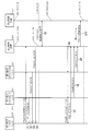
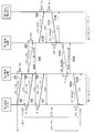
- 6 is a timing chart showing an operation when the first wireless device and the second wireless device are connected in the first to fourth embodiments.
- 6 is a timing chart showing an operation when the first wireless device and the second wireless device are connected in the first to fourth embodiments.
- 6 is a timing chart showing an operation when the first wireless device and the second wireless device are connected in the first to fourth embodiments.
- 6 is a timing chart showing an operation when the first wireless device and the second wireless device are connected in the first to fourth embodiments.
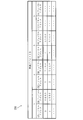
- FIG. 6 is a schematic diagram showing a PDP recognition list in the first to fourth embodiments.
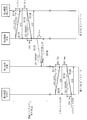
- 3 is a timing chart showing an operation at the time of transmission / reception of a CEC Give command in the first embodiment. It is a timing chart which shows the operation
- wireless apparatus in the said 3rd Embodiment. 12 is a timing chart showing the operation of the first and second radio apparatuses when CEC frame data is transmitted and received in the third embodiment. It is a timing chart which shows operation
- Data processing device and first wireless device as computing means 201 ...
- Report command substitution processing unit 206B as a reply response substitution processing unit 206B ...
- First dummy command transmission unit 230 as a first command transmission unit 230 ...
- Second wireless device 400C as data transfer device and second wireless device 406, 406B as calculation means Second ACK response substitution execution unit 407C that also functions as data transfer unit Second dummy command as second command transmission unit Transmission unit 500, 510, 520, 530 ... second device 900 ... CEC frame data as processing data 910 ... header block as divided data 920 ... data block as divided data
- HDMI High-Definition Multimedia Interface
- FIG. 1 is a schematic diagram showing a configuration of logical address setting information.
- the logical address setting information 800 includes address information 810 indicating a logical address represented by numbers 0 to 15 and device information 820 indicating a device to which the logical address of the address information 810 is set. It is equipped with.
- each device acquires a logical address that is predetermined for each function. Also, each device preferentially acquires the logical address having the smallest value among the logical addresses that can be acquired and that other devices have not acquired.
- FIG. 2 is a schematic diagram showing CEC frame data.
- CEC frame data 900 as processing data includes a header block 910 and 0 to 15 variable-length data blocks 920.
- the header block 910 includes a transmission-side logical address area 911, a reception-side logical address area 912, an EOM (End Of Message) area 913, and an ACK area 914.
- a logical address is recorded as first device information for identifying the device that is the transmission source of the CEC frame data 900.
- a logical address is recorded as second device information for identifying a transmission destination device of the CEC frame data 900.
- the header block 910 is recorded as CEC frame data 900.
- the ACK area 914 is used for ACK response processing indicating that the header block 910 has been received.
- the ACK response process when the transmitting device transmits the CEC frame data 900, the ACK area 914 is set to high impedance for a predetermined period, and when the receiving device receives the CEC frame data 900, the ACK response process is set to low for a predetermined period. It is a process to fix.
- the sending device recognizes that the receiving device has received (ACK response) if it is low, and recognizes that the receiving device has not received if it is high ( NACK response).
- the data block 920 includes a command area 921, an EOM area 922, and an ACK area 923.
- the command area 921 information related to commands for each device is recorded.
- the EOM area 922 and the ACK area 923 the same contents as the EOM area 913 and the ACK area 914 are recorded and processed.
- a command that requires a response is referred to as a “CEC Give command”.
- FIG. 3 is a schematic diagram showing a schematic configuration of the HDMI system.
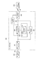
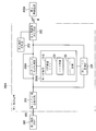
- FIG. 4 is a block diagram illustrating a schematic configuration of the first radio apparatus.
- FIG. 5 is a schematic diagram showing a shared device list.
- FIG. 6 is a schematic diagram showing node information.
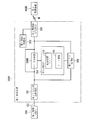
- FIG. 7 is a block diagram illustrating a schematic configuration of the second radio apparatus.
- the HDMI system 100 as a data processing system includes a first wireless device 200 as a data processing device and calculation means, first devices 300, 310, and 320, and a second wireless device as a data transfer device.
- the apparatus 400 and the 2nd apparatus 500,510,520,530 are provided.
- the first devices 300, 310, and 320 are a PDP (Plasma Display Panel), a first BDP (Blu-ray Disc Player), and a first DVDR (Digital Versatile Disc Recorder), respectively, and configure the first CEC network 101 together with the first wireless device 200. is doing.
- the second devices 500, 510, 520, and 530 are a first AVR (Audio Visual Receiver), a second BDP, a second DVDR, and a third DVDR, respectively, and constitute the second CEC network 102 together with the second wireless device 400. Also, the first device 300, 310, 320 and the second device 500, 510, 520, 530 perform a function for generating and transmitting CEC frame data 900, a function for ACK response to the CEC frame data 900, and processing for commands. And a function of returning a processing result for the CEC Give command as a CEC Report command.
- AVR Analog Visual Receiver
- examples of the CEC Report command include a command that returns a character or a physical address of an ASCII code indicating the manufacturer ID or product model name of the second device 500, 510, 520, or 530.
- each device is connected via a shared CEC signal line 103.
- each device is connected via a shared CEC signal line 103.
- the second wireless device 400 transmits and receives various data and information via the CEC signal line 103, Transmission / reception is performed after conversion to CEC frame data 900.
- the first device 300, 310, 320, the first wireless device 200, the second device 500, 510, 520, 530, and the second wireless device 400 transmit the CEC frame data 900 and do not receive an ACK response (NACK response). ), The same CEC frame data 900 is transmitted again. If it is recognized that an ACK response is not received (NACK response) even if the same CEC frame data 900 is transmitted a predetermined number of times, the CEC frame data 900 is discarded.
- CEC frame data 900 that is broadcast transmission that does not specify a destination device (when “15” UNREGISTERED / BRORDCAST is recorded in the reception-side logical address area 912 based on the logical address setting information 800), the received device Becomes a negative ACK response with a polarity opposite to that shown in the ACK response, and the transmitting device also has a negative ACK response to that effect and determines that the transmission was successful.
- the HDMI standard (Version 1.3a)
- the same device continuously transmits CEC frame data 900 having different contents, it is 16.8 msec (millisecond: hereinafter abbreviated as ms) or more.
- the new device transmits the CEC frame data 900, 12 ms or more. -7.2 ms or more when transmission of CEC frame data 900 fails and transmission is performed again.
- the first devices 300, 310, and 320 and the second devices 500, 510, 520, and 530 transmit and receive CEC frame data 900 based on this rule.
- the first device 300, 310, 320 and the second device 500, 510, 520, 530 return the Report command in response to the Give command
- the first device 300, 310, 320 may return within 200 ms after receiving the Give command. It is considered desirable, and here it is assumed to be 200 ms uniformly.
- the first device 300, 310, 320 and the second device 500, 510, 520, 530 recognize that there is no ACK response for a predetermined time or more after transmitting the CEC frame data 900, the same CEC frame data 900 is again transmitted. Send. If it is recognized that there is no ACK response even if the same CEC frame data 900 is transmitted up to five times, the CEC frame data 900 is discarded.
- the transmission destination is this command. It is determined that the command is ignored, and the transmission command related processing is stopped.
- the time count of 1000 ms starts from the time when the transmission destination recognizes the ACK response to the effect that the transmission destination has received the received Give command, and ends when the corresponding Report command is received.
- ⁇ Give Physical Address> is a response command ⁇ Give Physical Address>
- a character name for display is requested
- ⁇ Give OSD Name> if a character name for display is requested, ⁇ Give OSD Name>, The response command is ⁇ Set OSD Name>.
- the command length of the CEC frame data 900 also differs.
- ⁇ Give Physical Address> is 59.7 ms
- ⁇ Give Physical Address> is 142.2 ms
- ⁇ Give OSD Name> is 59.7 ms
- ⁇ Set OSD Name> is different depending on the number of characters. This is 444.7 ms which is the upper limit of the standard in the 900 configuration.
- the Give command and the Report command include a header block 910 and 15 data blocks 920 which are standard upper limit values in the configuration of the CEC frame data 900. It is assumed that the command length including the start sequence is uniformly 444.7 ms.
- LA represents a logical address set for each device
- PA represents a physical address set for each device.
- the first device (first BDP) 310 that is a playback device acquires a logical address of “4” based on the logical address setting information 800.
- the physical address of the first device 310 is set to “1.0.0.0”.
- the acquisition of the logical address of each device is only the header block 910 in which the logical address to be acquired is recorded in both the transmission-side logical address area 911 and the reception-side logical address area 912, and CEC frame data without the data block 920.
- the polling command constituted by 900 is transmitted on the first and second CEC networks 101 and 102 connected by the shared CEC signal line 103.
- the logical address is acquirable by the NACK response of each apparatus, and acquires it.
- it is referred to as a polling command (acquisition).
- acquisition in order for each device to grasp the device connected to the CEC network, its own logical address is recorded in the transmission-side logical address region 911, and the logical address to be confirmed for connection is recorded in the reception-side logical address region 912.
- the polling command composed of the CEC frame data 900 which has only the header block 910 and does not have the data block 920 is transmitted on the first and second CEC networks 101 and 102 connected by the shared CEC signal line 103. And it recognizes whether it exists by the ACK response of each apparatus, or a NACK response. Hereinafter, it is called a polling command (recognition).
- the first radio apparatus 200 is connected to the first CEC network 101 via the shared CEC signal line 103.
- the first wireless device 200 acquires various data and information such as CEC frame data 900 transmitted from the first device 300 or the like via the CEC signal line 103 and acquires the second wireless device via the wireless medium M. 400.
- CEC frame data 900 transmitted from the first device 300 or the like via the CEC signal line 103
- 30 ms is assumed.
- the first wireless device 200 acquires various data and information transmitted from the second wireless device 400 via the wireless medium M, and transmits them to the first device 300 and the like.
- wireless apparatus 200 is comprised from various programs, and as shown in FIG.
- the 1st CEC side transmission / reception part 201 as a data reception part
- wireless side transmission / reception part 202 as a data transmission part
- the first CEC side transmission / reception unit 201 is connected to the first device 300 via the shared CEC signal line 103.
- the first CEC side transmission / reception unit 201 converts the CEC frame data 900 from the first device 300 into various types of data, etc., to the first wireless side transmission / reception unit 202, the first list management unit 205, and the first ACK response substitution execution unit 206.
- Send various data from the first wireless-side transmitting / receiving unit 202, the first list management unit 205, and the first ACK response substitution execution unit 206 are converted into CEC frame data 900 and transmitted to the first device 300 and the like.
- the first wireless-side transceiver unit 202 transmits various data from the first connection processing unit 203, the first list management unit 205, and the first ACK response substitution execution unit 206 to the second wireless device 400 as wireless packets.
- the same wireless packet is transmitted again. This process is repeated a predetermined number of times until a wireless packet reception response is obtained.
- the wireless packet is discarded. Further, the wireless packet from the second wireless device 400 is converted into various data and transmitted to the first connection processing unit 203, the first list management unit 205, and the first ACK response substitution execution unit 206.
- the first connection processing unit 203 performs connection processing with the second wireless device 400.
- the first storage unit 204 stores a shared device list 210 as shown in FIG. 5 and node information 220 as shown in FIG.
- the shared device list 210 includes first logical address information 211 and second logical address information 212.
- first logical address information 211 first devices 300, 310, and 320 that can transmit and receive various data to and from the first wireless device 200, and their logical addresses are recorded.
- first BDP LA: 4 represents that the logical address of the first device 310 is 4.
- second devices 500, 510, 520, and 530 capable of transmitting and receiving various data to and from the second wireless device 200, and their logical addresses are recorded.
- the shared device list 210 has a configuration having only a logical address.
- the first and second devices 300 and 310 include a physical address, a manufacturing company ID, a product model name character, a device type, information on the CEC version, and the like. , 320, 500, 510, 520, 530 and the like may be associated with the logical address.
- the node information 220 has a structure capable of registering logical addresses and physical addresses of a plurality of devices for each wireless device ID. That is, for example, when the wireless device ID is 1, a device having a logical address of “0” and a physical address of “0.0.0.0” and a logical address of “1” and a physical address of “1. 1.0.0.0 "can be registered.
- the first list management unit 205 transmits and receives various data between the first wireless device 200 and the first devices 310 and 320 when the first wireless device 200 and the second wireless device 400 are connected so as to be able to transmit and receive various data.
- the shared device list 210 of the first storage unit 204 is appropriately created and Update. The detailed operation of the first list management unit 205 will be described later.
- the receiving side logical address area 912 of the header block 910 is obtained.
- the second devices 500, 510, 520, and 530 that are the transmission destinations of the CEC frame data 900 are recognized based on the logical address of. For example, when the second device 510 as a transmission destination is registered in the shared device list 210 and the CEC frame data 900 is not a Give command, the second device 510 receives the CEC frame data 900 based on the ACK generation signal. ACK response to the effect is executed.
- the second device 510 when the second device 510 as the transmission destination is registered in the shared device list 210 and the CEC frame data 900 is a Give command, the second device 510 has received the Give command without executing an ACK response. When ACK is recognized, an ACK response is executed. The detailed operation of the first ACK response substitution execution unit 206 will be described later.
- the second radio apparatus 400 is connected to the second network 102 via the shared CEC signal line 103, and acquires various data and information transmitted from the second device 500 via the CEC signal line 103. And transmitted to the first radio apparatus 200 via the radio medium M. Further, the second wireless device 400 acquires various data and information transmitted from the first wireless device 200 via the wireless medium M, and transmits the various data and information to the second device 500.
- the second radio apparatus 400 is composed of various programs. As shown in FIG.
- the second CEC side transceiver unit 401, the second radio side transceiver unit 402, the second connection processing unit 403, and the transfer A second storage unit 404 as a side storage unit, a second list management unit 405 that also functions as a second device information generation unit, and a second ACK response substitution execution unit 406 that also functions as a data transfer unit. .
- the second CEC side transmission / reception unit 401 is connected to the second device 500 via the shared CEC signal line 103.
- the second CEC side transmission / reception unit 401 converts the CEC frame data 900 from the second device 500 into various data and transmits the data to the second list management unit 405 and the second ACK response substitution execution unit 406.
- 8 ms is assumed as an example of processing time from reception to transmission.
- various data from the second list management unit 405 and the second ACK response substitution execution unit 406 are converted into CEC frame data 900 and transmitted to the second device 500. At this time, if an ACK response cannot be obtained for transmission of CEC frame data 900 other than broadcast transmission, the same CEC frame data 900 is transmitted again.
- This process is repeated a predetermined number of times until an ACK response is obtained.
- the CEC frame data 900 is discarded.
- the second radio-side transmitting / receiving unit 402 transmits various data from the second connection processing unit 403, the second list management unit 405, and the second ACK response substitution execution unit 406 to the first radio apparatus 200 as radio packets.
- the same wireless packet is transmitted again.
- This process is repeated a predetermined number of times until a wireless packet reception response is obtained. If the number exceeds this number, the wireless packet is discarded.
- the wireless packet from the first wireless device 200 is converted into various data and transmitted to the second connection processing unit 403, the second list management unit 405, and the second ACK response substitution execution unit 406.
- the second connection processing unit 403 performs connection processing with the first wireless device 200.
- the second storage unit 404 stores the same shared device list 210 and node information 220 as the first storage unit 204. Is remembered.
- the second list management unit 405 appropriately creates and updates the shared device list 210 in the second storage unit 404 at the same timing as the first list management unit 205. The detailed operation of the second list management unit 405 will be described later.
- the second ACK response substitution execution unit 406 performs the same process as the first ACK response substitution execution unit 206 of the first radio apparatus 200. The detailed operation of the second ACK response substitution execution unit 406 will be described later.
- FIG. 8 is a schematic diagram illustrating a connection state of each device and a logical address setting state before the connection between the first wireless device and the second wireless device.
- FIG. 9 is a schematic diagram illustrating a connection state and a logical address setting state of each device after connection between the first wireless device and the second wireless device.
- 10 to 12 are timing charts showing operations when the first radio apparatus and the second radio apparatus are connected.
- FIG. 13 is a schematic diagram showing a PDP recognition list. As shown in FIG. 8, the first wireless device 200 to which the first devices 300, 310, and 320 are connected and the second wireless device 400 to which the second devices 500, 510, 520, and 530 are connected are connected.
- the first BDP 310 and the first DVDR 320 are turned on, the first wireless device 200 is turned off, and DDC_5V is turned off ( In FIG. 10 and the like, this is represented as “DDC — 5V_OFF”).
- DDC — 5V_OFF When the power of the second wireless device 400 is off and the hot plug is high, when the power of the PDP 300 is switched from off to on, the PDP 300 has its own logical address. In order to recognize each device connected after acquiring “0”, the first wireless device 200, the first BDP 310, the first DV Polling command for R320 (recognition) performs processing (step S1).
- CEC frame data 900 composed of a header block 910 in which the logical address of the PDP 300 is recorded in the transmission-side logical address area 911 and any one of “1 to 14” is recorded in the reception-side logical address area 912.
- the polling command (recognition) process for the logical addresses “12” and “13” that are RESERVED may be omitted.
- the first BDP 310 receives the header block 910 in which the logical address “4” is recorded in the receiving logical address area 912
- the first BDP 310 performs an ACK response to that effect (step S2).
- the first DVDR 320 makes an ACK response indicating that the header block 910 in which the logical address “1” is recorded in the receiving-side logical address area 912 has been received (step S3).
- the first radio apparatus 200 makes a NACK response because the power is off (step S4).
- the first connection processing unit 203 starts the initial setting process to make it communicable via the wireless medium M as shown in FIG. 9, and as shown in FIG. 10, the second wireless device A connection establishment process is executed with 400 second connection processing units 403 (step S5).
- this connection establishment process for example, an HDMI repeater process such as a process of switching the hot plug of the second wireless device 400 from high to low and an EDID reading or rewriting process of the PDP 300 is performed. Due to the hot plug state change at this time, each of the second devices 500, 510, 520, and 530 discards its own logical address once acquired.
- the first list management unit 205 of the first wireless device 200 performs a polling command (recognition) process on the first CEC network 101 in order to recognize the connected device in the same manner as the process of step S1 in the PDP 300.
- step S6 In response to this polling command (recognition) process, the PDP 300, the first BDP 310, and the first DVDR 320 perform an ACK response indicating that the header block 910 in which the logical addresses “0”, “4”, and “1” are received is received. (Steps S7, S8, S9).
- the first list management unit 205 sets the logical addresses of the PDP 300, the first BDP 310, and the first DVDR 320 to “0”, “4”, and “1” when the ACK response is confirmed by the first CEC-side transmission / reception unit 201.
- the first logical address information 211 to that effect is generated and transmitted to the second list management unit 405 of the second radio apparatus 400 (step S10). That is, the first list management unit 205 of the first radio apparatus 200 performs the logical address recorded in the reception-side logical address region 912 of the header block 910 of the polling command (recognition) processing that is sequentially performed and the ACK region that is processed by the reception-side device.
- the first logical address information 211 is generated by associating the results of the 914 ACK response and the NACK response. At this time, the polling command (recognition) processing for the logical addresses “12” and “13” which are RESERVED may be omitted.
- the second radio apparatus 400 switches the hot plug from low to high.
- the first AVR 500 again sets the logical address to “5” for the second CEC network 102 and performs a polling command (acquisition) process to acquire its own logical address (step S11).
- Replies from the second devices 510, 520, and 530 are NACK responses indicating that the logical address is not “5”, although not shown here.
- the second ACK response substitution execution unit 406 of the second radio apparatus 400 has the logical address “5” based on the first logical address information 211 from the first list management unit 205 via the second CEC-side transmission / reception unit 401. And the NACK response is made (step S12).
- the first AVR 500 recognizes the NACK response from the second devices 510, 520, 530 and the second radio apparatus 400, the first AVR 500 maintains “5” as its logical address.
- the second BDP 510 sets the logical address to “4” for the second CEC network 102 and performs a polling command (acquisition) process in order to acquire its own logical address (step) S13).
- the second devices 500, 520, and 530 make a NACK response.
- the second ACK response substitution execution unit 406 recognizes that the logical address of the first BDP 310 is “4” based on the first logical address information 211 via the second CEC side transmission / reception unit 401, and receives an ACK response. (Step S14).
- the second BDP 510 serving as the playback device recognizes the ACK response from the second radio apparatus 400, it determines that the logical address “4” has already been acquired by another device. Then, based on the logical address setting information 800, in order to confirm whether or not “8” that can be set for the playback device can be acquired, the logical address is again set to the second CEC network 102.
- the polling command (acquisition) process is performed with “8” set (step S15). In response to this polling command (acquisition) process, the second devices 500, 520, and 530 make a NACK response.
- the second ACK response substitution execution unit 406 confirms that the first devices 310 and 320 having the logical address “8” do not exist based on the first logical address information 211 via the second CEC side transmission / reception unit 401. Recognize it and make a NACK response to that effect (step S16).
- the second BDP 510 recognizes the NACK response from the second devices 500, 520, and 530 and the second wireless device 400, the second BDP 510 acquires and maintains “8” as its own logical address as shown in FIG.
- the second DVDR 520 When the second DVDR 520 performs a polling command (acquisition) process for acquiring its own logical address (step S17), the NACK response from the second device 500, 510, 530 and the first DVDR 320 from the second wireless device 400 are obtained. ACK response indicating that is set to “1” is recognized (step S18). Thereafter, the second DVDR 520 as the recording device performs the polling command (acquisition) process again in order to confirm whether or not the “2” that can be set for the recording device can be acquired (step S19). . Then, the second DVDR 520 recognizes the NACK response from the second devices 500, 510, 530 and the second radio apparatus 400 (step S20), and acquires “2” as its own logical address as shown in FIG. And maintain.
- the third DVDR 530 When the third DVDR 530 performs a polling command (acquisition) process for acquiring its own logical address (step S21), the third DVDR 530 returns an ACK response indicating that the first DVDR 320 is set to “1”. Recognize (step S22). Next, when the third DVDR 530 performs a polling command (acquisition) process for confirming whether acquisition is possible for “2” (step S23), an ACK indicating that the second DVDR 520 is set to “2”. The response is recognized (step S24). Further, when the third DVDR 530 performs a polling command (acquisition) process for confirming whether “9” can be acquired (step S25), the third DVDR 530 receives information from the second devices 500, 510, 520, and the second radio apparatus 400.
- the second list management unit 405 sets the logical addresses of the first AVR 500, the second BDP 510, the second DVDR 520, and the third DVDR 530 to “5”, “8”, “2”, and “9” based on the above processing. Temporary second logical address information is generated. That is, when the second list management unit 405 of the second wireless device 400 receives the CEC frame data 900 transmitted from the device connected to the second CEC network 102, the second list management unit 405 stores the CEC frame data 900 in the transmission-side logical address area 911 of the header block 910.
- the logical address recorded and the logical address recorded in the receiving logical address area 912 are recognized.
- the receiving logical address area recorded in the transmitting logical address area 911 of the header block 910 is determined.
- the second list management unit 405 performs the process without performing the monitoring process. finish.
- the second radio apparatus 400 performs a polling command (recognition) process for generating the second logical address information 212 for the first AVR 500, the second BDP 510, the second DVDR 520, and the third DVDR 530 (step S27).
- the second list management unit 405 stores the logical addresses of “5”, “8”, “2”, and “9” from the first AVR 500, the second BDP 510, the second DVDR 520, and the third DVDR 530.
- the ACK response to the polling command (recognition) is recognized by the second CEC-side transmitting / receiving unit 401 (steps S28, S29, S30, S31), this result is collated with the temporary second logical address information.
- the shared device as shown in FIG. 5 has the temporary second logical address information as the second logical address information 212 and the first logical address information 211 from the first list management unit 205.
- a list 210 is generated and stored in the second storage unit 404. If they do not match at this time, step S28 is performed an appropriate number of times, the hot plug is held from high to low for an appropriate period, and then the processing from step S11 can be performed again.
- the second logical address information 212 may be based on the information obtained by the implementation. In some cases, the processing of “operation when logical addresses overlap between the first device and the second device” described later may be performed.
- the second list management unit 405 of the second radio apparatus 400 performs the logical address recorded in the reception-side logical address area 912 of the header block 910 of the polling command (recognition) processing sequentially performed, the ACK response of the ACK area 914, and the NACK.
- the second logical address information 212 may be generated in association with the response result.
- the second list management unit 405 transmits the shared device list 210 to the first list management unit 205 of the first wireless device 200 (step S32).
- the first list management unit 205 performs "5", "8", "" of each device connected to the second CEC network 102 with respect to the first CEC network 101.
- the polling command (acquisition) process of the header block 910 in which the logical addresses “2” and “9” are recorded may be notified.
- the first list management unit 205 receives at least one of the logical addresses “5”, “8”, “2”, and “9”, an ACK indicating that another device has already been acquired.
- the process may be performed again from the process of step S11. In some cases, the processing of “operation when logical addresses overlap between the first device and the second device” described later may be performed. Then, the first list management unit 205 is able to acquire the NACK response when all the NACK responses are recognized in the polling command (acquisition) processing of the logical addresses “5”, “8”, “2”, and “9”. recognize. Then, DDC_5V of the first radio apparatus 200 is turned off. The first list management unit 205 of the first wireless device 200 stores the shared device list 210 in the first storage unit 204. Furthermore, the first radio apparatus 200 turns on DDC_5V after an appropriate period has elapsed.
- the PDP 300 when the PDP 300 recognizes that the DDC_5V of the first radio apparatus 200 has been switched from OFF to ON, the PDP 300 sequentially performs a polling command (recognition) process on the first CEC network 101 in order to recognize the connected device. (Step S33). Then, the first BDP 310 and the first DVDR 320 make an ACK response indicating that the logical addresses are set to “4” and “1” (steps S34 and S35).
- the first ACK response substitution execution unit 206 of the first radio apparatus 200 receives the logical addresses of the second DVDR 520, the first AVR 500, the second BDP 510, and the third DVDR 530 based on the shared device list 210 via the first CEC-side transmission / reception unit 201.
- An ACK response indicating that “2”, “5”, “8”, or “9” is set is made (steps S36, S37, S38, and S39).
- the PDP 300 recognizes the first devices 310 and 320, the second devices 500, 510, 520, and 530 that can transmit the CEC frame data 900, and the logical addresses thereof.
- a PDP recognition list 301 as shown in FIG. 13 is generated and stored.
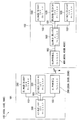
- FIG. 14 is a timing chart showing an operation during transmission / reception of the CEC Give command.
- the PDP 300 causes the sending logical address area 911 to have a logical address of “0” in order to cause the second BDP 510 in which the logical address is set to “8” to be executed. Is generated, and the CEC frame data 900 in which the logical address “8” is recorded in the reception-side logical address area 912 is generated. And as shown in FIG.
- this CEC frame data 900 is transmitted to the 1st radio
- the first radio apparatus 200 completes reception of all commands after 444.7 ms from transmission.
- the time required for transmission and reception of the Give command and the Report command is the same as 444.7 ms as described above, the description thereof will be omitted below.
- the first ACK response substitution execution unit 206 of the first wireless device 200 receives the second BDP 510 that has acquired the logical address of “8” based on the second logical address information 212 of the shared device list 210. It is determined whether or not the second radio apparatus 400 is connected. If it is determined that the PDP 300 is the transmission source, the first ACK response substitution execution unit 206 performs an ACK response process in the ACK area 914 in the header block 910 in the CEC frame data 900 for the transmission source PDP 300. If no information indicating that the current block is the last is recorded in the EOM area 922 in the data block 920, an ACK response process is performed in the ACK area 923, and the current block is the last in the EOM area 922.
- a NACK response indicating that the Give command has not been received is made in the ACK area 923 (step S62).
- the ACK response substitution execution unit 206 may perform a NACK response indicating that the Give command has not been received in all the ACK regions (ACK region 914 and ACK region 923) in the CEC frame data 900.
- the first ACK response substitution execution unit 206 transmits the Give command to the second radio apparatus 400 as a radio packet (step S63). As for this Give command, the second radio apparatus 400 completes reception of all commands 30 ms after transmission.
- the second ACK response substitution execution unit 406 of the second radio apparatus 400 transmits the Give command in which “8” is recorded in the reception-side logical address area 912 to the second BDP 510 (step S64).
- the second ACK response substitution execution unit 406 performs a wireless packet reception response to the first wireless device 200 indicating that reception of the Give command has been confirmed (step S65).
- the second BDP 510 that has received the Give command from the second radio apparatus 400 performs an ACK response indicating that it has been received (step S66).
- second radio apparatus 400 that has recognized the ACK response from second BDP 510 transmits a signal indicating that the ACK response has been recognized to first radio apparatus 200 (step S67).
- the PDP 300 that has recognized the NACK response in step S62 determines that the second BDP 510 has not received the Give command and determines that the second BDP 510 has received the Give command.
- Retry processing to retransmit up to once is started. That is, when the PDP 300 recognizes the NACK response in step S62, it retransmits the same Give command after 7.2 ms from this recognition according to the communication rule (step S68: retry 1). Since the first radio apparatus 200 has not yet recognized the ACK response from the second BDP 510 at the time of receiving this Give command, it makes a NACK response again (step S69). Then, the PDP 300 again transmits the same Give command (Step S70: Retry 2).
- the first ACK response substitution execution unit 206 of the first radio apparatus 200 receives the signal in step S67 during the reception of the Give command in step S70, the same Give command as that transmitted in step S61 is received originally. It is recognized that it has been received by the second BDP 510 that is the destination. Then, the first ACK response substitution execution unit 206 makes an ACK response indicating that the Give command has been received by the second BDP (step S71). Recognizing this ACK response, the PDP 300 starts a 1-second timer (not shown) and starts a process for confirming whether a Report command is returned within 1 second (1000 ms).
- the second BDP 510 starts processing corresponding to the Give command after making an ACK response in step S66, and transmits a Report command related to this processing to the second radio apparatus 400 (step S72).
- the process of step S72 is performed 200 ms after the process of step S66 (the time required for the process for the Give command in the second BDP 510).
- the second ACK response substitution execution unit 406 of the second radio apparatus 400 receives the Report command
- the second ACK response substitution execution unit 406 performs a logical address determination process in the same manner as in Step S62, and does not confirm reception of the Report command in the PDP 300, and thus returns a NACK response.
- the second ACK response substitution execution unit 406 transmits the Report command to the first radio apparatus 200 as a radio packet (step S74). In this Report command, the first radio apparatus 200 completes reception of all commands after 8 ms from transmission.
- the first radio apparatus 200 transfers the report command to the PDP 300 (step S75). Further, the first radio apparatus 200 sends a radio packet reception response to the second radio apparatus 400 indicating that reception of the Report command has been confirmed (step S76).
- the PDP 300 that has received the Report command from the first radio apparatus 200 stops the 1-second timer. At this time, since the time required from the receipt of the Give command at the first radio apparatus 200 to the reception of the corresponding Report command is 668.3 ms, which is less than 1 second, the PDP 300 has successfully executed the command by the second BDP 510. Judge. Then, the PDP 300 sends an ACK response indicating that the Report command has been received (step S77). The first radio apparatus 200 that has recognized the ACK response from the PDP 300 transmits a signal indicating that the ACK response has been recognized to the second radio apparatus 400 (step S78).
- the second BDP 510 that has recognized the NACK response in step S73 determines that the Report command has not been received by the PDP 300, and repeats the same Report command up to five times until it recognizes that the Report command has been received by the PDP 300. Retry processing to retransmit until is started. That is, when the second BDP 510 recognizes the NACK response in step S73, it retransmits the same Report command after 7.2 ms from this recognition according to the communication rule (step S79: retry 1). Since the second radio apparatus 400 has not yet recognized the ACK response from the PDP 300 when the Report command is received, the second radio apparatus 400 makes a NACK response again (step S80). Then, the second BDP 510 again transmits the same Report command (Step S81: Retry 2).
- the second radio apparatus 400 recognizes that the same Report command transmitted in Step S72 has been received by the PDP 300 that is the original receiving destination because the second wireless apparatus 400 has received the signal in Step S78 while receiving the Report command in Step S81. . Then, the second radio apparatus 400 makes an ACK response indicating that the Report command has been received by the PDP 300 (step S82).
- FIG. 15 is a timing chart showing an operation at the time of transmission / reception of the CEC Give command in the comparative example.
- the PDP transmits a Give command to the first wireless device (step S91).
- the first wireless device makes an ACK response indicating that the Give command has been received (step S92).
- the first wireless device transmits the Give command as a wireless packet to the second wireless device (step S93).
- the PDP that has recognized the ACK response in step S92 starts a one-second timer. If necessary, for example, as shown in steps S94 to S97, the PDP is ready to transmit a new Give command to the first wireless device after 16.8 ms in accordance with the communication rule.
- the second wireless device that has received the Give command in step S93 performs a wireless packet reception response indicating that the command has been received to the first wireless device (step S98), and transmits the Give command to the second BDP (step S98). S99).
- the second BDP receives the Give command
- the second BDP makes an ACK response (step S100), and further transmits a Report command to the second radio apparatus (step S101).
- the second wireless device receives the Report command, it sends an ACK response to that effect (step S102) and transmits this Report command to the first wireless device (step S103).
- the first wireless device that has received the Report command sets the wireless packet reception response to that effect to the second wireless device (step S104), and transmits this Report command to the PDP (step S105).
- the PDP stops the 1-second timer. At this time, since the required time from the receipt of the Give command at the first wireless device to the receipt of the Report command is 1572.1 ms, which exceeds 1 second, the PDP is It is determined that the command has not been executed, and processing related to the transmitted Give command has been stopped. Also, the PDP sends an ACK response indicating that the Report command has been received (step S106).
- the transmission destination of the CEC frame data 900 is the second wireless device 400 based on the contents of the reception-side logical address area 912. It is recognized as the second BDP 510 among a plurality of devices connected to.
- the second BDP 510 executes an ACK response to the effect that the CEC frame data 900 has been received to the PDP 300 instead of the second BDP 510, and transmits the CEC frame data 900 to the second BDP 510.
- the CEC frame data 900 is transmitted to the second BDP 510 without an ACK response, and the second BDP 510 transmits the CEC frame.
- the first radio apparatus 200 is compared with the comparative example in which the present invention is not applied, and the timing at which the PDP 300 starts the 1-second timer is the same as the original transmission destination as in the case where the CEC line is shared.
- the 2BDP 510 receives the data reliably, it is possible to accurately match.
- the second BDP 510 recognizes that it has received the Give command and starting the 1-second timer to when the corresponding Report command is received and when the 1-second timer is stopped, and a timeout occurs.
- the transmission processing from the first device 300, 310, 320 to the second device 500, 510, 520, 530 can be appropriately performed. Further, even in transmission processing from the second device 500, 510, 520, 530 to the first device 300, 310, 320, the first wireless device 200 and the second wireless device 400 perform the same operation, and thus the same. Can be implemented appropriately.
- the retry processing of the PDP 300 and the second BDP 510 causes the first and second CEC networks 101 and 102 to It is possible to suppress new command transmissions that are not irrelevant and to synchronize related commands. At the same time, it is possible to suppress a mismatch in the amount of communication traffic due to the separation of the CEC signal line 103.
- FIG. 16 is a block diagram illustrating a schematic configuration of the first radio apparatus.
- FIG. 17 is a block diagram illustrating a schematic configuration of the second radio apparatus.
- the HDMI system 100 ⁇ / b> A replaces the first wireless device 200 ⁇ / b> A as a data processing device and calculation means instead of the first wireless device 200 of the HDMI system 100, and a data transfer device instead of the second wireless device 400.
- the first radio apparatus 200A includes a first CEC-side transceiver unit 201, a first radio-side transceiver unit 202, a first connection processing unit 203, and a processing-side storage unit that are configured by various programs. And a first storage unit 204A as a reply response information storage unit, a first list management unit 205, and a report command substitution processing unit 206A as a reply response substitution processing unit.
- the first storage unit 204A stores a shared device list 210, node information 220, and report command information 230 as reply response information.
- the report command information 230 includes the content specifying the second device 500, 510, 520, 530 that is the destination of the predetermined Give command, the content of the Give command, and the second device 500, 510, 520, 530 The contents of the Report command corresponding to the Give command are recorded.
- the report command information 230 the logical address for specifying the second BDP 510 of the transmission destination, the content of the Give command requesting the transmission of the manufacturer ID and the product model name, and the manufacture of the second BDP 510 are included.
- the fact that the company is “Company A” and the product model name is “B-1” is recorded.
- report command information 230 may be stored in FIG. 16, only one report command information 230 is shown, but a plurality of report command information 230 may be stored. Further, the report command information 230 may further record the contents specifying the first device 300, 310, 320 that is the source of the give command. Further, a reply response information storage unit other than the first storage unit 204A may be provided in the first radio apparatus 200A, and the report command information 230 may be stored in the reply response information storage unit.
- the report command substitution processing unit 206A receives the give command and the information related to the second devices 500, 510, 520, and 530 transmitted from the second radio apparatus 400A, and the report command corresponding to the give command. Then, based on these various pieces of information, report command information 230 is generated and stored in the first storage unit 204A. Further, upon obtaining the CEC frame data 900 transmitted from the PDP 300, the report command substitution processing unit 206A recognizes the transmission destination of the CEC frame data 900. For example, when the second BDP 510 of the transmission destination is registered in the shared device list 210 and the CEC frame data 900 is not a Give command, the specific process is not performed, and the same process as the first ACK response substitution execution unit 206 is performed.
- the transmission destination is registered in the shared device list 210 and the CEC frame data 900 is a Give command
- the same processing as that of the first ACK response substitution execution unit 206 is performed and the transmission destination and the Give command are supported It is determined whether the report command information 230 to be stored is stored in the first storage unit 204A.
- the process equivalent to the first ACK response substitution execution unit 206 is a process of making an ACK response to the effect that the second BDP 510 as the original transmission destination has received the Give command.
- the report command substitution processing unit 206A determines that the report command is stored, the report command substitution processing unit 206A transmits the contents of the Report command recorded in the report command information 230 to the PDP 300 instead of the second BDP 510 of the transmission destination.
- the Give command is transmitted to the second BDP 510 via the radio-side transceiver unit 202.
- the Report command recorded in the report command information 230 is transmitted to the second BDP 510 without transmitting the Report command to the PDP 300.
- the second radio apparatus 400A has a configuration in which a report command pre-acquisition unit 407A configured from various programs is provided in the second radio apparatus 400.
- the report command pre-acquisition unit 407A independently generates the Give command before transmitting the Give command from the first device 300, 310, 320 and transmits it to all of the second devices 500, 510, 520, 530.
- a Report command is acquired in advance.
- the Give command, the information specifying the second devices 500, 510, 520, and 530, and the Report command are transmitted to the first radio apparatus 200A.
- the Report command may be acquired in advance for only one of the second devices 500, 510, 520, and 530.
- the Report command acquired in advance may be related to all the Give commands transmitted / received in the HDMI system 100A, or may be related to a part of the Give commands. Further, the report command pre-acquisition unit 407A generates report command information 230 that associates the contents of the Give command, information for specifying the second devices 500, 510, 520, and 530 and the contents of the Report command, You may transmit to the 1st radio
- FIG. 18 is a timing chart showing an operation during transmission / reception of the CEC Give command.
- the second radio apparatus 400A transmits a main Give command to all the second devices 500, 510, 520, and 530 (step S111).
- the second devices 500, 510, 520, and 530 that have received the Give command each send an ACK response (step S112).
- the second devices 500, 510, 520, and 530 perform processing for the Give command and transmit the Report command to the second wireless device 400A (step S113).
- the second radio apparatus 400A that has received the Report command sends an ACK response indicating that this has been received (step S114). Further, the Report command is transmitted to the first radio apparatus 200A together with the Give command and information specifying the second devices 500, 510, 520, and 530 (step S115).
- the first radio apparatus 200A that has received the Report command or the like makes a radio packet reception response to the effect that it has been received to the second radio apparatus 400A (step S116). Furthermore, the first radio apparatus 200A stores report command information 230 based on the received various information in the first storage unit 204A.
- the above is the pre-processing of the wireless system composed of the first and second wireless devices 200A and 400A.
- the PDP 300 transmits a predetermined Give command to the first radio apparatus 200A (Step S117).
- the first radio apparatus 200A that has received the Give command sends an ACK response to the effect that the transmission destination has received this Give command (step S118).
- first radio apparatus 200A determines whether or not report command information 230 corresponding to the give command and the transmission destination is stored in first storage unit 204A.
- a Report command 230 is transmitted to the PDP 300 (step S119).
- the Give command may be transmitted to the second device 500, 510, 520, 530 or the like as the transmission destination via the second wireless device 400A.
- the data is transmitted to the second devices 500, 510, 520, 530 and the like as the transmission destination via the second wireless device 400A.
- the PDP 300 makes an ACK response and stops the 1-second timer (step S120).
- the second wireless device 400A of the HDMI system 100A sends a predetermined Give command to all of the second devices 500, 510, 520, and 530 before the Give command is transmitted from the first devices 300, 310, and 320. Send to get Report command. Then, the Give command, the information specifying the second devices 500, 510, 520, and 530, and the Report command are transmitted to the first radio apparatus 200A.
- wireless apparatuses memorize
- the first wireless device 200A indicates that the transmission destination has received the Give command.
- An ACK response is performed instead of the transmission destination, and a Report command of the report command information 230 is transmitted to the PDP 300.
- the first radio apparatus 200A can make the time from when the PDP 300 starts the 1-second timer to when it stops being the same as when the CEC line is shared, so that a timeout occurs. Can be suppressed, and an appropriate Report command for the Give command can be transmitted to the PDP 300.
- transmission processing from the first device 300, 310, 320 to the second device 500, 510, 520, 530 can be appropriately performed. Further, even in the transmission processing from the second device 500, 510, 520, 530 to the first device 300, 310, 320, the first wireless device 200A and the second wireless device 400A perform the same operation, It can be implemented appropriately as well.
- the Report command is processed in the same processing time as when the CEC line is shared according to the present invention. Therefore, it is possible to suppress new command transmissions that are not originally related in the first and second CEC networks 101 and 102, and to synchronize related commands. At the same time, it is possible to suppress a mismatch in the amount of communication traffic due to the separation of the CEC signal line 103.
- FIG. 19 is a block diagram illustrating a schematic configuration of the first radio apparatus.
- the HDMI system 100 ⁇ / b> B replaces the first wireless device 200 ⁇ / b> B as a data processing device and calculation means instead of the first wireless device 200 of the HDMI system 100 with a data transfer device instead of the second wireless device 400.
- the first radio apparatus 200B includes a first CEC-side transceiver unit 201, a first radio-side transceiver unit 202, a first connection processing unit 203, and a first storage unit, which are composed of various programs. 204, a first list management unit 205, and a data division unit 206B.
- the data dividing unit 206B divides the CEC frame data 900 for each block. That is, the data is divided into a header block 910 as divided data and a data block 920 as divided data. For example, if the CEC frame data 900 includes five data blocks 920, the data is divided into five data blocks 920. Then, the data dividing unit 206B converts the divided header block 910 and data block 920 into individual wireless packets and transmits them to the second wireless device 400B. In this transmission, the header block 910 is transmitted first, and then the data block 920 is transmitted in the order in which the position in the data structure before division is close to the header block 910.
- the second radio apparatus 400B has a second ACK response substitution execution unit that also functions as a data transfer unit composed of various programs instead of the second ACK response substitution execution unit 406 of the second radio apparatus 400. It has a configuration provided with 406B.
- the second ACK response substitution execution unit 406B receives the header block 910 and the data block 920 divided from the first radio apparatus 200B, the second ACK response substitution execution unit 406B reproduces them as they are in the received order in the CEC frame data 900 and transmits the second device as the transmission destination. Transfer to 500, 510, 520, 530.
- FIG. 20 is a timing chart showing the operation of the first and second radio apparatuses during transmission / reception of CEC frame data.
- FIG. 21 is a timing chart showing the operation of the HDMI system at the time of transmission / reception of the CEC Give command as an embodiment when the above method is used.
- the first radio apparatus 200B receives CEC frame data 900 from, for example, the PDP 300. Specifically, at time T0, first radio apparatus 200B starts receiving header block 910 of CEC frame data 900.
- the first wireless device 200B recognizes the destination logical address based on the second logical address information 212 of the shared device list 210, and is connected. If it is determined that the ACK response process is performed in the ACK area 914 in the header block 910 in the CEC frame data 900, the header block 910 is divided from the CEC frame data 900. The wireless packet 941 is transmitted to the second wireless device 400B. Also, at time T1, the first radio apparatus 200B starts receiving the first data block 920. At this time, the ACK response processing in the ACK area 923 in the data block 920 is also performed in the same manner as the header block 910.
- the second wireless device 400B when receiving the wireless packet 941 at time T2, the second wireless device 400B returns the wireless packet 941 to the header block 910. Then, at time T2, the second radio apparatus 400B configures this header block 910 as the CEC frame data configuration and starts transmission to the second BDP 510, for example.
- the first wireless device 200B divides the data block 920 from the CEC frame data 900 to form a wireless packet 942. Send to 400B. Also, at time T3, the first radio apparatus 200B starts receiving a third header block 910 (not shown). Further, at time T3, the second radio apparatus 400B receives the radio packet 942 and returns it to the first data block 920. Then, at time T4, the second radio apparatus 400B starts transmission of the data block 920 to the second BDP 510.
- the first wireless device 200B transmits the wireless packet 943 to the second wireless device 400B.
- the second radio apparatus 400B receives the radio packet 943 and returns it to the Nth data block 920.
- the second radio apparatus 400B starts transmitting the data block 920 to the second BDP 510.
- the same wireless packet may be transmitted a plurality of times in order to increase the reliability of transmission.
- An error correction technique such as an encoding / decoding technique may be used.
- the header block 910, the order of blocks of each data block 920, the number of blocks, and the like may be transmitted by adding information that can be clearly recognized on the second radio apparatus 400B side.
- the transmission timing from the second wireless device 400B to the transmission destination device, eg, the second BDP 510, indicates that information indicating that the current block of the EOM areas 913 and 923 in the CEC frame data 900 is the last is recorded. You may start with the 2nd radio
- the block to be transmitted in a divided manner is not limited to one block unit in the configuration of the CEC frame data 900 such as the header block 910 and each data block 920.
- this block is a unit of several blocks, 1 bit, or several Radio packets may be transmitted in units of bits.
- the time for transmitting the header block 910 from the first device (PDP) 300 to the first radio apparatus 200B is defined as the first time.
- the time for transmitting the first data block 920 to the radio apparatus 200B that is, the time from the time T1 to the time T3 is set as the second time.
- the time for transmitting the wireless data packet 941 corresponding to the header block 910 from the first wireless device 200B to the second wireless device 400B is set as the third time, and similarly, the first wireless device 200B.
- the time for transmitting the wireless data packet 942 corresponding to the first data block 920 to the second wireless apparatus 400B from the time T3 to the time T4 is defined as the fourth time.
- the third time is shorter than the corresponding first time.
- the fourth time is shorter than the corresponding second time.
- the time for transmitting the header block 910 from the second radio apparatus 400B to the second device (second BDP) 510, that is, the time from the time T2 to the time T4 is equal to the first time.
- the time for transmitting the first data block 920 from the second radio apparatus 400B to the second device 510 is equal to the second time.
- the time for transmitting the header data block 910 and each data block 920 from the first device 300 to the first radio apparatus 200B is equal to the second time, and the first radio apparatus 200B to the second radio apparatus 400B.
- the time for transmitting the header data block 910 and the wireless data packet corresponding to each data block 920 is equal to the fourth time, and the header data block 910 and each data block 920 are transmitted from the second wireless device 400B to the second device 510.
- the transmission time is equal to the second time. In this way, the sum of the time for dividing the CEC frame data 900 into a plurality of wireless data packets and transmitting from the first wireless device 200B to the second wireless device 400B is shorter than the transmission time of the CEC frame data 900. To do.
- the transmission speed of each wireless data packet is set so that the transmission time of each wireless data packet is shorter than the transmission time of a part of CEC frame data 900 corresponding to the wireless data packet.
- the original CEC frame data 900 can be reproduced from the plurality of wireless data packets by the second wireless device 400B.
- the communication delay time generated between the first radio apparatus 200B and the second radio apparatus 400B can be made a transmission time of a part of the CEC frame data 900 corresponding to one radio data packet. .
- the PDP 300 transmits CEC frame data 900 related to the Give command to the first radio apparatus 200B (step S131).
- the first radio apparatus 200B performs an ACK response process in the ACK area 914 in the header block 910 and divides the header block 910 from the CEC frame data 900.
- transmission to the second radio apparatus 400B is started 27.5ms after the start of the transmission process in step S131 (equivalent to the block length of the header block 910) (step S132).
- the first radio apparatus 200B performs the ACK response process in the ACK area 923 in the data block 920 and the data block 920 obtained by dividing the second radio block 200B.
- the data is sequentially transmitted to the device 400B.
- the ACK area of the final block indicating that the entire CEC frame data 900 has been received (a block in which information indicating that the current block is the last is recorded in the EOM area 922)
- An ACK response of 923 is made (step S133). Recognizing the ACK response, the PDP 300 starts a one-second timer.
- the second radio apparatus 400B starts transmission to the second BDP 510 30 ms after the start of transmission in step S132 (step S134), and reception in units of data blocks 920 is performed. Is completed, the data block 920 is sequentially transmitted to the second BDP 510.
- a wireless packet reception response to that effect is sent to the first wireless device 200B (step S135).
- the second BDP 510 sequentially performs ACK response processing in the ACK areas 914 and 923 from the start of transmission in step S134, and after receiving all the divided data after 444.7 ms, the second BDP 510 sends an ACK response in the ACK area 923 of the final block.
- step S136 the CEC frame data 900 of the Report command for the Give command is transmitted to the second radio apparatus 400B (step S137).
- the second radio apparatus 400B starts transmission to the first radio apparatus 200B after 27.5 ms from the transmission start of step S137, together with the ACK response processing in the ACK area 914 (step S138).
- the data blocks 920 are sequentially transmitted to the first radio apparatus 200B together with the ACK response processing in the ACK area 923.
- an ACK response is sent to the ACK area 923 of the last block (step S139).
- the first radio apparatus 200B starts transmission to the PDP 300 after 8 ms from the start of transmission in step S138 (step S140), and every time reception in units of data blocks 920 is completed.
- the data blocks 920 are sequentially transmitted to the PDP 300.
- the 1 second timer is stopped.
- the PDP 300 has successfully executed the command by the second BDP 510.
- the PDP 300 makes an ACK response (step S141).
- the first radio apparatus 200B that has recognized the ACK response from the PDP 300 performs a radio packet reception response indicating that the ACK response has been recognized to the second radio apparatus 400B (step S142).
- FIG. 22 is a timing chart showing the operation of the first and second radio apparatuses during transmission / reception of CEC frame data in the comparative example.
- the first radio apparatus starts receiving the header block 910 of the CEC frame data 900 at time T0.
- the entire CEC frame data 900 is not divided and transmitted as one wireless packet 961 to the second wireless device.
- the second wireless device completes reception of the wireless packet 961, returns it to the CEC frame data 900, and transmits it to the second BDP.
- the second wireless device transmits to the second devices 500, 510, 520, and 530.
- the time required to start the transfer of the header block 910 (hereinafter referred to as transfer start required time) is a time between time T0 and time T6 and depends on the data amount of the CEC frame data 900.
- the transfer start required time is the time between the time T0 and the time T2, and is constant regardless of the data amount of the CEC frame data 900. I know that there is.
- the first wireless device 200B of the HDMI system 100B divides the CEC frame data 900 into a header block 910 and a data block 920. Then, the wireless packet is individually transmitted to the second wireless device 400B. Each time the second wireless device 400B receives wireless packets from the first wireless device 200B, the second wireless device 400B reproduces the CEC frame data 900 in the order in which they are received and transfers them to the second BDP 510, for example. For this reason, the HDMI system 100B can shorten the transfer start time as compared with the comparative example to which the present invention is not applied, and is constant and fast with respect to the second BDP 510 of the transmission destination without depending on the data amount of the CEC frame data 900.
- All the CEC frame data 900 can be received at the timing. Therefore, since all the CEC frame data 900 can be received by the PDP 300 at a timing earlier than that of the comparative example, it is possible to shorten the time until the 1-second timer is stopped, to suppress the occurrence of a timeout, and to The transmission / reception response in communication can be improved. Therefore, transmission processing from the first device 300, 310, 320 to the second device 500, 510, 520, 530 can be appropriately performed. Further, even in the transmission processing from the second device 500, 510, 520, 530 to the first device 300, 310, 320, the first wireless device 200B and the second wireless device 400B perform the same operation, It can be implemented appropriately as well.
- FIG. 23 is a block diagram illustrating a schematic configuration of the first radio apparatus.
- FIG. 24 is a block diagram illustrating a schematic configuration of the second radio apparatus.
- the HDMI system 100 ⁇ / b> C replaces the first wireless device 200 ⁇ / b> C as a data processing device and calculation means instead of the first wireless device 200 of the HDMI system 100 with a data transfer device instead of the second wireless device 400.
- the second wireless device 400C as a calculation unit is provided.
- the first radio apparatus 200C includes a first CEC side transmission / reception unit 201, a first radio side transmission / reception unit 202, a first connection processing unit 203, and a first storage unit, which are configured by various programs. 204, a first list management unit 205, a first ACK response substitution execution unit 206, and a first dummy command transmission unit 207C as a first command transmission unit.
- the first dummy command transmission unit 207C recognizes that the first ACK response substitution execution unit 206 has received an ACK response instead of the second BDP 510 when receiving a Give command with the second BDP 510 as a transmission destination, for example, A dummy command is transmitted to all the first devices 310 and 320 connected to the PDP 300 (to the first CEC network 101). Further, each time an ACK response or NACK response to the dummy command is recognized, the dummy command is transmitted again to all the first devices 300, 310, and 320. Then, when the first dummy command transmission unit 207C recognizes that the Report command for the Give command has been received by the first wireless side transmission / reception unit 202, the transmission of the dummy command is terminated.
- the dummy commands transmitted by the first dummy command transmission unit 207C and the second dummy command transmission unit 407C described later are as follows. That is, a polling command, which is considered to be relatively free from problems in CEC communication on the CEC network, is transmitted to the CEC network connected by the shared CEC signal line, and exists by the ACK response and NACK response of each device. It is a command that recognizes whether or not Here, the polling command is for each device to grasp the device connected to the CEC network, and its own logical address is recorded in the transmission-side logical address region 911, and the reception-side logical address region.
- the dummy command is not limited to the above, and any dummy command may be used as long as no problem occurs in CEC communication on the CEC network.
- the second radio apparatus 400C includes a second CEC-side transceiver unit 401, a second radio-side transceiver unit 402, a second connection processing unit 403, and a second storage unit, which are composed of various programs. 404, a second list management unit 405, a second ACK response substitution execution unit 406, and a second dummy command transmission unit 407C as a second command transmission unit. If the second dummy command transmission unit 407C recognizes that an ACK response has been received instead of the PDP 300 when the second ACK response substitution execution unit 406 receives a report command with the PDP 300 as a transmission destination, for example, the second dummy command transmission unit 407C includes the transmission source of the report command.
- a dummy command is transmitted to all the second devices 510, 520, and 530 connected to the first AVR 500 (to the second CEC network 102). Further, every time an ACK response or NACK response to the dummy command is recognized, the dummy command is transmitted again to all the second devices 500, 510, 520, and 530. Then, when the second dummy command transmission unit 407C recognizes that the Report command has been received at the transmission source of the Give command, the transmission of the dummy command is terminated.
- FIG. 25 is a timing chart showing an operation during transmission / reception of the CEC Give command.
- the PDP 300 transmits a Give command for the second BDP 510 to the first radio apparatus 200C (step S161).
- the first ACK response substitution executing unit 206 of the first radio apparatus 200C makes an ACK response to that effect (step S162).
- the PDP 300 recognizes the ACK response, the PDP 300 starts a 1-second timer.
- the first radio apparatus 200C transmits a Give command to the second radio apparatus 400C (step S163).
- the first dummy command transmission unit 207C of the first radio apparatus 200C transmits the dummy command to all the first devices 300, 310, and 320 until the Report command is received by the first radio-side transmission / reception unit 202.
- the ACK response or NACK response process (step S164) for the dummy command is repeated.
- the first devices 300, 310, and 320 cannot newly transmit a Give command to the first radio apparatus 200C, for example.
- the second radio apparatus 400C that has received the Give command sends a radio packet reception response to that effect to the first radio apparatus 200C (step S165). Further, the Give command is transmitted to the second BDP 510 (step S166).
- the second wireless device 400C recognizes an ACK response from the second BDP 510 that has received the Give command (step S167)
- the second BDP 510 transmits a signal to the first wireless device 200C that the second BDP 510 has received the Give command (step S167). S168).
- the second BDP 510 generates a Report command for the Give command and transmits it to the second radio apparatus 400C (step S169).
- the second wireless device 400C transmits an ACK response (Step S170) and transmits the Report command to the first wireless device 200C (Step S171). Then, when the transmission process of the Report command is performed, the second dummy command transmission unit 407C of the second wireless device 400C performs all the second devices 500 and 510 until it recognizes that the Report command has been received by the PDP 300. , 520, and 530, a dummy command is transmitted, and an ACK response or NACK response process (step S172) for the dummy command is repeated. By performing the process of step S172, the second devices 500, 510, 520, and 530 cannot transmit a new Give command to the second radio apparatus 400C, for example.
- the first radio apparatus 200C when the first radio apparatus 200C receives the Report command by the first radio side transmitting / receiving unit 202, the first radio apparatus 200C sends a radio packet reception response to that effect to the second radio apparatus 400C (step S173). Further, the first dummy command transmission unit 207C ends the dummy command transmission process because the Report command is received by the first wireless-side transmission / reception unit 202. In addition, the first radio apparatus 200C transmits a Report command to the PDP 300 (step S174). Thereafter, when the PDP 300 receives the Report command, the PDP 300 stops the one-second timer and makes an ACK response (step S175).
- first radio apparatus 200C transmits a signal indicating that the ACK response has been recognized to second radio apparatus 400C (step S176).
- the second dummy command transmission unit 407C of the second wireless device 400C recognizes the signal indicating that the ACK response has been recognized from the first wireless device 200C, it determines that the Report command has been received by the PDP 300, and transmits the dummy command. Exit.
- the second devices 500, 510, 520, and 530 can freely transmit, for example, a Give command if necessary according to the communication start rule when no other device is communicating. it can.
- the first wireless device 200C of the HDMI system 100C makes an ACK response. Then, the first radio apparatus 200C transmits a Give command to the second BDP 510 and transmits a dummy command to all the first devices 300, 310, and 320. For this reason, the first radio apparatus 200C causes all the first devices 300, 310, and 320 to perform the process for the dummy command after sending the Give command until the Report command is returned. For example, it is possible to restrict the first devices 300, 310, and 320 from transmitting a new Give command.
- a Report command is returned, for example, a new Give command as shown in step S94 to step S97 is transmitted to the second radio apparatus 400C, thereby suppressing a new command transmission that is not originally related. And a series of related command actions can be synchronized. Further, it is possible to suppress a mismatch in communication traffic volume due to the separation of the CEC signal line 103 between the first and second CEC networks 101 and 102.
- the first radio apparatus 200C ends the transmission of the dummy command and makes the first devices 300, 310, and 320 ready to transmit and receive various data. For this reason, the Report command can be quickly transmitted to the PDP 300 that is the transmission source of the Give command.
- the second wireless device 400C of the HDMI system 100C transmits this Report command to the first wireless device 200C, and dummy for all the second devices 500, 510, 520, and 530. Send command. For this reason, the second wireless device 400C causes all the second devices 500, 510, 520, and 530 to perform the process for the dummy command after transmitting the Report command, so that the second devices 500, 510, 520, and 530 are performed. For example, transmission of a new Give command can be restricted. Therefore, by the time a Report command is received by the PDP 300 until it is recognized, for example, a new Give command as shown in step S94 to step S97 is transmitted to the first radio apparatus 200C, which is irrelevant.
- New command transmissions can be suppressed, and a series of related command actions can be synchronized. Further, it is possible to suppress a mismatch in communication traffic volume due to the separation of the CEC signal line 103 between the first and second CEC networks 101 and 102.
- the second wireless device 400C recognizes that the Report command has been received by the PDP 300, the second wireless device 400C ends the transmission of the dummy command, and the second devices 500, 510, 520, and 530 can transmit and receive various data. To. For this reason, it is possible to cause the second devices 500, 510, 520, and 530 to quickly perform transmission processing of a new Give command.
- the first CEC network 101 may be configured by only the PDP 300
- the second CEC network 102 may be configured by only one of the second BDP 510, the second DVDR 520, and the third DVDR 530.
- the number of transmissions of the dummy command by the first and second radio apparatuses 200C and 400C may be performed a preset number of times.
- the connected devices of the first and second CEC networks 101 and 102 may be connected to the above embodiment or more.
- the number of wired medium connection connectors for the first CEC-side transmitting / receiving unit 201 and the second CEC-side transmitting / receiving unit 401 connected to the CEC signal line 103 is not limited to one, and there are a plurality. It is good also as a structure.
- the first wireless device 200 and the second wireless device 400 may have a plurality of HDMI connectors. The action and effect may be improved by combining a plurality of processes shown in the first to fourth embodiments.
- the information to be replaced is not limited to the logical address, but may be applied to information specific to each connected device, such as a physical address.
- a wired medium such as an optical fiber or an HDMI cable may be applied to transmission / reception of various data between the first wireless device 200 and the second wireless device 400.
- each function described above is constructed as a program, but it may be configured by hardware such as a circuit board or an element such as one IC (Integrated Circuit), and can be used in any form.
- IC Integrated Circuit
- the first radio apparatus 200 when the first radio apparatus 200 recognizes from the PDP 300 that the CEC frame data 900 does not include the Give command, the first radio apparatus 200 transmits an ACK response to the effect that the second BDP 510 has received the CEC frame data 900. This is executed for the PDP 300 instead of the second BDP 510, and the CEC frame data 900 is transmitted to the second BDP 510. Further, when recognizing that the CEC frame data 900 includes the Give command, the CEC frame data 900 is transmitted to the second BDP 510 with an ACK response.
- the first radio apparatus 200 has the second BDP 510 that is the original transmission destination as in the case where the timing CEC line for starting the 1-second timer is shared by the PDP 300. It is possible to accurately match when it is received reliably.
- the time from when the second BDP 510 recognizes that it has received the Give command and starting the 1-second timer to when the corresponding Report command is received and when the timer is stopped can be shortened, and the occurrence of a timeout can be suppressed.
- the transmission processing from the first device 300, 310, 320 to the second device 500, 510, 520, 530 can be appropriately performed. Further, even in transmission processing from the second device 500, 510, 520, 530 to the first device 300, 310, 320, the first wireless device 200 and the second wireless device 400 perform the same operation, and thus the same. Can be implemented appropriately.
- the retry processing of the PDP 300 and the second BDP 510 causes the first and second CEC networks 101 and 102 to It is possible to suppress new command transmissions that are not irrelevant and to synchronize related commands. At the same time, it is possible to suppress a mismatch in the amount of communication traffic due to the separation of the CEC signal line 103.
- the first wireless device 200A causes the first storage unit 204A to store report command information 230 based on various types of information transmitted from the second wireless device 400A. Then, when the Report command 230 of the Give command received from the PDP 300 and the report command information 230 regarding the transmission destination are stored in the first storage unit 204A, an ACK response indicating that the transmission destination has received the Give command is sent instead of the transmission destination. At the same time, a Report command of the report command information 230 is transmitted to the PDP 300. For this reason, the first radio apparatus 200A can make the time from when the PDP 300 starts the 1-second timer to when it stops being the same as when the CEC line is shared, so that a timeout occurs.
- the first wireless device 200B of the HDMI system 100B when the first wireless device 200B of the HDMI system 100B receives the Give command from the PDP 300, the first wireless device 200B divides the CEC frame data 900 into a header block 910 and a data block 920, and individually transmits the wireless packet. To the second radio apparatus 400B. Each time the second wireless device 400B receives wireless packets from the first wireless device 200B, the second wireless device 400B reproduces them as CEC frame data 900 in the order in which they are received, and transfers them to the second BDP 510.
- the HDMI system 100B can shorten the transfer start time as compared with the comparative example to which the present invention is not applied, and the constant early timing without depending on the data amount of the CEC frame data 900 with respect to the second BDP 510 of the transmission destination.
- all the CEC frame data 900 can be received. Therefore, since all the CEC frame data 900 can be received by the PDP 300 at a timing earlier than that of the comparative example, it is possible to shorten the time until the 1-second timer is stopped, to suppress the occurrence of a timeout, and to The transmission / reception response in communication can be improved. Therefore, transmission processing from the first device 300, 310, 320 to the second device 500, 510, 520, 530 can be appropriately performed.
- the first wireless device 200B and the second wireless device 400B perform the same operation, It can be implemented appropriately as well.
- the CEC line is shared according to the present invention. Therefore, it is possible to suppress new command transmissions that are not originally related to the first and second CEC networks 101 and 102, to synchronize related commands, and to minimize degradation of transmission and reception responses. Can do. At the same time, it is possible to suppress a mismatch in the amount of communication traffic due to the separation of the CEC signal line 103.
- the first wireless device 200C of the HDMI system 100C when the first wireless device 200C of the HDMI system 100C receives the Give command from the PDP 300, the first wireless device 200C makes an ACK response. Then, the first radio apparatus 200C transmits a Give command to the second BDP 510 and transmits a dummy command to all the first devices 300, 310, and 320. For this reason, the first radio apparatus 200C causes all the first devices 300, 310, and 320 to perform the process for the dummy command after sending the Give command until the Report command is returned. For example, it is possible to restrict the first devices 300, 310, and 320 from transmitting a new Give command.
- step S94 to step S97 to the second radio apparatus 400C the transmission of a new command that has nothing to do with the original due to the transmission of a new Give command as shown in, for example, step S94 to step S97 to the second radio apparatus 400C until the report command is returned.
- a series of related command actions can be synchronized. Further, it is possible to suppress a mismatch in communication traffic volume due to the separation of the CEC signal line 103 between the first and second CEC networks 101 and 102.
- the second wireless device 400C of the HDMI system 100C when the second wireless device 400C of the HDMI system 100C receives the Report command, the second wireless device 400C transmits the Report command to the first wireless device 200C and all the second devices 500, 510, and 520. , 530, a dummy command is transmitted. For this reason, the second wireless device 400C causes all the second devices 500, 510, 520, and 530 to perform the process for the dummy command after transmitting the Report command, so that the second devices 500, 510, 520, and 530 are performed. For example, transmission of a new Give command can be restricted.
- Step S94 to Step S97 is transmitted to the first radio apparatus 200C until it is recognized that the Report command has been received by the PDP 300.
- Command transmission can be suppressed, and a series of related command actions can be synchronized. Further, it is possible to suppress a mismatch in communication traffic volume due to the separation of the CEC signal line 103 between the first and second CEC networks 101 and 102.
- the present invention can be used as a data processing device, its system, its method, its program, a recording medium recording the program, a data transfer device, its method, its program, and a recording medium recording the program.
Landscapes
- Engineering & Computer Science (AREA)
- Signal Processing (AREA)
- Computer Networks & Wireless Communication (AREA)
- Automation & Control Theory (AREA)
- Multimedia (AREA)
- Computer Security & Cryptography (AREA)
- Communication Control (AREA)
- Two-Way Televisions, Distribution Of Moving Picture Or The Like (AREA)
Abstract
Description
この特許文献1には、ソース装置とシンク装置を有する無線通信システムが開示されている。
200,200A,200B,200C…データ処理装置および演算手段としての第1無線装置
201…データ受信部としての第1CEC側送受信部
202…データ送信部としての第1無線側送受信部
204…処理側記憶部としての第1記憶部
204A…処理側記憶部および返信応答情報記憶部としての第1記憶部
206…第1ACK応答代替実行部
206A…返信応答代替処理部としてのレポートコマンド代替処理部
206B…データ分割部
207C…第1コマンド送信部としての第1ダミーコマンド送信部
230…返信応答情報としてのレポートコマンド情報
300,310,320…第1機器
400,400A,400B…データ転送装置としての第2無線装置
400C…データ転送装置および演算手段としての第2無線装置
406,406B…データ転送部としても機能する第2ACK応答代替実行部
407C…第2コマンド送信部としての第2ダミーコマンド送信部
500,510,520,530…第2機器
900…処理データとしてのCECフレームデータ
910…分割データとしてのヘッダブロック
920…分割データとしてのデータブロック
本実施形態では、本発明のデータ処理システムとして、HDMI(High-Definition Multimedia Interface)規格に準拠したCEC(Consumer Electronics Control)フレームフォーマットに基づく処理を実施するHDMIシステムを例示して説明する。
図1は、ロジカルアドレス設定情報の構成を示す模式図である。
図1に示すように、ロジカルアドレス設定情報800は、0~15の数字で表されるロジカルアドレスを示すアドレス情報810と、このアドレス情報810のロジカルアドレスが設定される機器を示すデバイス情報820と、を備えている。
このロジカルアドレス設定情報800に基づいて、各機器は、機能ごとにあらかじめ決められているロジカルアドレスを取得する。また、各機器は、取得可能でありかつ他の機器が取得していないロジカルアドレスのうち、最も値が小さいロジカルアドレスを優先的に取得する。
次に、HDMIシステムで利用されるCECフレームデータの構成について説明する。
図2は、CECフレームデータを示す模式図である。
図2に示すように、処理データとしてのCECフレームデータ900は、ヘッダブロック910と、0個~15個の可変長のデータブロック920とを備えている。
ヘッダブロック910は、送信側ロジカルアドレス領域911と、受信側ロジカルアドレス領域912と、EOM(End Of Message)領域913と、ACK領域914と、を備えている。送信側ロジカルアドレス領域911には、CECフレームデータ900の送信元の機器を特定するための第1機器情報としてのロジカルアドレスが記録される。受信側ロジカルアドレス領域912には、CECフレームデータ900の送信先の機器を特定するための第2機器情報としてのロジカルアドレスが記録される。EOM領域913には、ヘッダブロック910がCECフレームデータ900として、そのブロックが最後である場合には、最後である旨を示す情報が記録される。ACK領域914は、ヘッダブロック910を受信した旨のACK応答処理の際に利用される。ACK応答処理とは、送信側の機器がCECフレームデータ900を送信する場合は、ACK領域914を所定期間ハイインピーダンスとし、受信側の機器がCECフレームデータ900を受信した場合は、所定期間ローに固定する処理のことである。送信側の機器はこの期間を監視することによりローであれば、受信側の機器が受信した旨を認識し(ACK応答)、ハイであれば受信側の機器が受信しなかった旨を認識(NACK応答)することができるものである。
データブロック920は、コマンド領域921と、EOM領域922と、ACK領域923と、を備えている。コマンド領域921には、各機器に対するコマンドに関する情報が記録される。EOM領域922およびACK領域923には、EOM領域913およびACK領域914と同様の内容が記録および処理される。なお、以下において、応答が必要なコマンドを「CEC Giveコマンド」と称して説明する。
〔HDMIシステムの構成〕
次に、第1実施形態のHDMIシステムの構成について説明する。
図3は、HDMIシステムの概略構成を示す模式図である。図4は、第1無線装置の概略構成を示すブロック図である。図5は、共有機器リストを示す模式図である。図6は、ノード情報を示す模式図である。図7は、第2無線装置の概略構成を示すブロック図である。
第1機器300,310,320は、それぞれPDP(Plasma Display Panel)、第1BDP(Blu-ray Disc Player)、第1DVDR(Digital Versatile Disc Recorder)とし、第1無線装置200とともに第1CECネットワーク101を構成している。また、第2機器500,510,520,530は、それぞれ第1AVR(Audio Visual Receiver)、第2BDP、第2DVDR、第3DVDRとし、第2無線装置400とともに第2CECネットワーク102を構成している。
また、第1機器300,310,320および第2機器500,510,520,530は、CECフレームデータ900を生成して送信する機能、CECフレームデータ900に対するACK応答する機能、コマンドに対する処理を実施する機能、CEC Giveコマンドに対する処理結果をCEC Reportコマンドとして返信する機能などを備えている。ここで、CEC Reportコマンドとしては、第2機器500,510,520,530の製造会社IDや製品型式名を表すアスキーコードのキャラクタあるいはフィジカルアドレスを返信するものなどが例示できる。
第1CECネットワーク101では、それぞれの機器は、共有するCEC信号ライン103を介して接続されている。第2CECネットワーク102では、それぞれの機器は、共有するCEC信号ライン103を介して接続されている。第1機器300,310,320、第1無線装置200、第2機器500,510,520,530、第2無線装置400は、各種データや情報などをCEC信号ライン103を介して送受信する場合、CECフレームデータ900に変換してから送受信する。
また、第1機器300,310,320、第1無線装置200、第2機器500,510,520,530、第2無線装置400は、CECフレームデータ900を送信してACK応答されないこと(NACK応答)を認識すると、再度同じCECフレームデータ900を送信する。また、同じCECフレームデータ900を所定回数送信してもACK応答されないこと(NACK応答)を認識すると、このCECフレームデータ900を廃棄する。
送信先の機器を特定しないブロードキャスト送信(ロジカルアドレス設定情報800に基づく、「15」UNREGISTERED/BRORDCASTが受信側ロジカルアドレス領域912に記録されている場合)であるCECフレームデータ900に関しては、受信した機器は前記ACK応答に示す極性とは逆極性のネガティブACK応答となり、また送信した機器もその旨のネガティブACK応答を持って送信成功と判断する。
・同じ機器が異なる内容のCECフレームデータ900を続けて送信する場合は、16.8msec(ミリ秒:以下、msと略す)以上。
・新しい機器がCECフレームデータ900を送信する場合は、12ms以上。
・CECフレームデータ900の送信を失敗して、再度送信し直す場合は、7.2ms以上。
第1機器300,310,320、第2機器500,510,520,530は、このルールに基づいて、CECフレームデータ900を送受信する。そして、第1機器300,310,320、第2機器500,510,520,530は、Giveコマンドに対してReportコマンドを返信する場合は、Giveコマンドを受信してから200ms以内に返信することが望ましいとされていて、ここでは一律200msとすることとする。
また、第1機器300,310,320、第2機器500,510,520,530は、CECフレームデータ900を送信した後に所定時間以上ACK応答がないことを認識すると、再度同じCECフレームデータ900を送信する。また、同じCECフレームデータ900を最大で5回まで送信してもACK応答がないことを認識すると、このCECフレームデータ900を廃棄することとする。
また、第1機器300,310,320、第2機器500,510,520,530は、送信したGiveコマンドに対応する返信であるReportコマンドが1000ms以上受信されないことを認識すると、送信先がこのコマンドを無視したと判断して、送信コマンド関連処理を中止することとする。一般的に、この1000msの時間カウントは、送信したGiveコマンドを送信先が受信した旨のACK応答を認識した時点から開始し、対応するReportコマンドを受信した時点で終了するものである。
また、Giveコマンドおよび、その応答であるReportコマンドはその内容により、様々な種類がある。例えば、フィジカルアドレスを要求するものであれば、<Give Physical Address>、その応答コマンドである<Give Physical Address>であり、表示用のキャラクタ名を要求するものであれば、<Give OSD Name>、その応答コマンドである<Set OSD Name>などが挙げられる。その内容により、CECフレームデータ900のコマンド長も異なる。<Give Physical Address>であれば59.7ms、<Give Physical Address>は142.2ms、<Give OSD Name>では59.7ms、<Set OSD Name>では、その文字数により異なるが最大では、CECフレームデータ900の構成における規格上限値である444.7msともなる。ここでは、本発明の効果を最大限に表すために、Giveコマンドおよび、Reportコマンドは、CECフレームデータ900の構成における規格上限値である、ヘッダブロック910と、15個のデータブロック920とを備えているものとし、スタートシーケンスを含めたコマンド長を一律444.7msとすることとする。
各機器の自身のロジカルアドレスの取得は、送信側ロジカルアドレス領域911と受信側ロジカルアドレス領域912の両領域に取得したいロジカルアドレスを記録したヘッダブロック910のみで、データブロック920を有しないCECフレームデータ900で構成されたポーリングコマンドを、共有するCEC信号ライン103で接続されている第1,第2CECネットワーク101,102上に送信する。そして、各機器のNACK応答によりそのロジカルアドレスが取得可能であることを認識し、取得するものである。以下、ポーリングコマンド(取得)と称す。
また、各機器がCECネットワーク上に接続されている機器を把握するためには、送信側ロジカルアドレス領域911に自身のロジカルアドレスを記録し、受信側ロジカルアドレス領域912に接続確認したいロジカルアドレスを記録したヘッダブロック910のみで、データブロック920を有しないCECフレームデータ900で構成されたポーリングコマンドを、共有するCEC信号ライン103で接続されている第1,第2CECネットワーク101,102上に送信する。そして、各機器のACK応答、NACK応答により存在しているか否かを認識するものである。以下、ポーリングコマンド(認識)と称す。
このとき、ブロードキャスト送信以外のCECフレームデータ900の送信に対してACK応答が得られない場合には、再度同じCECフレームデータ900を送信する。この処理はACK応答を得られるまで所定回数繰り返すが、その回数を上回った場合には、そのCECフレームデータ900を廃棄する。
第1無線側送受信部202は、第1接続処理部203、第1リスト管理部205、第1ACK応答代替実行部206からの各種データを無線パケットにして第2無線装置400へ送信する。このとき、無線パケットの送信に対して受信側から無線パケット受信応答が得られない場合には、再度同じ無線パケットを送信する。この処理は無線パケット受信応答を得られるまで所定回数繰り返すが、その回数を上回った場合には、その無線パケットを廃棄する。また、第2無線装置400からの無線パケットを各種データにして第1接続処理部203、第1リスト管理部205、第1ACK応答代替実行部206へ送信する。
第1接続処理部203は、第2無線装置400との間での接続処理を実施する。
第1ロジカルアドレス情報211には、第1無線装置200と各種データを送受信可能な第1機器300,310,320と、そのロジカルアドレスが記録されている。例えば、図5において、「第1BDP LA:4」とは、第1機器310のロジカルアドレスが4であることを表している。
第2ロジカルアドレス情報212には、第2無線装置200と各種データを送受信可能な第2機器500,510,520,530と、そのロジカルアドレスが記録されている。
なお、共有機器リスト210として、ロジカルアドレスのみを有する構成を例示したが、フィジカルアドレス、製造会社IDや製品型式名のキャラクタ、デバイスタイプ、CECバージョンに関する情報など、第1,第2機器300,310,320,500,510,520,530の各機器特有の情報などもロジカルアドレスに関連付けて有する構成としてもよい。
ノード情報220は、各無線デバイスIDに対して複数の機器のロジカルアドレスおよびフィジカルアドレスを登録可能な構造を有している。すなわち、例えば、無線デバイスIDが1の場合、ロジカルアドレスが「0」でありかつフィジカルアドレスが「0.0.0.0」の機器と、ロジカルアドレスが「1」でありかつフィジカルアドレスが「1.0.0.0」の機器とを登録可能な構造を有している。
なお、第1リスト管理部205の詳細な動作については後述する。
なお、第1ACK応答代替実行部206の詳細な動作については後述する。
また、第2リスト管理部405および第2ACK応答代替実行部406からの各種データをCECフレームデータ900に変換して第2機器500へ送信する。このとき、ブロードキャスト送信以外のCECフレームデータ900の送信に対してACK応答が得られない場合には、再度同じCECフレームデータ900を送信する。この処理はACK応答を得られるまで所定回数繰り返すが、その回数を上回った場合には、そのCECフレームデータ900を廃棄する。
第2無線側送受信部402は、第2接続処理部403、第2リスト管理部405、第2ACK応答代替実行部406からの各種データを無線パケットにして第1無線装置200へ送信する。このとき、無線パケットの送信に対して受信側から無線パケット受信応答が得られない場合には、再度同じ無線パケットを送信する。この処理は無線パケット受信応答を得られるまで所定回数繰り返すが、その回数を上回った場合には、その無線パケットを廃棄する。また、第1無線装置200からの無線パケットを各種データにして第2接続処理部403、第2リスト管理部405、第2ACK応答代替実行部406へ送信する。
第2接続処理部403は、第1無線装置200との間での接続処理を実施する。
第2記憶部404は、第1記憶部204と同一の共有機器リスト210およびノード情報220を記憶している。を記憶している。
なお、第2リスト管理部405の詳細な動作については後述する。
第2ACK応答代替実行部406は、第1無線装置200の第1ACK応答代替実行部206と同様の処理を実施する。
なお、第2ACK応答代替実行部406の詳細な動作については後述する。
次に、HDMIシステム100の動作について説明する。なお、この動作以降の説明においては、必要に応じて、第1機器300,310,320、第2機器500,510,520,530を、PDP300、第1BDP310、第1DVDR320、第1AVR500、第2BDP510、第2DVDR520、第3DVDR530と称して説明する。
図8は、第1無線装置と第2無線装置との接続前の各機器の接続状態およびロジカルアドレスの設定状態を示す模式図である。図9は、第1無線装置と第2無線装置との接続後の各機器の接続状態およびロジカルアドレスの設定状態を示す模式図である。図10~図12は、第1無線装置と第2無線装置とが接続されたときの動作を示すタイミングチャートである。図13は、PDP認識リストを示す模式図である。
図8に示すように、第1機器300,310,320が接続された第1無線装置200と、第2機器500,510,520,530が接続された第2無線装置400とが接続されていない(無線媒体Mが図示されていない)状態のときに、例えば、図10に示すように、第1BDP310および第1DVDR320の電源がオン、第1無線装置200の電源がオフでありDDC_5Vがオフ(図10などにおいて、「DDC_5V_OFF」と表す)、第2無線装置400の電源がオフでありかつホットプラグがハイのときに、PDP300の電源がオフからオンに切り替わると、PDP300は、自身のロジカルアドレス「0」を取得した後に接続されている各機器を認識するために、第1無線装置200、第1BDP310、第1DVDR320に対するポーリングコマンド(認識)処理を実施する(ステップS1)。すなわち、送信側ロジカルアドレス領域911にPDP300のロジカルアドレスが記録されるとともに、受信側ロジカルアドレス領域912に「1~14」うちのいずれかが記録されたヘッダブロック910で構成されるCECフレームデータ900のポーリングコマンド(認識)を順次、第1CECネットワーク101に対して送信する。このとき、RESERVEDである「12」、「13」のロジカルアドレスに対するポーリングコマンド(認識)処理は省略してもよい。
また、第1無線装置200の第1リスト管理部205は、PDP300におけるステップS1の処理と同様にして、接続機器を認識する為に、第1CECネットワーク101に対して順次ポーリングコマンド(認識)処理を実施する(ステップS6)。このポーリングコマンド(認識)処理に対して、PDP300、第1BDP310、第1DVDR320は、「0」、「4」、「1」のロジカルアドレスが記録されたヘッダブロック910を受信した旨のACK応答を行う(ステップS7,S8,S9)。そして、第1リスト管理部205は、第1CEC側送受信部201でACK応答が確認されると、PDP300、第1BDP310、第1DVDR320のロジカルアドレスを「0」、「4」、「1」に設定した旨の第1ロジカルアドレス情報211を生成して、第2無線装置400の第2リスト管理部405へ送信する(ステップS10)。
すなわち、第1無線装置200の第1リスト管理部205は、順次行うポーリングコマンド(認識)処理のヘッダブロック910の受信側ロジカルアドレス領域912に記録したロジカルアドレスと、受信側機器が処理するACK領域914のACK応答、NACK応答の結果を関連付けて第1ロジカルアドレス情報211を生成する。この時、RESERVEDである「12」、「13」のロジカルアドレスに対するポーリングコマンド(認識)処理は省略してもよい。
この後、第1AVR500は、再度、自身のロジカルアドレスを取得するために、第2CECネットワーク102に対してロジカルアドレスを「5」に設定してポーリングコマンド(取得)処理を実施する(ステップS11)。
第2機器510,520,530からの返信は、ここでは図示しないが、ロジカルアドレスが「5」でない旨のNACK応答となる。
また、第2無線装置400の第2ACK応答代替実行部406は、第2CEC側送受信部401を介して、第1リスト管理部205からの第1ロジカルアドレス情報211に基づいて、ロジカルアドレスが「5」の第1機器310,320が存在しないことを認識して、NACK応答を行う(ステップS12)。
第1AVR500は、第2機器510,520,530、第2無線装置400からのNACK応答を認識すると、自身のロジカルアドレスとして「5」を維持する。
このポーリングコマンド(取得)処理に対して、第2機器500,520,530は、NACK応答する。
また、第2ACK応答代替実行部406は、第2CEC側送受信部401を介して、第1ロジカルアドレス情報211に基づいて、第1BDP310のロジカルアドレスが「4」であることを認識して、ACK応答をする(ステップS14)。
プレイバックデバイスである第2BDP510は、第2無線装置400からのACK応答を認識すると、ロジカルアドレス「4」が既に他機器で取得済みであると判断する。そして、ロジカルアドレス設定情報800に基づいて、プレイバックデバイスに対して設定可能な「8」に対して取得が可能か否かを確認するために、再度、第2CECネットワーク102に対してロジカルアドレスを「8」に設定してポーリングコマンド(取得)処理を実施する(ステップS15)。
このポーリングコマンド(取得)処理に対して、第2機器500,520,530は、NACK応答する。
また、第2ACK応答代替実行部406は、第2CEC側送受信部401を介して、第1ロジカルアドレス情報211に基づいて、ロジカルアドレスが「8」である第1機器310,320が存在しないことを認識して、その旨のNACK応答する(ステップS16)。
第2BDP510は、第2機器500,520,530、第2無線装置400からのNACK応答を認識すると、図9に示すように、自身のロジカルアドレスとして「8」を取得し維持する。
そして、第2DVDR520は、第2機器500,510,530、第2無線装置400からのNACK応答を認識して(ステップS20)、図9に示すように、自身のロジカルアドレスとして「2」を取得し維持する。
そして、第2リスト管理部405は、以上の処理に基づいて、第1AVR500、第2BDP510、第2DVDR520、第3DVDR530のロジカルアドレスを「5」、「8」、「2」、「9」に設定した仮第2ロジカルアドレス情報を生成する。
すなわち、第2無線装置400の第2リスト管理部405は、第2CECネットワーク102に接続されている機器から送信されるCECフレームデータ900を受信すると、そのヘッダブロック910の送信側ロジカルアドレス領域911に記録されているロジカルアドレスと受信側ロジカルアドレス領域912に記録されているロジカルアドレスを認識する。そして、そのCECフレームデータ900が自身のロジカルアドレスを取得するためのポーリングコマンド(取得)処理であると判断すると、そのヘッダブロック910の送信側ロジカルアドレス領域911に記録されている受信側ロジカルアドレス領域912に記録されているロジカルアドレスと、ACK領域914のACK応答、NACK応答の状態を監視して第2ロジカルアドレス情報212に未登録、かつNACK応答の場合には、ロジカルアドレスに関連付けて仮第2ロジカルアドレス情報を生成する。このとき、ロジカルアドレス設定情報800に基づく、「15」UNREGISTERED/BRORDCASTが受信側ロジカルアドレス領域912に記録されている場合には、第2リスト管理部405は、前記監視処理を行わずに処理を終了する。
また、このとき一致しなかった場合には、ステップS28を適正回数行うとともに、ホットプラグをハイからローに適正期間保持した後に、ステップS11の処理から再度処理を行ってもよいし、ステップS28の実施により得られた情報を元に第2ロジカルアドレス情報212としてもよい。また場合によっては、後に述べる「第1機器と第2機器でロジカルアドレスが重複してしまったときの動作」の処理を行ってもよい。
そして、前記仮第2ロジカルアドレス情報の生成は省略して、前記一致判断処理を省き第2ロジカルアドレス情報生成を行ってもよい。
すなわち、第2無線装置400の第2リスト管理部405は、順次行うポーリングコマンド(認識)処理のヘッダブロック910の受信側ロジカルアドレス領域912に記録したロジカルアドレスと、ACK領域914のACK応答、NACK応答の結果を関連付けて第2ロジカルアドレス情報212を生成してもよい。
このとき、第1リスト管理部205は、第2ロジカルアドレス情報212を元に、第1CECネットワーク101に対して、第2CECネットワーク102に接続されている各機器の「5」、「8」、「2」、「9」の各ロジカルアドレスが記録されたヘッダブロック910のポーリングコマンド(取得)処理を実施し通知してもよい。このとき、もし第1リスト管理部205が少なくとも「5」、「8」、「2」、「9」のロジカルアドレスのいずれか1つに対して、既に他機器が取得済みである旨のACK応答を認識した場合、再度適正回数確認した後に第1ロジカルアドレス情報211を更新生成して、第2無線装置400の第2リスト管理部405へ送信するとともにその旨を通知する、第2無線装置400は、ホットプラグをハイからローに適正期間保持した後に、ステップS11の処理から再度処理を行ってもよい。また場合によっては、後に述べる「第1機器と第2機器でロジカルアドレスが重複してしまったときの動作」の処理を行ってもよい。そして、第1リスト管理部205は、「5」、「8」、「2」、「9」の各ロジカルアドレスのポーリングコマンド(取得)処理において全てNACK応答を認識した場合には、取得できたと認識する。そして、第1無線装置200のDDC_5Vをオフにさせる。
第1無線装置200の第1リスト管理部205は、共有機器リスト210を第1記憶部204に記憶させる。
さらに、第1無線装置200は、適正期間経過後にDDC_5Vをオンさせる。
そして、第1BDP310、第1DVDR320は、ロジカルアドレスが「4」、「1」に設定されている旨のACK応答をする(ステップS34,S35)。さらに、第1無線装置200の第1ACK応答代替実行部206は、第1CEC側送受信部201を介して、共有機器リスト210に基づいて、第2DVDR520、第1AVR500、第2BDP510、第3DVDR530のロジカルアドレスが「2」、「5」、「8」、「9」に設定されている旨のACK応答をする(ステップS36,S37,S38,S39)。
そして、PDP300は、これらのACK応答に基づいて、CECフレームデータ900を送信可能な第1機器310,320、第2機器500,510,520,530と、そのロジカルアドレスとを認識して、図13に示すようなPDP認識リスト301を生成して記憶する。
まず、上記第1実施形態のHDMIシステム100におけるGiveコマンドの送受信時の動作について説明する。
図14は、CEC Giveコマンドの送受信時の動作を示すタイミングチャートである。
例えば、PDP300は、PDP認識リスト301に基づいて、ロジカルアドレスが「8」に設定されている第2BDP510に対してGiveコマンドを実施させるために、送信側ロジカルアドレス領域911に「0」のロジカルアドレスが記録され、受信側ロジカルアドレス領域912に「8」のロジカルアドレスが記録されたCECフレームデータ900を生成する。そして、図14に示すように、このCECフレームデータ900をGiveコマンドとして第1無線装置200へ送信する(ステップS61)。このGiveコマンドは、送信から444.7ms後に第1無線装置200がコマンド全ての受信を完了する。また、GiveコマンドおよびReportコマンドの送受信の所要時間は、前記したように444.7msで同じなので、以下において説明を省略する。
また、第1ACK応答代替実行部206は、Giveコマンドを無線パケットにして第2無線装置400へ送信する(ステップS63)。このGiveコマンドは、送信から30ms後に第2無線装置400がコマンド全ての受信を完了する。
第2無線装置400からのGiveコマンドを受信した第2BDP510は、受信した旨のACK応答を行う(ステップS66)。
そして、第2BDP510からのACK応答を認識した第2無線装置400は、このACK応答を認識した旨の信号を第1無線装置200へ送信する(ステップS67)。
すなわち、PDP300は、ステップS62のNACK応答を認識すると、この認識から通信ルールに従って7.2ms後に同じGiveコマンドを再送信する(ステップS68:リトライ1)。第1無線装置200は、このGiveコマンドを受信した時点で未だ第2BDP510からのACK応答を認識していないため、再度NACK応答をする(ステップS69)。そして、再びPDP300は、同じGiveコマンドを再送信する(ステップS70:リトライ2)。
このACK応答を認識したPDP300は、図示しない1秒タイマをスタートさせて、Reportコマンドが1秒(1000ms)以内に返信されるか否かの確認処理を開始する。
第2無線装置400の第2ACK応答代替実行部406は、Reportコマンドを受信すると、ステップS62と同様にロジカルアドレスの判断処理をして、PDP300におけるReportコマンドの受信を確認していないためNACK応答をする(ステップS73)。また、第2ACK応答代替実行部406は、Reportコマンドを無線パケットにして第1無線装置200へ送信する(ステップS74)。このReportコマンドは、送信から8ms後に第1無線装置200がコマンド全ての受信を完了する。
第1無線装置200からのReportコマンドを受信したPDP300は、1秒タイマをストップさせる。このとき、第1無線装置200でのGiveコマンドの受信確認から、対応するReportコマンドの受信までの所要時間が668.3msと1秒未満のため、PDP300は、第2BDP510が正常にコマンドを実施したと判断する。そして、PDP300は、Reportコマンドを受信した旨のACK応答をする(ステップS77)。
そして、PDP300からのACK応答を認識した第1無線装置200は、このACK応答を認識した旨の信号を第2無線装置400へ送信する(ステップS78)。
すなわち、第2BDP510は、ステップS73のNACK応答を認識すると、この認識から通信ルールに従って7.2ms後に同じReportコマンドを再送信する(ステップS79:リトライ1)。第2無線装置400は、このReportコマンドを受信した時点で未だPDP300からのACK応答を認識していないため、再度NACK応答をする(ステップS80)。そして、再び第2BDP510は、同じReportコマンドを再送信する(ステップS81:リトライ2)。
次に、第1実施形態のHDMIシステム100の作用効果を明確にするために、本発明を適用しない比較例におけるGiveコマンドの送受信時の動作を説明する。
図15は、比較例でのCEC Giveコマンドの送受信時の動作を示すタイミングチャートである。
例えば、PDPは、図15に示すように、Giveコマンドを第1無線装置へ送信する(ステップS91)。第1無線装置は、Giveコマンドを受信すると、Giveコマンドを受信した旨のACK応答をする(ステップS92)。また、第1無線装置は、Giveコマンドを無線パケットにして第2無線装置へ送信する(ステップS93)。
また、ステップS93のGiveコマンドを受信した第2無線装置は、この受信した旨の無線パケット受信応答を第1無線装置に対して行うとともに(ステップS98)、Giveコマンドを第2BDPへ送信する(ステップS99)。
第2BDPは、Giveコマンドを受信するとACK応答し(ステップS100)、さらに、Reportコマンドを第2無線装置へ送信する(ステップS101)。第2無線装置は、Reportコマンドを受信すると、その旨のACK応答をするとともに(ステップS102)、このReportコマンドを第1無線装置へ送信する(ステップS103)。
PDPは、Reportコマンドを受信すると、1秒タイマをストップさせる。このとき、第1無線装置でのGiveコマンドの受信確認からReportコマンドの受信までの所要時間が1572.1msであり1秒を超えているため、1秒を経過した時点でPDPは、第2BDPがコマンドを実施していないと判断し、送信したGiveコマンドに関連する処理を中止してしまっていることになる。また、PDPは、Reportコマンドを受信した旨のACK応答をする(ステップS106)。
上述したように、上記第1実施形態では、以下のような作用効果を奏することができる。
このため、第1無線装置200は、本発明を適用しない比較例と比べて、PDP300で1秒タイマをスタートさせるタイミングをCECラインを共有している場合と同等に、本来の送信先である第2BDP510が確実に受信した時に的確に合わせることが可能となる。したがって、第2BDP510がGiveコマンドを受信したことを認識して1秒タイマをスタートさせてから、対応するReportコマンドを受信し1秒タイマをストップさせるまでの時間を短くでき、タイムアウトが発生することを抑制でき、第1機器300,310,320から第2機器500,510,520,530への送信処理を適切に実施できる。
また、第2機器500,510,520,530から第1機器300,310,320への送信処理であっても第1無線装置200と第2無線装置400とが同等の動作を行うため、同様に適切に実施できる。
また、第1,第2CECネットワーク101,102の異なるCECラインを有するネットワーク間での一連のGive/Reportコマンドに関するアクションにおいて、PDP300、および第2BDP510のリトライ処理により第1,第2CECネットワーク101,102における本来関係のない新しいコマンド送信を抑制することができ、関連するコマンドの同期をとることができる。また同時に、CEC信号ライン103が分離していることによる通信トラフィック量の不整合も抑制できる。
次に、本発明の第2実施形態のHDMIシステムについて説明する。
なお、この第2実施形態および後述する第3,第4実施形態において、第1実施形態と同様の構成については、同一符号および同一名称を付して説明を適宜省略する。
図16は、第1無線装置の概略構成を示すブロック図である。図17は、第2無線装置の概略構成を示すブロック図である。
第1無線装置200Aは、図16に示すように、各種プロラムから構成された、第1CEC側送受信部201と、第1無線側送受信部202と、第1接続処理部203と、処理側記憶部および返信応答情報記憶部としての第1記憶部204Aと、第1リスト管理部205と、返信応答代替処理部としてのレポートコマンド代替処理部206Aと、を備えている。
レポートコマンド情報230には、所定のGiveコマンドの送信先である第2機器500,510,520,530を特定する内容と、Giveコマンドの内容と、第2機器500,510,520,530からのGiveコマンドに対応するReportコマンドの内容と、が記録されている。例えば、レポートコマンド情報230には、送信先の第2BDP510を特定するためのロジカルアドレスと、Giveコマンドの内容が製造会社IDおよび製品型式名の送信を要求することである旨と、第2BDP510の製造会社が「A社」で製品型式名が「B-1」である旨と、が記録されている。
なお、図16では、1個のレポートコマンド情報230のみが図示されているが、複数のレポートコマンド情報230が記憶されることがある。また、レポートコマンド情報230に、さらにGiveコマンドの送信元の第1機器300,310,320を特定する内容を記録してもよい。さらに、第1無線装置200Aに第1記憶部204A以外の返信応答情報記憶部を設け、この返信応答情報記憶部にレポートコマンド情報230を記憶させてもよい。
また、レポートコマンド代替処理部206Aは、PDP300から送信されるCECフレームデータ900を取得すると、CECフレームデータ900の送信先を認識する。そして、例えば送信先の第2BDP510が共有機器リスト210に登録され、かつ、CECフレームデータ900がGiveコマンドでない場合、特有の処理は実施せず、前記第1ACK応答代替実行部206と同等の処理を行い、第2BDP510へ送信する。
また、送信先が共有機器リスト210に登録され、かつ、CECフレームデータ900がGiveコマンドである場合、前記第1ACK応答代替実行部206と同等の処理を行うとともに、この送信先およびGiveコマンドに対応するレポートコマンド情報230が第1記憶部204Aに記憶されているか否かを判断する。ここで、第1ACK応答代替実行部206と同等の処理とは、本来の送信先の第2BDP510がGiveコマンドを受信した旨のACK応答をする処理のことである。
そして、レポートコマンド代替処理部206Aは、記憶されていると判断した場合、このレポートコマンド情報230に記録されたReportコマンドの内容を、送信先の第2BDP510の代わりにPDP300へ送信するとともに、第1無線側送受信部202を介してGiveコマンドを第2BDP510へ送信する。一方、記憶されていないと判断した場合、レポートコマンド情報230に記録されたReportコマンドをPDP300へ送信せずに、Giveコマンドを第2BDP510へ送信する。
レポートコマンド事前取得部407Aは、第1機器300,310,320からGiveコマンドが送信される前に、独自にGiveコマンドを生成し、第2機器500,510,520,530の全てに対して送信して事前にReportコマンドを取得する。そして、Giveコマンドと、第2機器500,510,520,530を特定する情報と、Reportコマンドとを第1無線装置200Aへ送信する。
なお、第2機器500,510,520,530のうちの1個の機器のみについて、Reportコマンドを事前に取得してもよい。また、事前に取得するReportコマンドは、HDMIシステム100Aで送受信される全てのGiveコマンドに関するものであってもよいし、一部のGiveコマンドに関するものであってもよい。さらに、レポートコマンド事前取得部407AでGiveコマンドの内容と、第2機器500,510,520,530を特定する情報と、Reportコマンドの内容とを情報を関連付けたレポートコマンド情報230を生成して、第1無線装置200Aへ送信してもよい。
次に、HDMIシステム100Aの動作として、Giveコマンドの送受信時の動作について説明する。
図18は、CEC Giveコマンドの送受信時の動作を示すタイミングチャートである。
Reportコマンドを受信した第2無線装置400Aは、この受信をした旨のACK応答をする(ステップS114)。さらに、ReportコマンドをGiveコマンドおよび第2機器500,510,520,530を特定する情報とともに、第1無線装置200Aへ送信する(ステップS115)。
Reportコマンドなどを受信した第1無線装置200Aは、この受信した旨の無線パケット受信応答を第2無線装置400Aに対して行う(ステップS116)。さらに、第1無線装置200Aは、受信した各種情報に基づくレポートコマンド情報230を第1記憶部204Aに記憶させる。
以上が、第1,第2無線装置200A,400Aから構成される無線システムの事前処理である。
Giveコマンドを受信した第1無線装置200Aは、このGiveコマンドを送信先が受信した旨のACK応答をする(ステップS118)。PDP300は、このACK応答を認識すると、1秒タイマをスタートさせる。
また、第1無線装置200Aは、このGiveコマンドおよび送信先に対応するレポートコマンド情報230が第1記憶部204Aに記憶されているか否かを判断し、記憶されていると判断すると、レポートコマンド情報230のReportコマンドをPDP300へ送信する(ステップS119)。また、ここでは図示していないが、Giveコマンドを第2無線装置400Aを介して送信先である第2機器500,510,520,530などへ送信してもよい。
ここで、記憶されていないと判断した場合には、第2無線装置400Aを介して送信先である第2機器500,510,520,530などへ送信する。
PDP300は、Reportコマンドを受信すると、ACK応答を行うとともに、1秒タイマをストップさせる(ステップS120)。
上述したように、上記第2実施形態では、以下のような作用効果を奏することができる。
このため、第1無線装置200Aは、PDP300で1秒タイマをスタートさせてからストップさせるまでの時間をCECラインを共有している場合と同等にすることが可能であるため、タイムアウトが発生することを抑制できるとともに、Giveコマンドに対する適切なReportコマンドをPDP300へ送信できる。したがって、第1機器300,310,320から第2機器500,510,520,530への送信処理を適切に実施できる。
また、第2機器500,510,520,530から第1機器300,310,320への送信処理であっても第1無線装置200Aと第2無線装置400Aとが同等の動作を行うことによって、同様に適切に実施できる。
また、第1,第2CECネットワーク101,102の異なるCECラインを有するネットワーク間での一連のGive/Reportコマンドに関するアクションにおいて、本発明によりCECラインを共有している場合と同等の処理時間でReportコマンドの対応ができるため、第1,第2CECネットワーク101,102における本来関係のない新しいコマンド送信を抑制することができ、関連するコマンドの同期をとることができる。また同時に、CEC信号ライン103が分離していることによる通信トラフィック量の不整合も抑制できる。
次に、本発明の第3実施形態のHDMIシステムについて説明する。
図19は、第1無線装置の概略構成を示すブロック図である。
第1無線装置200Bは、図19に示すように、各種プロラムから構成された、第1CEC側送受信部201と、第1無線側送受信部202と、第1接続処理部203と、第1記憶部204と、第1リスト管理部205と、データ分割部206Bと、を備えている。
第2ACK応答代替実行部406Bは、第1無線装置200Bから分割されたヘッダブロック910やデータブロック920を受信すると、これらをそのまま受信した順序でCECフレームデータ900に再生し、送信先の第2機器500,510,520,530へ転送する。
まず、上記第3実施形態のHDMIシステム100BにおけるGiveコマンドの送受信時の動作について説明する。
図20は、CECフレームデータの送受信時における第1,第2無線装置の動作を示すタイミングチャートである。図21は、上記手法を用いた場合の実施例としてのCEC Giveコマンドの送受信時におけるHDMIシステムの動作を示すタイミングチャートである。
第1無線装置200Bは、図20に示すように、例えばPDP300からのCECフレームデータ900を受信する。
具体的には、時刻T0に、第1無線装置200Bは、CECフレームデータ900のヘッダブロック910の受信を開始する。
この後、時刻T1に、第1無線装置200Bは、ヘッダブロック910の受信を終了すると、共有機器リスト210の第2ロジカルアドレス情報212に基づいて、送信先のロジカルアドレスを認識し、接続されていると判断した場合、送信元の機器に対してCECフレームデータ900における、ヘッダブロック910内のACK領域914でのACK応答処理を行うとともに、このヘッダブロック910をCECフレームデータ900から分割して、無線パケット941にして第2無線装置400Bへ送信する。また、時刻T1に、第1無線装置200Bは、1個目のデータブロック920の受信を開始する。このときに、前記ヘッダブロック910のときと同様にデータブロック920内のACK領域923でのACK応答処理も行う。さらに、時刻T2に、第2無線装置400Bは、無線パケット941を受信すると、この無線パケット941をヘッダブロック910に戻す。
そして、時刻T2に、第2無線装置400Bは、このヘッダブロック910をCECフレームデータの構成にして、例えば第2BDP510への送信を開始する。
そして、時刻T4に、第2無線装置400Bは、データブロック920の第2BDP510への送信を開始する。
また、時刻T5に、第1無線装置200Bは、N(Nは3~15)個目のデータブロック920の受信を終了すると、無線パケット943にして第2無線装置400Bへ送信する。また、時刻T5に、第2無線装置400Bは、無線パケット943を受信して、N個目のデータブロック920に戻す。
そして、時刻T6に、第2無線装置400Bは、データブロック920の第2BDP510への送信を開始する。
また、無線パケット941,942,943を第1無線装置200Bから第2無線装置400Bに各々送信する際に、送信の確実性を高めるために同一の無線パケットを複数回送信してもよいし、符号化/復号化技術等のエラー修正技術を用いてもよい。また、ヘッダブロック910や、各データブロック920のブロックの順番やブロック数などが、第2無線装置400B側で明確に認識できるような情報を追加して送信してもよい。
また、第2無線装置400Bから送信先である機器、例えば第2BDP510へ送信タイミングは、CECフレームデータ900におけるEOM領域913,923の現ブロックが最後である旨を示す情報が記録されている旨を第2無線装置400Bが認識したことをもって開始してもよい。またこの時に、無線パケット941,942,943が正規の順番、ブロック数で受信し、正常にCECフレームデータ900が再生できているかを前記したブロック順番やブロック数などの付加情報をもって確認するとともに、正常でないと判断した場合には付加情報にもとづいた再生処理や再送信要求をおこなってもよい。
また、分割して送信するブロックは、ヘッダブロック910や、各データブロック920などのCECフレームデータ900の構成における1ブロック単位に限らず、例えばこの1ブロックを数ブロックまとめた単位や1bitもしくは、数bitまとめた単位などで無線パケット送信してもよい。
このようにCECフレームデータ900の送信時間より、CECフレームデータ900を複数の無線データパケットに分割して第1無線装置200Bから第2無線装置400Bに送信する時間の総和の方が短くなるようにする。すなわち、それぞれの無線データパケットの送信時間は、無線データパケットに対応するCECフレームデータ900の一部分の送信時間より短くなるように無線データパケットの通信速度を設定する。その結果、第2無線装置400Bで複数の無線データパケットから元のCECフレームデータ900を再現できるようにすることができる。このように制御することにより、第1無線装置200Bと第2無線装置400B間によって発生する通信遅延時間を1個の無線データパケットに対応するCECフレームデータ900の一部分の送信時間にすることができる。
図21に示すように、PDP300は、Giveコマンドに関するCECフレームデータ900を第1無線装置200Bへ送信する(ステップS131)。
第1無線装置200Bは、CECフレームデータ900のうちヘッダブロック910の受信が完了すると、ヘッダブロック910内のACK領域914でのACK応答処理を行うとともに、このヘッダブロック910をCECフレームデータ900から分割して、ステップS131における送信処理の開始から27.5ms後(ヘッダブロック910のブロック長と同等)に第2無線装置400Bへの送信を開始する(ステップS132)。この後、第1無線装置200Bは、データブロック920単位での受信が完了するごとに、データブロック920内のACK領域923でのACK応答処理とともに、分割して得られるデータブロック920を第2無線装置400Bへ順次送信する。また、CECフレームデータ900全体の受信が終了すると、CECフレームデータ900全体を受信した旨の最終ブロック(EOM領域922に現ブロックが最後である旨を示す情報が記録されているブロック)のACK領域923のACK応答を行う(ステップS133)。
ACK応答を認識したPDP300は、1秒タイマをスタートさせる。
第2BDP510は、ステップS134における送信開始から順次ACK領域914,923でのACK応答処理を行い444.7ms後に、分割された全てのデータの受信が終了すると、最終ブロックのACK領域923のACK応答を行う(ステップS136)。そして、ステップS136のACK応答から200ms後に、Giveコマンドに対するReportコマンドのCECフレームデータ900を第2無線装置400Bへ送信する(ステップS137)。
第2無線装置400Bは、ヘッダブロック910の受信が完了すると、ACK領域914でのACK応答処理とともに、ステップS137の送信開始から27.5ms後に第1無線装置200Bへの送信を開始する(ステップS138)。さらに、データブロック920単位での受信が完了するごとに、ACK領域923でのACK応答処理とともに、このデータブロック920を第1無線装置200Bへ順次送信する。また、分割された全てのデータの受信が終了すると、最終ブロックのACK領域923のACK応答を行う(ステップS139)。
そして、PDP300からのACK応答を認識した第1無線装置200Bは、このACK応答を認識した旨の無線パケット受信応答を第2無線装置400Bに対して行う(ステップS142)。
次に、第3実施形態のHDMIシステム100Bの作用効果を明確にするために、本発明を適用しない比較例におけるCECフレームデータの送受信時の動作を説明する。
図22は、比較例でのCECフレームデータの送受信時における第1,第2無線装置の動作を示すタイミングチャートである。
第1無線装置は、図22に示すように、時刻T0に、CECフレームデータ900のヘッダブロック910の受信を開始する。そして、時刻T5にN個目のデータブロック920の受信を終了すると、CECフレームデータ900全体を分割せずに1個の無線パケット961にして第2無線装置へ送信する。そして、時刻T6に、第2無線装置は、無線パケット961の受信を完了し、CECフレームデータ900に戻して、第2BDPへ送信する。
上述したように、上記第3実施形態では、以下のような作用効果を奏することができる。
このため、HDMIシステム100Bは、本発明を適用しない比較例と比べて転送開始所要時間を短くでき、送信先の第2BDP510に対して、CECフレームデータ900のデータ量に依存せずに一定の早いタイミングでCECフレームデータ900を全て受信させることができる。したがって、全てのCECフレームデータ900を比較例よりも早いタイミングでPDP300に受信させることができるので、1秒タイマをストップさせるまでの時間を短くでき、タイムアウトが発生することを抑制できるとともに全てのCEC通信においての送受信レスポンスを向上させることができる。よって、第1機器300,310,320から第2機器500,510,520,530への送信処理を適切に実施できる。
また、第2機器500,510,520,530から第1機器300,310,320への送信処理であっても第1無線装置200Bと第2無線装置400Bとが同等の動作を行うことによって、同様に適切に実施できる。
また、第1,第2CECネットワーク101,102の異なるCECラインを有するネットワーク間でのCEC通信全般において、本発明によりCECラインを共有している場合と比べても一定の処理時間の追加のみで対応ができるため、第1,第2CECネットワーク101,102における本来関係のない新しいコマンド送信を抑制することができ、関連するコマンドの同期をとることができるとともに、送受信レスポンスの低下を最小限に抑えることができる。また同時に、CEC信号ライン103が分離していることによる通信トラフィック量の不整合も抑制できる。
次に、本発明の第4実施形態のHDMIシステムについて説明する。
図23は、第1無線装置の概略構成を示すブロック図である。図24は、第2無線装置の概略構成を示すブロック図である。
第1無線装置200Cは、図23に示すように、各種プロラムから構成された、第1CEC側送受信部201と、第1無線側送受信部202と、第1接続処理部203と、第1記憶部204と、第1リスト管理部205と、第1ACK応答代替実行部206と、第1コマンド送信部としての第1ダミーコマンド送信部207Cと、を備えている。
なお、第1ダミーコマンド送信部207Cおよび後述する第2ダミーコマンド送信部407Cで送信されるダミーコマンドとは、ここでは以下のようなものである。
すなわち、比較的CECネットワーク上におけるCEC通信において不具合が生じないと思われるポーリングコマンドを、共有するCEC信号ラインで接続されているCECネットワーク上に送信し、各機器のACK応答、NACK応答により存在しているか否かを認識するコマンドのことである。ここで、前記のポーリングコマンドは、各機器がCECネットワーク上に接続されている機器を把握する為のものであり、送信側ロジカルアドレス領域911に自身のロジカルアドレスが記録され、受信側ロジカルアドレス領域912に接続確認したいロジカルアドレスが記録されたヘッダブロック910のみで、データブロック920を有しないCECフレームデータ900で構成されている。また、ダミーコマンドは上記のものに限らず、CECネットワーク上におけるCEC通信において不具合が生じないものであればよい。
第2ダミーコマンド送信部407Cは、第2ACK応答代替実行部406で例えばPDP300を送信先としたReportコマンドを受信した時に、PDP300の代わりACK応答したことを認識すると、このReportコマンドの送信元を含み第1AVR500に接続された全ての第2機器510,520,530に対して(第2CECネットワーク102に対して)ダミーコマンドを送信する。さらに、ダミーコマンドに対するACK応答またはNACK応答を認識するごとに、全ての第2機器500,510,520,530に対して再度ダミーコマンドを送信する。そして、第2ダミーコマンド送信部407Cは、ReportコマンドがGiveコマンドの送信元で受信されたことを認識すると、ダミーコマンドの送信を終了する。
次に、HDMIシステム100Cの動作として、Giveコマンドの送受信時の動作について説明する。
図25は、CEC Giveコマンドの送受信時の動作を示すタイミングチャートである。
例えば、PDP300は、図25に示すように、第2BDP510に対するGiveコマンドを第1無線装置200Cへ送信する(ステップS161)。
第1無線装置200Cの第1ACK応答代替実行部206は、Giveコマンドを受信すると、その旨のACK応答をする(ステップS162)。PDP300は、ACK応答を認識すると、1秒タイマをスタートさせる。
また、第1無線装置200Cは、Giveコマンドを第2無線装置400Cへ送信する(ステップS163)。そして、第1無線装置200Cの第1ダミーコマンド送信部207Cは、Reportコマンドが第1無線側送受信部202で受信されるまで、全ての第1機器300,310,320に対してダミーコマンドを送信するとともに、このダミーコマンドに対するACK応答またはNACK応答処理(ステップS164)を繰り返す。このステップS164の処理が実施されることにより、第1機器300,310,320は、例えば、新たにGiveコマンドを第1無線装置200Cへ送信することができなくなる。
また、第2無線装置400Cは、Giveコマンドを受信した第2BDP510からのACK応答を認識すると(ステップS167)、第2BDP510がGiveコマンドを受信した旨の信号を第1無線装置200Cへ送信する(ステップS168)。
そして、第2BDP510は、ACK応答処理後に、Giveコマンドに対するReportコマンドを生成して、第2無線装置400Cへ送信する(ステップS169)。
また、第1無線装置200Cは、ReportコマンドをPDP300へ送信する(ステップS174)。この後、PDP300は、Reportコマンドを受信すると、1秒タイマをストップさせ、ACK応答をする(ステップS175)。そして、第1無線装置200Cは、ACK応答を認識した旨の信号を第2無線装置400Cへ送信する(ステップS176)。
第2無線装置400Cの第2ダミーコマンド送信部407Cは、第1無線装置200CからACK応答を認識した旨の信号を認識すると、ReportコマンドがPDP300で受信されたと判断して、ダミーコマンドの送信処理を終了する。このダミーコマンドの送信終了により、第2機器500,510,520,530は、他の機器が通信していないときに通信開始ルールに従って、必要であれば自由に例えばGiveコマンドなどを送信することができる。
上述したように、上記第4実施形態では、以下のような作用効果を奏することができる。
このため、第1無線装置200Cは、Giveコマンドの送信後にダミーコマンドに対する処理を全ての第1機器300,310,320に対して実施させることで、Reportコマンドが返信されてくるまでの間に、第1機器300,310,320に、例えば新たなGiveコマンドを送信させることを規制することができる。したがって、Reportコマンドが返信されてくるまでの間に、例えばステップS94~ステップS97に示すような新たなGiveコマンドが第2無線装置400Cに送信されることによる、本来関係のない新しいコマンド送信を抑制することができ、関連する一連のコマンドアクションの同期をとることができる。また、第1,第2CECネットワーク101,102間でのCEC信号ライン103が分離していることによる通信トラフィック量の不整合を抑制できる。
このため、Giveコマンドの送信元のPDP300に、Reportコマンドを迅速に送信できる。
このため、第2無線装置400Cは、Reportコマンドの送信後にダミーコマンドに対する処理を全ての第2機器500,510,520,530に対して実施させることで、第2機器500,510,520,530に、例えば新たなGiveコマンドを送信させることを規制することができる。したがって、ReportコマンドがPDP300で受信されたことを認識するまでの間に、例えばステップS94~ステップS97に示すような新たなGiveコマンドが第1無線装置200Cに送信されることによる、本来関係のない新しいコマンド送信を抑制することができ、関連する一連のコマンドアクションの同期をとることができる。また、第1,第2CECネットワーク101,102間でのCEC信号ライン103が分離していることによる通信トラフィック量の不整合を抑制できる。
このため、第2機器500,510,520,530に、新たなGiveコマンドの送信処理を迅速に実施させることができる。
なお、本発明は、上述した第1~第4実施形態に限定されるものではなく、本発明の目的を達成できる範囲で以下に示される変形をも含むものである。
また、第4実施形態において、第1,第2無線装置200C,400Cによるダミーコマンドの送信回数を、予め設定された回数だけ実施してもよい。
また、第1,第2CECネットワーク101,102の接続機器を上記実施形態以上に接続してもよい。
また、第1無線装置200、第2無線装置400において、CEC信号ライン103と接続される第1CEC側送受信部201、第2CEC側送受信部401に対する有線媒体接続コネクタは1つに限らず、複数有する構成としてもよい。例えば、有線媒体にHDMIケーブルを使用する場合には、第1無線装置200、第2無線装置400はHDMIコネクタを複数有する構成としてもよい。
第1~第4実施形態に示す処理を複数組み合わせることによっての作用効果の向上を行ってもよい。
また、置換処理を行う情報はロジカルアドレスのみに限らずその他、各接続機器特有の情報、例えばフィジカルアドレスなどもにも適用してもよい。
また、第1無線装置200と第2無線装置400の間での各種データの送受信に、光ファイバーやHDMIケーブルなどの有線媒体を適用してもよい。
上述したように、上記実施形態では、第1無線装置200は、PDP300からCECフレームデータ900がGiveコマンドを含んでいないことを認識すると、第2BDP510がCECフレームデータ900を受信した旨のACK応答を第2BDP510の代わりにPDP300に対して実行するとともに、このCECフレームデータ900を第2BDP510へ送信する。また、CECフレームデータ900がGiveコマンドを含んでいることを認識すると、ACK応答をにCECフレームデータ900を第2BDP510へ送信する。そして、第2BDP510がCECフレームデータ900を受信したことを認識すると、PDP300から再送信されている同一のGiveコマンドに対しACK応答を行い、そのタイミングでPDP300のタイマスタートを促すように動作する。
このため、第1無線装置200は、本発明を適用しない構成と比べて、PDP300で1秒タイマをスタートさせるタイミングCECラインを共有している場合と同等に、本来の送信先である第2BDP510が確実に受信した時に的確に合わせることが可能となる。したがって、第2BDP510がGiveコマンドを受信したことを認識して1秒タイマをスタートさせてから、対応するReportコマンドを受信しタイマをストップさせるまでの時間を短くでき、タイムアウトが発生することを抑制でき、第1機器300,310,320から第2機器500,510,520,530への送信処理を適切に実施できる。
また、第2機器500,510,520,530から第1機器300,310,320への送信処理であっても第1無線装置200と第2無線装置400とが同等の動作を行うため、同様に適切に実施できる。
また、第1,第2CECネットワーク101,102の異なるCECラインを有するネットワーク間での一連のGive/Reportコマンドに関するアクションにおいて、PDP300、及び第2BDP510のリトライ処理により第1,第2CECネットワーク101,102における本来関係のない新しいコマンド送信を抑制することができ、関連するコマンドの同期をとることができる。また同時に、CEC信号ライン103が分離していることによる通信トラフィック量の不整合も抑制できる。
このため、第1無線装置200Aは、PDP300で1秒タイマをスタートさせてからストップさせるまでの時間をCECラインを共有している場合と同等にすることが可能であるため、タイムアウトが発生することを抑制できるとともに、Giveコマンドに対する適切なReportコマンドをPDP300へ送信できる。したがって、第1機器300,310,320から第2機器500,510,520,530への送信処理を適切に実施できる。
また、第2機器500,510,520,530から第1機器300,310,320への送信処理であっても第1無線装置200Aと第2無線装置400Aとが同等の動作を行うことによって、同様に適切に実施できる。
また、第1,第2CECネットワーク101,102の異なるCECラインを有するネットワーク間での一連のGive/Reportコマンドに関するアクションにおいて、本発明によりCECラインを共有している場合と同等の処理時間でReportコマンドの対応ができるため、第1,第2CECネットワーク101,102における本来関係のない新しいコマンド送信を抑制することができ、関連するコマンドの同期をとることができる。また同時に、CEC信号ライン103が分離していることによる通信トラフィック量の不整合も抑制できる。
このため、HDMIシステム100Bは、本発明を適用しない比較例と比べて転送開始所要時間を短くでき、送信先の第2BDP510に対して、CECフレームデータ900のデータ量に依存せず一定の早いタイミングでCECフレームデータ900を全て受信させることができる。したがって、全てのCECフレームデータ900を比較例よりも早いタイミングでPDP300に受信させることができるので、1秒タイマをストップさせるまでの時間を短くでき、タイムアウトが発生することを抑制できるとともに全てのCEC通信においての送受信レスポンスを向上させることができる。よって、第1機器300,310,320から第2機器500,510,520,530への送信処理を適切に実施できる。
また、第2機器500,510,520,530から第1機器300,310,320への送信処理であっても第1無線装置200Bと第2無線装置400Bとが同等の動作を行うことによって、同様に適切に実施できる。
また、第1,第2CECネットワーク101,102の異なるCECラインを有するネットワーク間でのCEC通信全般において、本発明によりCECラインを共有している場合と比べても一定の処理時間の追加のみで対応ができるため、第1,第2CECネットワーク101,102における本来関係のない新しいコマンド送信を抑制することができ、関連するコマンドの同期をとることができるとともに、送受信レスポンスの低下を最小限に抑えることができる。また同時に、CEC信号ライン103が分離していることによる通信トラフィック量の不整合も抑制できる。
このため、第1無線装置200Cは、Giveコマンドの送信後にダミーコマンドに対する処理を全ての第1機器300,310,320に対して実施させることで、Reportコマンドが返信されてくるまでの間に、第1機器300,310,320に、例えば新たなGiveコマンドを送信させることを規制することができる。したがって、Reportコマンドが返信されてくるまでの間に例えばステップS94~ステップS97に示すような新たなGiveコマンドが第2無線装置400Cに送信されることによる、本来関係のない新しいコマンド送信を抑制することができ、関連する一連のコマンドアクションの同期をとることができる。また、第1,第2CECネットワーク101,102間でのCEC信号ライン103が分離していることによる通信トラフィック量の不整合を抑制できる。
このため、第2無線装置400Cは、Reportコマンドの送信後にダミーコマンドに対する処理を全ての第2機器500,510,520,530に対して実施させることで、第2機器500,510,520,530に、例えば新たなGiveコマンドを送信させることを規制することができる。したがって、ReportコマンドがPDP300で受信されたことを認識するまでの間に例えばステップS94~ステップS97に示すような新たなGiveコマンドが第1無線装置200Cに送信されることによる、本来関係のない新しいコマンド送信を抑制することができ、関連する一連のコマンドアクションの同期をとることができる。また、第1,第2CECネットワーク101,102間でのCEC信号ライン103が分離していることによる通信トラフィック量の不整合を抑制できる。
Claims (21)
- 送信先である第2機器を特定する第2機器情報を有するCECフレームデータを第1機器から処理データとして受信して、前記処理データに基づく処理を実施可能な第2機器へ送信するデータ処理装置であって、
前記第2機器を特定する第2機器情報を記憶する処理側記憶部と、
前記第1機器から前記処理データを受信するデータ受信部と、
このデータ受信部で処理データを受信すると、前記処理データを前記第2機器情報で特定される前記第2機器で受信した旨のACK応答を前記第2機器の代わりに実行するACK応答代替実行部と、
前記データ受信部で受信した処理データを前記第2機器情報で特定される第2機器へ送信するデータ送信部と、を具備し、
前記ACK応答代替実行部は、
前記処理データが有する前記第2機器情報が前記処理側記憶部に含まれ、かつ、前記処理データが返信応答が必要なコマンドを含まない場合、前記ACK応答を前記第2機器の代わりに実行し、
前記処理データが有する前記第2機器情報が前記処理側記憶部に含まれ、かつ、前記処理データが返信応答が必要なコマンドを含む場合、処理データを受信した旨のACK応答を前記第2機器の代わりに実行せずに、前記第2機器が前記処理データを受信したことを認識すると前記ACK応答を前記第2機器の代わりに実行する
ことを特徴とするデータ処理装置。 - 送信先である第2機器を特定する第2機器情報を有するCECフレームデータを第1機器から処理データとして受信して、前記処理データに基づく処理を実施可能な第2機器へ送信するデータ処理装置であって、
前記第2機器を特定する第2機器情報を記憶する処理側記憶部と、
前記第1機器から前記処理データを受信するデータ受信部と、
前記第1機器から前記処理データが送信される前に処理データに対する返信応答に関する返信応答情報を記憶する返信応答情報記憶部と、
前記処理データが有する前記第2機器情報が前記処理側記憶部に含まれ、かつ、前記処理データが前記返信応答情報記憶部に含まれる返信応答情報の返信応答を要求するものである場合、前記返信応答情報記憶部の返信応答情報を前記第2機器の代わりに前記第1機器へ送信する返信応答代替処理部と、
を具備したことを特徴とするデータ処理装置。 - 送信先である第2機器を特定する第2機器情報を有するCECフレームデータを第1機器から処理データとして受信して、前記処理データに基づく処理を実施可能な第2機器へ送信するデータ処理装置であって、
前記第1機器から前記処理データを受信するデータ受信部と、
このデータ受信部で受信した処理データを前記第2機器情報で特定される第2機器へ送信するデータ送信部と、
このデータ送信部で処理データを送信すると、全ての第1機器へ所定のコマンド情報を送信する第1コマンド送信部と、
を具備したことを特徴とするデータ処理装置。 - 請求項3に記載のデータ処理装置において、
前記第1コマンド送信部は、前記返信応答を第2機器から受信すると、前記所定のコマンドデータの送信を終了する
ことを特徴とするデータ処理装置。 - 送信先である第2機器を特定する第2機器情報を有するCECフレームデータを第1機器から処理データとして受信して、前記処理データに基づく処理を実施可能な第2機器へ転送するデータ転送装置であって、
前記処理データを前記第2機器情報で特定される第2機器へ転送するとともに、前記第2機器から前記処理データに対する返信応答を受信するとこの返信応答を前記第1機器へ転送するデータ転送部と、
このデータ転送部で返信応答が受信されたことを認識すると、全ての第2機器へ所定のコマンド情報を送信する第2コマンド送信部と、
を具備したことを特徴とするデータ転送装置。 - 請求項5に記載のデータ転送装置において、
前記第2コマンド送信部は、前記データ転送部において第1機器への返信応答の転送が終了したことを認識すると、前記所定のコマンド情報の送信を終了する
ことを特徴とするデータ転送装置。 - 送信先である第2機器を特定する第2機器情報を有するCECフレームデータを第1機器から処理データとして受信して、前記処理データに基づく処理を実施可能な第2機器に接続され、前記処理データを前記第2機器情報で特定される第2機器へ転送するデータ転送部を備えたデータ転送装置と、
前記第1機器および前記データ転送装置に接続され、前記第1機器からの処理データを前記データ転送装置を介して前記第2機器へ送信する請求項1から請求項4のいずれかに記載のデータ処理装置と、
を具備したことを特徴とするデータ処理システム。 - 送信先である第2機器を特定する第2機器情報を有するCECフレームデータを第1機器から処理データとして受信して、前記処理データに基づく処理を実施可能な第2機器へ送信するデータ処理装置と、
このデータ処理装置から送信される処理データを前記第2機器情報で特定される第2機器へ転送する請求項5または請求項6に記載のデータ転送装置と、
を具備したことを特徴とするデータ処理システム。 - 送信先である第2機器を特定する第2機器情報を有するCECフレームデータを第1機器から処理データとして受信して、前記処理データに基づく処理を実施可能な第2機器に接続され、前記処理データを前記第2機器情報で特定される第2機器へ転送するデータ転送部を備えたデータ転送装置と、
前記第1機器および前記データ転送装置に接続され、前記第1機器からの処理データを前記データ転送装置を介して前記第2機器へ送信するデータ処理装置と、を具備し、
前記データ処理装置は、前記処理データを複数の分割データに分割して、分割データごとに前記データ転送装置へ送信するデータ分割部を備え、
前記データ転送部は、前記分割データを受信して、この分割データを受信した順序で前記処理データに再生して前記第2機器へ転送する
ことを特徴とするデータ処理システム。 - 送信先である第2機器を特定する第2機器情報を有するCECフレームデータを第1機器から処理データとして受信して、前記処理データに基づく処理を実施可能な第2機器に接続され、前記処理データを前記第2機器情報で特定される第2機器へ転送するデータ転送部を備えたデータ転送装置と、
前記第1機器および前記データ転送装置に接続され、前記第1機器からの処理データを前記データ転送装置を介して前記第2機器へ送信するデータ処理装置と、を具備し、
前記データ処理装置は、
前記第1機器から前記処理データを受信するデータ受信部と、
このデータ受信部で受信した処理データを前記第2機器情報で特定される第2機器へ送信するデータ送信部と、
このデータ送信部で処理データを送信すると、全ての第1機器へ所定のコマンド情報を送信する第1コマンド送信部と、を備え、
前記データ転送装置は、
前記データ転送部で処理データを受信されたことを認識すると、全ての第2機器へ所定のコマンド情報を送信する第2コマンド送信部を備えた
ことを特徴とするデータ処理システム。 - 演算手段により、送信先である第2機器を特定する第2機器情報を有するCECフレームデータを第1機器から処理データとして受信して、前記処理データに基づく処理を実施可能な第2機器へ送信するデータ処理方法であって、
前記第2機器を特定する第2機器情報を記憶する処理側記憶部を用い、
前記演算手段は、
前記第1機器から前記処理データを受信するデータ受信工程と、
前記処理データが有する前記第2機器情報が前記処理側記憶部に含まれるか、および前記処理データが返信応答が必要なコマンドを含むかを判断する判断工程と、
前記判断工程において、前記処理データが有する前記第2機器情報が前記処理側記憶部に含まれ、かつ、前記処理データが返信応答が必要なコマンドを含まないと判断されたときのみ、前記処理データを前記第2機器情報で特定される前記第2機器で受信した旨のACK応答を前記第2機器の代わりに実行するACK応答代替実行工程と、
前記データ受信工程で受信した処理データを前記第2機器情報で特定される第2機器へ送信するデータ送信工程と、
を実施することを特徴とするデータ処理方法。 - 演算手段により、送信先である第2機器を特定する第2機器情報を有するCECフレームデータを第1機器から処理データとして受信して、前記処理データに基づく処理を実施可能な第2機器へ送信するデータ処理方法であって、
前記演算手段は、
前記第2機器を特定する第2機器情報を処理側記憶部に記憶する第2機器情報記憶工程と、
前記処理データに対する返信応答に関する返信応答情報を返信応答情報記憶部に記憶させる返信応答情報記憶工程と、
前記第1機器から前記処理データを受信するデータ受信工程と、
前記処理データが有する前記第2機器情報が前記処理側記憶部に含まれるか、および前記処理データが前記返信応答情報記憶部に含まれる返信応答情報の返信応答を要求するものであるかを判断する判断工程と、
前記判断工程において、前記処理データが有する前記第2機器情報が前記処理側記憶部に含まれ、かつ、前記処理データが前記返信応答情報記憶部に含まれる返信応答情報の返信応答を要求するものであると判断されたとき、前記返信応答情報記憶部の返信応答情報を前記第2機器の代わりに前記第1機器へ送信する返信応答代替処理工程と、
を実施することを特徴とするデータ処理方法。 - 演算手段により、送信先である第2機器を特定する第2機器情報を有するCECフレームデータを第1機器から処理データとして受信して、前記処理データに基づく処理を実施可能な第2機器へ送信するデータ処理方法であって、
前記演算手段は、
前記第1機器から前記処理データを受信するデータ受信工程と、
このデータ受信工程で受信した処理データを前記第2機器情報で特定される第2機器へ送信するデータ送信工程と、
前記データ送信工程の起動によって起動され、前記第1機器が接続されるCECネットワークへ所定のコマンド情報を送信する第1コマンド送信工程と、
を実施することを特徴とするデータ処理方法。 - 演算手段により、送信先である第2機器を特定する第2機器情報を有するCECフレームデータを第1機器から処理データとして受信して、前記処理データに基づく処理を実施可能な第2機器へ転送するデータ転送方法であって、
前記演算手段は、
前記処理データを前記第2機器情報で特定される第2機器へ転送するとともに、前記第2機器から前記処理データに対する返信応答を受信するとこの返信応答を前記第1機器へ転送するデータ転送工程と、
このデータ転送工程で返信応答が受信されたことを認識すると、前記第2機器が接続されるCECネットワークへ所定のコマンド情報を送信する第2コマンド送信工程と、
を実施することを特徴とするデータ転送方法。 - 送信先である第2機器を特定する第2機器情報を有するCECフレームデータを第1機器から処理データとして受信して、前記処理データに基づく処理を実施可能な第2機器に接続され、前記処理データを前記第2機器情報で特定される第2機器へ転送するデータ転送部を備えたデータ転送装置と、
前記第1機器および前記データ転送装置に接続され、前記第1機器からの処理データを前記データ転送装置を介して前記第2機器へ送信するデータ処理装置と、を具備したデータ処理システムにおいて、前記処理データを前記第2機器へ転送するデータ転送方法であって、
前記処理データは最初の第1分割データと前記第1分割データに続く第2分割データを有し、
前記データ処理装置で前記第1分割データを第1の時間で受信し、前記第1分割データを前記第1の時間より短い第3の時間で前記データ転送装置へ送信する第1の転送工程と、
前記データ処理装置で前記第2分割データを第2の時間で受信し、前記第2分割データを前記第2の時間より短い第4の時間で前記データ転送装置へ送信する第2の転送工程と、
前記転送装置で前記データ処理装置から前記第1分割データを受信し、前記第1分割データを前記第1の時間で前記第2機器へ送信する第3の転送工程と、
前記転送装置で前記データ処理装置から前記第2分割データを受信し、前記第2分割データを前記第1分割データに続いて前記第2の時間で前記第2機器へ送信する第4の転送工程と、
を実施することを特徴とするデータ転送方法。 - 請求項11から請求項13のいずれかに記載のデータ処理方法を演算手段に実行させる
ことを特徴とするデータ処理プログラム。 - 請求項14または請求項15に記載のデータ転送方法を演算手段に実行させる
ことを特徴とするデータ転送プログラム。 - 演算手段を請求項1ないし請求項4のいずれかに記載のデータ処理装置として機能させる
ことを特徴とするデータ処理プログラム。 - 演算手段を請求項5または請求項6に記載のデータ転送装置として機能させる
ことを特徴とするデータ転送プログラム。 - 請求項16または請求項18に記載のデータ処理プログラムが演算手段にて読取可能に記録された
ことを特徴とするデータ処理プログラムを記録した記録媒体。 - 請求項17または請求項19に記載のデータ転送プログラムが演算手段にて読取可能に記録された
ことを特徴とするデータ転送プログラムを記録した記録媒体。
Priority Applications (3)
| Application Number | Priority Date | Filing Date | Title |
|---|---|---|---|
| PCT/JP2008/071806 WO2010064293A1 (ja) | 2008-12-01 | 2008-12-01 | データ処理装置、そのシステム、その方法、そのプログラム、そのプログラムを記録した記録媒体、データ転送装置、その方法、そのプログラム、および、そのプログラムを記録した記録媒体 |
| JP2010541155A JPWO2010064293A1 (ja) | 2008-12-01 | 2008-12-01 | データ処理装置、そのシステム、その方法、そのプログラム、そのプログラムを記録した記録媒体、データ転送装置、その方法、そのプログラム、および、そのプログラムを記録した記録媒体 |
| US13/132,138 US20110255470A1 (en) | 2008-12-01 | 2008-12-01 | Data processing device, system and method for data processing, recording medium with program recorded therein, data transfer device, system and method for data transfer, and recording medium with program recorded therein |
Applications Claiming Priority (1)
| Application Number | Priority Date | Filing Date | Title |
|---|---|---|---|
| PCT/JP2008/071806 WO2010064293A1 (ja) | 2008-12-01 | 2008-12-01 | データ処理装置、そのシステム、その方法、そのプログラム、そのプログラムを記録した記録媒体、データ転送装置、その方法、そのプログラム、および、そのプログラムを記録した記録媒体 |
Publications (1)
| Publication Number | Publication Date |
|---|---|
| WO2010064293A1 true WO2010064293A1 (ja) | 2010-06-10 |
Family
ID=42232958
Family Applications (1)
| Application Number | Title | Priority Date | Filing Date |
|---|---|---|---|
| PCT/JP2008/071806 Ceased WO2010064293A1 (ja) | 2008-12-01 | 2008-12-01 | データ処理装置、そのシステム、その方法、そのプログラム、そのプログラムを記録した記録媒体、データ転送装置、その方法、そのプログラム、および、そのプログラムを記録した記録媒体 |
Country Status (3)
| Country | Link |
|---|---|
| US (1) | US20110255470A1 (ja) |
| JP (1) | JPWO2010064293A1 (ja) |
| WO (1) | WO2010064293A1 (ja) |
Cited By (1)
| Publication number | Priority date | Publication date | Assignee | Title |
|---|---|---|---|---|
| KR20150111478A (ko) * | 2014-03-25 | 2015-10-06 | (주)브레닉스 | 무선연결에 따른 데이터전송시스템 및 이를 통한 방법 |
Families Citing this family (2)
| Publication number | Priority date | Publication date | Assignee | Title |
|---|---|---|---|---|
| CN102550066B (zh) * | 2009-10-05 | 2015-07-29 | 诺基亚公司 | 用于维护数据库的方法、装置和计算机程序 |
| JP6344140B2 (ja) * | 2014-08-22 | 2018-06-20 | セイコーエプソン株式会社 | 通信制御方法、通信システム、及び、送信装置 |
Citations (5)
| Publication number | Priority date | Publication date | Assignee | Title |
|---|---|---|---|---|
| JP2000151619A (ja) * | 1998-11-04 | 2000-05-30 | Sony Corp | 伝送方法及び伝送装置 |
| JP2004274608A (ja) * | 2003-03-11 | 2004-09-30 | Sharp Corp | 通信機器 |
| JP2005039783A (ja) * | 2003-06-26 | 2005-02-10 | Toshiba Corp | 鉄道車両用伝送装置 |
| WO2007136038A1 (ja) * | 2006-05-19 | 2007-11-29 | Panasonic Corporation | 論理アドレス割り当て方法 |
| WO2007136037A1 (ja) * | 2006-05-19 | 2007-11-29 | Panasonic Corporation | 無線通信装置 |
Family Cites Families (6)
| Publication number | Priority date | Publication date | Assignee | Title |
|---|---|---|---|---|
| JP2006316638A (ja) * | 2005-05-10 | 2006-11-24 | Denso Corp | メインリレー故障診断方法及び電子制御装置 |
| CN101379777B (zh) * | 2006-02-10 | 2011-08-17 | 松下电器产业株式会社 | 无线通信系统 |
| CN101385278B (zh) * | 2006-02-14 | 2011-06-22 | 松下电器产业株式会社 | 无线通信系统 |
| JP4439491B2 (ja) * | 2006-05-24 | 2010-03-24 | 株式会社ソニー・コンピュータエンタテインメント | マルチグラフィックスプロセッサシステム、グラフィックスプロセッサおよびデータ転送方法 |
| JP4968091B2 (ja) * | 2008-01-30 | 2012-07-04 | ソニー株式会社 | 電子機器、メッセージ応答方法及びプログラム |
| JP5380023B2 (ja) * | 2008-09-16 | 2014-01-08 | 日立コンシューマエレクトロニクス株式会社 | 無線映像送信装置、無線映像受信装置、無線通信システム、及びメッセージ伝送方法 |
-
2008
- 2008-12-01 US US13/132,138 patent/US20110255470A1/en not_active Abandoned
- 2008-12-01 JP JP2010541155A patent/JPWO2010064293A1/ja active Pending
- 2008-12-01 WO PCT/JP2008/071806 patent/WO2010064293A1/ja not_active Ceased
Patent Citations (5)
| Publication number | Priority date | Publication date | Assignee | Title |
|---|---|---|---|---|
| JP2000151619A (ja) * | 1998-11-04 | 2000-05-30 | Sony Corp | 伝送方法及び伝送装置 |
| JP2004274608A (ja) * | 2003-03-11 | 2004-09-30 | Sharp Corp | 通信機器 |
| JP2005039783A (ja) * | 2003-06-26 | 2005-02-10 | Toshiba Corp | 鉄道車両用伝送装置 |
| WO2007136038A1 (ja) * | 2006-05-19 | 2007-11-29 | Panasonic Corporation | 論理アドレス割り当て方法 |
| WO2007136037A1 (ja) * | 2006-05-19 | 2007-11-29 | Panasonic Corporation | 無線通信装置 |
Cited By (2)
| Publication number | Priority date | Publication date | Assignee | Title |
|---|---|---|---|---|
| KR20150111478A (ko) * | 2014-03-25 | 2015-10-06 | (주)브레닉스 | 무선연결에 따른 데이터전송시스템 및 이를 통한 방법 |
| KR101566232B1 (ko) | 2014-03-25 | 2015-12-31 | (주)브레닉스 | 무선연결에 따른 데이터전송시스템 및 이를 통한 방법 |
Also Published As
| Publication number | Publication date |
|---|---|
| US20110255470A1 (en) | 2011-10-20 |
| JPWO2010064293A1 (ja) | 2012-04-26 |
Similar Documents
| Publication | Publication Date | Title |
|---|---|---|
| US8214726B2 (en) | Wireless communication device transmitting and receiving CEC messages of HDMI | |
| JP4091073B2 (ja) | 家電制御(cec)プロトコル対応装置,cec命令管理方法,cec対応システム,及び音響/映像のエンターテイメントシステム | |
| JP4772867B2 (ja) | 論理アドレス割り当て方法 | |
| US8130684B2 (en) | Wireless communication system for wirelessly transmitting and receiving CEC message | |
| US20050166241A1 (en) | Method and apparatus for wirelessly controlling devices peripheral to AV device | |
| EP2055048B1 (en) | Decoupled connections | |
| JP2009206634A (ja) | 電子機器、および接続機器探索方法 | |
| KR20150003203A (ko) | 계층-2 관리 실체 메시징을 이용한 소프트웨어 업그레이드 | |
| WO2010064292A1 (ja) | データ処理装置、そのシステム、その方法、そのプログラム、および、そのプログラムを記録した記録媒体 | |
| CN102917083B (zh) | 无线影像发送装置及方法、无线影像接收装置及方法 | |
| WO2010064293A1 (ja) | データ処理装置、そのシステム、その方法、そのプログラム、そのプログラムを記録した記録媒体、データ転送装置、その方法、そのプログラム、および、そのプログラムを記録した記録媒体 | |
| WO2017166569A1 (zh) | 一种终端控制方法及装置 | |
| JP2008022560A (ja) | 無線通信システム | |
| JP2008109711A (ja) | 無線通信システム | |
| JP5020386B2 (ja) | データ処理装置、そのシステム、その方法、そのプログラム、および、そのプログラムを記録した記録媒体 | |
| CN101087303A (zh) | 无线 ieee 1394网络环境的无线桥接方法及设备 | |
| CN1689308A (zh) | 使用嵌入的唯一通信标识符建立通信连接 | |
| CN117041924A (zh) | 音频共享的方法、用户装置和音频播放装置 | |
| JP2005223545A (ja) | データ伝送機器管理装置 | |
| CN103348631A (zh) | 加强的设备发现技术 | |
| EP3364634A1 (en) | Renewing address parameters of a paired device | |
| JP2003258936A (ja) | データ通信装置 |
Legal Events
| Date | Code | Title | Description |
|---|---|---|---|
| 121 | Ep: the epo has been informed by wipo that ep was designated in this application |
Ref document number: 08878554 Country of ref document: EP Kind code of ref document: A1 |
|
| ENP | Entry into the national phase |
Ref document number: 2010541155 Country of ref document: JP Kind code of ref document: A |
|
| NENP | Non-entry into the national phase |
Ref country code: DE |
|
| WWE | Wipo information: entry into national phase |
Ref document number: 13132138 Country of ref document: US |
|
| 122 | Ep: pct application non-entry in european phase |
Ref document number: 08878554 Country of ref document: EP Kind code of ref document: A1 |