WO2010061937A1 - ドライ真空ポンプユニット及びその起動方法、並びに空冷式ドライ真空ポンプ - Google Patents
ドライ真空ポンプユニット及びその起動方法、並びに空冷式ドライ真空ポンプ Download PDFInfo
- Publication number
- WO2010061937A1 WO2010061937A1 PCT/JP2009/070069 JP2009070069W WO2010061937A1 WO 2010061937 A1 WO2010061937 A1 WO 2010061937A1 JP 2009070069 W JP2009070069 W JP 2009070069W WO 2010061937 A1 WO2010061937 A1 WO 2010061937A1
- Authority
- WO
- WIPO (PCT)
- Prior art keywords
- pump
- air
- vacuum pump
- dry vacuum
- cooling
- Prior art date
- Legal status (The legal status is an assumption and is not a legal conclusion. Google has not performed a legal analysis and makes no representation as to the accuracy of the status listed.)
- Ceased
Links
Images









Classifications
-
- F—MECHANICAL ENGINEERING; LIGHTING; HEATING; WEAPONS; BLASTING
- F04—POSITIVE - DISPLACEMENT MACHINES FOR LIQUIDS; PUMPS FOR LIQUIDS OR ELASTIC FLUIDS
- F04B—POSITIVE-DISPLACEMENT MACHINES FOR LIQUIDS; PUMPS
- F04B37/00—Pumps having pertinent characteristics not provided for in, or of interest apart from, groups F04B25/00 - F04B35/00
- F04B37/10—Pumps having pertinent characteristics not provided for in, or of interest apart from, groups F04B25/00 - F04B35/00 for special use
- F04B37/14—Pumps having pertinent characteristics not provided for in, or of interest apart from, groups F04B25/00 - F04B35/00 for special use to obtain high vacuum
-
- F—MECHANICAL ENGINEERING; LIGHTING; HEATING; WEAPONS; BLASTING
- F01—MACHINES OR ENGINES IN GENERAL; ENGINE PLANTS IN GENERAL; STEAM ENGINES
- F01C—ROTARY-PISTON OR OSCILLATING-PISTON MACHINES OR ENGINES
- F01C21/00—Component parts, details or accessories not provided for in groups F01C1/00 - F01C20/00
- F01C21/007—General arrangements of parts; Frames and supporting elements
-
- F—MECHANICAL ENGINEERING; LIGHTING; HEATING; WEAPONS; BLASTING
- F04—POSITIVE - DISPLACEMENT MACHINES FOR LIQUIDS; PUMPS FOR LIQUIDS OR ELASTIC FLUIDS
- F04C—ROTARY-PISTON, OR OSCILLATING-PISTON, POSITIVE-DISPLACEMENT MACHINES FOR LIQUIDS; ROTARY-PISTON, OR OSCILLATING-PISTON, POSITIVE-DISPLACEMENT PUMPS
- F04C18/00—Rotary-piston pumps specially adapted for elastic fluids
- F04C18/08—Rotary-piston pumps specially adapted for elastic fluids of intermeshing-engagement type, i.e. with engagement of co-operating members similar to that of toothed gearing
- F04C18/12—Rotary-piston pumps specially adapted for elastic fluids of intermeshing-engagement type, i.e. with engagement of co-operating members similar to that of toothed gearing of other than internal-axis type
- F04C18/14—Rotary-piston pumps specially adapted for elastic fluids of intermeshing-engagement type, i.e. with engagement of co-operating members similar to that of toothed gearing of other than internal-axis type with toothed rotary pistons
- F04C18/16—Rotary-piston pumps specially adapted for elastic fluids of intermeshing-engagement type, i.e. with engagement of co-operating members similar to that of toothed gearing of other than internal-axis type with toothed rotary pistons with helical teeth, e.g. chevron-shaped, screw type
-
- F—MECHANICAL ENGINEERING; LIGHTING; HEATING; WEAPONS; BLASTING
- F04—POSITIVE - DISPLACEMENT MACHINES FOR LIQUIDS; PUMPS FOR LIQUIDS OR ELASTIC FLUIDS
- F04C—ROTARY-PISTON, OR OSCILLATING-PISTON, POSITIVE-DISPLACEMENT MACHINES FOR LIQUIDS; ROTARY-PISTON, OR OSCILLATING-PISTON, POSITIVE-DISPLACEMENT PUMPS
- F04C23/00—Combinations of two or more pumps, each being of rotary-piston or oscillating-piston type, specially adapted for elastic fluids; Pumping installations specially adapted for elastic fluids; Multi-stage pumps specially adapted for elastic fluids
- F04C23/001—Combinations of two or more pumps, each being of rotary-piston or oscillating-piston type, specially adapted for elastic fluids; Pumping installations specially adapted for elastic fluids; Multi-stage pumps specially adapted for elastic fluids of similar working principle
- F04C23/003—Combinations of two or more pumps, each being of rotary-piston or oscillating-piston type, specially adapted for elastic fluids; Pumping installations specially adapted for elastic fluids; Multi-stage pumps specially adapted for elastic fluids of similar working principle having complementary function
-
- F—MECHANICAL ENGINEERING; LIGHTING; HEATING; WEAPONS; BLASTING
- F04—POSITIVE - DISPLACEMENT MACHINES FOR LIQUIDS; PUMPS FOR LIQUIDS OR ELASTIC FLUIDS
- F04C—ROTARY-PISTON, OR OSCILLATING-PISTON, POSITIVE-DISPLACEMENT MACHINES FOR LIQUIDS; ROTARY-PISTON, OR OSCILLATING-PISTON, POSITIVE-DISPLACEMENT PUMPS
- F04C23/00—Combinations of two or more pumps, each being of rotary-piston or oscillating-piston type, specially adapted for elastic fluids; Pumping installations specially adapted for elastic fluids; Multi-stage pumps specially adapted for elastic fluids
- F04C23/02—Pumps characterised by combination with, or adaptation to, specific driving engines or motors
-
- F—MECHANICAL ENGINEERING; LIGHTING; HEATING; WEAPONS; BLASTING
- F04—POSITIVE - DISPLACEMENT MACHINES FOR LIQUIDS; PUMPS FOR LIQUIDS OR ELASTIC FLUIDS
- F04C—ROTARY-PISTON, OR OSCILLATING-PISTON, POSITIVE-DISPLACEMENT MACHINES FOR LIQUIDS; ROTARY-PISTON, OR OSCILLATING-PISTON, POSITIVE-DISPLACEMENT PUMPS
- F04C25/00—Adaptations of pumps for special use of pumps for elastic fluids
- F04C25/02—Adaptations of pumps for special use of pumps for elastic fluids for producing high vacuum
-
- F—MECHANICAL ENGINEERING; LIGHTING; HEATING; WEAPONS; BLASTING
- F04—POSITIVE - DISPLACEMENT MACHINES FOR LIQUIDS; PUMPS FOR LIQUIDS OR ELASTIC FLUIDS
- F04C—ROTARY-PISTON, OR OSCILLATING-PISTON, POSITIVE-DISPLACEMENT MACHINES FOR LIQUIDS; ROTARY-PISTON, OR OSCILLATING-PISTON, POSITIVE-DISPLACEMENT PUMPS
- F04C28/00—Control of, monitoring of, or safety arrangements for, pumps or pumping installations specially adapted for elastic fluids
- F04C28/06—Control of, monitoring of, or safety arrangements for, pumps or pumping installations specially adapted for elastic fluids specially adapted for stopping, starting, idling or no-load operation
-
- F—MECHANICAL ENGINEERING; LIGHTING; HEATING; WEAPONS; BLASTING
- F04—POSITIVE - DISPLACEMENT MACHINES FOR LIQUIDS; PUMPS FOR LIQUIDS OR ELASTIC FLUIDS
- F04C—ROTARY-PISTON, OR OSCILLATING-PISTON, POSITIVE-DISPLACEMENT MACHINES FOR LIQUIDS; ROTARY-PISTON, OR OSCILLATING-PISTON, POSITIVE-DISPLACEMENT PUMPS
- F04C29/00—Component parts, details or accessories of pumps or pumping installations, not provided for in groups F04C18/00 - F04C28/00
- F04C29/04—Heating; Cooling; Heat insulation
- F04C29/045—Heating; Cooling; Heat insulation of the electric motor in hermetic pumps
-
- F—MECHANICAL ENGINEERING; LIGHTING; HEATING; WEAPONS; BLASTING
- F04—POSITIVE - DISPLACEMENT MACHINES FOR LIQUIDS; PUMPS FOR LIQUIDS OR ELASTIC FLUIDS
- F04C—ROTARY-PISTON, OR OSCILLATING-PISTON, POSITIVE-DISPLACEMENT MACHINES FOR LIQUIDS; ROTARY-PISTON, OR OSCILLATING-PISTON, POSITIVE-DISPLACEMENT PUMPS
- F04C2220/00—Application
- F04C2220/10—Vacuum
- F04C2220/12—Dry running
-
- F—MECHANICAL ENGINEERING; LIGHTING; HEATING; WEAPONS; BLASTING
- F04—POSITIVE - DISPLACEMENT MACHINES FOR LIQUIDS; PUMPS FOR LIQUIDS OR ELASTIC FLUIDS
- F04C—ROTARY-PISTON, OR OSCILLATING-PISTON, POSITIVE-DISPLACEMENT MACHINES FOR LIQUIDS; ROTARY-PISTON, OR OSCILLATING-PISTON, POSITIVE-DISPLACEMENT PUMPS
- F04C2230/00—Manufacture
- F04C2230/60—Assembly methods
- F04C2230/604—Mounting devices for pumps or compressors
Definitions
- the present invention relates to a dry vacuum pump unit having a vacuum ultimate pressure of about 1 Pa, preferably about 0.5 Pa, a starting method thereof, and volume transfer in which a pair of two-axis rotors are arranged in a casing having an intake port and an exhaust port.
- the present invention relates to an air-cooled dry vacuum pump of the type.
- a vacuum pump having an exhaust capability with a vacuum ultimate pressure of about 1 Pa is used for applications such as sputtering devices, helium leak detectors, and analysis devices such as SEM. Also, vacuum pumps with the above exhaust capability are used as vacuum pumps for roughing high vacuum pumps such as turbo molecular pumps, and for the purpose of sucking gases such as water vapor, such as vacuum drying and vacuum bonding devices It has been. Oil rotary pumps are the mainstream as small-capacity, light-weight vacuum pumps.
- the biaxial positive displacement dry vacuum pump does not use oil in the gas passage unlike the oil rotary pump, so there is no oil contamination, and non-contact operation is possible without using the tip seal like the scroll type dry vacuum pump. Since it is possible, there is no generation of particles due to wear of the chip seal, and it is suitable for use in semiconductor manufacturing.
- the applicant has proposed a screw-type axial volume transfer vacuum pump unit (see Japanese Patent Application Laid-Open No. 2007-231935).
- This vacuum pump unit is composed of a main pump (vacuum pump) arranged on the external pressure side and a booster pump (vacuum pump) arranged on the vacuum side, and the booster pump and the main pump are connected in series.
- the booster pump has a higher exhaust speed than the main pump, and each of the main pump and the booster pump includes a pair of pump rotors, a pump casing having an intake port and an exhaust port, and a pair rotating together with the pair of pump rotors. Magnet rotor.
- the vacuum pump unit described in Japanese Patent Application Laid-Open No. 2007-231935 can synchronously reverse the pump rotor by the magnet coupling action of the pair of magnet rotors, which eliminates the need for using a timing gear and is oil-free.
- the method for starting the vacuum pump unit described in the above-mentioned JP-A-2007-231935 includes a booster pump arranged on the vacuum side after starting the main pump arranged on the external pressure side first. Was how to start.
- the vacuum pump unit described in the above-mentioned Japanese Patent Application Laid-Open No. 2007-231935 is provided with a cooling fan and forcibly introduces air for air cooling into the exterior cover from the outside, so that heat generated from each pump or the like is externally supplied.
- the present invention has been made in view of the above points, and is small and lightweight that can be moved to a necessary place by handling, and efficiently generates heat from an electrical component or a pump without using cooling water.
- a first object is to provide a dry vacuum pump unit that can radiate and cool. It is a second object of the present invention to provide a dry vacuum pump unit that does not cause a step-out at the time of start-up and can obtain control stability, and a start-up method thereof. It is a first object of the present invention to provide a dry vacuum pump unit having a cooling fan for air cooling, capable of attenuating noise leaking outside from an air discharge port and an air intake port with an effective and compact structure. The purpose of 3.
- a fourth object of the present invention is to provide an air-cooled dry vacuum pump that is small and can easily obtain a vacuum at any place without requiring cooling water equipment.
- a dry vacuum pump unit of the present invention includes a booster pump disposed on a vacuum side, a main pump disposed on an external air pressure side, and a heat radiating plate including a heat radiating fin. Yes. Electrical components are mounted on the heat sink, and the booster pump and the main pump are mounted on the heat sink with a pump installation base made of a material having good heat conduction, or the booster pump and the main pump are directly mounted on the heat sink. A pump is installed.
- a cover is attached to the side where the radiating fin is exposed, and a first air flow path is formed between the radiating fin and the cover, and the electrical component, the booster pump, and the main pump
- a second air flow path is formed inside the exterior cover that covers the cooling air, and a cooling fan that guides cooling air from the outside to the first air flow path and the second air flow path is provided.
- a heat radiating plate provided with heat radiating fins is attached to the outer surfaces of the booster pump and the main pump arranged in the second air flow path.
- the pump mounting base is made of aluminum or an aluminum alloy.
- the booster pump is disposed upstream of the air flow flowing along the second air flow path, and the main pump is disposed downstream.
- the booster pump and the main pump each include a motor portion and a pump portion, and the pump portion includes a pair of pump rotors and a casing having an intake port and an exhaust port, and the motor.
- the unit is a magnet coupling type DC brushless motor including a pair of magnet rotors that rotate integrally with the pair of pump rotors.
- the exterior cover includes an air intake hood that takes air into the second air flow path, and an air discharge hood that discharges air flowing through the first and second air flow paths to the outside.
- the sound absorbing material is provided on the inner surface of the air intake hood and the inner surface of the air exhaust hood, respectively.
- a control unit for operating and stopping the cooling fan is provided, and the control unit starts the operation of the cooling fan simultaneously with the activation of the dry vacuum pump unit, and the dry vacuum pump unit The cooling fan is stopped after a lapse of a predetermined time from the stop or when the temperature of the dry vacuum pump unit has stopped below a predetermined value.
- the heat generated by the electrical components mounted on the heat sink, the booster pump, and the main pump and transmitted to the heat sink is efficiently radiated and cooled by the air flowing through the first air flow path.
- the heat of the outer surfaces of the electrical component, the booster pump, and the main pump is efficiently radiated and cooled by the air flowing through the second air flow path. For this reason, the reliability of an electrical component, a booster pump, and a main pump improves.
- a heat sink with heat dissipation fins on the outer surfaces of the booster pump and main pump, heat generated from the booster pump and main pump can be efficiently transferred to the air flowing through the second air flow path that contacts the heat dissipation fins of the heat sink. It can dissipate heat.
- the pump mounting base made of aluminum or aluminum alloy, the heat generated by the booster pump and the main pump is collected on the heat sink through the pump mounting base with good thermal conductivity and flows through the first air flow path.
- the amount of heat generated from the booster pump is less than the amount of heat generated by the main pump. It flows from the low temperature part to the high temperature part, and the heat generated by the booster pump and the main pump can be efficiently radiated and cooled.
- the motor part of the booster pump and the main pump into a magnet coupling type DC brushless motor with a pair of magnet rotors that rotate integrally with the pair of pump rotors, the timing gear becomes unnecessary, and the timing gear is lubricated. Lubrication oil and a lubrication system are not required, and the weight of the entire vacuum pump unit can be reduced accordingly.
- another dry vacuum unit of the present invention includes a pump unit including a pair of pump rotors and a casing having an intake port and an exhaust port, and rotates integrally with the pair of pump rotors.
- Two sets of modularized pumps having a DC brushless motor section having a pair of magnet rotors are provided, one pump being disposed on the vacuum side and the other pump being disposed on the external air pressure side.
- a check valve is provided between the flow path connecting the discharge port of the vacuum side pump and the suction port of the external pressure side pump and the atmosphere side.
- a control unit is provided to activate the pressure side pump.
- the starting method of the dry vacuum pump unit of the present invention includes a pump unit including a pair of pump rotors and a casing having an intake port and an exhaust port, and a pair of magnet rotors that rotate integrally with the pair of pump rotors.
- a dry vacuum pump unit is prepared that includes two sets of modularized pumps having a DC brushless motor portion having a configuration, one pump arranged on the vacuum side and the other pump arranged on the external air pressure side.
- the gas flowing through the flow path is released to the atmosphere through a check valve connected to the flow path.
- the other pump for example, a main pump
- the discharge port of the pump generated by the activation of one pump and the other pump Even if one of the pumps (booster pump) is activated first, the other pump (main pump) is activated by releasing the gas flowing through the flow path connecting the suction ports to the atmosphere through the check valve connected to the flow path. Since there is no idling, there is no fear of stepping out at startup. Thereby, the stability of control at the time of starting the dry vacuum pump unit is improved.
- still another dry vacuum pump unit includes a vacuum pump housed in an exterior cover, and an air intake for introducing air for cooling from the outside of the exterior case.
- a cooling fan that discharges air that has been introduced from the air intake port and has cooled the equipment inside the exterior case to the outside of the exterior case.
- a soundproof hood for changing the direction of the flow of the discharged air discharged from the air discharge port is attached to an outer position of the air discharge port facing the air discharge port. In this way, by attaching the soundproof hood that changes the direction of the flow of discharged air to the outside of the air discharge port, one or more noises leaking from the air discharge port to the outside are provided between the soundproof hood and the exterior cover.
- the soundproof hood is only installed so as to face the air discharge port, the structure is simple and it is not bulky, and the structure can be made compact.
- a sound absorbing material that silences noise leaking from the air discharge port to the outside is attached to the surface of the soundproof hood facing the air discharge port.
- Still another dry vacuum pump unit of the present invention is introduced from the vacuum pump housed in the exterior cover, the air intake port for introducing air for cooling from the outside of the exterior cover, and the air intake port. And a cooling fan that discharges air that has cooled the equipment inside the exterior cover to the outside of the exterior cover through an air discharge port.
- a soundproof hood for changing the direction of the flow of the introduced air before being introduced into the air intake port is attached to the outside position of the air intake port facing the air intake port. In this way, by attaching the soundproof hood that changes the flow direction of the introduced air to the outside position of the air intake port, noise leaking outside from the air intake port is reflected one or more times between the soundproof hood and the exterior cover. After that, it is released to the outside.
- the soundproof hood is simply installed so as to face the air intake port, the structure is simple and can be configured in a compact structure without being bulky.
- a sound absorbing material that silences noise leaking from the air intake port to the outside is attached to the surface of the soundproof hood facing the air intake port.
- the soundproof hood is an operation panel for operating a dry vacuum pump unit.
- the dry vacuum pump unit can be configured more compactly by using the soundproof hood also as the operation panel.
- the dry vacuum pump unit includes a pump installation table having a substantially horizontal upper surface and a side surface substantially hanging from the upper surface, and is disposed on the upper surface of the pump installation table on the vacuum side.
- a booster pump is installed, and a main pump that is disposed on the side of the pump installation base on the outside air pressure side and connected in series with the booster pump is installed.
- the electrical component is installed at a position on the opposite side of the upper surface of the pump installation table where the booster pump is installed and on the opposite side of the side of the pump installation table where the main pump is installed.
- the pump installation base and the electrical component are placed on a heat sink, and an air flow passage is provided in the lower part of the heat sink to allow air for cooling the heat sink to pass therethrough.
- the air-cooled dry vacuum pump of the present invention includes a casing having an intake port and an exhaust port, and a pair of two-shaft rotors arranged in the casing.
- the two-axis set of rotors is a screw type, and the casing has a circular connection on both sides in which the intake port and the exhaust port communicate with each other, and the two-axis set of rotors are arranged side by side and are rotatably accommodated.
- This is a configuration in which a rotor housing space having an arc shape and a cross-sectional shape in which a portion where the substantially central portion between the two axes is located is formed in a convex shape.
- a cooling promoting structure is provided in at least a portion of the casing where the rotor accommodating space is formed.
- the cooling promotion structure is a fin structure that expands a heat dissipation surface.
- the fin is integral with the casing.
- the cooling promotion structure is a heat transfer member that transfers heat to another member.
- the cooling promotion structure is installed at approximately one third of the rotor on the exhaust port side of at least the total number of screw turns. According to the air-cooled dry vacuum pump of the present invention, since the cooling promotion structure is provided at least in the portion where the rotor accommodating space is formed, the heat generated by the vacuum pump can be efficiently radiated. By making the cooling promotion structure a fin structure in which the heat radiation surface is enlarged, for example, cooling of the vacuum pump is promoted.
- the cooling promotion structure By integrating the fins with the casing, heat transfer loss between the fins and the casing can be reduced, so that more efficient heat dissipation can be achieved.
- the cooling promotion structure By making the cooling promotion structure a heat transfer member that transfers heat to other members, for example, when a material with high thermal conductivity cannot be used for the casing material due to problems such as usage environment or cost, the heat generation of the casing It becomes possible to efficiently radiate heat from a portion having a large amount to other members via the heat transfer member.
- Another air-cooled dry vacuum pump of the present invention includes a casing having an intake port and an exhaust port, and a pair of two-shaft rotors disposed in the casing.
- the casing is covered with an exterior cover, and a cooling fan is attached to either side of the exterior cover, and outside air is introduced into the exterior cover by the cooling fan.
- Still another air-cooled dry vacuum pump includes a casing having an intake port and an exhaust port, and a pair of two-shaft rotors disposed in the casing.
- the casing is covered with an exterior cover, and the casing is provided with a cooling promotion structure.
- a cooling fan is installed in the vicinity of the cooling promotion structure, and the cooling fan and an air intake port are provided on a side surface of the exterior cover so that an air flow generated by the cooling fan is orthogonal to the rotor shaft.
- the casing is covered with the outer cover, the cooling promotion structure is provided in the casing, the cooling fan is installed in the vicinity of the cooling promotion structure, and the outer cover is arranged so that the air flow generated by the cooling fan is orthogonal to the rotor shaft
- Still another air-cooled dry vacuum pump includes a casing having an intake port and an exhaust port, and a pair of two-shaft rotors disposed in the casing.
- the casing is covered with an exterior cover, and a cooling fan is provided on a side surface on the exhaust port side of the exterior cover.
- a cooling fan and an air intake port are provided.
- the casing is covered with the exterior cover, and the cooling fan is provided on the side surface on the exhaust port side of the exterior cover, and the cooling fan and
- the air intake port By providing the air intake port, the air heated by heat exchange between the cooling promoting structure and the air can be quickly released to the outside air without heating the motor and the bearing that are relatively heat-sensitive. Further, there is no concern that the air sucked into the exterior cover is unnecessarily heated before reaching the cooling promotion structure.
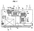
- FIG. 1 is a front view showing a dry vacuum pump unit according to an embodiment of the present invention.
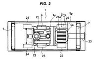
- FIG. 2 is a top view showing the dry vacuum pump unit according to the embodiment of the present invention.
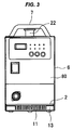
- FIG. 3 is a left side view showing the dry vacuum pump unit according to the embodiment of the present invention.
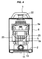
- FIG. 4 is a right side view showing the dry vacuum pump unit according to the embodiment of the present invention.
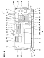
- FIG. 5 is a schematic diagram for explaining the flow of cooling air and the heat transfer state of the dry vacuum pump unit according to the embodiment of the present invention.
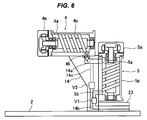
- FIG. 6 is a schematic diagram showing an arrangement state of the booster pump and the main pump of the dry vacuum pump unit according to the embodiment of the present invention.
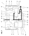
- FIG. 7 is a diagram showing the flow of exhaust gas during the operation of the dry vacuum pump unit according to the embodiment of the present invention.
- FIG. 8 is a cross-sectional view showing the main pump of the dry vacuum pump unit according to the embodiment of the present invention.
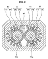
- FIG. 9 is a cross-sectional view of the motor portion of the main pump of the dry vacuum pump unit according to the embodiment of the present invention.
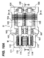
- 10A is a cross-sectional plan view of an air-cooled dry vacuum pump according to an embodiment of the present invention
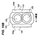
- FIG. 10B is a cross-sectional view taken along line AA in FIG. 10A
- FIG. 10C is a cross-sectional view taken along line BB in FIG.
- FIG. 10B is a diagram showing the pump casing and the cooling promotion structure of FIG. 10B.
- FIG. 10A is a cross-sectional plan view of an air-cooled dry vacuum pump according to an embodiment of the present invention
- FIG. 10B is a cross-sectional view taken along line AA in FIG. 10
- FIG. 11 is a graph showing the relationship between the number of turns of the screw vacuum pump and the intake pressure (Pa).
- FIG. 12 is a diagram showing the relationship between the number of turns of the screw vacuum pump and the compression work.
- FIG. 13 is a cross-sectional view showing a cooling promotion structure.
- FIG. 14 is a cross-sectional view showing another cooling promotion structure.
- FIG. 15 is a cross-sectional view showing still another cooling promotion structure.
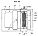
- FIG. 16 is a plan view showing an air-cooled dry vacuum pump according to another embodiment of the present invention.
- FIG. 17 is a plan view showing an air-cooled dry vacuum pump according to still another embodiment of the present invention.
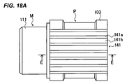
- 18A is a plan view showing an air-cooled dry vacuum pump according to still another embodiment of the present invention, and FIG.
- FIG. 18B is a cross-sectional view taken along line EE of FIG. 18A.
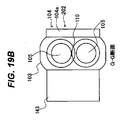
- FIG. 19A is a side sectional view showing an air-cooled dry vacuum pump according to still another embodiment of the present invention
- FIG. 19B is a sectional view taken along line GG in FIG. 19A.
- FIG. 20 is a diagram showing a configuration example of a pump drive motor of an air-cooled dry vacuum pump according to the present invention.
- FIGS. 1 to 4 are diagrams showing a configuration of a dry vacuum pump unit according to an embodiment of the present invention.
- FIG. 1 is a front view
- FIG. 2 is a top view
- FIG. 3 is a left side view
- FIG. It is.
- the dry vacuum pump unit 1 includes a heat radiating plate 2.
- an electrical component 3 On the heat radiating plate 2, an electrical component 3, a modular booster pump 4, and a modular main pump 5 are provided.
- the dry vacuum pump unit 1 is entirely covered with an exterior cover 6, and can be moved to a predetermined position on the upper surface of the exterior cover 6 with both hands and moved to a place where the dry vacuum pump unit 1 is used.
- the heat radiating plate 2 is provided with a number of heat radiating fins 11 protruding downward.
- the heat sink 2 is disposed above the bottom cover 2 a, and the lower side of the exterior cover 6 is attached to both sides of the heat sink 2.
- An air flow path 13 (first air flow path) through which cooling air passes is formed by the heat radiating plate 2 and the bottom cover 2a, and a large number of the radiating fins 11 have a flow of air flowing through the air flow path 13 in the longitudinal direction. It is arranged toward the.
- the electrical component 3 is a variety of electric devices and electronic components such as a rectifier and an inverter that constitute a drive unit that drives the booster pump 4 and the main pump 5 and a control unit that controls the booster pump 4, and is mounted on the heat sink 2.
- a pump installation base 14 for attaching the booster pump 4 and the main pump 5 to the heat radiating plate 2 is provided.
- the booster pump 4 is attached horizontally via an upper surface plate 14d of the pump installation base 14, and the main pump 5 is installed in the pump. It is attached vertically via a column 14e of the base 14.
- the heat radiating plate 2 is formed in a substantially rectangular flat plate shape.
- a flow path (first air flow path) 13 is formed.
- the front end of the air circulation (first air flow path) 13 (the end on the front side of the electrical component 3) is exposed near the lower part of the front surface of the exterior cover 6 (the surface on which the soundproof hood 80 is installed).
- the opening of the air flow path 13 serves as an air intake port 13a for introducing air.
- the rear end of the air flow path 13 (the side on which the soundproof hood 85 is installed) serves as an air discharge port 13 b that opens at the lower portion of the main pump 5.
- each heat radiation fin 11a extends from the front toward the rear.
- the lower surface of the column portion 14e of the pump installation base 14 and the lower surface of the electrical component 3 are fixed.
- the electrical component 3 is on the opposite side of the upper surface of the pump installation table 14 where the booster pump 4 is installed (the lower surface side of the upper plate portion 14d) and on the opposite side of the side of the pump installation table 14 where the main pump 5 is installed. It is installed so as to be located at a position (on the opposite side to which the main pump 5 of the column portion 14d is attached).
- the exterior cover 6 is box-shaped, and an air intake port 6a is provided near the top of the front surface (the surface on the side where the air intake port 13a of the air flow path 13 is located). An air discharge port 6b is provided in the vicinity of the upper portion.
- a cooling fan 18 is installed at a position facing the air discharge port 6 b in the exterior cover 6. The cooling fan 18 is for forcibly discharging air that has been introduced from the air intake ports 6a and 13a and has cooled the internal devices and discharged from the port 6b to the outside.
- the air introduced into the exterior cover 6 from the air intake port 6a mainly flows through the space 19 (second air flow path) in the exterior cover 6.
- the discharge port of the cooling fan 18 may be the air discharge port 6b as it is.
- An air intake hood 80 is attached at a position facing the air intake port 6a outside the exterior cover 6 so as to be parallel to the front surface of the exterior cover 6 with a predetermined gap from the air intake port 6a.
- the air intake hood 80 plays a role as a soundproof hood.
- the air intake hood 80 has an opening 81 on the lower side and is opened, and the other three sides have side walls bent on the exterior cover 6 side. Air is configured to be introduced into the space (second air flow path) 19 from the opening 81.
- a sound absorbing material 83 that silences noise leaking from the air intake port 6a is provided on the surface (inner surface) of the air intake hood (soundproof hood) 80 that faces the air intake port 6a.
- the sound absorbing material 83 is formed by forming a sponge-like flexible material into a plate-like body having a predetermined thickness.
- the air intake hood (soundproof hood) 80 is also an operation panel for operating the dry vacuum pump unit 1, and is provided with an operation button, a stop button, an alarm reset button, and the like on its outer surface, An LED lamp for display, an accumulated operation time display panel, and the like are provided.
- the air intake hood (soundproof hood) 80 is electrically connected to the electrical component 3 by a lead wire or the like.
- An air discharge hood 85 is attached at a position facing the air discharge port 6 b outside the outer cover 6 so as to be parallel to the outer cover 6 with a predetermined gap from the air discharge port 6 b.
- the air exhaust hood 85 also serves as a soundproof hood.
- the air exhaust hood 85 is opened with an opening 87 on its lower side, and the other three sides are bent toward the exterior cover 6 side. By having the side wall, air is mainly discharged from the opening 87.
- the sound absorbing material 89 is also configured by forming a sponge-like flexible material into a plate-like body having a predetermined thickness in this embodiment, but various other materials and shapes may be used.
- the space 19 is That is, the electrical component 3 and the booster pump 4 having a small heat generation amount are arranged on the upstream side of the flowing air flow, and the main pump 5 having a large heat generation amount is arranged on the downstream side. That is, the arrangement structure is such that the air flowing through the space 19 flows from a low temperature region to a high temperature region. As shown in FIGS.
- a heat radiating plate 24 having heat radiating fins 24a is attached to the outer wall side surface of the motor portion 4m of the booster pump 4, and heat radiating fins 25a are provided on the outer wall side surface of the pump portion 4p.
- a heat radiating plate 25 is attached.
- a heat radiating plate 24 having heat radiating fins 24a is attached to the outer wall side surface of the motor portion 5m of the main pump 5, and a heat radiating plate 25 having heat radiating fins 25a is attached to the outer wall side surface of the pump portion 5p.
- the bottom cover 2a is made of a rigid steel plate, and the heat radiating plate 2 on which the electrical component 3, the booster pump 4 and the main pump 5 are mounted is made of an aluminum alloy having good thermal conductivity.
- the casings of the pump part 4p of the booster pump 4 and the pump part 5p of the main pump 5 are made of an aluminum alloy having good thermal conductivity, and the pump installation base 14 to which the booster pump 4 and the main pump 5 are attached has good thermal conductivity. It is composed of an aluminum alloy. Furthermore, the heat sinks 24 and 25 are also made of aluminum or aluminum alloy having good thermal conductivity. You may comprise the heat sink 2, the pump installation stand 14, and the booster pump 4 and the main pump 5 which were modularized with an integral material. In this case, the thermal resistance of the contact portion is reduced, and heat conduction from the module portion to the heat radiating plate is good, which is preferable.
- heat generated by the electrical component 3, the booster pump 4, and the main pump 5 during the pump operation is transferred to the heat radiating plate 2.
- the cooling air flowing in from the air intake port 13a of the air flow path 13 by the cooling fan 18 flows while contacting the heat radiating fins 11 of the heat radiating plate 2 exposed in the air flow path 13 as indicated by an arrow B.
- the heat collected in the heat sink 2 is efficiently radiated. Furthermore, it contacts the heat radiating fins 25a of the heat radiating plate 25 attached to the outer wall surface of the pump part 5p of the main pump 5 to cool the pump part 5p.
- the cooling air flowing in from the air intake port 16 a at the lower end of the air intake hood 16 flows into the space (second air flow path) 19 in the exterior cover 6 as indicated by an arrow A, and the motor portion 4 m of the booster pump 4.
- the heat radiation fins 24a and 25a of the heat radiation plates 24 and 25 attached to the side of the outer wall of the pump part 4p, the motor part 4m and the pump part 4p are cooled, and further attached to the outer wall surface of the motor part 5m of the main pump It contacts the heat radiating fins 24a of the heat radiating plate 24 and cools the motor portion 5m.
- the air flow indicated by the arrows A and B flows into the air exhaust hood (soundproof hood) 85 and is exhausted to the outside through the opening 87 at the lower end of the air exhaust hood (soundproof hood) 85.
- the operation of one cooling fan 18 causes the flow of air flowing in the air flow path (first air flow path) 13 and the flow of air flowing in the space (second air flow path) 19 in the exterior cover 6.
- a flow is formed.
- the heat generation amount of the electrical component 3 arranged on the upstream side, the motor unit 4m of the booster pump 4 and the pump unit 4p is the motor unit 5m and pump unit of the main pump 5 arranged on the downstream side. Less than 5p calorific value.
- the cooling air flows from the portion with the low temperature rise (the portion with the low temperature) to the portion with the high temperature rise (the portion with the high temperature).
- the cooling efficiency is improved. That is, the electrical component 3 having a low temperature rise, the motor part 4m and the pump part 4p of the booster pump 4 are arranged on the upstream side of the cooling air flow, and the air compression ratio of the dry vacuum pump unit 1 is the largest on the downstream side.
- the exhaust port 4 b of the pump unit 4 p of the booster pump 4 and the intake port 5 a of the pump unit 5 p of the main pump 5 are communicated with each other through a communication passage 14 a formed in the pump installation base 14.
- An intake pipe 22 is connected to the intake port 4a of the pump unit 4p of the booster pump 4 (see FIGS. 1 to 4), and the exhaust port 5b of the pump unit 5p of the main pump 5 is connected to a check valve (pressure release valve) V1. And is connected to an exhaust passage 14b formed in the pump installation base 14.
- An exhaust pipe 23 is connected to the exhaust passage 14b.
- a pressure release passage 14c that connects the communication passage 14a and the pressure release passage 14b is formed in the pump installation base 14, and a check valve (pressure release valve) V2 is provided in the pressure release passage 14c. That is, the check valve V2 for hollowing out is provided in the pressure release passage 14c that connects the exhaust port 4b of the pump portion 4p of the booster pump 4 and the exhaust passage 14b.
- a DC pulse current is supplied from the motor driver 27 of the control unit 26 to the motor unit 4m of the booster pump 4 and the motor unit 5m of the main pump 5 to be driven.
- the cooling fan 18 is also controlled by the control unit 26.
- the check valve (pressure release valve) V ⁇ b> 2 opens and communicates with the outside air via the exhaust pipe 23.
- the check valve (pressure release valve) V2 has a structure in which a valve body pressurized by a spring presses an elastic body such as an O-ring (rubber ring) to seal the flow path, and the communication passage 14a. It opens only when the internal pressure becomes higher than the external pressure.
- the material of the pump mounting base 14 may be another material such as titanium or stainless steel.
- the check valve (pressure release valve) V2 prevents gas overcompression and is safe, and at the same time, increases the power required for exhausting when the vacuum vessel is at the external pressure (when the intake side pressure is equal to the external pressure). Can be prevented.
- the operation of the main pump 5 can be continued while maintaining the exhaust speed of the booster pump 4 as it is, and a decrease in the exhaust flow rate at the time of activation can be prevented, and a desired vacuum degree can be reached in a short time. That is, when the check valve (pressure release valve) V2 is not provided, in order to avoid gas overcompression, the main pump is first evacuated and the booster pump is started after a vacuum is reached to some extent, or the booster pump is set low in advance. The main pump was started while operating at the rotational speed. In this case, since the exhaust speed at startup is mainly determined by the main pump, there is a problem that the exhaust flow rate is low and a certain amount of time is required to reach a predetermined degree of vacuum.
- the check valve (pressure release valve) V2 gas at an external pressure can be directly exhausted with a booster pump having a high exhaust speed, and the required degree of vacuum can be reached in a short time.
- the check valve (pressure release valve) V2 when a differential pressure is generated between the upstream side and the downstream side, the valve is immediately closed, and when the differential pressure is eliminated, the valve is immediately opened. Is mentioned. For this reason, when the intake side changes from the external pressure to the vacuum pressure, the valve is quickly closed and there is no loss of exhaust time.
- the check valve (pressure release valve) V2 is always closed, so that the exhaust sound of the booster pump 4 does not leak to the outside.
- the check valve (pressure release valve) V1 attached to the exhaust passage 14b connected to the exhaust port 5b of the main pump 5 also has a structure in which the valve body pressurized by the spring presses the O-ring (rubber ring). have.
- the check valve (pressure release valve) V1 is almost closed during the steady operation state in which the inside of the vacuum vessel is evacuated, and the exhaust sound of the main pump 5 can be blocked from leaking to the outside. Even when the operation of the main pump 5 is stopped due to some abnormality, the check valve (pressure release valve) V1 is closed, so that the vacuum state can be prevented from being broken.
- the control unit 26 supplies a DC pulse current from the motor driver to the motor unit 4m of the booster pump 4 arranged on the vacuum side, and first activates the booster pump 4, and then (several seconds After) A DC pulse current is supplied to the motor unit 5m of the main pump 5 to start the main pump 5.
- the gas flow generated by the activation of the booster pump 4 is caused to flow to the exhaust passage 14b through the hollow check valve V2.
- the electrical component 3 has a control unit 26 that electrically controls and drives the dry vacuum pump unit 1.
- the motor driver includes a motor driver for the main pump 5 and a motor driver for the booster pump 4. Yes, each independently drives the main pump 5 and booster pump 4 to rotate. Both motor drivers are supplied with, for example, 48V DC power from a common DC power supply (AC / DC converter), and each motor driver converts the DC power into a rectangular pulse waveform by PWM, and the motor unit 5m of the main pump 5 And the booster pump 4 is supplied to the motor unit 4m.
- the rotational speed of the main pump 5 on the external atmospheric pressure side is set to 13000. -1
- the rotation speed of the booster pump 4 on the vacuum side is 15000-21000 -1
- the rotational speed of the booster pump 4 is made higher than the rotational speed of the main pump 5.
- outside air pressure means the pressure in the ambient atmosphere of the dry vacuum pump unit 1, and more specifically, the pressure in the exhaust side space communicating with the dry vacuum pump unit 1. Since the ultimate pressure power is about 240 to 300 W, the power consumption is low, and the power of the dry vacuum pump unit 1 can be sufficiently supplied by an ordinary single-phase AC power source.
- this dry vacuum pump unit 1 can be used as a portable vacuum pump wherever a single-phase AC power source can be used.
- the main pump 5 and the booster pump 4 are pumps having the same structure, but by operating the booster pump 4 at a speed higher than that of the main pump 5, a vacuum pump that cannot be obtained at all by operating this type of vacuum pump.
- An ultimate vacuum of about 1 Pa or less (for example, 0.5 Pa) is obtained on the container side.
- a timer is provided in the control unit 26, and the cooling fan 18 is activated simultaneously with the activation of the dry vacuum pump unit 1.
- the timer is activated when the pump is stopped, and after a predetermined set time (for example, after 15 to 30 minutes). That is, the cooling fan 18 is stopped after the heat in the pump module (particularly the main pump 5) is sufficiently dissipated and the temperature drops. Thereby, fan operation noise and power consumption due to operation of the cooling fan 18 when the dry vacuum pump unit 1 is stopped can be reduced.
- the present invention is not limited to stopping the cooling fan 18 after elapse of a set time by the timer, but is a sensor for detecting the temperature of each part of the dry vacuum pump unit 1, for example, a temperature for detecting the temperature in the main pump 5 having a high temperature rise.
- a sensor may be provided, and the output of the sensor may be output to the control unit 26, and the control unit 26 may stop the cooling fan 18 when the temperature falls below a predetermined temperature.
- 8 and 9 are diagrams showing the configuration of the main pump 5 that is modularized in the dry vacuum pump unit 1. Since the booster pump 4 and the main pump 5 have the same configuration, the main pump 5 will be described here. The booster pump 4 and the main pump 5 do not need to have the same configuration.
- the main pump 5 is composed of a motor unit 5m and a pump unit 5p.
- the motor unit 5m is a magnet coupling type DC brushless resin mold motor.
- the pump unit 5p synchronously reverses a pair of screw rotors to supply gas. It is a vacuum pump to transfer, and is a volume transfer type twin screw pump.
- the main pump 5 includes a casing 50, and two rotary shafts 51 a and 51 b are arranged in parallel inside the casing 50, and each rotary shaft 51 a and 51 b is a bearing 53. It is supported by.
- a right-handed screw rotor (pump rotor) 52a is fixed to the rotating shaft 51a
- a left-handed screw rotor (pump rotor) 52b is fixed to the rotating shaft 51b.
- a fluid passage 56 is formed between the screw rotors 52 a and 52 b and the inner surface of the casing 50, an intake port 5 a is provided at the upstream end of the fluid passage 56, and an exhaust port is provided at the downstream end of the fluid passage 56. 5b is provided.
- the screw rotors 52a and 52b are reversed in contact with each other while maintaining a slight clearance so that the gas sucked from the intake port 5a is transferred to the exhaust port 5b.
- the screw rotors 52a and 52b As the screw rotors 52a and 52b, a pair of screw rotors having an axial cross-sectional shape that contacts only on the pitch line may be used.
- the rotary shafts 51a and 51b are made of SUS material
- the screw rotors 52a and 52b are made of aluminum alloy
- the screw rotors 52a and 52b are shrink-fitted on the rotary shafts 51a and 51b to form a pair of pump rotors. is doing.
- the surfaces of the screw rotors 52a and 52b are subjected to nickel plating.
- the screw rotors 52a and 52b are made of a resin material and may be formed on the outer periphery of the rotary shafts 51a and 51b.
- screw rotor 52a, 52b can be manufactured at low cost.
- a pair of magnet rotors 54, 54 having the same configuration are arranged at the shaft ends on the intake side of the rotation shafts 51a, 51b, respectively, and the rotation shafts 51a, 51b are driven in reverse as brushless DC motors. Synchronous reversal of the rotating shafts 51a and 51b is ensured.
- each magnet rotor 54 has a ring-shaped magnet 54a around the outer periphery of a magnetic material yoke 54b.
- a magnet 54a magnetized in six poles is provided on the outer periphery of the magnet rotor 54, facing each other so that the different magnetic poles of the magnet rotors 54 and 54 attract each other, and maintaining a clearance C. Is arranged.
- the number of poles of the magnet rotor 54 is an even number such as 6, 8, 10, 12 or the like, and is 6 here.
- the screw rotors 52a and 52b are synchronously rotated in opposite directions by the magnet coupling action of the magnet rotors 54 and 54. Thereby, the screw pump which can perform the stable biaxial synchronous inversion even if there is no timing gear is comprised.
- the rotation speed is generally 6000 to 7000 min. -1
- the rotation speed is generally 6000 to 7000 min. -1
- the magnet coupling as described above, 10,000 to 30,000 min. -1
- the rated rotational speed of the booster pump 4 is 21000 min.
- a three-phase (U, V, W) motor stator 57 including an iron core 57a and a winding 57b is disposed in the vicinity of a part of the outer peripheral surface of each magnet rotor 54.
- the three-phase motor stator 57 is disposed on the side opposite to the side where the magnet rotors 54 are magnet-coupled with respect to the rotation axis. Thereby, the magnet coupling force that the magnet rotors 54 attract each other can be canceled by the attraction force acting on the magnet rotor 54 and the motor stator core 57a.
- the three-phase motor stator magnetic poles correspond to the number of magnetic poles of the magnet rotor 54, and a magnetic field is applied to the four poles of the magnet rotor 54.
- the two rotating shafts 51a and 51b can be synchronously inverted and driven at an arbitrary rotational speed.
- the gas flows in the axial direction as the screw rotors 52a and 52b rotate. Therefore, as shown in FIG. 1, when the main pump 5 is installed vertically and the exhaust port 5b is disposed below the intake port 5a, the exhaust port 5b is located at the lower end of the fluid passage 56.
- the flow of water (condensed water or the like) into the casing 50 can be prevented by the action of gravity, and overload and corrosion of the main pump 5 can be prevented.
- the magnet rotor 54 and the motor stator 57 are located above the screw rotors 52a and 52b (above the fluid passage 56), even if water flows in from the exhaust port 5b, these parts are There is no contact.
- the main pump 5 is arranged to have an angle with respect to the horizontal direction so that the exhaust port 5b is positioned below the intake port 5a.
- the screw rotor of the main pump 5 is used. 52a and 52b are arranged substantially vertically.
- the check valve (pressure release valve) V2 When the pressure in the communication passage 14a becomes larger than the external air pressure around the dry vacuum pump unit 1, the check valve (pressure release valve) V2 is opened, the pressure in the communication passage 14a is released, and the booster pump 4 The load of is constant.
- the pressure in the vacuum vessel decreases, the pressure in the communication passage 14 also decreases, so that the check valve (pressure release valve) V2 is closed. Further, the load on the booster pump 4 is also reduced.
- the pressure difference between the intake side and the exhaust side of the booster pump 4 is small (both intake and exhaust sides are in a vacuum state), so the booster pump 4 is in a state close to no-load operation. become.
- the load of the main pump 5 is close to the rated value.
- the check valve (pressure release valve) V1 is momentarily closed, so that the vacuum in the vacuum vessel can be prevented from being broken.
- the dry vacuum pump unit 1 it is possible to perform a start-up and steady operation without detecting a pressure and a flow rate without detecting a pressure and a flow rate.
- the operation of the cooling fan 18 is started, and air is introduced into the exterior cover 6 from the air intake ports 6a and 13a.
- the cooling of the main pump 5 by the air from the air flow path 13 is effective. It is. Then, the air discharged from the air discharge port 6b passes through the gap between the air discharge hood (soundproof hood) 85 and the exterior cover 6 from the horizontal direction, and the air flow is changed to a direction substantially directly below.
- the hood 85 is discharged from the opening 87 on the lower end side. As described above, since the dry vacuum pump unit 1 cools the heat generated from the various internal components by air cooling, the exterior cover 6 needs the air intake port 6a and the air discharge port 6b.
- noise generated from the main pump 5, the booster pump 4, the cooling fan 18 and the like also leaks out from the air intake port 6a and the air discharge port 6b.
- the direction of the flow of the discharged air discharged from the air discharge port 6b is changed by the air discharge hood (soundproof hood) 85 installed outside the air discharge port 6b (substantially).
- the noise that leaks outside from the air outlet 6b is reflected one or more times between the air exhaust hood (soundproof hood) 85 and the exterior cover 6 (part of the reflected noise is the exterior cover). 6) and then released to the outside. This effectively attenuates noise.
- the air discharge hood (soundproof hood) 85 is only installed so as to face the air discharge port 6b, the structure is simple and can be configured in a compact structure.
- the direction of the flow of the introduced air before being introduced into the air intake port 6a is changed by the air intake hood (soundproof hood) 80 installed outside the air intake port 6a (substantially). Noise that leaks to the outside from the air intake port 6a is reflected one or more times between the air intake hood (soundproof hood) 80 and the exterior cover 6 (part of the reflected noise is the exterior cover). 6) and then released to the outside. This effectively attenuates noise.
- the air intake hood (soundproof hood) 80 is only installed so as to face the air intake port 6a, the structure is simple and can be configured in a compact structure without being bulky.
- the air intake hood (soundproof hood) 80 also serves as an operation panel, the dry vacuum pump unit 1 can be configured more compactly.
- sound absorbing materials 83 and 89 are attached to the reflective surfaces of the air intake hood (soundproof hood) 80 and the air exhaust hood (soundproof hood) 85 so that the noise is absorbed and attenuated more effectively. it can.
- the electrical component 3 is on the opposite side of the upper surface of the upper plate portion 14d on which the booster pump 4 of the pump installation base 14 is installed, and on the opposite side of the side surface of the column portion 14e on which the main pump 5 of the pump installation base 14 is installed.
- the air intake port 13 a of the air flow path 13 is disposed under the exterior cover 6 in front of the electrical component 17. Since the air intake port 13a of the air flow path 13 is disposed at a position farthest from the main pump 5 and the booster pump 4, noise generated from the main pump 5 and the booster pump 4 reaches the air intake port 13a. This makes it difficult to prevent noise leakage from the air intake port 13a.
- the cooling mechanism can be simplified and the weight can be reduced accordingly. Also, since no cooling water is used, there is no need for cooling water equipment, and if there is a drive power supply (AC100V, AC200V), it can be moved and installed by handling and can be operated simply by connecting the power supply. . In addition, since the timing gear is not used, it is possible to further reduce the weight (20 kg or less) without using a lubricating oil, without needing a lubricating system for lubricating oil and replacement of the lubricating oil.
- FIG. 10A is a plan sectional view showing an air-cooled dry vacuum pump according to an embodiment of the present invention
- FIG. 10B is a sectional view taken along line AA in FIG. 10A
- FIG. 10C is a sectional view taken along line BB in FIG. 10D is a diagram illustrating the pump casing and the cooling promotion structure of FIG. 10B.
- the air-cooled dry vacuum pump includes a pump part P and a motor part M.
- a casing 103 (pump casing) of the pump unit P includes an intake port 101 and an exhaust port 102, and a rotor housing space 109 in which a pair of rotors (pump rotors) 105 are rotatably housed in the casing 103. Is formed.
- the transverse cross section of the rotor accommodating space 109 has a shape in which both sides are arc-shaped and a convex portion 110 is formed in a portion located between the pump rotors 105.
- Each pump rotor 105 disposed in the rotor accommodating space 109 is rotatably supported at both ends by a bearing 107 and a bearing 108.
- the motor unit M includes a casing (motor casing) 111 attached to an end of the pump casing 103, and a motor stator 112 is disposed in the casing 111.
- a rotor storage space 114 in which two motor rotors 113 are rotatably arranged is formed in the motor stator 112.
- the end of the motor rotor 113 of the motor unit M is connected to the shaft end of each pump rotor 105.
- the motor unit M is a two-axis synchronous inversion drive motor in which two axes are synchronously inverted. By starting the two-axis synchronous inversion drive motor, the pair of pump rotors 105 of the pump part P are synchronously inverted.
- the gas in the space surrounded by the pump rotor 105 and the pump casing 103 is compressed by synchronously inverting the pair of pump rotors 105 of the pump portion P.
- the pump casing 111 is provided with an intake port 101 and an exhaust port 102, and the exhaust port 102 is connected to the intake port 101 under atmospheric pressure. -3 It can be exhausted to ⁇ 10 Torr.
- the vacuum pump is operated in a state where the intake port 101 is close to the deadline, for example, in the case of a screw type vacuum pump with six turns, the compression work is as shown in FIGS. Most of the processing is performed up to about 3 turns when viewed from the exhaust port 102 side.
- the convex portion 110 of the portion located between the pump rotors 105 and 105 of the pump casing 103 is likely to increase in temperature as compared with other portions, and is likely to be distorted by heat.
- the cooling promotion structure 104 is provided in the portion where the rotor housing space 109 of the pump casing 103 is formed and in the portion where the heat generation amount on the exhaust port 102 side is large. ing.
- the cooling facilitating structure 104 is provided in the portion where the rotor housing space 109 of the pump casing 103 is formed and in the portion where the heat generation amount on the exhaust port 102 side is large.
- the cooling efficiency of the convex portion 110 that tends to be higher in temperature than the arc portions 109a and 109a on both sides of the rotor housing space 109 can be increased, temperature unevenness in the circumferential direction of the pump casing 103 can be suppressed, and the pump Clearance change due to distortion deformation of the casing 103 can be prevented.
- the cooling promotion structure 104 is configured to include a large number of heat radiation fins 104 a, and in this example, the cooling promotion structure 104 is provided integrally with the pump casing 103.
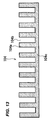
- FIGS. 13, 14, and 15 are diagrams illustrating different examples of the cooling promotion structure 104.
- a large number of heat radiation fins 104a are provided on the heat radiation plate 104c, and gap grooves 104b are provided between the heat radiation fins 104a and the heat radiation fins 104a.
- the cooling promoting structure 104 is attached to a portion where the rotor housing space 109 of the pump casing 103 is formed and a portion where the heat generation amount on the exhaust port 102 side is large (see FIG. 10A and the like).
- the direction of the gap groove 104b may be a direction orthogonal to the axial direction of the pump rotor 105 or a direction parallel to the axial direction.
- the cooling promoting structure 104 shown in FIG. 14 has a large number of spaces 104d therein. As described above, the cooling promotion structure 104 provided with the large number of spaces 104d is a portion where the rotor housing space 109 of the pump casing 103 is formed and a portion where the heat generation amount on the exhaust port 102 side is large (FIG.
- cooling promotion structure 104 shown in FIG. 15, a large number of heat radiation fins 104′a are provided on the upper surface of the cooling promotion structure 104 shown in FIG. 14, and a gap groove 104′b is formed between the heat radiation fins 104′a and the heat radiation fins 104′a. Is provided.
- the cooling promotion structure 104 having such a structure is attached to a portion where the rotor housing space 109 of the pump casing 103 is formed and a portion where the heat generation amount on the exhaust port 102 side is large (see FIG. 10A and the like).
- FIG. 16 is a plan view of an air-cooled dry vacuum pump according to another embodiment of the present invention.
- This air-cooled dry vacuum pump includes an exterior cover 120 having a size that covers the entire outer periphery of the vacuum pump illustrated in FIGS. 10A to 10D, and a pump portion P illustrated in FIGS. 10A to 10D is provided inside the exterior cover 120. And a vacuum pump comprising the motor part M is accommodated.
- An exhaust port 123 is provided on the side surface in the vicinity of the cooling promoting structure 104 on the pump part P side of the exterior cover 120, a cooling fan 121 is attached in the exhaust port 123, and air is taken into the side surface on the opposite side of the exhaust port 123.
- a mouth 122 is provided.
- FIG. 17 is a plan view of an air-cooled dry vacuum pump according to still another embodiment of the present invention. Similar to the vacuum pump shown in FIG.
- this air-cooled dry vacuum pump includes an outer cover 130 having a size covering the entire outer periphery of the vacuum pump shown in FIGS. 10A to 10D. And a vacuum pump comprising the motor part M is accommodated.
- An air intake port 132 for taking in external air is provided on the side surface of the exterior cover 130 on the motor unit M side, and an exhaust port 133 is provided on the side surface on the opposite side to the pump unit P side and in the vicinity of the cooling promotion structure 104.
- a cooling fan 131 is attached in the exhaust port 133.
- the cooling fan 131 By operating the cooling fan 131, as indicated by an arrow D, the cooling fan 131 flows into the exterior cover 130 from the outside through the air intake port 132, and the cooling fins 104a, the fins 104a, and the fins 104a of the cooling promotion structure 104 are flown.
- the cooling fan 131 by operating the cooling fan 131, the flow of outside air generated flows into the exterior cover 30 from the air intake port 132 provided on the side surface of the motor part M of the exterior cover 130, and the temperature is reduced.
- the surface of the pump casing 103 flows from the intake port 101 side to the shaft end side of the pump rotor 105, and further flows out from the exhaust port 133 through the cooling promotion structure 104.
- the air that has flowed into the exterior cover 130 flows from a low temperature portion to a high temperature portion.
- efficient heat dissipation can be performed, and cooling efficiency can be improved.
- the exhaust heat of the motor is reduced.
- the exhaust side of the pump rotor 105 of the pump casing 103 of the pump casing 103 that sucks outside air from the lower temperature and generates a large amount of heat. Since the air is discharged from the exhaust port 133 through the air, the adverse effect due to the heating of the outside air flowing into the exterior cover 130 is not given to other portions.
- Aluminum, an alloy thereof, graphite, or the like is used as a material for the heat dissipating fins 104a of the cooling promotion structure 104 or the heat transfer member.
- the radiating fins 104 a may be formed integrally with the pump casing 103.
- FIG. 18A is a plan view showing an air-cooled dry vacuum pump according to still another embodiment of the present invention
- FIG. 18B is a cross-sectional view taken along line EE of FIG. 18A.
- a material having poor thermal conductivity is used for the pump casing 103. Since the internal structure of the pump part P and the motor part M is the same as the air-cooled dry vacuum pump shown to FIG.
- a heat transfer member 140 made of a good material is provided, and a heat radiating plate 141 having a large number of heat radiating fins 141 a is provided on the heat transfer member 140.
- the direction of the heat radiation fin 141 a and the groove 141 b between the heat radiation fin 141 a and the heat radiation fin 141 a is parallel to the axial direction of the pump rotor 105.
- the heat transfer member 140 made of a material having good heat conductivity is attached to the highest temperature portion of the pump casing 103, and the heat dissipation plate 141 having a large number of heat radiation fins 141a is attached to the heat transfer member 140. Therefore, the heat generated at the highest temperature portion is transferred to the heat radiating plate 141 through the heat transfer member 140, and is efficiently radiated from the surface of the main body of the heat radiating plate 141 and the surface of the heat radiating fins 141a.
- the air-cooled dry vacuum pump having the configuration shown in FIGS.
- the exhaust port 133 may be provided in the vicinity of the cooling promoting structure 104 and accommodated in the exterior cover 130 in which the cooling fan 131 is attached.
- the air flow generated by operating the cooling fan 131 flows along the surface of the heat radiation fin 141a of the heat sink 141, the heat transmitted to the heat sink 141 can be efficiently radiated.
- the air flowing into the exterior cover 130 passes through the motor portion M having a low temperature and flows from the intake port 101 side of the pump unit P having a low temperature of the heat radiating plate 141 to the exhaust port 102 having a high temperature.
- FIG. 19A is a side sectional view showing an air-cooled dry vacuum pump according to still another embodiment of the present invention
- FIG. 19B is a sectional view taken along line GG in FIG. 19A.
- This air-cooled dry vacuum pump transfers heat to two air-cooled dry vacuum pumps 201 and 202 having the same configuration as the air-cooled dry vacuum pump shown in FIGS.
- the member 143 is mounted horizontally and vertically.
- FIG. 20 is a diagram illustrating an exemplary configuration example of a two-axis synchronous inversion drive motor that synchronously reverses a pair of pump rotors 105 of the pump unit P, that is, a motor unit M. As shown in FIG.
- the two-axis synchronous inversion drive motor includes a pair of magnet rotors (motor rotors) 113 and 113 having the same configuration, and inverts a pair of pump rotors 105 and 105 as a brushless DC motor. While being driven, synchronous reversal of the pump rotors 105 and 105 is secured by magnet coupling.
- Each magnet rotor 113 has a ring-shaped magnet 113a provided around the outer periphery of a magnetic material yoke 113b.
- a magnetized magnet 113 a is provided on the outer periphery of the magnet rotor 113, facing each other so that the different magnetic poles of the magnet rotors 113, 113 are attracted, and arranged with a clearance F maintained.
- the number of poles of the magnet rotor 113 is an even number such as 4, 6, 8,.
- the pump rotors 105 and 105 rotate in the opposite direction in synchronization by the magnet coupling action of the magnet rotors 113 and 113. Thereby, a screw pump capable of stable two-axis synchronous reversal without a timing gear is configured.
- a three-phase (U, V, W) motor stator 112 including an iron core 112a and a winding 112b is disposed in the vicinity of a part of the outer peripheral surface of each magnet rotor 113.
- the three-phase motor stator 112 is arranged on the side opposite to the side where the magnet rotors 113 are magnet-coupled with respect to the rotation axis. Thereby, the magnet coupling force that the magnet rotors 113 attract each other can be canceled by the attraction force that acts on the magnet rotor 113 and the motor stator core 112a. Further, the three-phase motor stator magnetic poles correspond to the number of magnetic poles of the magnet rotor 113, and a magnetic field is applied to the four poles of the magnet rotor 113 as shown by arrows G and H in FIG.
- the two-axis and one-set pump rotor 105 can be synchronously inverted and driven at an arbitrary rotational speed.
- a vacuum pump module is comprised by the two-stage vacuum pump of the main pump 5 arrange
- the vacuum pump is not limited to this, and may be a vacuum pump configured by a single stage or three or more stages of vacuum pumps. Further, for example, in the air-cooled dry vacuum pump shown in FIGS.
- the vacuum pump accommodated in the exterior covers 120 and 130 is the vacuum pump having the configuration shown in FIGS. 10A to 10D.
- the pump is not limited to a pump, and may be a volume transfer type air-cooled dry vacuum pump including a casing having an intake port and an exhaust port and a pair of two-shaft rotors disposed in the casing.
- the present invention is used as a vacuum pump having an exhaust capability with a vacuum ultimate pressure of about 1 Pa in an analyzer such as a sputtering apparatus, a helium leak detector, and an SEM.
- an analyzer such as a sputtering apparatus, a helium leak detector, and an SEM.
Landscapes
- Engineering & Computer Science (AREA)
- Mechanical Engineering (AREA)
- General Engineering & Computer Science (AREA)
- Applications Or Details Of Rotary Compressors (AREA)
Abstract
ドライ真空ポンプユニットは、必要な場所にハンドリングで移動することが可能な小型軽量で、且つ電装部品やポンプ等からの発熱を効率よく放熱して冷却できる。このドライ真空ポンプユニットは、真空側に配置されるブースターポンプ(4)と、外気圧側に配置されるメインポンプ(5)と、放熱フィン(11)を具備する放熱板(2)を備えている。放熱板(2)上に電装部品(3)が実装され、放熱板(2)上に熱伝導の良い材料で構成されたポンプ設置台(14)を介在させてブースターポンプ(4)及びメインポンプ(5)が取り付けられているか、又は放熱板(2)上に直接ブースターポンプ(4)及びメインポンプ(5)が取り付けられている。
Description
本発明は、真空到達圧力が1Pa程度、好ましくは0.5Pa程度のドライ真空ポンプユニット及びその起動方法、並びに、吸気口と排気口を有するケーシング内に2軸1組のロータを配置した容積移送式の空冷式ドライ真空ポンプに関する。
スパッタリング装置、ヘリウムリークディテクター、SEM等の分析装置等の用途に、真空到達圧力が1Pa程度の排気能力を持つ真空ポンプが用いられている。またターボ分子ポンプ等の高真空ポンプの粗引き用の真空ポンプとして、また、真空乾燥・真空貼り合わせ装置等のように水蒸気等のガスを吸引する目的にも上記排気能力を持つ真空ポンプが用いられている。
小容量で小型軽量の真空ポンプとしては、油回転ポンプが主流である。しかしながら、真空チャンバーへの油蒸気の逆拡散(真空チャンバー、ワークの油汚染)、排気ラインの油汚染(火災の危険)、環境汚染、油飛散による油の減少、水分混入等による油の劣化、汚損等、また定期的に必要な油補充・油交換等の問題がある。特に、真空ポンプ用のフッ素系油は一般に高価であり、交換作業も面倒である。
そこで、近年、油回転ポンプに代替する真空ポンプとして、スクロール型ドライ真空ポンプが登場してきた。スクロール型ドライ真空ポンプは、オイルフリーであり、スクロールの揺動運動により真空から大気圧まで連続的に圧縮するので、真空運転時の動力が小さく、比較的真空到達性能がよい等の特徴を有する。しかしながら、スクロールの端部にチップシール(接触シール)を使用するので、チップシールが磨耗してパーティクルが発生し、真空チャンバー内部を汚染するという問題がある。また、チップシールが磨耗するので、経年的に真空性能が低下し、連続運転1年程度でチップシール等を交換しなくてはならない。さらに、チップシールの交換作業の際は真空ポンプを分解しなくてはならず、交換費用が高価になる。また、同容量の油回転ポンプと比較して、大型でコストが高い等の問題がある。
真空ポンプの中で、半導体製造用途等で使用される比較的排気速度の大きい(1000L/min以上)真空ポンプとして、従来から多段ルーツ型やスクリュー型等の2軸容積移送式ドライ真空ポンプが使用されている。また、到達真空圧力が1Pa以下の真空排気性能と、さらに大きな排気速度を得るために、メインポンプとブースターポンプの2台のポンプを直列に配管接続して、1つの真空ポンプユニットを構成しているものもある。2軸容積移送式ドライ真空ポンプは、油回転ポンプのようにガス通路に油を使用していないので油汚染が無く、またスクロール型ドライ真空ポンプのようにチップシールを用いずに非接触動作が可能なので、チップシールの摩耗によるパーティクルの発生などもなく、半導体製造などに用いて好適である。
出願人は、スクリュー型の軸容積移送式真空ポンプユニットを提案している(特開2007−231935号公報参照)。この真空ポンプユニットは、外気圧側に配置されたメインポンプ(真空ポンプ)と、真空側に配置されたブースターポンプ(真空ポンプ)とを備え、ブースターポンプとメインポンプとを直列に接続して構成されている。ブースターポンプは、メインポンプより高い排気速度を有し、メインポンプ及びブースターポンプは、それぞれ一対のポンプロータと、吸気口及び排気口を有するポンプケーシングと、前記一対のポンプロータと一体に回転する一対のマグネットロータとを備えている。
上記特開2007−231935号公報に記載の真空ポンプユニットは、一対のマグネットロータのマグネットカップリング作用によりポンプロータを同期反転させることができ、これによりタイミンギヤを用いる必要がなくなり、オイルフリーとなる。この真空ポンプユニットにおいて、真空到達性能を維持し、ハンドリングで移動することが可能なように、小型・軽量化するためには、真空ポンプを高速で回転する必要がある。真空ポンプを高速で回転すると、ポンプモジュール、電装部品、モータ等で発生する熱量が多く、この発生した熱を効率良く放熱し、冷却して温度を低減させることが必要となる。
上記特開2007−231935号公報に記載の真空ポンプユニットに記載の真空ポンプユニットの起動方法は、先に外気圧側に配置されたメインポンプを起動してから、真空側に配置されたブースターポンプを起動する方法であった。ところが、このメインポンプとブースターポンプを駆動するモータ部は、それぞれ一対のマグネットロータのマグネットカップリング作用によりポンプロータを同期反転させる構成であるため、大気側に配置されたメインポンプを先に起動すると、メインポンプの起動によって生じる気体の流れによって、ブースターポンプの空回転が生じ、起動時に脱調する可能性がある。このため、真空ポンプユニットの起動時における制御の安定性が得られないという問題があることが判った。
上記特開2007−231935号公報に記載の真空ポンプユニットは、冷却ファンを取り付け、強制的に外部から空冷用の空気を外装カバー内に導入することで、各ポンプなどから発生する熱を外部に放出するようにしている。
しかしながら、外装カバーに設けた空冷用の空気取り込み口から外装カバーの内部に空気を導入し、導入した空気を冷却ファンによって強制的に外装カバーの空気吐出し口から外部に放出させるようにすると、空気吐出し口から放出される空気とともに真空ポンプ内部の騒音もそのまま外部に漏れて大きな騒音が発生し、同様に、空気取り込み口からも真空ポンプ内部の騒音が外部に漏れて大きな騒音が発生してしまうという問題があることが判った。
近年、大気圧から動作が可能で、クリーンな真空環境が容易に得られるドライ真空ポンプが、幅広い分野で使用されている。通常このような真空ポンプは、吸気側が締め切りに近い状態にて運転が行われるため、吸気口側と排気口側の差圧を維持する為に動力を消費している。つまり、排気口側からポンプ内部に逆流する気体を排気し続けることにより、吸気口側の真空度を維持している。このため真空ポンプ運転の消費動力の殆どは排気口側にて熱に変換される。真空ポンプの容量の大きさにもよるが、上記発熱に対して、従来はケーシングに水冷ジャケット等を設け、該水冷ジャケット内を通る水に熱を放熱する対策が採られていた(特開平8−319967号公報参照)。
しかしながら、真空ポンプを水冷で冷却するには、冷却水を得るための冷却水設備が必要になり、使用者の負担が大きくなるばかりではなく、真空ポンプを使用する場所も制限され、任意の場所で容易に真空を得られないという問題がある。
小容量で小型軽量の真空ポンプとしては、油回転ポンプが主流である。しかしながら、真空チャンバーへの油蒸気の逆拡散(真空チャンバー、ワークの油汚染)、排気ラインの油汚染(火災の危険)、環境汚染、油飛散による油の減少、水分混入等による油の劣化、汚損等、また定期的に必要な油補充・油交換等の問題がある。特に、真空ポンプ用のフッ素系油は一般に高価であり、交換作業も面倒である。
そこで、近年、油回転ポンプに代替する真空ポンプとして、スクロール型ドライ真空ポンプが登場してきた。スクロール型ドライ真空ポンプは、オイルフリーであり、スクロールの揺動運動により真空から大気圧まで連続的に圧縮するので、真空運転時の動力が小さく、比較的真空到達性能がよい等の特徴を有する。しかしながら、スクロールの端部にチップシール(接触シール)を使用するので、チップシールが磨耗してパーティクルが発生し、真空チャンバー内部を汚染するという問題がある。また、チップシールが磨耗するので、経年的に真空性能が低下し、連続運転1年程度でチップシール等を交換しなくてはならない。さらに、チップシールの交換作業の際は真空ポンプを分解しなくてはならず、交換費用が高価になる。また、同容量の油回転ポンプと比較して、大型でコストが高い等の問題がある。
真空ポンプの中で、半導体製造用途等で使用される比較的排気速度の大きい(1000L/min以上)真空ポンプとして、従来から多段ルーツ型やスクリュー型等の2軸容積移送式ドライ真空ポンプが使用されている。また、到達真空圧力が1Pa以下の真空排気性能と、さらに大きな排気速度を得るために、メインポンプとブースターポンプの2台のポンプを直列に配管接続して、1つの真空ポンプユニットを構成しているものもある。2軸容積移送式ドライ真空ポンプは、油回転ポンプのようにガス通路に油を使用していないので油汚染が無く、またスクロール型ドライ真空ポンプのようにチップシールを用いずに非接触動作が可能なので、チップシールの摩耗によるパーティクルの発生などもなく、半導体製造などに用いて好適である。
出願人は、スクリュー型の軸容積移送式真空ポンプユニットを提案している(特開2007−231935号公報参照)。この真空ポンプユニットは、外気圧側に配置されたメインポンプ(真空ポンプ)と、真空側に配置されたブースターポンプ(真空ポンプ)とを備え、ブースターポンプとメインポンプとを直列に接続して構成されている。ブースターポンプは、メインポンプより高い排気速度を有し、メインポンプ及びブースターポンプは、それぞれ一対のポンプロータと、吸気口及び排気口を有するポンプケーシングと、前記一対のポンプロータと一体に回転する一対のマグネットロータとを備えている。
上記特開2007−231935号公報に記載の真空ポンプユニットは、一対のマグネットロータのマグネットカップリング作用によりポンプロータを同期反転させることができ、これによりタイミンギヤを用いる必要がなくなり、オイルフリーとなる。この真空ポンプユニットにおいて、真空到達性能を維持し、ハンドリングで移動することが可能なように、小型・軽量化するためには、真空ポンプを高速で回転する必要がある。真空ポンプを高速で回転すると、ポンプモジュール、電装部品、モータ等で発生する熱量が多く、この発生した熱を効率良く放熱し、冷却して温度を低減させることが必要となる。
上記特開2007−231935号公報に記載の真空ポンプユニットに記載の真空ポンプユニットの起動方法は、先に外気圧側に配置されたメインポンプを起動してから、真空側に配置されたブースターポンプを起動する方法であった。ところが、このメインポンプとブースターポンプを駆動するモータ部は、それぞれ一対のマグネットロータのマグネットカップリング作用によりポンプロータを同期反転させる構成であるため、大気側に配置されたメインポンプを先に起動すると、メインポンプの起動によって生じる気体の流れによって、ブースターポンプの空回転が生じ、起動時に脱調する可能性がある。このため、真空ポンプユニットの起動時における制御の安定性が得られないという問題があることが判った。
上記特開2007−231935号公報に記載の真空ポンプユニットは、冷却ファンを取り付け、強制的に外部から空冷用の空気を外装カバー内に導入することで、各ポンプなどから発生する熱を外部に放出するようにしている。
しかしながら、外装カバーに設けた空冷用の空気取り込み口から外装カバーの内部に空気を導入し、導入した空気を冷却ファンによって強制的に外装カバーの空気吐出し口から外部に放出させるようにすると、空気吐出し口から放出される空気とともに真空ポンプ内部の騒音もそのまま外部に漏れて大きな騒音が発生し、同様に、空気取り込み口からも真空ポンプ内部の騒音が外部に漏れて大きな騒音が発生してしまうという問題があることが判った。
近年、大気圧から動作が可能で、クリーンな真空環境が容易に得られるドライ真空ポンプが、幅広い分野で使用されている。通常このような真空ポンプは、吸気側が締め切りに近い状態にて運転が行われるため、吸気口側と排気口側の差圧を維持する為に動力を消費している。つまり、排気口側からポンプ内部に逆流する気体を排気し続けることにより、吸気口側の真空度を維持している。このため真空ポンプ運転の消費動力の殆どは排気口側にて熱に変換される。真空ポンプの容量の大きさにもよるが、上記発熱に対して、従来はケーシングに水冷ジャケット等を設け、該水冷ジャケット内を通る水に熱を放熱する対策が採られていた(特開平8−319967号公報参照)。
しかしながら、真空ポンプを水冷で冷却するには、冷却水を得るための冷却水設備が必要になり、使用者の負担が大きくなるばかりではなく、真空ポンプを使用する場所も制限され、任意の場所で容易に真空を得られないという問題がある。
本発明は上述の点に鑑みてなされたもので、必要な場所にハンドリングで移動することが可能な小型軽量で、且つ電装部品やポンプ等からの発熱を、冷却水を用いることなく、効率よく放熱して冷却できるドライ真空ポンプユニットを提供することを第1の目的とする。
本発明は、起動時に脱調する恐れがなく、制御の安定性が得られるドライ真空ポンプユニット、及びその起動方法を提供することを第2の目的とする。
本発明は、空冷用の冷却ファンを有するドライ真空ポンプユニットにおいて、空気吐出し口や空気取り込み口から外部に漏れる騒音を効果的かつコンパクトな構造で減衰できるドライ真空ポンプユニットを提供することを第3の目的とする。
本発明は、冷却水設備を必要とすることなく、小型で任意の場所で容易に真空を得ることができる空冷式ドライ真空ポンプを提供することを第4の目的とする。
上記第1の目的を達成するため、本発明のドライ真空ポンプユニットは、真空側に配置されるブースターポンプと、外気圧側に配置されるメインポンプと、放熱フィンを具備する放熱板を備えている。放熱板上に電装部品が実装され、放熱板上に熱伝導の良い材料で構成されたポンプ設置台を介在させてブースターポンプ及びメインポンプが取り付けられるか、または放熱板上に直接ブースターポンプ及びメインポンプが取り付けられる。
本発明の好ましい一態様において、前記放熱フィンが露出する側にカバーを取り付けて該放熱フィンと前記カバーとの間に第1空気流路が形成され、前記電装部品、前記ブースターポンプ及び前記メインポンプを覆う外装カバーの内部に第2空気流路が形成され、前記第1空気流路及び前記第2空気流路に外部から冷却空気を導く冷却ファンが備えられている。
本発明の好ましい一態様において、前記第2空気流路内に配置される前記ブースターポンプ及び前記メインポンプの外側面に、放熱フィンを設けた放熱板が取り付けられている。
本発明の好ましい一態様において、前記ポンプ設置台はアルミニウム又はアルミニウム合金からなる。
本発明の好ましい一態様において、前記第2空気流路に沿って流れる空気流れの上流側に前記ブースターポンプが、下流側に前記メインポンプがそれぞれ配置されている。
本発明の好ましい一態様において、前記ブースターポンプ及び前記メインポンプは、それぞれモータ部とポンプ部を備え、前記ポンプ部は、一対のポンプロータと吸気口及び排気口を有するケーシングとを備え、前記モータ部は、前記一対のポンプロータと一体に回転する一対のマグネットロータを備えたマグネットカップリング型DCブラシレスモータである。
本発明の好ましい一態様において、前記外装カバーには、前記第2空気流路に空気を取り込む空気取り込みフードと、前記第1及び第2空気流路を流れる空気を外部に排出する空気排出フードが備えられ、前記空気取り込みフードの内面と空気排出フードの内面には、それぞれ吸音材が設けられている。
本発明の好ましい一態様において、前記冷却ファンの運転及び停止を行う制御部が備えられ、前記制御部は、ドライ真空ポンプユニットの起動と同時に前記冷却ファンの運転を開始し、該ドライ真空ポンプユニットの停止から所定時間経過後、又は該ドライ真空ポンプユニットの停止後温度が所定値以下になったら、前記冷却ファンを停止する。
本発明によれば、放熱板上に実装された電装部品、ブースターポンプ及びメインポンプで発生し放熱板に伝わった熱は、第1空気流路を流れる空気により効率よく放熱されて冷却される。電装部品、ブースターポンプ及びメインポンプの外側面の熱は、第2空気流路を流れる空気により効率よく放熱されて冷却される。このため、電装部品、ブースターポンプ及びメインポンプの信頼性が向上する。
ブースターポンプとメインポンプの外側面に放熱フィンを設けた放熱板を取り付けることで、ブースターポンプとメインポンプから発生する熱を放熱板の放熱フィンに接触する第2空気流路を流れる空気に効率よく放熱することができる。
ポンプ設置台をアルミニウム又はアルミニウム合金製とすることで、ブースターポンプとメインポンプで発生する熱は、熱伝導性の良いポンプ設置台を通って放熱板に集められて、第1空気流路を流れる空気に効率よく放熱される。
第2空気流路に沿って流れる空気流れの上流側にブースターポンプを、下流側にメインポンプをそれぞれ配置することで、ブースターポンプから発する熱量はメインポンプで発生する熱量より少ないから、空気は、温度の低い部分から温度の高い部分に流れることになり、ブースターポンプとメインポンプで発生する熱を効率よく放熱し冷却することができる。
ブースターポンプ及びメインポンプのモータ部を、一対のポンプロータと一体に回転する一対のマグネットロータを備えたマグネットカップリング型DCブラシレスモータとすることで、タイミングギヤが不要になり、該タイミングギヤを潤滑するための潤滑油や潤滑系が不要となり、その分、真空ポンプユニット全体の軽量化を図ることができる。
空気取り込みフードと空気排出フードの内面に、それぞれ吸音材を設けることにより、ドライ真空ポンプユニットを運転した際の騒音が外部に放出されることが抑制できる。
ドライ真空ポンプユニットの停止から所定時間経過後、又は該ドライ真空ポンプユニットの停止後温度が所定値以下になったら、冷却ファンを停止する制御部を備えることで、ドライ真空ポンプユニット停止後の冷却ファン運転による騒音を防止できる。
上記第2の目的を達成するため、本発明の他のドライ真空ユニットは、一対のポンプロータと吸気口及び排気口を有するケーシングとを備えたポンプ部と、前記一対のポンプロータと一体に回転する一対のマグネットロータを備えた構成のDCブラシレスモータ部を有するモジュール化したポンプを2組備え、一方のポンプは真空側に、他方のポンプは外気圧側にそれぞれ配置される。真空側のポンプの吐出口と外気圧側のポンプの吸込口を接続する流路と大気側との間にチェッキ弁が設けられ、ポンプ起動時、先ず真空側のポンプを起動させた後、外気圧側のポンプを起動させる制御部が設けられている。
本発明のドライ真空ポンプユニットの起動方法は、一対のポンプロータと吸気口及び排気口を有するケーシングとを備えたポンプ部と、前記一対のポンプロータと一体に回転する一対のマグネットロータを備えた構成のDCブラシレスモータ部を有するモジュール化したポンプを2組備え、一方のポンプを真空側に、他方のポンプを外気圧側にそれぞれ配置したドライ真空ポンプユニットを用意する。そして、先ず真空側のポンプを起動させた後、外気圧側のポンプを起動させ、真空側のポンプの起動によって生じる該真空側のポンプの排気口と外気圧側のポンプの吸込口とを接続する流路を流れる気体を該流路に接続したチェッキ弁を通して大気に放出する。
本発明によれば、先ず一方のポンプ(例えばブースターポンプ)を起動させた後、他方のポンプ(例えばメインポンプ)を起動させ、一方のポンプの起動によって生じる該ポンプの吐出口と他方のポンプの吸込口を接続する流路に流れる気体を該流路に接続したチェッキ弁を通して大気に放出することで、先に一方のポンプ(ブースターポンプ)を起動しても、他方のポンプ(メインポンプ)が空回転することがないから、起動時に脱調するという恐れがない。これよって、ドライ真空ポンプユニットの起動時における制御の安定性が向上する。
上記第3の目的を達成するため、本発明の更に他のドライ真空ポンプユニットは、外装カバー内に収納された真空ポンプと、前記外装ケースの外部から空冷用の空気を内部に導入する空気取り込み口と、前記空気取り込み口から導入されて前記外装ケースの内部の機器を冷却した空気を空気吐出し口から外装ケースの外部に排出させる冷却ファンとを有している。前記空気吐出し口に対向する空気吐出し口の外側位置には、空気吐出し口から吐出された吐出し空気の流れの向きを変える防音フードが取り付けられている。
このように、空気吐出し口の外側位置に吐出し空気の流れの向きを変える防音フードを取り付けることで、空気吐出し口から外部に漏れる騒音は防音フードと外装カバーとの間で1または複数回反射された後に外部に放出される。このため、騒音を効果的に減衰させることができる。また空気吐出し口に対向するように防音フードを設置するだけなので、構造が簡単でかさばることもなく、コンパクトな構造に構成できる。
本発明の好ましい一態様において、前記防音フードの前記空気吐出し口に対向する側の面に、空気吐出し口から外部に漏れる騒音を消音させる吸音材が取り付けられている。
このように、騒音が反射される防音フードの反射面に吸音材を取り付けることで、より効果的に騒音を減衰できる。
本発明の更に他のドライ真空ポンプユニットは、外装カバー内に収納された真空ポンプと、前記外装カバーの外部から空冷用の空気を内部に導入する空気取り込み口と、前記空気取り込み口から導入されて前記外装カバーの内部の機器を冷却した空気を空気吐出し口から外装カバーの外部に排出させる冷却ファンとを有している。前記空気取り込み口に対向する空気取り込み口の外側位置には、空気取り込み口に導入される前の導入空気の流れの向きを変える防音フードが取り付けられている。
このように、空気取り込み口の外側位置に導入空気の流れの向きを変える防音フードを取り付けることで、空気取り込み口から外部に漏れる騒音は防音フードと外装カバーとの間で1または複数回反射された後に外部に放出される。このため、騒音を効果的に減衰させることができる。また空気取り込み口に対向するように防音フードを設置するだけなので、構造が簡単でかさばることもなく、コンパクトな構造に構成できる。
本発明の好ましい一態様において、前記防音フードの前記空気取り込み口に対向する側の面に、空気取り込み口から外部に漏れる騒音を消音させる吸音材が取り付けられている。
このように、騒音が反射される防音フードの反射面に吸音材を取り付けることで、より効果的に騒音を減衰できる。
本発明の好ましい一態様において、前記防音フードは、ドライ真空ポンプユニットを操作する操作パネルである。
このように、防音フードを操作パネルと兼用させることで、ドライ真空ポンプユニットをよりコンパクトに構成できる。
本発明の好ましい一態様において、ドライ真空ポンプユニットは、略水平の上面と該上面から略垂下する側面とを有するポンプ設置台を備えており、前記ポンプ設置台の上面に真空側に配置されるブースターポンプが設置され、前記ポンプ設置台の側面に外気圧側に配置され前記ブースターポンプと直列に接続されるメインポンプが設置される。前記ポンプ設置台の前記ブースターポンプを設置した上面の反対面側であって且つ前記ポンプ設置台の前記メインポンプを設置した側面の反対面側の位置に電装部品が設置される。前記ポンプ設置台と前記電装部品は放熱板上に載置され、放熱板の下部に放熱板冷却用の空気を通す空気流路が設けられて一方の開口を外部の空気を導入する空気取り込み口とし、他方の開口を前記導入した空気を外装カバー内部に供給する空気吐出し口とし、前記空気取り込み口は、前記電装部品を設置した前方の外装カバー下部に配置されている。
このように、空気取り込み口を、メインポンプ及びブースターポンプからもっとも離れた位置に配置することで、メインポンプ及びブースターポンプから発生する騒音が空気取り込み口に到達しにくくなって、この空気取り込み口からの騒音漏れを防止できる。
上記第4の目的を達成するため、本発明の空冷式ドライ真空ポンプは、吸気口と排気口を有するケーシングと、該ケーシング内に配置される2軸1組のロータを具備している。前記2軸1組のロータはスクリュー式であり、前記ケーシングは、内部に前記吸気口と排気口が連通し、前記2軸1組のロータが並設して回転自在に収容される両側が円弧状で、該2軸間の略中央部が位置する部分が凸状に形成された断面形状のロータ収容空間が形成された構成である。前記ケーシングの少なくとも前記ロータ収容空間が形成された部分に冷却促進構造が設けられている。
本発明の好ましい一態様において、前記冷却促進構造は、放熱面を拡大するフィン構造である。
本発明の好ましい一態様において、前記フィンは前記ケーシングと一体である。
本発明の好ましい一態様において、前記冷却促進構造は、熱を他の部材へ伝える伝熱部材である。
本発明の好ましい一態様において、冷却促進構造は、ロータの少なくとも全スクリュー巻数の排気口側の略3分の1の箇所に設置されている。
本発明の空冷式ドライ真空ポンプによれば、ケーシングの少なくともロータ収容空間が形成された部分に冷却促進構造を設けたので、真空ポンプの発熱を効率よく放熱できる。冷却促進構造を、例えば放熱面が拡大するフィン構造とすることにより、真空ポンプの冷却が促進される。フィンをケーシングと一体とすることにより、フィンとケーシングの間での伝熱ロスを低減できるので、より効率のよい放熱が可能となる。
冷却促進構造を、熱を他の部材へ伝える伝熱部材とすることで、例えば、使用環境やコスト等の問題により、ケーシング材に熱伝導性の高い材料を使用できない場合などに、ケーシングの発熱の多い部分から伝熱部材を介して他の部材に効率よく放熱することが可能となる。
真空ポンプの発熱量は、「真空ポンプの吐出し容積×圧力差」で決まるから、冷却促進構造をロータの少なくとも全スクリュー巻数の排気口側の略3分の1の箇所に設置することにより、発熱量が大きい部分から、効率よく放熱することができる。
本発明の他の空冷式ドライ真空ポンプは、吸気口と排気口を有するケーシングと、該ケーシング内に配置される2軸1組のロータを具備している。前記ケーシングは外装カバーで覆われ、該外装カバーのいずれかの側面に冷却ファンが取り付けられて、該冷却ファンで前記外装カバー内に外気を導入する。
このように、ケーシングを外装カバーで覆うと共に、該外装カバーのいずれかの側面に冷却ファンを取り付け、該冷却ファンで外装カバー内に外気を導入することで、冷却促進構造に積極的に空気流れを発生させることができ、冷却効率を更に向上させることが可能となる。
本発明の更に他の空冷式ドライ真空ポンプは、吸気口と排気口を有するケーシングと、該ケーシング内に配置される2軸1組のロータを具備している。前記ケーシングは外装カバーで覆われ、前記ケーシングには冷却促進構造が設けられている。前記冷却促進構造の近傍に冷却ファンが設置され、前記冷却ファンにより生じる空気流れが前記ロータ軸と直交するように、前記外装カバーの側面に前記冷却ファン及び空気取り込み口が設けられている。
このように、ケーシングを外装カバーで覆うと共に、ケーシングに冷却促進構造を設け、冷却ファンを冷却促進構造の近傍に設置すると共に、冷却ファンにより生じる空気流れがロータ軸と直交するように、外装カバーの側面に冷却ファン及び空気取り込み口を設けることで、冷却促進構造への空気流を多くして、冷却効率を更に向上させることができる。
本発明の更に他の空冷式ドライ真空ポンプは、吸気口と排気口を有するケーシングと、該ケーシング内に配置される2軸1組のロータを具備している。前記ケーシングは外装カバーで覆われ、前記外装カバーの排気口側の側面に冷却ファンが設けられ、前記冷却ファンにより生じる空気流れが前記ロータの回転軸と略並行となるように前記外装カバーに前記冷却ファン及び空気取り込み口が設けられている。
このように、ケーシングを外装カバーで覆うと共に、冷却ファンを外装カバーの排気口側の側面に設け、冷却ファンにより生じる空気流れがロータの回転軸と略並行となるように外装カバーに冷却ファン及び空気取り込み口を設けることで、冷却促進構造と空気との熱交換により熱せられた空気を比較的熱に弱いモータや軸受を加熱することなく、速やかに外気へ放出できる。また、外装カバー内に吸込まれた空気が冷却促進構造に到達する前に不要に加熱される心配もない。
本発明は、起動時に脱調する恐れがなく、制御の安定性が得られるドライ真空ポンプユニット、及びその起動方法を提供することを第2の目的とする。
本発明は、空冷用の冷却ファンを有するドライ真空ポンプユニットにおいて、空気吐出し口や空気取り込み口から外部に漏れる騒音を効果的かつコンパクトな構造で減衰できるドライ真空ポンプユニットを提供することを第3の目的とする。
本発明は、冷却水設備を必要とすることなく、小型で任意の場所で容易に真空を得ることができる空冷式ドライ真空ポンプを提供することを第4の目的とする。
上記第1の目的を達成するため、本発明のドライ真空ポンプユニットは、真空側に配置されるブースターポンプと、外気圧側に配置されるメインポンプと、放熱フィンを具備する放熱板を備えている。放熱板上に電装部品が実装され、放熱板上に熱伝導の良い材料で構成されたポンプ設置台を介在させてブースターポンプ及びメインポンプが取り付けられるか、または放熱板上に直接ブースターポンプ及びメインポンプが取り付けられる。
本発明の好ましい一態様において、前記放熱フィンが露出する側にカバーを取り付けて該放熱フィンと前記カバーとの間に第1空気流路が形成され、前記電装部品、前記ブースターポンプ及び前記メインポンプを覆う外装カバーの内部に第2空気流路が形成され、前記第1空気流路及び前記第2空気流路に外部から冷却空気を導く冷却ファンが備えられている。
本発明の好ましい一態様において、前記第2空気流路内に配置される前記ブースターポンプ及び前記メインポンプの外側面に、放熱フィンを設けた放熱板が取り付けられている。
本発明の好ましい一態様において、前記ポンプ設置台はアルミニウム又はアルミニウム合金からなる。
本発明の好ましい一態様において、前記第2空気流路に沿って流れる空気流れの上流側に前記ブースターポンプが、下流側に前記メインポンプがそれぞれ配置されている。
本発明の好ましい一態様において、前記ブースターポンプ及び前記メインポンプは、それぞれモータ部とポンプ部を備え、前記ポンプ部は、一対のポンプロータと吸気口及び排気口を有するケーシングとを備え、前記モータ部は、前記一対のポンプロータと一体に回転する一対のマグネットロータを備えたマグネットカップリング型DCブラシレスモータである。
本発明の好ましい一態様において、前記外装カバーには、前記第2空気流路に空気を取り込む空気取り込みフードと、前記第1及び第2空気流路を流れる空気を外部に排出する空気排出フードが備えられ、前記空気取り込みフードの内面と空気排出フードの内面には、それぞれ吸音材が設けられている。
本発明の好ましい一態様において、前記冷却ファンの運転及び停止を行う制御部が備えられ、前記制御部は、ドライ真空ポンプユニットの起動と同時に前記冷却ファンの運転を開始し、該ドライ真空ポンプユニットの停止から所定時間経過後、又は該ドライ真空ポンプユニットの停止後温度が所定値以下になったら、前記冷却ファンを停止する。
本発明によれば、放熱板上に実装された電装部品、ブースターポンプ及びメインポンプで発生し放熱板に伝わった熱は、第1空気流路を流れる空気により効率よく放熱されて冷却される。電装部品、ブースターポンプ及びメインポンプの外側面の熱は、第2空気流路を流れる空気により効率よく放熱されて冷却される。このため、電装部品、ブースターポンプ及びメインポンプの信頼性が向上する。
ブースターポンプとメインポンプの外側面に放熱フィンを設けた放熱板を取り付けることで、ブースターポンプとメインポンプから発生する熱を放熱板の放熱フィンに接触する第2空気流路を流れる空気に効率よく放熱することができる。
ポンプ設置台をアルミニウム又はアルミニウム合金製とすることで、ブースターポンプとメインポンプで発生する熱は、熱伝導性の良いポンプ設置台を通って放熱板に集められて、第1空気流路を流れる空気に効率よく放熱される。
第2空気流路に沿って流れる空気流れの上流側にブースターポンプを、下流側にメインポンプをそれぞれ配置することで、ブースターポンプから発する熱量はメインポンプで発生する熱量より少ないから、空気は、温度の低い部分から温度の高い部分に流れることになり、ブースターポンプとメインポンプで発生する熱を効率よく放熱し冷却することができる。
ブースターポンプ及びメインポンプのモータ部を、一対のポンプロータと一体に回転する一対のマグネットロータを備えたマグネットカップリング型DCブラシレスモータとすることで、タイミングギヤが不要になり、該タイミングギヤを潤滑するための潤滑油や潤滑系が不要となり、その分、真空ポンプユニット全体の軽量化を図ることができる。
空気取り込みフードと空気排出フードの内面に、それぞれ吸音材を設けることにより、ドライ真空ポンプユニットを運転した際の騒音が外部に放出されることが抑制できる。
ドライ真空ポンプユニットの停止から所定時間経過後、又は該ドライ真空ポンプユニットの停止後温度が所定値以下になったら、冷却ファンを停止する制御部を備えることで、ドライ真空ポンプユニット停止後の冷却ファン運転による騒音を防止できる。
上記第2の目的を達成するため、本発明の他のドライ真空ユニットは、一対のポンプロータと吸気口及び排気口を有するケーシングとを備えたポンプ部と、前記一対のポンプロータと一体に回転する一対のマグネットロータを備えた構成のDCブラシレスモータ部を有するモジュール化したポンプを2組備え、一方のポンプは真空側に、他方のポンプは外気圧側にそれぞれ配置される。真空側のポンプの吐出口と外気圧側のポンプの吸込口を接続する流路と大気側との間にチェッキ弁が設けられ、ポンプ起動時、先ず真空側のポンプを起動させた後、外気圧側のポンプを起動させる制御部が設けられている。
本発明のドライ真空ポンプユニットの起動方法は、一対のポンプロータと吸気口及び排気口を有するケーシングとを備えたポンプ部と、前記一対のポンプロータと一体に回転する一対のマグネットロータを備えた構成のDCブラシレスモータ部を有するモジュール化したポンプを2組備え、一方のポンプを真空側に、他方のポンプを外気圧側にそれぞれ配置したドライ真空ポンプユニットを用意する。そして、先ず真空側のポンプを起動させた後、外気圧側のポンプを起動させ、真空側のポンプの起動によって生じる該真空側のポンプの排気口と外気圧側のポンプの吸込口とを接続する流路を流れる気体を該流路に接続したチェッキ弁を通して大気に放出する。
本発明によれば、先ず一方のポンプ(例えばブースターポンプ)を起動させた後、他方のポンプ(例えばメインポンプ)を起動させ、一方のポンプの起動によって生じる該ポンプの吐出口と他方のポンプの吸込口を接続する流路に流れる気体を該流路に接続したチェッキ弁を通して大気に放出することで、先に一方のポンプ(ブースターポンプ)を起動しても、他方のポンプ(メインポンプ)が空回転することがないから、起動時に脱調するという恐れがない。これよって、ドライ真空ポンプユニットの起動時における制御の安定性が向上する。
上記第3の目的を達成するため、本発明の更に他のドライ真空ポンプユニットは、外装カバー内に収納された真空ポンプと、前記外装ケースの外部から空冷用の空気を内部に導入する空気取り込み口と、前記空気取り込み口から導入されて前記外装ケースの内部の機器を冷却した空気を空気吐出し口から外装ケースの外部に排出させる冷却ファンとを有している。前記空気吐出し口に対向する空気吐出し口の外側位置には、空気吐出し口から吐出された吐出し空気の流れの向きを変える防音フードが取り付けられている。
このように、空気吐出し口の外側位置に吐出し空気の流れの向きを変える防音フードを取り付けることで、空気吐出し口から外部に漏れる騒音は防音フードと外装カバーとの間で1または複数回反射された後に外部に放出される。このため、騒音を効果的に減衰させることができる。また空気吐出し口に対向するように防音フードを設置するだけなので、構造が簡単でかさばることもなく、コンパクトな構造に構成できる。
本発明の好ましい一態様において、前記防音フードの前記空気吐出し口に対向する側の面に、空気吐出し口から外部に漏れる騒音を消音させる吸音材が取り付けられている。
このように、騒音が反射される防音フードの反射面に吸音材を取り付けることで、より効果的に騒音を減衰できる。
本発明の更に他のドライ真空ポンプユニットは、外装カバー内に収納された真空ポンプと、前記外装カバーの外部から空冷用の空気を内部に導入する空気取り込み口と、前記空気取り込み口から導入されて前記外装カバーの内部の機器を冷却した空気を空気吐出し口から外装カバーの外部に排出させる冷却ファンとを有している。前記空気取り込み口に対向する空気取り込み口の外側位置には、空気取り込み口に導入される前の導入空気の流れの向きを変える防音フードが取り付けられている。
このように、空気取り込み口の外側位置に導入空気の流れの向きを変える防音フードを取り付けることで、空気取り込み口から外部に漏れる騒音は防音フードと外装カバーとの間で1または複数回反射された後に外部に放出される。このため、騒音を効果的に減衰させることができる。また空気取り込み口に対向するように防音フードを設置するだけなので、構造が簡単でかさばることもなく、コンパクトな構造に構成できる。
本発明の好ましい一態様において、前記防音フードの前記空気取り込み口に対向する側の面に、空気取り込み口から外部に漏れる騒音を消音させる吸音材が取り付けられている。
このように、騒音が反射される防音フードの反射面に吸音材を取り付けることで、より効果的に騒音を減衰できる。
本発明の好ましい一態様において、前記防音フードは、ドライ真空ポンプユニットを操作する操作パネルである。
このように、防音フードを操作パネルと兼用させることで、ドライ真空ポンプユニットをよりコンパクトに構成できる。
本発明の好ましい一態様において、ドライ真空ポンプユニットは、略水平の上面と該上面から略垂下する側面とを有するポンプ設置台を備えており、前記ポンプ設置台の上面に真空側に配置されるブースターポンプが設置され、前記ポンプ設置台の側面に外気圧側に配置され前記ブースターポンプと直列に接続されるメインポンプが設置される。前記ポンプ設置台の前記ブースターポンプを設置した上面の反対面側であって且つ前記ポンプ設置台の前記メインポンプを設置した側面の反対面側の位置に電装部品が設置される。前記ポンプ設置台と前記電装部品は放熱板上に載置され、放熱板の下部に放熱板冷却用の空気を通す空気流路が設けられて一方の開口を外部の空気を導入する空気取り込み口とし、他方の開口を前記導入した空気を外装カバー内部に供給する空気吐出し口とし、前記空気取り込み口は、前記電装部品を設置した前方の外装カバー下部に配置されている。
このように、空気取り込み口を、メインポンプ及びブースターポンプからもっとも離れた位置に配置することで、メインポンプ及びブースターポンプから発生する騒音が空気取り込み口に到達しにくくなって、この空気取り込み口からの騒音漏れを防止できる。
上記第4の目的を達成するため、本発明の空冷式ドライ真空ポンプは、吸気口と排気口を有するケーシングと、該ケーシング内に配置される2軸1組のロータを具備している。前記2軸1組のロータはスクリュー式であり、前記ケーシングは、内部に前記吸気口と排気口が連通し、前記2軸1組のロータが並設して回転自在に収容される両側が円弧状で、該2軸間の略中央部が位置する部分が凸状に形成された断面形状のロータ収容空間が形成された構成である。前記ケーシングの少なくとも前記ロータ収容空間が形成された部分に冷却促進構造が設けられている。
本発明の好ましい一態様において、前記冷却促進構造は、放熱面を拡大するフィン構造である。
本発明の好ましい一態様において、前記フィンは前記ケーシングと一体である。
本発明の好ましい一態様において、前記冷却促進構造は、熱を他の部材へ伝える伝熱部材である。
本発明の好ましい一態様において、冷却促進構造は、ロータの少なくとも全スクリュー巻数の排気口側の略3分の1の箇所に設置されている。
本発明の空冷式ドライ真空ポンプによれば、ケーシングの少なくともロータ収容空間が形成された部分に冷却促進構造を設けたので、真空ポンプの発熱を効率よく放熱できる。冷却促進構造を、例えば放熱面が拡大するフィン構造とすることにより、真空ポンプの冷却が促進される。フィンをケーシングと一体とすることにより、フィンとケーシングの間での伝熱ロスを低減できるので、より効率のよい放熱が可能となる。
冷却促進構造を、熱を他の部材へ伝える伝熱部材とすることで、例えば、使用環境やコスト等の問題により、ケーシング材に熱伝導性の高い材料を使用できない場合などに、ケーシングの発熱の多い部分から伝熱部材を介して他の部材に効率よく放熱することが可能となる。
真空ポンプの発熱量は、「真空ポンプの吐出し容積×圧力差」で決まるから、冷却促進構造をロータの少なくとも全スクリュー巻数の排気口側の略3分の1の箇所に設置することにより、発熱量が大きい部分から、効率よく放熱することができる。
本発明の他の空冷式ドライ真空ポンプは、吸気口と排気口を有するケーシングと、該ケーシング内に配置される2軸1組のロータを具備している。前記ケーシングは外装カバーで覆われ、該外装カバーのいずれかの側面に冷却ファンが取り付けられて、該冷却ファンで前記外装カバー内に外気を導入する。
このように、ケーシングを外装カバーで覆うと共に、該外装カバーのいずれかの側面に冷却ファンを取り付け、該冷却ファンで外装カバー内に外気を導入することで、冷却促進構造に積極的に空気流れを発生させることができ、冷却効率を更に向上させることが可能となる。
本発明の更に他の空冷式ドライ真空ポンプは、吸気口と排気口を有するケーシングと、該ケーシング内に配置される2軸1組のロータを具備している。前記ケーシングは外装カバーで覆われ、前記ケーシングには冷却促進構造が設けられている。前記冷却促進構造の近傍に冷却ファンが設置され、前記冷却ファンにより生じる空気流れが前記ロータ軸と直交するように、前記外装カバーの側面に前記冷却ファン及び空気取り込み口が設けられている。
このように、ケーシングを外装カバーで覆うと共に、ケーシングに冷却促進構造を設け、冷却ファンを冷却促進構造の近傍に設置すると共に、冷却ファンにより生じる空気流れがロータ軸と直交するように、外装カバーの側面に冷却ファン及び空気取り込み口を設けることで、冷却促進構造への空気流を多くして、冷却効率を更に向上させることができる。
本発明の更に他の空冷式ドライ真空ポンプは、吸気口と排気口を有するケーシングと、該ケーシング内に配置される2軸1組のロータを具備している。前記ケーシングは外装カバーで覆われ、前記外装カバーの排気口側の側面に冷却ファンが設けられ、前記冷却ファンにより生じる空気流れが前記ロータの回転軸と略並行となるように前記外装カバーに前記冷却ファン及び空気取り込み口が設けられている。
このように、ケーシングを外装カバーで覆うと共に、冷却ファンを外装カバーの排気口側の側面に設け、冷却ファンにより生じる空気流れがロータの回転軸と略並行となるように外装カバーに冷却ファン及び空気取り込み口を設けることで、冷却促進構造と空気との熱交換により熱せられた空気を比較的熱に弱いモータや軸受を加熱することなく、速やかに外気へ放出できる。また、外装カバー内に吸込まれた空気が冷却促進構造に到達する前に不要に加熱される心配もない。
図1は、本発明の実施形態に係るドライ真空ポンプユニットを示す正面図である。
図2は、本発明の実施形態に係るドライ真空ポンプユニットを示す上面図である。
図3は、本発明の実施形態に係るドライ真空ポンプユニットを示す左側面図である。
図4は、本発明の実施形態に係るドライ真空ポンプユニットを示す右側面図である。
図5は、本発明の実施形態に係るドライ真空ポンプユニットの冷却空気の流れ及び伝熱状態を説明するための模式図である。
図6は、本発明の実施形態に係るドライ真空ポンプユニットのブースターポンプとメインポンプの配置状態を示す摸式図である。
図7は、本発明の実施形態に係るドライ真空ポンプユニットの運転時の排気気体の流れを示す図である。
図8は、本発明の実施形態に係るドライ真空ポンプユニットのメインポンプを示す断面図である。
図9は、本発明の実施形態に係るドライ真空ポンプユニットのメインポンプのモータ部の断面図である。
図10Aは、本発明の実施形態に係る空冷式ドライ真空ポンプの平断面図、図10Bは、図10AのA−A断面図、図10Cは、図10のB−B断面図で、図1Dは、図10Bのポンプケーシングと冷却促進構造を示す図である。
図11は、スクリュー式真空ポンプのねじ巻数と吸気圧力(Pa)の関係を示すグラフである。
図12は、スクリュー式真空ポンプのねじ巻数と圧縮仕事の関係を示す図である。
図13は、冷却促進構造を示す断面図である。
図14は、他の冷却促進構造を示す断面図である。
図15は、更に他の冷却促進構造を示す断面図である。
図16は、本発明の他の実施形態に係る空冷式ドライ真空ポンプを示す平面である。
図17は、本発明の更に他の実施形態に係る空冷式ドライ真空ポンプを示す平面図である。
図18Aは、本発明の更に他の実施形態に係る空冷式ドライ真空ポンプを示す平面図で、図18Bは、図18AのE−E断面図である。
図19Aは、本発明の更に他の実施形態に係る空冷式ドライ真空ポンプを示す側断面図で、図19Bは、図19AのG−G断面図である。
図20は、本発明に係る空冷式ドライ真空ポンプのポンプ駆動モータの構成例を示す図である。
図2は、本発明の実施形態に係るドライ真空ポンプユニットを示す上面図である。
図3は、本発明の実施形態に係るドライ真空ポンプユニットを示す左側面図である。
図4は、本発明の実施形態に係るドライ真空ポンプユニットを示す右側面図である。
図5は、本発明の実施形態に係るドライ真空ポンプユニットの冷却空気の流れ及び伝熱状態を説明するための模式図である。
図6は、本発明の実施形態に係るドライ真空ポンプユニットのブースターポンプとメインポンプの配置状態を示す摸式図である。
図7は、本発明の実施形態に係るドライ真空ポンプユニットの運転時の排気気体の流れを示す図である。
図8は、本発明の実施形態に係るドライ真空ポンプユニットのメインポンプを示す断面図である。
図9は、本発明の実施形態に係るドライ真空ポンプユニットのメインポンプのモータ部の断面図である。
図10Aは、本発明の実施形態に係る空冷式ドライ真空ポンプの平断面図、図10Bは、図10AのA−A断面図、図10Cは、図10のB−B断面図で、図1Dは、図10Bのポンプケーシングと冷却促進構造を示す図である。
図11は、スクリュー式真空ポンプのねじ巻数と吸気圧力(Pa)の関係を示すグラフである。
図12は、スクリュー式真空ポンプのねじ巻数と圧縮仕事の関係を示す図である。
図13は、冷却促進構造を示す断面図である。
図14は、他の冷却促進構造を示す断面図である。
図15は、更に他の冷却促進構造を示す断面図である。
図16は、本発明の他の実施形態に係る空冷式ドライ真空ポンプを示す平面である。
図17は、本発明の更に他の実施形態に係る空冷式ドライ真空ポンプを示す平面図である。
図18Aは、本発明の更に他の実施形態に係る空冷式ドライ真空ポンプを示す平面図で、図18Bは、図18AのE−E断面図である。
図19Aは、本発明の更に他の実施形態に係る空冷式ドライ真空ポンプを示す側断面図で、図19Bは、図19AのG−G断面図である。
図20は、本発明に係る空冷式ドライ真空ポンプのポンプ駆動モータの構成例を示す図である。
以下、本願発明の実施形態を図面に基づいて説明する。図1乃至図4は、本発明の実施形態に係るドライ真空ポンプユニットの構成を示す図で、図1は正面図、図2は上面図、図3は左側面図、図4は右側面図である。図1乃至図4に示するように、ドライ真空ポンプユニット1は、放熱板2を備えており、この放熱板2の上に電装部品3、モジュール化したブースターポンプ4及びモジュール化したメインポンプ5が実装されている。ドライ真空ポンプユニット1は、全体が外装カバー6で覆われ、該外装カバー6の上面の所定位置には、両手で把持して該ドライ真空ポンプユニット1を使用する場所に移動することができるように、2個の取っ手7が取り付けられている。
放熱板2には、下方に突出した多数の放熱フィン11が設けられている。放熱板2は、底カバー2aの上方に配置され、放熱板2の両側に外装カバー6の下辺が取り付けられている。放熱板2と底カバー2aによって冷却用の空気が通る空気流路13(第1空気流路)が形成されており、多数の放熱フィン11は、長手方向を空気流路13を流れる空気の流れに向けて配置されている。電装部品3は、ブースターポンプ4やメインポンプ5を駆動する駆動部や制御する制御部を構成する整流器やインバータ等の各種電気器や電子部品であり、放熱板2上に実装されている。ブースターポンプ4やメインポンプ5を放熱板2に取り付けるためのポンプ設置台14が備えられ、ブースターポンプ4はポンプ設置台14の上面板14dを介して水平に取り付けられ、メインポンプ5は、ポンプ設置台14の支柱部14eを介して垂直に取り付けられている。
図5及び図7に示すように、放熱板2は略矩形平板状に形成されており、放熱板2の下面側に、前述のように、放熱板冷却用の空気を通す貫通孔からなる空気流路(第1空気流路)13が形成されている。空気流通(第1空気流路)13の前方の端部(電装部品3の前方側の端部)は、外装カバー6の前面(防音フード80を設置する側の面)の下部近傍に露出していて、空気流路13の開口は、空気を導入する空気取り込み口13aとなっている。空気流路13の後方(防音フード85を設置する側)の端部は、メインポンプ5の下部で開口する空気吐出し口13bとなっている。放熱板2の下面からは、前述のように、多数の放熱フィン11aが空気流路13内に垂下しており、各放熱フィン11aは、前方から後方に向けて延びている。放熱板2の上面には。ポンプ設置台14の支柱部14eの下面と電装部品3の下面とが固定されている。電装部品3は、ポンプ設置台14のブースターポンプ4を設置した上面の反対面側(上板部14dの下面側)であって且つポンプ設置台14のメインポンプ5を設置した側面の反対面側(支柱部14dのメインポンプ5を取り付けた反対面側)の位置に位置するように設置されている。
外装カバー6は、箱型であり、その前面(空気流路13の空気取り込み口13aが位置している側の面)の上部近傍に、空気取り込み口6aが設けられ、外装カバー6の後面の上部近傍には空気吐出し口6bが設けられている。外装カバー6内の空気吐出し口6bに対向する位置に、冷却ファン18が設置されている。冷却ファン18は、空気取り込み口6a,13aから導入されて内部の機器を冷却した空気を強制的に空気吐出し口6bから外部に排出させるためのものである。空気取り込み口6aから外装カバー6内に導入された空気は、主に外装カバー6内の空間19(第2空気流路)を通って流れる。冷却ファン18の吐出口をそのまま空気吐出し口6bとしてもよい。
外装カバー6の外側の空気取り込み口6aに対向する位置には、空気取り込み口6aから所定の隙間をもって、外装カバー6の前面に平行になるように、空気取り込みフード80が取り付けられている。空気取り込みフード80は、防音フードとしての役割を果たすもので、下辺に開口81を有して開放され、その他の3辺は何れも外装カバー6側に折り曲げられた側壁を有することで、主として前記開口81から空気が空間(第2空気流路)19内に導入されるように構成されている。空気取り込みフード(防音フード)80の空気取り込み口6aに対向する側の面(内面)には、空気取り込み口6aから外部に漏れる騒音を消音させる吸音材83が設けられている。吸音材83は、この実施形態では、スポンジ状の柔軟な材料を所定の厚みを有する板状体に形成して構成されているが、他の各種材質や形状のものを使用しても良い。空気取り込みフード(防音フード)80は、このドライ真空ポンプユニット1を操作する操作パネルでもあり、外表面には、運転ボタン、停止ボタン及び警報リセットボタンなどが設けられ、また、電源のオン状態を表示するLEDランプ、積算運転時間表示パネルなどが設けられている。この空気取り込みフード(防音フード)80は、リード線などによって電装部品3と電気的に接続されている。
外装カバー6の外側の空気吐出し口6bに対向する位置には、空気吐出し口6bから所定の隙間をもって、外装カバー6に平行になるように、空気排出フード85が取り付けられている。空気排出フード85も前記空気取り込みフード80と同様に、防音フードとしての役割を果たすもので、その下辺に開口87を有して開放され、その他の3辺は何れも外装カバー6側に折り曲げられた側壁を有することで、主として前記開口87から空気が排出されるように構成されている。空気排出フード(防音フード)85の空気吐出し口6bに対向する側の面(内面)には、空気吐出し口6bから外部に漏れる騒音を消音させる吸音材89が取り付けられている。吸音材89も、この実施形態ではスポンジ状の柔軟な材料を所定の厚みを有する板状体に形成して構成されているが、他の各種材質や形状のものを使用しても良い。
この例によれば、放熱板2の上方に外装カバー6で形成された空間(第2空気流と)19に、電装部品3、ブースターポンプ4及びメインポンプ5を配置することにより、空間19を流れる空気流れの上流側に発熱量の少ない電装部品3及びブースターポンプ4を配置し、下流側に発熱量の多いメインポンプ5を配置したことになる。つまり空間19を流れる空気が温度の低い領域から温度の高い領域へと流れる機器の配置構造となる。
図1、図2及び図4に示すように、ブースターポンプ4のモータ部4mの外壁側面には放熱フィン24aを有する放熱板24が取り付けられ、ポンプ部4pの外壁側面には放熱フィン25aを有する放熱板25が取り付けられている。メインポンプ5のモータ部5mの外壁側面には放熱フィン24aを有する放熱板24が取り付けられ、ポンプ部5pの外壁側面には放熱フィン25aを有する放熱板25が取り付けられている。
底カバー2aは、剛性を有する鋼板で構成され、電装部品3、ブースターポンプ4及びメインポンプ5を実装する放熱板2は、熱伝導性の良いアルミニウム合金で構成されている。ブースターポンプ4のポンプ部4p及びメインポンプ5のポンプ部5pのケーシングは、熱伝導性の良いアルミニウム合金で構成され、ブースターポンプ4及びメインポンプ5を取り付けるポンプ設置台14は、熱伝導性の良いアルミニウム合金で構成されている。さらに放熱板24,25も熱伝導性の良いアルミニウム又はアルミニウム合金で構成されている。放熱板2、ポンプ設置台14、及びモジュール化したブースターポンプ4及びメインポンプ5を一体材料で構成しても良い。この場合、接触部の熱抵抗が小さくなり、モジュール部からの放熱板への熱伝導が良好であり好適である。
上記構成のドライ真空ポンプユニット1において、ポンプ運転中、電装部品3、ブースターポンプ4及びメインポンプ5で発生した熱は、放熱板2に伝熱される。ここで冷却ファン18により空気流路13の空気取り込み口13aから流入した冷却空気は、矢印Bに示すように、該空気流路13内に露出する放熱板2の放熱フィン11に接触しながら流れ、放熱板2に集った熱を効率良く放熱する。更にメインポンプ5のポンプ部5pの外側壁面に取り付けた放熱板25の放熱フィン25aに接触し、該ポンプ部5pを冷却する。また、空気取り込みフード16の下端の空気取り込み口16aから流入した冷却空気は、矢印Aに示すように外装カバー6内の空間(第2空気流路)19に流れ込み、ブースターポンプ4のモータ部4m及びポンプ部4pの外壁側面に取り付けた放熱板24,25の放熱フィン24a,25aに接触し、モータ部4m及びポンプ部4pを冷却し、更にメインポンプ5のモータ部5mの外側壁面に取り付けた放熱板24の放熱フィン24aに接触し、該モータ部5mを冷却する。上記矢印A,Bに示す空気の流れは、その後、空気排出フード(防音フード)85内に流れこみ、空気排出フード(防音フード)85の下端の開口87から外部に排気される。
上記のように一台の冷却ファン18の運転により、空気流路(第1空気流路)13内を流れる空気の流れ、外装カバー6内の空間(第2空気流路)19を流れる空気の流れが形成される。この空気の流れにおいて、上流側に配置されている電装部品3、ブースターポンプ4のモータ部4mやポンプ部4pの発熱量は、下流側に配置されているメインポンプ5のモータ部5mやポンプ部5pの発熱量より少ない。従って、上記空気の流れの上流側の温度上昇は下流側のそれより低いから、冷却空気は温度上昇の低い部分(温度の低い部分)から、温度上昇の高い部分(温度の高い部分)に流れることになり、冷却効率が向上する。即ち、冷却空気流れの上流側に温度上昇の低い電装部品3やブースターポンプ4のモータ部4m及びポンプ部4pを配置し、下流側にドライ真空ポンプユニット1の空気の圧縮比が一番大きく、発生する熱量も多いメインポンプ5のモータ部5mやポンプ部5pを配置することにより、効率の良い冷却効果が得られる配置構造となる。
図6及び図7に示すように、ブースターポンプ4のポンプ部4pの排気口4bとメインポンプ5のポンプ部5pの吸気口5aは、ポンプ設置台14に形成された連絡通路14aで連通されている。ブースターポンプ4のポンプ部4pの吸気口4aには吸気管22が接続され(図1乃至図4参照)、メインポンプ5のポンプ部5pの排気口5bは、チェッキ弁(圧力開放弁)V1を介して、ポンプ設置台14に形成された排気通路14bに接続されている。排気通路14bには排気管23が接続されている。
ポンプ設置台14には連絡通路14aと圧力開放通路14bを接続する圧力開放通路14cが形成され、該圧力開放通路14cに中抜き用チェッキ弁(圧力開放弁)V2が設けられている。つまり、ブースターポンプ4のポンプ部4pの排気口4bと排気通路14bとを繋ぐ圧力開放通路14cに中抜き用チェッキ弁V2が設けられている。ブースターポンプ4のモータ部4mとメインポンプ5のモータ部5mには、制御部26のモータドライバ27からDCパルス電流が供給されて駆動する。冷却ファン18も制御部26により制御される。
従って、メインポンプ5とブースターポンプ4との間の連絡通路14a内の圧力が高いときには、チェッキ弁(圧力開放弁)V2が開き、排気管23を介して外気と連通される。ここで、チェッキ弁(圧力開放弁)V2は、バネで与圧された弁体がO−リング(ゴムリング)等の弾性体を押圧して流路をシールする構造を有し、連絡通路14a内の圧力が外気圧よりも高くなった場合にのみ開くようになっている。ポンプ設置台14の材質は、チタン、ステンレス鋼などの他の材質であってもよい。
これにより、吸込管22が接続された排気対象の真空容器を外気圧から排気する時に、ブースターポンプ4の排気速度がメインポンプ5の排気速度より大きいため、ブースターポンプ4とメインポンプ5の接続する連絡配管14a内の気体が過圧縮となるが、この過圧縮気体をチェッキ弁(圧力開放弁)V2により外気中に逃がすことができる。従って、チェッキ弁(圧力開放弁)V2は、気体の過圧縮を防止し、安全であると同時に、真空容器が外気圧時(吸気側圧力が外気圧に等しい時)の排気に要する動力増大を防止することができる。また、ブースターポンプ4の排気速度をそのままに維持しつつ、メインポンプ5の運転を継続することができ、起動時の排気流量の低下を防止し、短時間で所望の真空度に到達できる。
すなわち、チェッキ弁(圧力開放弁)V2が無い場合には、気体の過圧縮を避けるため、まずメインポンプで排気し、ある程度真空状態となってからブースターポンプを起動するか、ブースターポンプを予め低い回転速度で運転しつつメインポンプを起動していた。この場合には、起動時の排気速度が主としてメインポンプで決まってくるため、排気流量が低く、所定真空度に到達するのにある程度の時間を要するという課題があった。チェッキ弁(圧力開放弁)V2を設けることで、高い排気速度のブースターポンプで外気圧の気体を直接排気することができ、短時間で所要真空度に到達することが可能となる。
ここで、チェッキ弁(圧力開放弁)V2の動作条件として、その上流側と下流側との間に差圧が生じると、即座に弁が閉じ、差圧が無くなると、即座に弁が開くことが挙げられる。このため、吸気側が外気圧から真空圧となった時に素早く弁が閉じ、排気時間のロスが無い。また、定常運転時には、チェッキ弁(圧力開放弁)V2は、常に閉じた状態にあるので、ブースターポンプ4の排気音が外部に漏れることがない。
一方、メインポンプ5の排気口5bに接続される排気通路14bに取り付けられたチェッキ弁(圧力開放弁)V1も、スプリングで与圧された弁体がO−リング(ゴムリング)を押圧する構造を有している。これにより、真空容器内が真空となった定常運転状態の時に、チェッキ弁(圧力開放弁)V1が殆ど閉じた状態となり、メインポンプ5の排気音が外部に漏れることを遮断できる。また、メインポンプ5が何らかの異常で運転を停止した時にも、チェッキ弁(圧力開放弁)V1が閉じた状態であるので、真空状態が破壊されることを防止できる。
制御部26は、ドライ真空ポンプユニット1の起動時、真空側に配置されるブースターポンプ4のモータ部4mにモータドライバからDCパルス電流を供給して、先ずブースターポンプ4を起動し、その後(数秒後)メインポンプ5のモータ部5mにDCパルス電流を供給して、メインポンプ5を起動する。このブースターポンプ4の起動によって生じる気体の流れを、中抜き用チェッキ弁V2を通して排気通路14bに流す。これにより、先にブースターポンプ4を起動しても、生じる気体の流れにより、メインポンプ5が空回転することがないから、脱調が発生するおそれがなくなる。即ち、従来のようにメインポンプ5を先に起動することによって生じるブースターポンプ5の空回転がないから、脱調が発生することがない。
電装部品3は、ドライ真空ポンプユニット1を電気的に制御してこれを駆動する制御部26を有し、モータドライバは、メインポンプ5用のモータドライバと、ブースターポンプ4用のモータドライバとがあり、それぞれがメインポンプ5おびブースターポンプ4を独立に回転駆動する。両モータドライバは、共通の直流電源(AC/DCコンバータ)から、例えば48Vの直流電力が供給され、それぞれのモータドライバで直流電力がPWMによって矩形パルス波形に変換され、メインポンプ5のモータ部5m及びブースターポンプ4のモータ部4mにそれぞれ供給される。そして例えば、外気圧側のメインポンプ5の回転速度を13000−1程度とし、真空側のブースターポンプ4の回転速度を15000~21000−1とし、ブースターポンプ4の回転速度をメインポンプ5の回転速度よりも高くする。このようにブースターポンプ4及びメインポンプ5を高速で回転させることにより、小型でありながらも、1Pa以下の到達真空圧力が得られる。ここで「外気圧」とは、ドライ真空ポンプユニット1の周囲雰囲気の圧力を意味し、より詳しくは、ドライ真空ポンプユニット1に連通する排気側空間の圧力である。到達圧力時電力は240~300W程度であるので、低消費電力であり、普通の単相交流電源でドライ真空ポンプユニット1の電力を十分に供給することができる。このため、このドライ真空ポンプユニット1を、可搬型の真空ポンプとして、単相交流電源が利用可能な場所なら、どこでも使用することができる。
メインポンプ5とブースターポンプ4とは、同一構造のポンプであるが、ブースターポンプ4をメインポンプ5よりも高速で運転することにより、この種の真空ポンプの1台運転では到底得られない、真空容器側で1Pa程度以下(例えば0.5Pa)の到達真空度が得られる。
上記構成のドライ真空ポンプユニット1において、ポンプ待機状態で、冷却ファン18を運転状態とすると、運転騒音を発すると同時に、電力を消費する。ドライ真空ポンプユニット1を停止すると同時に冷却ファン18を停止するとドライ真空ポンプユニット1内に多くの熱が残ることになる。そこで制御部26にタイマを設け、ドライ真空ポンプユニット1の起動と同時に冷却ファン18を起動するが、ポンプ停止時に前記タイマを作動し、所定の設定時間後(例えば、15分~30分後)に、つまりポンプモジュール(特にメインポンプ5)内の熱が十分に放熱され、温度が低下してから、冷却ファン18を停止するようにする。これにより、ドライ真空ポンプユニット1の停止時の冷却ファン18の運転によるファン運転騒音と電力消費を低減できる。タイマによる設定時間経過後に冷却ファン18を停止するのに限定されるものではなく、ドライ真空ポンプユニット1の各部の温度を検出するセンサ、例えば温度上昇の高いメインポンプ5内の温度を検出する温度センサを設け、該センサの出力を制御部26に出力し、制御部26は温度が所定温度以下になったら冷却ファン18を停止するようにしてもよい。
図8及び図9は、ドライ真空ポンプユニット1のモジュール化されたメインポンプ5の構成を示す図である。ブースターポンプ4とメインポンプ5はその構成が同一であるので、ここではメインポンプ5について説明する。なお、ブースターポンプ4及びメインポンプ5は同一の構成である必要はない。メインポンプ5は、モータ部5mとポンプ部5pで構成され、モータ部5mは、マグネットカップリング型のDCブラシレス樹脂モールドモータであり、ポンプ部5pは、一対のスクリューロータを同期反転させ、気体を移送する真空ポンプであり、容積移送式の2軸スクリューポンプである。
図8及び図9に示すように、メインポンプ5はケーシング50を備え、このケーシング50の内部に、2本の回転軸51a,51bが平行に配置され、それぞれの回転軸51a,51bは軸受53により支承されている。回転軸51aには右ねじのスクリューロータ(ポンプロータ)52aが、回転軸51bには左ねじのスクリューロータ(ポンプロータ)52bがそれぞれ固定されている。スクリューロータ52a,52bとケーシング50の内面との間には流体通路56が形成され、この流体通路56の上流側端部に吸気口5aが設けられ、流体通路56の下流側端部に排気口5bが設けられている。スクリューロータ52a,52bは僅かなクリアランスを保って非接触で相互に反転し、吸気口5aから吸込まれた気体を排気口5bに移送するようになっている。スクリューロータ52a,52bとして、ピッチ線上でのみ接触する軸断面形状を有する1対のスクリューロータを用いてもよい。
回転軸51a,51bはSUS材で構成され、スクリューロータ52a,52bはアルミニウム合金で構成されており、回転軸51a,51bのそれぞれにスクリューロータ52a,52bを焼嵌めして一対のポンプロータを構成している。スクリューロータ52a,52bの表面にはニッケルメッキ処理を施している。スクリューロータ52a,52bは樹脂材で、回転軸51a,51bの外周に形成するようにしてもよい。これにより、スクリューロータ52a,52bを安価に製作できる。
回転軸51a,51bの吸気側の軸端には、それぞれ同一の構成を有する一対のマグネットロータ54,54が配置され、ブラシレスDCモータとして回転軸51a,51bを反転駆動すると共に、マグネットカップリングにより回転軸51a,51bの同期反転を確保している。図9に示すように、各マグネットロータ54は、磁性材のヨーク54bの外周にリング形状のマグネット54aを周設している。本実施形態では、マグネットロータ54の外周上には6極に着磁したマグネット54aが周設され、互いのマグネットロータ54,54の異磁極が引き合うように対向して、かつクリアランスCを保って配置されている。なお、マグネットロータ54の極数は6,8,10,12などの偶数であり、ここでは6としている。
スクリューロータ52a,52bは、マグネットロータ54,54のマグネットカップリング作用により、同期して反対方向に回転する。これにより、タイミングギヤが無くても安定した2軸同期反転が可能なスクリューポンプが構成されている。タイミングギヤが無いことは、潤滑油が不要であるとともに、2軸の完全な同期機構を含めた非接触回転が可能であり、スクリューポンプの高速運転が可能なことを意味している。すなわち、タイミングギヤを用いた接触式の同期機構では、回転速度は、一般に6000~7000min−1程度であるが、マグネットカップリングを用いることで、上述したように、10000~30000min−1程度の同期反転高速回転が安定に出来るようになり、これにより真空ポンプを小型にしても、高い到達真空度などの排気性能の向上が達成される。なお、本実施形態では、ブースターポンプ4の定格回転速度を21000min−1(rpm)、メインポンプ5の定格回転速度を13000min−1(rpm)又は15000min−1(rpm)としている。
各マグネットロータ54の外周面の一部に近接して、鉄心57aと巻線57bから成る三相(U,V,W)のモータステータ57が配置されている。三相のモータステータ57はマグネットロータ54同士がマグネットカップリングする側とは回転軸に関して反対側に配置されている。これにより、マグネットロータ54同士が互いに吸引するマグネットカップリング力をマグネットロータ54とモータステータ鉄心57aに作用する吸引力でキャンセルすることができる。三相のモータステータ磁極は、マグネットロータ54の磁極数6極に対応し、マグネットロータ54の4極に磁界をかけるようにしている。三相の巻線57bに所要の矩形パルス状波形の直流電流を供給することで、任意の回転速度で2本の回転軸51a,51bを同期反転駆動することができる。
容積移送式スクリューポンプの場合、スクリューロータ52a,52bの回転に伴って気体は軸方向に流れる。したがって、図1に示すように、メインポンプ5を縦置きとし、排気口5bを吸気口5aよりも下方に配置した場合は、排気口5bが流体通路56の下端に位置することになる。したがって、重力の作用により水(凝縮水など)のケーシング50への流入を防止することができ、メインポンプ5の過負荷や腐食を防止することができる。この場合、マグネットロータ54及びモータステータ57はスクリューロータ52a,52bの上方(流体通路56の上方)に位置することになるので、仮に排気口5bから水が流入したとしてもこれらの部品が水と接触することがない。このように、メインポンプ5は、排気口5bが吸気口5aよりも下方に位置するように水平方向に対して角度を有する配置とし、本実施形態では、その一例として、メインポンプ5のスクリューロータ52a,52bは略垂直に配置されている。
次に、上述のように構成された真空ポンプユニット1の運転方法について説明する。まず、操作パネル(空気取り込みフード80)に設けた運転ボタンを押して電源をONすると、ブースターポンプ4及びメインポンプ5ともにソフトスタート起動して排気を行う。ブースターポンプ4及びメインポンプ5の回転速度は、やがてそれぞれ設定された定常運転の回転速度に達し、排気を持続する。ブースターポンプ4の排気速度は、メインポンプ5の排気速度よりも高いので、連絡通路14a内の圧力が上昇し、ブースターポンプ4の負荷動力も上昇する。そして、連絡通路14a内の圧力がドライ真空ポンプユニット1の周囲の外気圧よりも大きくなると、チェッキ弁(圧力開放弁)V2が開き、連絡通路14a内の圧力が開放されるとともに、ブースターポンプ4の負荷が一定となる。
真空容器内の圧力が下がると、連絡通路14の圧力も下がるので、チェッキ弁(圧力開放弁)V2が閉じる。また、ブースターポンプ4の負荷も下がる。真空容器内の圧力がさらに下がり、到達真空度になると、ブースターポンプ4の吸気側と排気側との圧力差は小さい(吸排気側共に真空状態)ため、ブースターポンプ4は無負荷運転に近い状態になる。一方、メインポンプ5では、吸気側と排気側との圧力差は大きい(吸気側は真空であり、排気側は外気圧)ため、メインポンプ5の負荷は定格値に近くなる。このとき、メインポンプ5が異常停止した場合でも、チェッキ弁(圧力開放弁)V1が瞬間的に閉じるので、真空容器内の真空が破壊されることを防止できる。このように、このドライ真空ポンプユニット1の特徴として、圧力・流量等を検出せず、センサレスで始動・定常運転が可能である。
一方、前記電源のONによって、冷却ファン18の運転が開始され、空気取り込み口6a,13aから外装カバー6の内部に空気が導入され、図5及び図7の矢印で示すように、ドライ真空ポンプユニット1の内部空間を横切るように空気が流れる。即ち、まず空気取り込みフード(防音フード)80の下端辺の開口81から吸い込まれた冷却用の空気は、空気取り込みフード(防音フード)80と外装カバー6の間の隙間を通って上方に向けて吸い込まれ、空気の流れを略水平方向に変更しながら空気取り込み口6aから外装カバー6の内部に導入される。この導入空気は、空間(第2空気流路)19に沿って流れて、主としてブースターポンプ4(モータ部4mを含む)とメインポンプ5のモータ部5mとを冷却した後、冷却ファン18を通じて外装カバー6の空気吐出し口6bから排出される。一方、空気取り込み口13aから吸い込まれた冷却用の空気は、空気流路(第1流体流路)13を通過する際に、放熱フィン11を冷却し、この放熱フィン11に取り付けている電装部品3と、メインポンプ5とブースターポンプ4を取り付けているポンプ設置台14とを冷却する。これによって、発熱する電装部品3、メインポンプ5及びブースターポンプ4が冷却される。空気導出口13bから排出された空気は、斜め上方に向かって移動し、その際、主としてメインポンプ5を冷却した後、冷却ファン18を通じて外装カバー6の空気吐出し口6bから排出される。
前述のように、真空容器内が到達真空度になると、メインポンプ5の負荷は定格値になり、ブースターポンプ4よりも発熱するので、空気流路13からの空気によるメインポンプ5の冷却は有効である。そして空気吐出し口6bから排出された空気は、水平方向から空気排出フード(防音フード)85と外装カバー6の間の隙間を通して、空気の流れを略真下方向に変更して空気排出フード(防音フード)85の下端辺の開口87から排出される。
以上のように、ドライ真空ポンプユニット1は、内部の各種構成部品から生じる熱を、空冷によって冷却するので、外装カバー6には、空気取り込み口6aと空気吐出し口6bが必要になる。このため、メインポンプ5、ブースターポンプ4及び冷却ファン18等から発生する騒音も、空気取り込み口6aと空気吐出し口6bから外部に漏れ出てしまう。
このドライ真空ポンプユニット1においては、空気吐出し口6bの外側位置に設置した空気排出フード(防音フード)85によって、空気吐出し口6bから吐出された吐出し空気の流れの向きを変え(略水平方向から垂直方向)、空気吐出し口6bから外部に漏れる騒音を空気排出フード(防音フード)85と外装カバー6との間で1または複数回反射(反射された一部の騒音は外装カバー6内に戻る)させた後に外部に放出するようにしている。これによって、騒音を効果的に減衰している。また空気吐出し口6bに対向するように空気排出フード(防音フード)85を設置するだけなので、構造が簡単でかさばることもなく、コンパクトな構造に構成できる。
同様に、空気取り込み口6aにおいても、空気取り込み口6aの外側位置に設置した空気取り込みフード(防音フード)80によって、空気取り込み口6aに導入される前の導入空気の流れの向きを変え(略垂直方向から略水平方向)、空気取り込み口6aから外部に漏れる騒音を空気取り込みフード(防音フード)80と外装カバー6との間で1または複数回反射(反射された一部の騒音は外装カバー6内に戻る)させた後に外部に放出するようにしている。これによって、騒音を効果的に減衰している。空気取り込み口6aに対向するように空気取り込みフード(防音フード)80を設置するだけなので、構造が簡単でかさばることもなく、コンパクトな構造に構成できる。特に空気取り込みフード(防音フード)80は操作パネルを兼用しているので、ドライ真空ポンプユニット1をよりコンパクトに構成できる。
さらに空気取り込みフード(防音フード)80及び空気排出フード(防音フード)85の騒音が反射される反射面には、吸音材83,89が取り付けられているので、より効果的に騒音を吸収・減衰できる。
電装部品3は、ポンプ設置台14のブースターポンプ4を設置した上板部14dの上面の反対面側であって且つポンプ設置台14のメインポンプ5を設置した支柱部14eの側面の反対面側の位置に設置されているが、空気流路13の空気取り込み口13aは、この電装部品17の前方の外装カバー6下部に配置されている。空気流路13の空気取り込み口13aは、メインポンプ5及びブースターポンプ4からもっとも離れた位置に配置されているので、メインポンプ5及びブースターポンプ4から発生する騒音が空気取り込み口13aには到達しにくく、これによって、空気取り込み口13aからの騒音漏れが防止できる。
上記のようにドライ真空ポンプユニット1は、一台の冷却ファン18で冷却しているので、冷却機構が簡単にでき、その分軽量化が図れる。また、冷却水を使用しないため冷却水設備を必要とすることなく、駆動電源(AC100V、AC200V)があるところであれば、ハンドリングで移動して設置し、電源を接続するだけで運転することができる。また、タイミングギヤを使用しないことから、潤滑油を使用することなく、潤滑油の潤滑系、潤滑油の交換も必要なく、更に軽量化(20kg以下)が図れる。
なお、上記実施形態では、スクリュー型真空ポンプを用いる例を説明したが、ルーツ型等の他形式の容積移送型2軸真空ポンプにも、本発明は適用できる。
図10Aは、本発明の実施形態に係る空冷式ドライ真空ポンプを示す平断面図、図10Bは、図10AのA−A断面図、図10Cは、図10AのB−B断面図で、図10Dは、図10Bのポンプケーシングと冷却促進構造を示す図である。
図10A乃至図10Dに示すように、空冷式ドライ真空ポンプは、ポンプ部Pとモータ部Mから構成されている。ポンプ部Pのケーシング103(ポンプケーシング)は、吸気口101と排気口102を備え、ケーシング103の内部には2軸1組のロータ(ポンプロータ)105が回転自在に収容されるロータ収容空間109が形成されている。ロータ収容空間109の横断面は、両側が円弧状でポンプロータ105の間に位置する部分に凸部110が形成された形状である。ロータ収容空間109に配置された各ポンプロータ105は、その両端部を軸受107及び軸受108で回転自在に支承されている。
モータ部Mは、ポンプケーシング103の端部に取り付けたケーシング(モータケーシング)111を備え、ケーシング111内にモータステータ112が配置されている。モータステータ112内には2本のモータロータ113が回転自在に配置されるロータ収納空間114が形成されている。各ポンプロータ105の軸端にはモータ部Mのモータロータ113の端部が連結されている。モータ部Mは、2軸が同期反転する2軸同期反転駆動モータである。2軸同期反転駆動モータを起動することにより、ポンプ部Pの2軸1組のポンプロータ105が同期反転駆動される。
上記のように、ポンプ部Pの2軸1組のポンプロータ105が同期反転することによって、ポンプロータ105とポンプケーシング103で囲まれた空間の気体を圧縮する。ポンプケーシング111には、吸気口101と排気口102が設けられており、排気口102が大気圧下にて吸気口101を10−3~10Torrに排気することができる。このように、真空ポンプを、吸気口101を締め切りに近い状態で運転すると、例えば、ねじ巻数が6巻のスクリュー式真空ポンプの場合、圧縮仕事は、図11及び図12に示すように、その大部分を排気口102側からみて3巻程度までで行っている。
上記のように、スクリュー式真空ポンプでは、圧縮仕事は、ポンプロータ105の全体巻数の排気口側からみて略50%の部分で大部分が行われ、圧縮仕事による発熱は、殆ど排気口102に近いポンプロータ105で発生し、発生した熱は、ポンプケーシング103より大気中に放熱される。ポンプケーシング103の断面形状がポンプロータ105の外周方向で均一でないこと、ポンプケーシング103の内側と外側で温度分布を有することから、ポンプケーシング103の変形は一様とならない。特に、ポンプケーシング103のポンプロータ105、105の間に位置する部分の凸部110は他の部分に比して温度が上昇しやすく熱により歪み変形が生じやすい。そこで発生する熱を効果的に大気中に排熱するため、ポンプケーシング103のロータ収容空間109が形成されている部分で、且つ排気口102側の発熱量の多い部分に冷却促進構造104を設けている。
上記のように、冷却促進構造104をポンプケーシング103のロータ収容空間109が形成されている部分で、且つ排気口102側の発熱量の多い部分に設けたことにより、ポンプケーシング103の横断面のロータ収容空間109の両側の円弧部109a、109aに比して温度が高くなりやすい凸部110の冷却効率を上げることができるので、ポンプケーシング103の周方向での温度不均一を抑制でき、ポンプケーシング103の歪み変形によるクリアランス変化を防止できる。また、ポンプケーシング103のロータ収容空間109が形成されている部分で、最も温度が高くなる部分に冷却促進構造104を設置することで、高効率の放熱が可能となる。冷却促進構造104は、多数の放熱フィン104aを具備する構成で、この例では、冷却促進構造104をポンプケーシング103と一体に設けている。また、放熱フィン104aと放熱フィン104aの間の間隙溝104bの方向をポンプロータ105の軸方向と直交する方向にしているが、この方向は、ポンプロータ105の軸方向と平行な方向であってもよい。
図13、図14及び図15は、それぞれ冷却促進構造104の異なる例を示す図である。
図13に示す冷却促進構造104は、放熱板104cに多数の放熱フィン104aを設け、放熱フィン104aと放熱フィン104aの間に間隙溝104bを設けている。この冷却促進構造104をポンプケーシング103のロータ収容空間109が形成されている部分で、且つ排気口102側の発熱量の多い部分(図10A等参照)に取り付ける。また、間隙溝104bの方向は、ポンプロータ105の軸方向と直交する方向でも、該軸方向と平行する方向でもよい。
図14に示す冷却促進構造104は、内部に多数の空間104dを設けている。この多数の空間104dを設けた冷却促進構造104を、上記のように、ポンプケーシング103のロータ収容空間109が形成されている部分で、且つ排気口102側の発熱量の多い部分(図10A等参照)に取り付ける。そして空間104dに積極的に空気を流すことにより、より優れた冷却効果を発揮させることができる。
図15に示す冷却促進構造104は、図14に示す冷却促進構造104の上面に多数の放熱フィン104’aを設け、放熱フィン104’aと放熱フィン104’aの間に間隙溝104’bを設けている。このような構造の冷却促進構造104を、ポンプケーシング103のロータ収容空間109が形成されている部分で、且つ排気口102側の発熱量の多い部分(図10A等参照)に取り付ける。そして、空間104dに積極的に空気を流すことにより、図14に示す冷却促進構造と同様の冷却効果が得られると共に、放熱フィン104’aにより放熱面が更に拡大し、より優れた放熱効果が得られる。
図16は、本発明の他の実施形態に係る空冷式ドライ真空ポンプの平面図である。この空冷式ドライ真空ポンプは、図10A乃至図10Dに示す真空ポンプの外周全体を覆う大きさの外装カバー120を備えており、外装カバー120の内部に、図10A乃至図10Dに示すポンプ部Pとモータ部Mからなる真空ポンプが収容配置されている。そして外装カバー120のポンプ部P側で冷却促進構造104の近傍の側面に排気口123を設け、該排気口123内に冷却用ファン121を取り付け、該排気口123の反対側の側面に空気取り込み口122を設けている。冷却用ファン121を運転することにより、矢印Cに示すように、外部から空気取り込み口122を通って外装カバー120内に流入し、冷却促進構造104の放熱フィン104aや放熱フィン104aと放熱フィン104aの間の溝104bの方向に沿って流れ、冷却用ファン121が取り付けられている排気口123から外部に流出する空気の流れが発生する。
上記のように、冷却用ファン121を運転することにより、発生する外気の流れはポンプ部Pのポンプロータ105の軸方向(図10A等参照)に対して直交するように流れ、冷却したい冷却促進構造104付近の空気流速を効果的に上げることができる。これにより冷却効率は向上する。外装カバー120内に流入した空気流が分散しないように、外装カバー120内に冷却促進構造104の放熱フィン104aと平行にガイド板124を設けることが好ましく、これにより、より冷却効率を向上させることができる。
図17は、本発明の更に他の実施形態に係る空冷式ドライ真空ポンプの平面図である。この空冷式ドライ真空ポンプは、図16に示す真空ポンプと同様、図10A乃至図10Dに示す真空ポンプの外周全体を覆う大きさの外装カバー130を備え、外装カバー130の内部に、ポンプ部Pとモータ部Mからなる真空ポンプを収容配置している。外装カバー130のモータ部M側の側面に外部空気を取り入れる空気取り込み口132を設け、その反対側であるポンプ部P側の側面で、且つ冷却促進構造104の近傍に排気口133を設け、該排気口133内に冷却用ファン131を取り付けている。冷却用ファン131を運転することにより、矢印Dに示すように、外部から空気取り込み口132を通って外装カバー130内に流入し、冷却促進構造104の放熱フィン104aや放熱フィン104aと放熱フィン104aの間の溝104bの方向に沿って流れ、冷却用ファン131が取り付けられている排気口133から外部に流出する空気の流れが発生する。
上記のように、冷却用ファン131を運転することにより、発生する外気の流れは、外装カバー130のモータ部Mの側面に設けた空気取り込み口132から該外装カバー30内に流入し、温度の低いモータ部Mからポンプ部Pに流れ、ポンプケーシング103の表面を吸気口101側からポンプロータ105の軸端部側に流れ、更に冷却促進構造104を通って排気口133から流出することになり、外装カバー130内に流入した空気は温度の低い部分から高い部分へと流れることになる。このように温度の低い部分から温度の高い部分に冷却用空気が流れることにより、効率のよい放熱ができ、冷却効率を向上させることができる。
モータ部Mにはモータ効率の高いDCモータ等を用いることにより、モータの排熱は少なくなるので、温度の低い方から外気を吸込み、発熱量の多いポンプケーシング103のポンプロータ105の排気側部を通って排気口133から排出されるため、外装カバー130内に流入した外気の加熱による悪影響を他の部分に与えることがない。
冷却促進構造104の放熱フィン104aや伝熱部材の材料として、アルミニウム及びその合金、黒鉛などが使用される。ポンプケーシング103やモータケーシング311を上記材料で製作する場合は、放熱フィン104aをポンプケーシング103と一体に形成するとよい。ケーシングの軽量化や加工性改善に伴うコスト安を目的に、各種樹脂材料(例えば、ポリアセタールPOM、ポリアミドPA、ポリフェニレンスルフィドPPS等)、即ち、熱伝導性の悪い材料を使用する場合は、伝熱部材を介して放熱フィンを設けるほうが好ましい。
図18Aは、本発明の更に他の実施形態に係る空冷式ドライ真空ポンプを示す平面図で、図18Bは、図18AのE−E断面図である。この空冷式ドライ真空ポンプではポンプケーシング103に熱伝導性の悪い材料を用いている。ポンプ部P及びモータ部Mの内部構成は、図10A乃至図10Dに示す空冷式ドライ真空ポンプと同一であるのでその説明は省略する。ポンプケーシング103のロータ収容空間109が形成されている部分で最も温度が高くなる部分(図10A乃至図10Dのドライ真空ポンプのケーシング103の冷却促進構造104を設置している部分)に熱伝導性の良い材料からなる伝熱部材140を設け、該伝熱部材140に多数の放熱フィン141aを有する放熱板141を設けている。放熱フィン141a及び放熱フィン141aと放熱フィン141aの間の溝141bの方向は、ポンプロータ105の軸方向と平行である。
ポンプケーシング103が熱伝導率の悪い材料で構成されている場合、ポンプケーシング103に直接放熱フィンを設けても放熱効率が悪い。上記のように、ポンプケーシング103の最も温度が高くなる部分に熱伝導性の良い材料からなる伝熱部材140を取り付け、該伝熱部材140に多数の放熱フィン141aを有する放熱板141を取り付けることにより、最も温度が高くなる部分で発生した熱は、伝熱部材140を通して放熱板141に伝熱し、放熱板141の本体表面や放熱フィン141aの表面から効率良く放熱される。
図18A及び図18Bに示す構成の空冷式ドライ真空ポンプを、図17に示すような、モータ部M側の側面に外部空気を取り入れる空気取り込み口132を設け、その反対側であるポンプ部P側の側面で、且つ冷却促進構造104近傍に排気口133を設け、該排気口133内に冷却用ファン131を取り付けている外装カバー130内に収容配置するようにしてもよい。この場合、冷却用ファン131を運転することにより発生する空気の流れは、放熱板141の放熱フィン141aの表面に沿って流れるから、放熱板141に伝わった熱を効率よく放熱することができる。特に、外装カバー130内に流入した空気は、温度の低いモータ部Mを通って放熱板141の温度の低いポンプ部Pの吸気口101側から温度の高い排気口102側に流れ、排気口133から流出することになり、温度の低い部分から高い部分へと流れるから、効率のよい放熱ができ、冷却効率が向上する。
図19Aは、本発明の更に他の実施形態に係る空冷式ドライ真空ポンプを示す側断面図で、図19Bは、図19AのG−G断面図である。この空冷式ドライ真空ポンプは、ポンプ部Pとモータ部Mから構成される図10A乃至図10Dに示す空冷式ドライ真空ポンプと略同じ構成の2台の空冷式ドライ真空ポンプ201,202を伝熱部材143にそれぞれ横置き、縦置きに取り付けている。横置に取り付けた空冷式ドライ真空ポンプ201のポンプ部Pの排気口102と縦置に取り付けた空冷式ドライ真空ポンプ202のポンプ部Pの吸気口101を伝熱部材143を設けた通路を介して接続して、両空冷式ドライ真空ポンプを直列に接続している。
図20は、ポンプ部Pの2軸1組のポンプロータ105を同期反転させる2軸同期反転駆動モータ、即ちモータ部Mの一例構成例を示す図である。図20に示すように、2軸同期反転駆動モータは、同一の構成を有する一対のマグネットロータ(モータロータ)113,113を具備し、ブラシレスDCモータとして2軸1組のポンプロータ105,105を反転駆動すると共に、マグネットカップリングにより、ポンプロータ105,105の同期反転を確保している。各マグネットロータ113は、磁性材のヨーク113bの外周にリング形状のマグネット113aを周設している。この例では、マグネットロータ113の外周上には着磁したマグネット113aが周設され、互いのマグネットロータ113,113の異磁極が引き合うように対向して、且つクリアランスFを保って配置されている。マグネットロータ113の極数は、4,6,8・・・などの偶数であり、ここでは6としている。
ポンプロータ105,105は、マグネットロータ113,113のマグネットカップリング作用により、同期して反対方向に回転する。これにより、タイミングギヤが無くても安定した2軸同期反転が可能なスクリューポンプが構成される。また、タイミングギヤが無いことは、潤滑油が不要であると共に、2軸の安全な同期機構を含めた非接触回転が可能であり、スクリューポンプの高速運転が可能なことを意味している。即ち、タイミングギヤを用いた接触式の同期機構では、3000~7000min−1の回転速度であるが6極のマグネットロータ113,113のマグネットカップリングを用いることにより、10000~30000min−1の同期反転高速回転が安定してできるようになり、これにより真空ポンプを小型にしても、高い到達真空度等の排気性能の向上が達成できる。
各マグネットロータ113の外周面の一部に近接して、鉄心112aと巻線112bから成る三相(U,V,W)のモータステータ112が配置されている。三相のモータステータ112は、マグネットロータ113同士がマグネットカップリングする側とは回転軸に関して反対側に配置されている。これにより、マグネットロータ113同士が互いに吸引するマグネットカップリング力をマグネットロータ113とモータステータ鉄心112aに作用する吸引力でキャンセルすることができる。また、三相のモータステータ磁極は、マグネットロータ113の磁極数6極に対応し、図20の矢印G,Hに示すように、マグネットロータ113の4極に磁界をかけるようにしている。三相の巻線112bに所要の矩形パルス状波形の直流電流を供給することで、任意の回転数で2軸1組のポンプロータ105を同期反転駆動することができる。
以上、本発明の実施形態を説明したが、本発明は上記実施形態に限定されるものではなく、特許請求の範囲、及び明細書と図面に記載された技術的思想の範囲内において種々の変形が可能である。なお直接明細書及び図面に記載がない何れの形状や構造や材質であっても、本願発明の作用・効果を奏する以上、本願発明の技術的思想の範囲内である。
例えば、上記実施形態では、スクリュー型真空ポンプを用いる例について説明したが、ルーツ型等の他形式の容積移送型2軸真空ポンプにも、本発明の趣旨を同様に適用できることは勿論である。また上記実施形態では、真空ポンプモジュールを、外気圧側に配置されるメインポンプ5と、真空側に配置されて前記メインポンプ5に直列に接続されるブースターポンプ4の2段の真空ポンプによって構成したが、真空ポンプはこれに限定されず、単段又は3段以上の真空ポンプによって構成された真空ポンプであってもよい。
また、例えば、図16及び図17に示す空冷式ドライ真空ポンプでは、外装カバー120、130内に収容配置される真空ポンプは、図10A乃至図10Dに示す構成の真空ポンプとしたが、この真空ポンプに限定されるものではなく、吸気口と排気口を有するケーシングと、該ケーシング内に配置される2軸1組のロータを具備する容積移送式の空冷式ドライ真空ポンプであればよい。
放熱板2には、下方に突出した多数の放熱フィン11が設けられている。放熱板2は、底カバー2aの上方に配置され、放熱板2の両側に外装カバー6の下辺が取り付けられている。放熱板2と底カバー2aによって冷却用の空気が通る空気流路13(第1空気流路)が形成されており、多数の放熱フィン11は、長手方向を空気流路13を流れる空気の流れに向けて配置されている。電装部品3は、ブースターポンプ4やメインポンプ5を駆動する駆動部や制御する制御部を構成する整流器やインバータ等の各種電気器や電子部品であり、放熱板2上に実装されている。ブースターポンプ4やメインポンプ5を放熱板2に取り付けるためのポンプ設置台14が備えられ、ブースターポンプ4はポンプ設置台14の上面板14dを介して水平に取り付けられ、メインポンプ5は、ポンプ設置台14の支柱部14eを介して垂直に取り付けられている。
図5及び図7に示すように、放熱板2は略矩形平板状に形成されており、放熱板2の下面側に、前述のように、放熱板冷却用の空気を通す貫通孔からなる空気流路(第1空気流路)13が形成されている。空気流通(第1空気流路)13の前方の端部(電装部品3の前方側の端部)は、外装カバー6の前面(防音フード80を設置する側の面)の下部近傍に露出していて、空気流路13の開口は、空気を導入する空気取り込み口13aとなっている。空気流路13の後方(防音フード85を設置する側)の端部は、メインポンプ5の下部で開口する空気吐出し口13bとなっている。放熱板2の下面からは、前述のように、多数の放熱フィン11aが空気流路13内に垂下しており、各放熱フィン11aは、前方から後方に向けて延びている。放熱板2の上面には。ポンプ設置台14の支柱部14eの下面と電装部品3の下面とが固定されている。電装部品3は、ポンプ設置台14のブースターポンプ4を設置した上面の反対面側(上板部14dの下面側)であって且つポンプ設置台14のメインポンプ5を設置した側面の反対面側(支柱部14dのメインポンプ5を取り付けた反対面側)の位置に位置するように設置されている。
外装カバー6は、箱型であり、その前面(空気流路13の空気取り込み口13aが位置している側の面)の上部近傍に、空気取り込み口6aが設けられ、外装カバー6の後面の上部近傍には空気吐出し口6bが設けられている。外装カバー6内の空気吐出し口6bに対向する位置に、冷却ファン18が設置されている。冷却ファン18は、空気取り込み口6a,13aから導入されて内部の機器を冷却した空気を強制的に空気吐出し口6bから外部に排出させるためのものである。空気取り込み口6aから外装カバー6内に導入された空気は、主に外装カバー6内の空間19(第2空気流路)を通って流れる。冷却ファン18の吐出口をそのまま空気吐出し口6bとしてもよい。
外装カバー6の外側の空気取り込み口6aに対向する位置には、空気取り込み口6aから所定の隙間をもって、外装カバー6の前面に平行になるように、空気取り込みフード80が取り付けられている。空気取り込みフード80は、防音フードとしての役割を果たすもので、下辺に開口81を有して開放され、その他の3辺は何れも外装カバー6側に折り曲げられた側壁を有することで、主として前記開口81から空気が空間(第2空気流路)19内に導入されるように構成されている。空気取り込みフード(防音フード)80の空気取り込み口6aに対向する側の面(内面)には、空気取り込み口6aから外部に漏れる騒音を消音させる吸音材83が設けられている。吸音材83は、この実施形態では、スポンジ状の柔軟な材料を所定の厚みを有する板状体に形成して構成されているが、他の各種材質や形状のものを使用しても良い。空気取り込みフード(防音フード)80は、このドライ真空ポンプユニット1を操作する操作パネルでもあり、外表面には、運転ボタン、停止ボタン及び警報リセットボタンなどが設けられ、また、電源のオン状態を表示するLEDランプ、積算運転時間表示パネルなどが設けられている。この空気取り込みフード(防音フード)80は、リード線などによって電装部品3と電気的に接続されている。
外装カバー6の外側の空気吐出し口6bに対向する位置には、空気吐出し口6bから所定の隙間をもって、外装カバー6に平行になるように、空気排出フード85が取り付けられている。空気排出フード85も前記空気取り込みフード80と同様に、防音フードとしての役割を果たすもので、その下辺に開口87を有して開放され、その他の3辺は何れも外装カバー6側に折り曲げられた側壁を有することで、主として前記開口87から空気が排出されるように構成されている。空気排出フード(防音フード)85の空気吐出し口6bに対向する側の面(内面)には、空気吐出し口6bから外部に漏れる騒音を消音させる吸音材89が取り付けられている。吸音材89も、この実施形態ではスポンジ状の柔軟な材料を所定の厚みを有する板状体に形成して構成されているが、他の各種材質や形状のものを使用しても良い。
この例によれば、放熱板2の上方に外装カバー6で形成された空間(第2空気流と)19に、電装部品3、ブースターポンプ4及びメインポンプ5を配置することにより、空間19を流れる空気流れの上流側に発熱量の少ない電装部品3及びブースターポンプ4を配置し、下流側に発熱量の多いメインポンプ5を配置したことになる。つまり空間19を流れる空気が温度の低い領域から温度の高い領域へと流れる機器の配置構造となる。
図1、図2及び図4に示すように、ブースターポンプ4のモータ部4mの外壁側面には放熱フィン24aを有する放熱板24が取り付けられ、ポンプ部4pの外壁側面には放熱フィン25aを有する放熱板25が取り付けられている。メインポンプ5のモータ部5mの外壁側面には放熱フィン24aを有する放熱板24が取り付けられ、ポンプ部5pの外壁側面には放熱フィン25aを有する放熱板25が取り付けられている。
底カバー2aは、剛性を有する鋼板で構成され、電装部品3、ブースターポンプ4及びメインポンプ5を実装する放熱板2は、熱伝導性の良いアルミニウム合金で構成されている。ブースターポンプ4のポンプ部4p及びメインポンプ5のポンプ部5pのケーシングは、熱伝導性の良いアルミニウム合金で構成され、ブースターポンプ4及びメインポンプ5を取り付けるポンプ設置台14は、熱伝導性の良いアルミニウム合金で構成されている。さらに放熱板24,25も熱伝導性の良いアルミニウム又はアルミニウム合金で構成されている。放熱板2、ポンプ設置台14、及びモジュール化したブースターポンプ4及びメインポンプ5を一体材料で構成しても良い。この場合、接触部の熱抵抗が小さくなり、モジュール部からの放熱板への熱伝導が良好であり好適である。
上記構成のドライ真空ポンプユニット1において、ポンプ運転中、電装部品3、ブースターポンプ4及びメインポンプ5で発生した熱は、放熱板2に伝熱される。ここで冷却ファン18により空気流路13の空気取り込み口13aから流入した冷却空気は、矢印Bに示すように、該空気流路13内に露出する放熱板2の放熱フィン11に接触しながら流れ、放熱板2に集った熱を効率良く放熱する。更にメインポンプ5のポンプ部5pの外側壁面に取り付けた放熱板25の放熱フィン25aに接触し、該ポンプ部5pを冷却する。また、空気取り込みフード16の下端の空気取り込み口16aから流入した冷却空気は、矢印Aに示すように外装カバー6内の空間(第2空気流路)19に流れ込み、ブースターポンプ4のモータ部4m及びポンプ部4pの外壁側面に取り付けた放熱板24,25の放熱フィン24a,25aに接触し、モータ部4m及びポンプ部4pを冷却し、更にメインポンプ5のモータ部5mの外側壁面に取り付けた放熱板24の放熱フィン24aに接触し、該モータ部5mを冷却する。上記矢印A,Bに示す空気の流れは、その後、空気排出フード(防音フード)85内に流れこみ、空気排出フード(防音フード)85の下端の開口87から外部に排気される。
上記のように一台の冷却ファン18の運転により、空気流路(第1空気流路)13内を流れる空気の流れ、外装カバー6内の空間(第2空気流路)19を流れる空気の流れが形成される。この空気の流れにおいて、上流側に配置されている電装部品3、ブースターポンプ4のモータ部4mやポンプ部4pの発熱量は、下流側に配置されているメインポンプ5のモータ部5mやポンプ部5pの発熱量より少ない。従って、上記空気の流れの上流側の温度上昇は下流側のそれより低いから、冷却空気は温度上昇の低い部分(温度の低い部分)から、温度上昇の高い部分(温度の高い部分)に流れることになり、冷却効率が向上する。即ち、冷却空気流れの上流側に温度上昇の低い電装部品3やブースターポンプ4のモータ部4m及びポンプ部4pを配置し、下流側にドライ真空ポンプユニット1の空気の圧縮比が一番大きく、発生する熱量も多いメインポンプ5のモータ部5mやポンプ部5pを配置することにより、効率の良い冷却効果が得られる配置構造となる。
図6及び図7に示すように、ブースターポンプ4のポンプ部4pの排気口4bとメインポンプ5のポンプ部5pの吸気口5aは、ポンプ設置台14に形成された連絡通路14aで連通されている。ブースターポンプ4のポンプ部4pの吸気口4aには吸気管22が接続され(図1乃至図4参照)、メインポンプ5のポンプ部5pの排気口5bは、チェッキ弁(圧力開放弁)V1を介して、ポンプ設置台14に形成された排気通路14bに接続されている。排気通路14bには排気管23が接続されている。
ポンプ設置台14には連絡通路14aと圧力開放通路14bを接続する圧力開放通路14cが形成され、該圧力開放通路14cに中抜き用チェッキ弁(圧力開放弁)V2が設けられている。つまり、ブースターポンプ4のポンプ部4pの排気口4bと排気通路14bとを繋ぐ圧力開放通路14cに中抜き用チェッキ弁V2が設けられている。ブースターポンプ4のモータ部4mとメインポンプ5のモータ部5mには、制御部26のモータドライバ27からDCパルス電流が供給されて駆動する。冷却ファン18も制御部26により制御される。
従って、メインポンプ5とブースターポンプ4との間の連絡通路14a内の圧力が高いときには、チェッキ弁(圧力開放弁)V2が開き、排気管23を介して外気と連通される。ここで、チェッキ弁(圧力開放弁)V2は、バネで与圧された弁体がO−リング(ゴムリング)等の弾性体を押圧して流路をシールする構造を有し、連絡通路14a内の圧力が外気圧よりも高くなった場合にのみ開くようになっている。ポンプ設置台14の材質は、チタン、ステンレス鋼などの他の材質であってもよい。
これにより、吸込管22が接続された排気対象の真空容器を外気圧から排気する時に、ブースターポンプ4の排気速度がメインポンプ5の排気速度より大きいため、ブースターポンプ4とメインポンプ5の接続する連絡配管14a内の気体が過圧縮となるが、この過圧縮気体をチェッキ弁(圧力開放弁)V2により外気中に逃がすことができる。従って、チェッキ弁(圧力開放弁)V2は、気体の過圧縮を防止し、安全であると同時に、真空容器が外気圧時(吸気側圧力が外気圧に等しい時)の排気に要する動力増大を防止することができる。また、ブースターポンプ4の排気速度をそのままに維持しつつ、メインポンプ5の運転を継続することができ、起動時の排気流量の低下を防止し、短時間で所望の真空度に到達できる。
すなわち、チェッキ弁(圧力開放弁)V2が無い場合には、気体の過圧縮を避けるため、まずメインポンプで排気し、ある程度真空状態となってからブースターポンプを起動するか、ブースターポンプを予め低い回転速度で運転しつつメインポンプを起動していた。この場合には、起動時の排気速度が主としてメインポンプで決まってくるため、排気流量が低く、所定真空度に到達するのにある程度の時間を要するという課題があった。チェッキ弁(圧力開放弁)V2を設けることで、高い排気速度のブースターポンプで外気圧の気体を直接排気することができ、短時間で所要真空度に到達することが可能となる。
ここで、チェッキ弁(圧力開放弁)V2の動作条件として、その上流側と下流側との間に差圧が生じると、即座に弁が閉じ、差圧が無くなると、即座に弁が開くことが挙げられる。このため、吸気側が外気圧から真空圧となった時に素早く弁が閉じ、排気時間のロスが無い。また、定常運転時には、チェッキ弁(圧力開放弁)V2は、常に閉じた状態にあるので、ブースターポンプ4の排気音が外部に漏れることがない。
一方、メインポンプ5の排気口5bに接続される排気通路14bに取り付けられたチェッキ弁(圧力開放弁)V1も、スプリングで与圧された弁体がO−リング(ゴムリング)を押圧する構造を有している。これにより、真空容器内が真空となった定常運転状態の時に、チェッキ弁(圧力開放弁)V1が殆ど閉じた状態となり、メインポンプ5の排気音が外部に漏れることを遮断できる。また、メインポンプ5が何らかの異常で運転を停止した時にも、チェッキ弁(圧力開放弁)V1が閉じた状態であるので、真空状態が破壊されることを防止できる。
制御部26は、ドライ真空ポンプユニット1の起動時、真空側に配置されるブースターポンプ4のモータ部4mにモータドライバからDCパルス電流を供給して、先ずブースターポンプ4を起動し、その後(数秒後)メインポンプ5のモータ部5mにDCパルス電流を供給して、メインポンプ5を起動する。このブースターポンプ4の起動によって生じる気体の流れを、中抜き用チェッキ弁V2を通して排気通路14bに流す。これにより、先にブースターポンプ4を起動しても、生じる気体の流れにより、メインポンプ5が空回転することがないから、脱調が発生するおそれがなくなる。即ち、従来のようにメインポンプ5を先に起動することによって生じるブースターポンプ5の空回転がないから、脱調が発生することがない。
電装部品3は、ドライ真空ポンプユニット1を電気的に制御してこれを駆動する制御部26を有し、モータドライバは、メインポンプ5用のモータドライバと、ブースターポンプ4用のモータドライバとがあり、それぞれがメインポンプ5おびブースターポンプ4を独立に回転駆動する。両モータドライバは、共通の直流電源(AC/DCコンバータ)から、例えば48Vの直流電力が供給され、それぞれのモータドライバで直流電力がPWMによって矩形パルス波形に変換され、メインポンプ5のモータ部5m及びブースターポンプ4のモータ部4mにそれぞれ供給される。そして例えば、外気圧側のメインポンプ5の回転速度を13000−1程度とし、真空側のブースターポンプ4の回転速度を15000~21000−1とし、ブースターポンプ4の回転速度をメインポンプ5の回転速度よりも高くする。このようにブースターポンプ4及びメインポンプ5を高速で回転させることにより、小型でありながらも、1Pa以下の到達真空圧力が得られる。ここで「外気圧」とは、ドライ真空ポンプユニット1の周囲雰囲気の圧力を意味し、より詳しくは、ドライ真空ポンプユニット1に連通する排気側空間の圧力である。到達圧力時電力は240~300W程度であるので、低消費電力であり、普通の単相交流電源でドライ真空ポンプユニット1の電力を十分に供給することができる。このため、このドライ真空ポンプユニット1を、可搬型の真空ポンプとして、単相交流電源が利用可能な場所なら、どこでも使用することができる。
メインポンプ5とブースターポンプ4とは、同一構造のポンプであるが、ブースターポンプ4をメインポンプ5よりも高速で運転することにより、この種の真空ポンプの1台運転では到底得られない、真空容器側で1Pa程度以下(例えば0.5Pa)の到達真空度が得られる。
上記構成のドライ真空ポンプユニット1において、ポンプ待機状態で、冷却ファン18を運転状態とすると、運転騒音を発すると同時に、電力を消費する。ドライ真空ポンプユニット1を停止すると同時に冷却ファン18を停止するとドライ真空ポンプユニット1内に多くの熱が残ることになる。そこで制御部26にタイマを設け、ドライ真空ポンプユニット1の起動と同時に冷却ファン18を起動するが、ポンプ停止時に前記タイマを作動し、所定の設定時間後(例えば、15分~30分後)に、つまりポンプモジュール(特にメインポンプ5)内の熱が十分に放熱され、温度が低下してから、冷却ファン18を停止するようにする。これにより、ドライ真空ポンプユニット1の停止時の冷却ファン18の運転によるファン運転騒音と電力消費を低減できる。タイマによる設定時間経過後に冷却ファン18を停止するのに限定されるものではなく、ドライ真空ポンプユニット1の各部の温度を検出するセンサ、例えば温度上昇の高いメインポンプ5内の温度を検出する温度センサを設け、該センサの出力を制御部26に出力し、制御部26は温度が所定温度以下になったら冷却ファン18を停止するようにしてもよい。
図8及び図9は、ドライ真空ポンプユニット1のモジュール化されたメインポンプ5の構成を示す図である。ブースターポンプ4とメインポンプ5はその構成が同一であるので、ここではメインポンプ5について説明する。なお、ブースターポンプ4及びメインポンプ5は同一の構成である必要はない。メインポンプ5は、モータ部5mとポンプ部5pで構成され、モータ部5mは、マグネットカップリング型のDCブラシレス樹脂モールドモータであり、ポンプ部5pは、一対のスクリューロータを同期反転させ、気体を移送する真空ポンプであり、容積移送式の2軸スクリューポンプである。
図8及び図9に示すように、メインポンプ5はケーシング50を備え、このケーシング50の内部に、2本の回転軸51a,51bが平行に配置され、それぞれの回転軸51a,51bは軸受53により支承されている。回転軸51aには右ねじのスクリューロータ(ポンプロータ)52aが、回転軸51bには左ねじのスクリューロータ(ポンプロータ)52bがそれぞれ固定されている。スクリューロータ52a,52bとケーシング50の内面との間には流体通路56が形成され、この流体通路56の上流側端部に吸気口5aが設けられ、流体通路56の下流側端部に排気口5bが設けられている。スクリューロータ52a,52bは僅かなクリアランスを保って非接触で相互に反転し、吸気口5aから吸込まれた気体を排気口5bに移送するようになっている。スクリューロータ52a,52bとして、ピッチ線上でのみ接触する軸断面形状を有する1対のスクリューロータを用いてもよい。
回転軸51a,51bはSUS材で構成され、スクリューロータ52a,52bはアルミニウム合金で構成されており、回転軸51a,51bのそれぞれにスクリューロータ52a,52bを焼嵌めして一対のポンプロータを構成している。スクリューロータ52a,52bの表面にはニッケルメッキ処理を施している。スクリューロータ52a,52bは樹脂材で、回転軸51a,51bの外周に形成するようにしてもよい。これにより、スクリューロータ52a,52bを安価に製作できる。
回転軸51a,51bの吸気側の軸端には、それぞれ同一の構成を有する一対のマグネットロータ54,54が配置され、ブラシレスDCモータとして回転軸51a,51bを反転駆動すると共に、マグネットカップリングにより回転軸51a,51bの同期反転を確保している。図9に示すように、各マグネットロータ54は、磁性材のヨーク54bの外周にリング形状のマグネット54aを周設している。本実施形態では、マグネットロータ54の外周上には6極に着磁したマグネット54aが周設され、互いのマグネットロータ54,54の異磁極が引き合うように対向して、かつクリアランスCを保って配置されている。なお、マグネットロータ54の極数は6,8,10,12などの偶数であり、ここでは6としている。
スクリューロータ52a,52bは、マグネットロータ54,54のマグネットカップリング作用により、同期して反対方向に回転する。これにより、タイミングギヤが無くても安定した2軸同期反転が可能なスクリューポンプが構成されている。タイミングギヤが無いことは、潤滑油が不要であるとともに、2軸の完全な同期機構を含めた非接触回転が可能であり、スクリューポンプの高速運転が可能なことを意味している。すなわち、タイミングギヤを用いた接触式の同期機構では、回転速度は、一般に6000~7000min−1程度であるが、マグネットカップリングを用いることで、上述したように、10000~30000min−1程度の同期反転高速回転が安定に出来るようになり、これにより真空ポンプを小型にしても、高い到達真空度などの排気性能の向上が達成される。なお、本実施形態では、ブースターポンプ4の定格回転速度を21000min−1(rpm)、メインポンプ5の定格回転速度を13000min−1(rpm)又は15000min−1(rpm)としている。
各マグネットロータ54の外周面の一部に近接して、鉄心57aと巻線57bから成る三相(U,V,W)のモータステータ57が配置されている。三相のモータステータ57はマグネットロータ54同士がマグネットカップリングする側とは回転軸に関して反対側に配置されている。これにより、マグネットロータ54同士が互いに吸引するマグネットカップリング力をマグネットロータ54とモータステータ鉄心57aに作用する吸引力でキャンセルすることができる。三相のモータステータ磁極は、マグネットロータ54の磁極数6極に対応し、マグネットロータ54の4極に磁界をかけるようにしている。三相の巻線57bに所要の矩形パルス状波形の直流電流を供給することで、任意の回転速度で2本の回転軸51a,51bを同期反転駆動することができる。
容積移送式スクリューポンプの場合、スクリューロータ52a,52bの回転に伴って気体は軸方向に流れる。したがって、図1に示すように、メインポンプ5を縦置きとし、排気口5bを吸気口5aよりも下方に配置した場合は、排気口5bが流体通路56の下端に位置することになる。したがって、重力の作用により水(凝縮水など)のケーシング50への流入を防止することができ、メインポンプ5の過負荷や腐食を防止することができる。この場合、マグネットロータ54及びモータステータ57はスクリューロータ52a,52bの上方(流体通路56の上方)に位置することになるので、仮に排気口5bから水が流入したとしてもこれらの部品が水と接触することがない。このように、メインポンプ5は、排気口5bが吸気口5aよりも下方に位置するように水平方向に対して角度を有する配置とし、本実施形態では、その一例として、メインポンプ5のスクリューロータ52a,52bは略垂直に配置されている。
次に、上述のように構成された真空ポンプユニット1の運転方法について説明する。まず、操作パネル(空気取り込みフード80)に設けた運転ボタンを押して電源をONすると、ブースターポンプ4及びメインポンプ5ともにソフトスタート起動して排気を行う。ブースターポンプ4及びメインポンプ5の回転速度は、やがてそれぞれ設定された定常運転の回転速度に達し、排気を持続する。ブースターポンプ4の排気速度は、メインポンプ5の排気速度よりも高いので、連絡通路14a内の圧力が上昇し、ブースターポンプ4の負荷動力も上昇する。そして、連絡通路14a内の圧力がドライ真空ポンプユニット1の周囲の外気圧よりも大きくなると、チェッキ弁(圧力開放弁)V2が開き、連絡通路14a内の圧力が開放されるとともに、ブースターポンプ4の負荷が一定となる。
真空容器内の圧力が下がると、連絡通路14の圧力も下がるので、チェッキ弁(圧力開放弁)V2が閉じる。また、ブースターポンプ4の負荷も下がる。真空容器内の圧力がさらに下がり、到達真空度になると、ブースターポンプ4の吸気側と排気側との圧力差は小さい(吸排気側共に真空状態)ため、ブースターポンプ4は無負荷運転に近い状態になる。一方、メインポンプ5では、吸気側と排気側との圧力差は大きい(吸気側は真空であり、排気側は外気圧)ため、メインポンプ5の負荷は定格値に近くなる。このとき、メインポンプ5が異常停止した場合でも、チェッキ弁(圧力開放弁)V1が瞬間的に閉じるので、真空容器内の真空が破壊されることを防止できる。このように、このドライ真空ポンプユニット1の特徴として、圧力・流量等を検出せず、センサレスで始動・定常運転が可能である。
一方、前記電源のONによって、冷却ファン18の運転が開始され、空気取り込み口6a,13aから外装カバー6の内部に空気が導入され、図5及び図7の矢印で示すように、ドライ真空ポンプユニット1の内部空間を横切るように空気が流れる。即ち、まず空気取り込みフード(防音フード)80の下端辺の開口81から吸い込まれた冷却用の空気は、空気取り込みフード(防音フード)80と外装カバー6の間の隙間を通って上方に向けて吸い込まれ、空気の流れを略水平方向に変更しながら空気取り込み口6aから外装カバー6の内部に導入される。この導入空気は、空間(第2空気流路)19に沿って流れて、主としてブースターポンプ4(モータ部4mを含む)とメインポンプ5のモータ部5mとを冷却した後、冷却ファン18を通じて外装カバー6の空気吐出し口6bから排出される。一方、空気取り込み口13aから吸い込まれた冷却用の空気は、空気流路(第1流体流路)13を通過する際に、放熱フィン11を冷却し、この放熱フィン11に取り付けている電装部品3と、メインポンプ5とブースターポンプ4を取り付けているポンプ設置台14とを冷却する。これによって、発熱する電装部品3、メインポンプ5及びブースターポンプ4が冷却される。空気導出口13bから排出された空気は、斜め上方に向かって移動し、その際、主としてメインポンプ5を冷却した後、冷却ファン18を通じて外装カバー6の空気吐出し口6bから排出される。
前述のように、真空容器内が到達真空度になると、メインポンプ5の負荷は定格値になり、ブースターポンプ4よりも発熱するので、空気流路13からの空気によるメインポンプ5の冷却は有効である。そして空気吐出し口6bから排出された空気は、水平方向から空気排出フード(防音フード)85と外装カバー6の間の隙間を通して、空気の流れを略真下方向に変更して空気排出フード(防音フード)85の下端辺の開口87から排出される。
以上のように、ドライ真空ポンプユニット1は、内部の各種構成部品から生じる熱を、空冷によって冷却するので、外装カバー6には、空気取り込み口6aと空気吐出し口6bが必要になる。このため、メインポンプ5、ブースターポンプ4及び冷却ファン18等から発生する騒音も、空気取り込み口6aと空気吐出し口6bから外部に漏れ出てしまう。
このドライ真空ポンプユニット1においては、空気吐出し口6bの外側位置に設置した空気排出フード(防音フード)85によって、空気吐出し口6bから吐出された吐出し空気の流れの向きを変え(略水平方向から垂直方向)、空気吐出し口6bから外部に漏れる騒音を空気排出フード(防音フード)85と外装カバー6との間で1または複数回反射(反射された一部の騒音は外装カバー6内に戻る)させた後に外部に放出するようにしている。これによって、騒音を効果的に減衰している。また空気吐出し口6bに対向するように空気排出フード(防音フード)85を設置するだけなので、構造が簡単でかさばることもなく、コンパクトな構造に構成できる。
同様に、空気取り込み口6aにおいても、空気取り込み口6aの外側位置に設置した空気取り込みフード(防音フード)80によって、空気取り込み口6aに導入される前の導入空気の流れの向きを変え(略垂直方向から略水平方向)、空気取り込み口6aから外部に漏れる騒音を空気取り込みフード(防音フード)80と外装カバー6との間で1または複数回反射(反射された一部の騒音は外装カバー6内に戻る)させた後に外部に放出するようにしている。これによって、騒音を効果的に減衰している。空気取り込み口6aに対向するように空気取り込みフード(防音フード)80を設置するだけなので、構造が簡単でかさばることもなく、コンパクトな構造に構成できる。特に空気取り込みフード(防音フード)80は操作パネルを兼用しているので、ドライ真空ポンプユニット1をよりコンパクトに構成できる。
さらに空気取り込みフード(防音フード)80及び空気排出フード(防音フード)85の騒音が反射される反射面には、吸音材83,89が取り付けられているので、より効果的に騒音を吸収・減衰できる。
電装部品3は、ポンプ設置台14のブースターポンプ4を設置した上板部14dの上面の反対面側であって且つポンプ設置台14のメインポンプ5を設置した支柱部14eの側面の反対面側の位置に設置されているが、空気流路13の空気取り込み口13aは、この電装部品17の前方の外装カバー6下部に配置されている。空気流路13の空気取り込み口13aは、メインポンプ5及びブースターポンプ4からもっとも離れた位置に配置されているので、メインポンプ5及びブースターポンプ4から発生する騒音が空気取り込み口13aには到達しにくく、これによって、空気取り込み口13aからの騒音漏れが防止できる。
上記のようにドライ真空ポンプユニット1は、一台の冷却ファン18で冷却しているので、冷却機構が簡単にでき、その分軽量化が図れる。また、冷却水を使用しないため冷却水設備を必要とすることなく、駆動電源(AC100V、AC200V)があるところであれば、ハンドリングで移動して設置し、電源を接続するだけで運転することができる。また、タイミングギヤを使用しないことから、潤滑油を使用することなく、潤滑油の潤滑系、潤滑油の交換も必要なく、更に軽量化(20kg以下)が図れる。
なお、上記実施形態では、スクリュー型真空ポンプを用いる例を説明したが、ルーツ型等の他形式の容積移送型2軸真空ポンプにも、本発明は適用できる。
図10Aは、本発明の実施形態に係る空冷式ドライ真空ポンプを示す平断面図、図10Bは、図10AのA−A断面図、図10Cは、図10AのB−B断面図で、図10Dは、図10Bのポンプケーシングと冷却促進構造を示す図である。
図10A乃至図10Dに示すように、空冷式ドライ真空ポンプは、ポンプ部Pとモータ部Mから構成されている。ポンプ部Pのケーシング103(ポンプケーシング)は、吸気口101と排気口102を備え、ケーシング103の内部には2軸1組のロータ(ポンプロータ)105が回転自在に収容されるロータ収容空間109が形成されている。ロータ収容空間109の横断面は、両側が円弧状でポンプロータ105の間に位置する部分に凸部110が形成された形状である。ロータ収容空間109に配置された各ポンプロータ105は、その両端部を軸受107及び軸受108で回転自在に支承されている。
モータ部Mは、ポンプケーシング103の端部に取り付けたケーシング(モータケーシング)111を備え、ケーシング111内にモータステータ112が配置されている。モータステータ112内には2本のモータロータ113が回転自在に配置されるロータ収納空間114が形成されている。各ポンプロータ105の軸端にはモータ部Mのモータロータ113の端部が連結されている。モータ部Mは、2軸が同期反転する2軸同期反転駆動モータである。2軸同期反転駆動モータを起動することにより、ポンプ部Pの2軸1組のポンプロータ105が同期反転駆動される。
上記のように、ポンプ部Pの2軸1組のポンプロータ105が同期反転することによって、ポンプロータ105とポンプケーシング103で囲まれた空間の気体を圧縮する。ポンプケーシング111には、吸気口101と排気口102が設けられており、排気口102が大気圧下にて吸気口101を10−3~10Torrに排気することができる。このように、真空ポンプを、吸気口101を締め切りに近い状態で運転すると、例えば、ねじ巻数が6巻のスクリュー式真空ポンプの場合、圧縮仕事は、図11及び図12に示すように、その大部分を排気口102側からみて3巻程度までで行っている。
上記のように、スクリュー式真空ポンプでは、圧縮仕事は、ポンプロータ105の全体巻数の排気口側からみて略50%の部分で大部分が行われ、圧縮仕事による発熱は、殆ど排気口102に近いポンプロータ105で発生し、発生した熱は、ポンプケーシング103より大気中に放熱される。ポンプケーシング103の断面形状がポンプロータ105の外周方向で均一でないこと、ポンプケーシング103の内側と外側で温度分布を有することから、ポンプケーシング103の変形は一様とならない。特に、ポンプケーシング103のポンプロータ105、105の間に位置する部分の凸部110は他の部分に比して温度が上昇しやすく熱により歪み変形が生じやすい。そこで発生する熱を効果的に大気中に排熱するため、ポンプケーシング103のロータ収容空間109が形成されている部分で、且つ排気口102側の発熱量の多い部分に冷却促進構造104を設けている。
上記のように、冷却促進構造104をポンプケーシング103のロータ収容空間109が形成されている部分で、且つ排気口102側の発熱量の多い部分に設けたことにより、ポンプケーシング103の横断面のロータ収容空間109の両側の円弧部109a、109aに比して温度が高くなりやすい凸部110の冷却効率を上げることができるので、ポンプケーシング103の周方向での温度不均一を抑制でき、ポンプケーシング103の歪み変形によるクリアランス変化を防止できる。また、ポンプケーシング103のロータ収容空間109が形成されている部分で、最も温度が高くなる部分に冷却促進構造104を設置することで、高効率の放熱が可能となる。冷却促進構造104は、多数の放熱フィン104aを具備する構成で、この例では、冷却促進構造104をポンプケーシング103と一体に設けている。また、放熱フィン104aと放熱フィン104aの間の間隙溝104bの方向をポンプロータ105の軸方向と直交する方向にしているが、この方向は、ポンプロータ105の軸方向と平行な方向であってもよい。
図13、図14及び図15は、それぞれ冷却促進構造104の異なる例を示す図である。
図13に示す冷却促進構造104は、放熱板104cに多数の放熱フィン104aを設け、放熱フィン104aと放熱フィン104aの間に間隙溝104bを設けている。この冷却促進構造104をポンプケーシング103のロータ収容空間109が形成されている部分で、且つ排気口102側の発熱量の多い部分(図10A等参照)に取り付ける。また、間隙溝104bの方向は、ポンプロータ105の軸方向と直交する方向でも、該軸方向と平行する方向でもよい。
図14に示す冷却促進構造104は、内部に多数の空間104dを設けている。この多数の空間104dを設けた冷却促進構造104を、上記のように、ポンプケーシング103のロータ収容空間109が形成されている部分で、且つ排気口102側の発熱量の多い部分(図10A等参照)に取り付ける。そして空間104dに積極的に空気を流すことにより、より優れた冷却効果を発揮させることができる。
図15に示す冷却促進構造104は、図14に示す冷却促進構造104の上面に多数の放熱フィン104’aを設け、放熱フィン104’aと放熱フィン104’aの間に間隙溝104’bを設けている。このような構造の冷却促進構造104を、ポンプケーシング103のロータ収容空間109が形成されている部分で、且つ排気口102側の発熱量の多い部分(図10A等参照)に取り付ける。そして、空間104dに積極的に空気を流すことにより、図14に示す冷却促進構造と同様の冷却効果が得られると共に、放熱フィン104’aにより放熱面が更に拡大し、より優れた放熱効果が得られる。
図16は、本発明の他の実施形態に係る空冷式ドライ真空ポンプの平面図である。この空冷式ドライ真空ポンプは、図10A乃至図10Dに示す真空ポンプの外周全体を覆う大きさの外装カバー120を備えており、外装カバー120の内部に、図10A乃至図10Dに示すポンプ部Pとモータ部Mからなる真空ポンプが収容配置されている。そして外装カバー120のポンプ部P側で冷却促進構造104の近傍の側面に排気口123を設け、該排気口123内に冷却用ファン121を取り付け、該排気口123の反対側の側面に空気取り込み口122を設けている。冷却用ファン121を運転することにより、矢印Cに示すように、外部から空気取り込み口122を通って外装カバー120内に流入し、冷却促進構造104の放熱フィン104aや放熱フィン104aと放熱フィン104aの間の溝104bの方向に沿って流れ、冷却用ファン121が取り付けられている排気口123から外部に流出する空気の流れが発生する。
上記のように、冷却用ファン121を運転することにより、発生する外気の流れはポンプ部Pのポンプロータ105の軸方向(図10A等参照)に対して直交するように流れ、冷却したい冷却促進構造104付近の空気流速を効果的に上げることができる。これにより冷却効率は向上する。外装カバー120内に流入した空気流が分散しないように、外装カバー120内に冷却促進構造104の放熱フィン104aと平行にガイド板124を設けることが好ましく、これにより、より冷却効率を向上させることができる。
図17は、本発明の更に他の実施形態に係る空冷式ドライ真空ポンプの平面図である。この空冷式ドライ真空ポンプは、図16に示す真空ポンプと同様、図10A乃至図10Dに示す真空ポンプの外周全体を覆う大きさの外装カバー130を備え、外装カバー130の内部に、ポンプ部Pとモータ部Mからなる真空ポンプを収容配置している。外装カバー130のモータ部M側の側面に外部空気を取り入れる空気取り込み口132を設け、その反対側であるポンプ部P側の側面で、且つ冷却促進構造104の近傍に排気口133を設け、該排気口133内に冷却用ファン131を取り付けている。冷却用ファン131を運転することにより、矢印Dに示すように、外部から空気取り込み口132を通って外装カバー130内に流入し、冷却促進構造104の放熱フィン104aや放熱フィン104aと放熱フィン104aの間の溝104bの方向に沿って流れ、冷却用ファン131が取り付けられている排気口133から外部に流出する空気の流れが発生する。
上記のように、冷却用ファン131を運転することにより、発生する外気の流れは、外装カバー130のモータ部Mの側面に設けた空気取り込み口132から該外装カバー30内に流入し、温度の低いモータ部Mからポンプ部Pに流れ、ポンプケーシング103の表面を吸気口101側からポンプロータ105の軸端部側に流れ、更に冷却促進構造104を通って排気口133から流出することになり、外装カバー130内に流入した空気は温度の低い部分から高い部分へと流れることになる。このように温度の低い部分から温度の高い部分に冷却用空気が流れることにより、効率のよい放熱ができ、冷却効率を向上させることができる。
モータ部Mにはモータ効率の高いDCモータ等を用いることにより、モータの排熱は少なくなるので、温度の低い方から外気を吸込み、発熱量の多いポンプケーシング103のポンプロータ105の排気側部を通って排気口133から排出されるため、外装カバー130内に流入した外気の加熱による悪影響を他の部分に与えることがない。
冷却促進構造104の放熱フィン104aや伝熱部材の材料として、アルミニウム及びその合金、黒鉛などが使用される。ポンプケーシング103やモータケーシング311を上記材料で製作する場合は、放熱フィン104aをポンプケーシング103と一体に形成するとよい。ケーシングの軽量化や加工性改善に伴うコスト安を目的に、各種樹脂材料(例えば、ポリアセタールPOM、ポリアミドPA、ポリフェニレンスルフィドPPS等)、即ち、熱伝導性の悪い材料を使用する場合は、伝熱部材を介して放熱フィンを設けるほうが好ましい。
図18Aは、本発明の更に他の実施形態に係る空冷式ドライ真空ポンプを示す平面図で、図18Bは、図18AのE−E断面図である。この空冷式ドライ真空ポンプではポンプケーシング103に熱伝導性の悪い材料を用いている。ポンプ部P及びモータ部Mの内部構成は、図10A乃至図10Dに示す空冷式ドライ真空ポンプと同一であるのでその説明は省略する。ポンプケーシング103のロータ収容空間109が形成されている部分で最も温度が高くなる部分(図10A乃至図10Dのドライ真空ポンプのケーシング103の冷却促進構造104を設置している部分)に熱伝導性の良い材料からなる伝熱部材140を設け、該伝熱部材140に多数の放熱フィン141aを有する放熱板141を設けている。放熱フィン141a及び放熱フィン141aと放熱フィン141aの間の溝141bの方向は、ポンプロータ105の軸方向と平行である。
ポンプケーシング103が熱伝導率の悪い材料で構成されている場合、ポンプケーシング103に直接放熱フィンを設けても放熱効率が悪い。上記のように、ポンプケーシング103の最も温度が高くなる部分に熱伝導性の良い材料からなる伝熱部材140を取り付け、該伝熱部材140に多数の放熱フィン141aを有する放熱板141を取り付けることにより、最も温度が高くなる部分で発生した熱は、伝熱部材140を通して放熱板141に伝熱し、放熱板141の本体表面や放熱フィン141aの表面から効率良く放熱される。
図18A及び図18Bに示す構成の空冷式ドライ真空ポンプを、図17に示すような、モータ部M側の側面に外部空気を取り入れる空気取り込み口132を設け、その反対側であるポンプ部P側の側面で、且つ冷却促進構造104近傍に排気口133を設け、該排気口133内に冷却用ファン131を取り付けている外装カバー130内に収容配置するようにしてもよい。この場合、冷却用ファン131を運転することにより発生する空気の流れは、放熱板141の放熱フィン141aの表面に沿って流れるから、放熱板141に伝わった熱を効率よく放熱することができる。特に、外装カバー130内に流入した空気は、温度の低いモータ部Mを通って放熱板141の温度の低いポンプ部Pの吸気口101側から温度の高い排気口102側に流れ、排気口133から流出することになり、温度の低い部分から高い部分へと流れるから、効率のよい放熱ができ、冷却効率が向上する。
図19Aは、本発明の更に他の実施形態に係る空冷式ドライ真空ポンプを示す側断面図で、図19Bは、図19AのG−G断面図である。この空冷式ドライ真空ポンプは、ポンプ部Pとモータ部Mから構成される図10A乃至図10Dに示す空冷式ドライ真空ポンプと略同じ構成の2台の空冷式ドライ真空ポンプ201,202を伝熱部材143にそれぞれ横置き、縦置きに取り付けている。横置に取り付けた空冷式ドライ真空ポンプ201のポンプ部Pの排気口102と縦置に取り付けた空冷式ドライ真空ポンプ202のポンプ部Pの吸気口101を伝熱部材143を設けた通路を介して接続して、両空冷式ドライ真空ポンプを直列に接続している。
図20は、ポンプ部Pの2軸1組のポンプロータ105を同期反転させる2軸同期反転駆動モータ、即ちモータ部Mの一例構成例を示す図である。図20に示すように、2軸同期反転駆動モータは、同一の構成を有する一対のマグネットロータ(モータロータ)113,113を具備し、ブラシレスDCモータとして2軸1組のポンプロータ105,105を反転駆動すると共に、マグネットカップリングにより、ポンプロータ105,105の同期反転を確保している。各マグネットロータ113は、磁性材のヨーク113bの外周にリング形状のマグネット113aを周設している。この例では、マグネットロータ113の外周上には着磁したマグネット113aが周設され、互いのマグネットロータ113,113の異磁極が引き合うように対向して、且つクリアランスFを保って配置されている。マグネットロータ113の極数は、4,6,8・・・などの偶数であり、ここでは6としている。
ポンプロータ105,105は、マグネットロータ113,113のマグネットカップリング作用により、同期して反対方向に回転する。これにより、タイミングギヤが無くても安定した2軸同期反転が可能なスクリューポンプが構成される。また、タイミングギヤが無いことは、潤滑油が不要であると共に、2軸の安全な同期機構を含めた非接触回転が可能であり、スクリューポンプの高速運転が可能なことを意味している。即ち、タイミングギヤを用いた接触式の同期機構では、3000~7000min−1の回転速度であるが6極のマグネットロータ113,113のマグネットカップリングを用いることにより、10000~30000min−1の同期反転高速回転が安定してできるようになり、これにより真空ポンプを小型にしても、高い到達真空度等の排気性能の向上が達成できる。
各マグネットロータ113の外周面の一部に近接して、鉄心112aと巻線112bから成る三相(U,V,W)のモータステータ112が配置されている。三相のモータステータ112は、マグネットロータ113同士がマグネットカップリングする側とは回転軸に関して反対側に配置されている。これにより、マグネットロータ113同士が互いに吸引するマグネットカップリング力をマグネットロータ113とモータステータ鉄心112aに作用する吸引力でキャンセルすることができる。また、三相のモータステータ磁極は、マグネットロータ113の磁極数6極に対応し、図20の矢印G,Hに示すように、マグネットロータ113の4極に磁界をかけるようにしている。三相の巻線112bに所要の矩形パルス状波形の直流電流を供給することで、任意の回転数で2軸1組のポンプロータ105を同期反転駆動することができる。
以上、本発明の実施形態を説明したが、本発明は上記実施形態に限定されるものではなく、特許請求の範囲、及び明細書と図面に記載された技術的思想の範囲内において種々の変形が可能である。なお直接明細書及び図面に記載がない何れの形状や構造や材質であっても、本願発明の作用・効果を奏する以上、本願発明の技術的思想の範囲内である。
例えば、上記実施形態では、スクリュー型真空ポンプを用いる例について説明したが、ルーツ型等の他形式の容積移送型2軸真空ポンプにも、本発明の趣旨を同様に適用できることは勿論である。また上記実施形態では、真空ポンプモジュールを、外気圧側に配置されるメインポンプ5と、真空側に配置されて前記メインポンプ5に直列に接続されるブースターポンプ4の2段の真空ポンプによって構成したが、真空ポンプはこれに限定されず、単段又は3段以上の真空ポンプによって構成された真空ポンプであってもよい。
また、例えば、図16及び図17に示す空冷式ドライ真空ポンプでは、外装カバー120、130内に収容配置される真空ポンプは、図10A乃至図10Dに示す構成の真空ポンプとしたが、この真空ポンプに限定されるものではなく、吸気口と排気口を有するケーシングと、該ケーシング内に配置される2軸1組のロータを具備する容積移送式の空冷式ドライ真空ポンプであればよい。
本発明は、スパッタリング装置、ヘリウムリークディテクター、SEM等の分析装置等において、真空到達圧力が1Pa程度の排気能力を持つ真空ポンプとして使用される。
Claims (24)
- 真空側に配置されるブースターポンプと、
外気圧側に配置されるメインポンプと、
放熱フィンを具備する放熱板とを備え、
前記放熱板上に電装部品を実装するとともに、前記放熱板上に熱伝導の良い材料で構成されたポンプ設置台を介在させて前記ブースターポンプ及び前記メインポンプを取り付けるか、又は前記放熱板上に直接ブースターポンプ及び前記メインポンプを取り付けることを特徴とするドライ真空ポンプユニット。 - 請求項1に記載のドライ真空ポンプユニットにおいて、
前記放熱フィンが露出する側にカバーを取り付けて該放熱フィンと前記カバーとの間に第1空気流路を形成し、
前記電装部品、前記ブースターポンプ及び前記メインポンプを覆う外装カバーの内部に第2空気流路を形成し、
前記第1空気流路及び前記第2空気流路に外部から冷却空気を導く冷却ファンを備えたことを特徴とするドライ真空ポンプユニット。 - 請求項2に記載のドライ真空ポンプユニットにおいて、
前記第2空気流路内に配置される前記ブースターポンプ及び前記メインポンプの外側面に、放熱フィンを設けた放熱板を取り付けたことを特徴とするドライ真空ポンプユニット。 - 請求項1乃至3のいずれか1項に記載のドライ真空ポンプユニットにおいて、
前記ポンプ設置台は、アルミニウム又はアルミニウム合金からなることを特徴とするドライ真空ポンプユニット。 - 請求項2乃至4のいずれか1項に記載のドライ真空ポンプユニットにおいて、
前記第2空気流路に沿って流れる空気流れの上流側に前記ブースターポンプを、下流側に前記メインポンプをそれぞれ配置したことを特徴とするドライ真空ポンプユニット。 - 請求項1乃至5のいずれか1項に記載のドライ真空ポンプユニットにおいて、
前記ブースターポンプ及び前記メインポンプは、それぞれモータ部とポンプ部を備え、
前記ポンプ部は、一対のポンプロータと吸気口及び排気口を有するケーシングとを備え、
前記モータ部は、前記一対のポンプロータと一体に回転する一対のマグネットロータを備えたマグネットカップリング型DCブラシレスモータであることを特徴とするドライ真空ポンプユニット。 - 請求項2乃至6のいずれか1項に記載のドライ真空ポンプユニットにおいて、
前記外装カバーには、前記第2空気流路に空気を取り込む空気取り込みフードと、前記第1及び第2空気流路を流れる空気を外部に排出する空気排出フードが備えられ、
前記空気取り込みフードの内面と空気排出フードの内面には、それぞれ吸音材が設けられていることを特徴とするドライ真空ポンプユニット。 - 請求項2乃至7のいずれか1項に記載のドライ真空ポンプユニットにおいて、
前記冷却ファンの運転及び停止を行う制御部を備え、
前記制御部は、ドライ真空ポンプユニットの起動と同時に前記冷却ファンの運転を開始し、該ドライ真空ポンプユニットの停止から所定時間経過後、又は該ドライ真空ポンプユニットの停止後温度が所定値以下になったら、前記冷却ファンを停止することを特徴とするドライ真空ポンプユニット。 - 一対のポンプロータと吸気口及び排気口を有するケーシングとを備えたポンプ部と、前記一対のポンプロータと一体に回転する一対のマグネットロータを備えた構成のDCブラシレスモータ部を有するモジュール化したポンプを2組備え、一方のポンプを真空側に、他方のポンプを外気圧側にそれぞれ配置し、
前記真空側のポンプの吐出口と前記外気圧側のポンプの吸込口を接続する流路と大気側との間にチェッキ弁を設け、
ポンプ起動時、先ず前記真空側のポンプを起動させた後、前記外気圧側のポンプを起動させる制御部を設けたことを特徴とするドライ真空ポンプユニット。 - 一対のポンプロータと吸気口及び排気口を有するケーシングとを備えたポンプ部と、前記一対のポンプロータと一体に回転する一対のマグネットロータを備えた構成のDCブラシレスモータ部を有するモジュール化したポンプを2組備え、一方のポンプを真空側に、他方のポンプを外気圧側にそれぞれ配置したドライ真空ポンプユニットを用意し、
先ず前記真空側のポンプを起動させた後、前記外気圧側のポンプを起動させ、
前記真空側のポンプの起動によって生じる前記真空側のポンプの排気口と前記外気圧側のポンプの吸込口を接続する流路を流れる気体を該流路に接続したチェッキ弁を通して大気に放出することを特徴とするドライ真空ポンプユニットの起動方法。 - 外装カバー内に収納された真空ポンプと、
前記外装ケースの外部から空冷用の空気を内部に導入する空気取り込み口と、
前記空気取り込み口から導入されて前記外装ケースの内部の機器を冷却した空気を空気吐出し口から外装ケースの外部に排出させる冷却ファンとを有し、
前記空気吐出し口に対向する空気吐出し口の外側位置に、空気吐出し口から吐出された吐出し空気の流れの向きを変える防音フードを取り付けたことを特徴とするドライ真空ポンプユニット。 - 請求項11に記載のドライ真空ポンプユニットにおいて、
前記防音フードの前記空気吐出し口に対向する側の面に、空気吐出し口から外部に漏れる騒音を消音させる吸音材を取り付けたことを特徴とするドライ真空ポンプユニット。 - 外装カバー内に収納された真空ポンプと、
前記外装カバーの外部から空冷用の空気を内部に導入する空気取り込み口と、
前記空気取り込み口から導入されて前記外装カバーの内部の機器を冷却した空気を空気吐出し口から外装カバーの外部に排出させる冷却ファンとを有し、
前記空気取り込み口に対向する空気取り込み口の外側位置に、空気取り込み口に導入される前の導入空気の流れの向きを変える防音フードを取り付けたことを特徴とするドライ真空ポンプユニット。 - 請求項13に記載のドライ真空ポンプユニットにおいて、
前記防音フードの前記空気取り込み口に対向する側の面に、空気取り込み口から外部に漏れる騒音を消音させる吸音材を取り付けたことを特徴とするドライ真空ポンプユニット。 - 請求項13または14に記載のドライ真空ポンプユニットにおいて、
前記防音フードは、ドライ真空ポンプユニットを操作する操作パネルであることを特徴とするドライ真空ポンプユニット。 - 請求項11乃至15のいずれか1項に記載のドライ真空ポンプユニットにおいて、
略水平の上面と該上面から略垂下する側面とを有するポンプ設置台を備え、
前記ポンプ設置台の上面に真空側に配置されるブースターポンプを設置し、前記ポンプ設置台の側面に外気圧側に配置され前記ブースターポンプと直列に接続されるメインポンプを設置し、
前記ポンプ設置台の前記ブースターポンプを設置した上面の反対面側であって且つ前記ポンプ設置台の前記メインポンプを設置した側面の反対面側の位置に電装部品を設置し、
前記ポンプ設置台と前記電装部品とを放熱板上に載置すると共に、放熱板の下部に放熱板冷却用の空気を通す空気流路を設けて一方の開口を外部の空気を導入する空気取り込み口とし、他方の開口を前記導入した空気を外装カバー内部に供給する空気吐出し口とし、前記空気取り込み口を、前記電装部品を設置した前方の外装カバー下部に配置したことを特徴とするドライ真空ポンプユニット。 - 吸気口と排気口を有するケーシングと、該ケーシング内に配置される2軸1組のロータを具備する容積移送式の空冷式ドライ真空ポンプであって、
前記2軸1組のロータはスクリュー式であり、
前記ケーシングは、内部に前記吸気口と排気口が連通し、前記2軸1組のロータが並設して回転自在に収容される両側が円弧状で、該2軸間の略中央部が位置する部分が凸状に形成された断面形状のロータ収容空間が形成された構成であり、
前記ケーシングの少なくとも前記ロータ収容空間が形成された部分に冷却促進構造を設けたことを特徴とする空冷式ドライ真空ポンプ。 - 請求項17に記載の空冷式ドライ真空ポンプにおいて、
前記冷却促進構造は、放熱面を拡大するフィン構造であることを特徴とする空冷式ドライ真空ポンプ。 - 請求項18に記載の空冷式ドライ真空ポンプにおいて、
前記フィンが前記ケーシングと一体であることを特徴とする空冷式ドライ真空ポンプ。 - 請求項17に記載の空冷式ドライ真空ポンプにおいて、
前記冷却促進構造は、熱を他の部材へ伝える伝熱部材であることを特徴とする空冷式ドライ真空ポンプ。 - 請求項17に記載の空冷式ドライ真空ポンプにおいて、
前記冷却促進構造は、前記ロータの少なくとも全スクリュー巻数の排気口側の略3分の1の箇所に設置されていることを特徴とする空冷式ドライ真空ポンプ。 - 吸気口と排気口を有するケーシングと、該ケーシング内に配置される2軸1組のロータを具備する容積移送式の空冷式ドライ真空ポンプであって、
前記ケーシングを外装カバーで覆うと共に、該外装カバーのいずれかの側面に冷却ファンを取り付け、該冷却ファンで前記外装カバー内に外気を導入することを特徴とする空冷式ドライ真空ポンプ。 - 吸気口と排気口を有するケーシングと、該ケーシング内に配置される2軸1組のロータを具備する容積移送式の空冷式ドライ真空ポンプであって、
前記ケーシングを外装カバーで覆うと共に、前記ケーシングに冷却促進構造を設け、
冷却ファンを前記冷却促進構造の近傍に設置すると共に、前記冷却ファンにより生じる空気流れが前記ロータ軸と直交するように、前記外装カバーの側面に前記冷却ファン及び空気取り込み口を設けたことを特徴とする空冷式ドライ真空ポンプ。 - 吸気口と排気口を有するケーシングと、該ケーシング内に配置される2軸1組のロータを具備する容積移送式の空冷式ドライ真空ポンプであって、
前記ケーシングを外装カバーで覆うと共に、冷却ファンを前記外装カバーの排気口側の側面に設け、前記冷却ファンにより生じる空気流れが前記ロータの回転軸と略並行となるように前記外装カバーに前記冷却ファン及び空気取り込み口を設けたことを特徴とする空冷式ドライ真空ポンプ。
Applications Claiming Priority (8)
| Application Number | Priority Date | Filing Date | Title |
|---|---|---|---|
| JP2008-300099 | 2008-11-25 | ||
| JP2008-300101 | 2008-11-25 | ||
| JP2008300099A JP5139244B2 (ja) | 2008-11-25 | 2008-11-25 | ドライ真空ポンプユニット |
| JP2008300101A JP5142960B2 (ja) | 2008-11-25 | 2008-11-25 | 真空ポンプユニット、及びその起動方法 |
| JP2008301736A JP5303249B2 (ja) | 2008-11-26 | 2008-11-26 | ドライ真空ポンプユニット |
| JP2008-301736 | 2008-11-26 | ||
| JP2008-308040 | 2008-12-02 | ||
| JP2008308040A JP5328322B2 (ja) | 2008-12-02 | 2008-12-02 | 空冷式ドライ真空ポンプ |
Publications (1)
| Publication Number | Publication Date |
|---|---|
| WO2010061937A1 true WO2010061937A1 (ja) | 2010-06-03 |
Family
ID=42225803
Family Applications (1)
| Application Number | Title | Priority Date | Filing Date |
|---|---|---|---|
| PCT/JP2009/070069 Ceased WO2010061937A1 (ja) | 2008-11-25 | 2009-11-20 | ドライ真空ポンプユニット及びその起動方法、並びに空冷式ドライ真空ポンプ |
Country Status (1)
| Country | Link |
|---|---|
| WO (1) | WO2010061937A1 (ja) |
Cited By (3)
| Publication number | Priority date | Publication date | Assignee | Title |
|---|---|---|---|---|
| CN112032025A (zh) * | 2020-09-10 | 2020-12-04 | 河北通嘉宏盛科技有限公司 | 一种空气循环过滤降温功能的真空泵保护箱 |
| CN112032021A (zh) * | 2020-09-10 | 2020-12-04 | 北京通嘉宏瑞科技有限公司 | 一种真空泵用温度调控装置及使用方法 |
| FR3141219A1 (fr) * | 2022-10-24 | 2024-04-26 | Pfeiffer Vacuum | Groupe de pompage |
Citations (4)
| Publication number | Priority date | Publication date | Assignee | Title |
|---|---|---|---|---|
| JPS6315699Y2 (ja) * | 1983-08-10 | 1988-05-02 | ||
| JP2004324644A (ja) * | 2003-04-10 | 2004-11-18 | Ebara Corp | ドライ真空ポンプ及びその起動方法 |
| JP2007218568A (ja) * | 2006-02-20 | 2007-08-30 | Swcc Showa Device Technology Co Ltd | 排気装置 |
| JP2007231935A (ja) * | 2006-01-31 | 2007-09-13 | Ebara Densan Ltd | 真空ポンプユニット |
-
2009
- 2009-11-20 WO PCT/JP2009/070069 patent/WO2010061937A1/ja not_active Ceased
Patent Citations (4)
| Publication number | Priority date | Publication date | Assignee | Title |
|---|---|---|---|---|
| JPS6315699Y2 (ja) * | 1983-08-10 | 1988-05-02 | ||
| JP2004324644A (ja) * | 2003-04-10 | 2004-11-18 | Ebara Corp | ドライ真空ポンプ及びその起動方法 |
| JP2007231935A (ja) * | 2006-01-31 | 2007-09-13 | Ebara Densan Ltd | 真空ポンプユニット |
| JP2007218568A (ja) * | 2006-02-20 | 2007-08-30 | Swcc Showa Device Technology Co Ltd | 排気装置 |
Cited By (5)
| Publication number | Priority date | Publication date | Assignee | Title |
|---|---|---|---|---|
| CN112032025A (zh) * | 2020-09-10 | 2020-12-04 | 河北通嘉宏盛科技有限公司 | 一种空气循环过滤降温功能的真空泵保护箱 |
| CN112032021A (zh) * | 2020-09-10 | 2020-12-04 | 北京通嘉宏瑞科技有限公司 | 一种真空泵用温度调控装置及使用方法 |
| CN112032021B (zh) * | 2020-09-10 | 2024-04-26 | 北京通嘉宏瑞科技有限公司 | 一种真空泵用温度调控装置及使用方法 |
| FR3141219A1 (fr) * | 2022-10-24 | 2024-04-26 | Pfeiffer Vacuum | Groupe de pompage |
| WO2024088630A1 (fr) * | 2022-10-24 | 2024-05-02 | Pfeiffer Vacuum | Groupe de pompage |
Similar Documents
| Publication | Publication Date | Title |
|---|---|---|
| JP5009634B2 (ja) | 真空ポンプユニット | |
| CN101375063B (zh) | 真空泵单元 | |
| KR101286187B1 (ko) | 다단형 건식 진공펌프 | |
| US6155802A (en) | Turbo compressor | |
| EP2644893A2 (en) | Vacuum evacuation apparatus | |
| JP2000097186A (ja) | オイルフリースクリュー圧縮機 | |
| CN201874822U (zh) | 螺杆式真空泵 | |
| JP2002106485A (ja) | モータ一体型スクロール圧縮機 | |
| TWI491804B (zh) | 乾真空泵裝置及該乾真空泵裝置之冷卻方法 | |
| JP2010127119A (ja) | ドライ真空ポンプユニット | |
| CN109477486B (zh) | 电动机集成型流体机械 | |
| JPWO2018043014A1 (ja) | 電動コンプレッサ | |
| WO2010061939A1 (ja) | ドライ真空ポンプユニット | |
| WO2010061937A1 (ja) | ドライ真空ポンプユニット及びその起動方法、並びに空冷式ドライ真空ポンプ | |
| JP5328322B2 (ja) | 空冷式ドライ真空ポンプ | |
| CN210660571U (zh) | 一种涡旋无油螺杆压缩机 | |
| WO2010064588A1 (ja) | 真空ポンプ | |
| JP5303249B2 (ja) | ドライ真空ポンプユニット | |
| JP5133224B2 (ja) | 真空ポンプユニット | |
| JP5142960B2 (ja) | 真空ポンプユニット、及びその起動方法 | |
| JP2005146862A (ja) | 電動圧縮機 | |
| JP5139244B2 (ja) | ドライ真空ポンプユニット | |
| CN103671179B (zh) | 压缩系统 | |
| JP2010127157A5 (ja) | ||
| JP2010127120A5 (ja) |
Legal Events
| Date | Code | Title | Description |
|---|---|---|---|
| 121 | Ep: the epo has been informed by wipo that ep was designated in this application |
Ref document number: 09829179 Country of ref document: EP Kind code of ref document: A1 |
|
| NENP | Non-entry into the national phase |
Ref country code: DE |
|
| 122 | Ep: pct application non-entry in european phase |
Ref document number: 09829179 Country of ref document: EP Kind code of ref document: A1 |