WO2010058752A1 - 移動体のロック機構 - Google Patents
移動体のロック機構 Download PDFInfo
- Publication number
- WO2010058752A1 WO2010058752A1 PCT/JP2009/069437 JP2009069437W WO2010058752A1 WO 2010058752 A1 WO2010058752 A1 WO 2010058752A1 JP 2009069437 W JP2009069437 W JP 2009069437W WO 2010058752 A1 WO2010058752 A1 WO 2010058752A1
- Authority
- WO
- WIPO (PCT)
- Prior art keywords
- moving body
- locking
- knob
- housing
- locking mechanism
- Prior art date
Links
Images


Classifications
-
- E—FIXED CONSTRUCTIONS
- E05—LOCKS; KEYS; WINDOW OR DOOR FITTINGS; SAFES
- E05B—LOCKS; ACCESSORIES THEREFOR; HANDCUFFS
- E05B83/00—Vehicle locks specially adapted for particular types of wing or vehicle
- E05B83/28—Locks for glove compartments, console boxes, fuel inlet covers or the like
- E05B83/30—Locks for glove compartments, console boxes, fuel inlet covers or the like for glove compartments
-
- B—PERFORMING OPERATIONS; TRANSPORTING
- B60—VEHICLES IN GENERAL
- B60R—VEHICLES, VEHICLE FITTINGS, OR VEHICLE PARTS, NOT OTHERWISE PROVIDED FOR
- B60R7/00—Stowing or holding appliances inside vehicle primarily intended for personal property smaller than suit-cases, e.g. travelling articles, or maps
- B60R7/04—Stowing or holding appliances inside vehicle primarily intended for personal property smaller than suit-cases, e.g. travelling articles, or maps in driver or passenger space, e.g. using racks
- B60R7/06—Stowing or holding appliances inside vehicle primarily intended for personal property smaller than suit-cases, e.g. travelling articles, or maps in driver or passenger space, e.g. using racks mounted on or below dashboards
-
- E—FIXED CONSTRUCTIONS
- E05—LOCKS; KEYS; WINDOW OR DOOR FITTINGS; SAFES
- E05B—LOCKS; ACCESSORIES THEREFOR; HANDCUFFS
- E05B77/00—Vehicle locks characterised by special functions or purposes
- E05B77/02—Vehicle locks characterised by special functions or purposes for accident situations
- E05B77/04—Preventing unwanted lock actuation, e.g. unlatching, at the moment of collision
- E05B77/06—Preventing unwanted lock actuation, e.g. unlatching, at the moment of collision by means of inertial forces
-
- E—FIXED CONSTRUCTIONS
- E05—LOCKS; KEYS; WINDOW OR DOOR FITTINGS; SAFES
- E05B—LOCKS; ACCESSORIES THEREFOR; HANDCUFFS
- E05B83/00—Vehicle locks specially adapted for particular types of wing or vehicle
- E05B83/28—Locks for glove compartments, console boxes, fuel inlet covers or the like
- E05B83/32—Locks for glove compartments, console boxes, fuel inlet covers or the like for console boxes, e.g. between passenger seats
-
- E—FIXED CONSTRUCTIONS
- E05—LOCKS; KEYS; WINDOW OR DOOR FITTINGS; SAFES
- E05B—LOCKS; ACCESSORIES THEREFOR; HANDCUFFS
- E05B85/00—Details of vehicle locks not provided for in groups E05B77/00 - E05B83/00
- E05B85/10—Handles
- E05B85/14—Handles pivoted about an axis parallel to the wing
-
- Y—GENERAL TAGGING OF NEW TECHNOLOGICAL DEVELOPMENTS; GENERAL TAGGING OF CROSS-SECTIONAL TECHNOLOGIES SPANNING OVER SEVERAL SECTIONS OF THE IPC; TECHNICAL SUBJECTS COVERED BY FORMER USPC CROSS-REFERENCE ART COLLECTIONS [XRACs] AND DIGESTS
- Y10—TECHNICAL SUBJECTS COVERED BY FORMER USPC
- Y10T—TECHNICAL SUBJECTS COVERED BY FORMER US CLASSIFICATION
- Y10T292/00—Closure fasteners
- Y10T292/08—Bolts
- Y10T292/0911—Hooked end
- Y10T292/0926—Spring projected
- Y10T292/0928—Operating means
- Y10T292/0934—Rigid
Definitions
- the present invention relates to a locking mechanism for a moving body.
- a locking mechanism for a moving body For example, when the moving body is mounted in a vehicle interior, it is possible to prevent the moving body from inadvertently moving and protruding during a sudden stop or a collision. Is.
- Patent Documents Conventionally, various mechanisms have been proposed to prevent the glove box from being released when the impact is applied to the glove box or its unlocking knob and the glove box being released (for example, Patent Documents). 1 to 3).
- a protrusion protruding from the knob fits into a concave groove of the lock body to prevent the knob from rotating (paragraph number “0017” in Patent Document 1, FIG. 4). reference).
- the stopper when an impact is applied to the glove box, the stopper is deformed and the lock portion is clamped to prevent the lock portion from rotating (page 8, pages 3 to 15, page 4 of Patent Document 2). . Further, when the instrument panel is deformed at the time of the collision of the vehicle, the stopper portion prevents the hook from rotating (see paragraph numbers “0017” to “0018” in FIG. 4).
- the present invention has been made in view of the problems of the conventional techniques described above, and the object thereof is as follows.
- the locked state is released by the action of inertial force or the like, and the moving body can be prevented from inadvertently moving.
- the moving body when it is installed in the passenger compartment, it is possible to prevent the moving body from inadvertently moving and projecting when the vehicle stops suddenly or collides.
- the present invention is characterized by the following points.
- a lock mechanism for example, a vehicular accessory storage device
- the accessory storage apparatus for vehicles was illustrated as a locking mechanism, it is not limited to this, A table, a cup holder, an ashtray, etc. may be sufficient, Moreover, an attachment position is not limited to a vehicle, Other vehicles, furniture, Office equipment may be used.
- Base for example, housing
- Moving body A moving body is supported so that a movement with respect to a base (for example, housing) is possible.
- Lock device The lock device is disposed between the base (for example, the housing) and the moving body, and is for locking the moving body. Secondly, the locking device has the following configuration. (4) Lock part The lock part is provided on either the base (for example, the housing) or the moving body (for example, the housing), and is for locking the moving body in the state of being accommodated in the base (for example, the housing). is there.
- Knob is rotatably supported by either the base (for example, the housing) or the moving body (for example, the moving body), and is a locking portion that is hooked to the lock portion at one end across the rotation shaft.
- the other end portion has an operation portion that can be released from the locked state of the locking portion that has been locked by being caught by the lock portion by rotating.
- the lock part was provided in the base (for example, the housing) and the knob was rotatably supported on the moving body, the present invention is not limited to this. And you may provide a locking part in a moving body.
- the return spring is for urging the locking portion in the direction in which the return spring is hooked.
- the locking device has the following configuration. (7) Slotted hole
- the slotted hole is for supporting at least one end of the rotating shaft so as to be movable along the moving direction (for example, the sliding direction) of the moving body.
- Biasing means for example, a return spring is also used
- the urging means (for example, also serving as a return spring) is for urging one end of the rotating shaft toward a position on the near side of the long hole, as shown in FIG. 6, for example.
- Rotation prevention part The rotation prevention part is a knob when one end of the rotating shaft moves toward the back side of the elongated hole against the urging force of the urging means (for example, the return spring is also used). Is to prevent the rotation of the.
- the return spring may also serve as an urging means (for example, the return spring is also used).
- the number of parts and the number of assembly processes can be reduced by using both the return spring and the biasing means.
- the rotation preventing part may be brought into contact with the locking part.
- the locking mechanism according to the present invention may be configured as follows.
- the mobile body is arrange
- the locking portion is locked to the locking portion, when the moving body tries to move in the protruding direction, the one end portion of the rotating shaft moves toward the back side of the elongated hole. Yes.
- FIG. 2 this figure is a side view showing a state in which the moving body is accommodated.
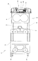
- FIG. 3 this figure is a plan view showing a state in which the moving body is accommodated.
- FIG. 6 this figure is a plan view showing a state in which the knob is prevented from rotating.
- FIG. 1 this figure is a side view showing a locked state.
- FIG. 1 this figure is a side view showing the unlocked state.
- FIG. 1 is a side view of the locking device in a state where the knob is prevented from rotating
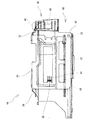
- FIG. 2 is a side view of the vehicle accessory storage device in a state in which the moving body is protruded
- FIG. 3 is a state in which the moving body is protruded
- 4 is a plan view of the accessory storage device for a vehicle
- FIG. 4 corresponds to FIG. 2 and is a side view of a state in which the moving body is stored
- FIG. 7 corresponds to FIG. 6 and is a plan view in a state where the knob is prevented from rotating
- FIG. 8 corresponds to FIG.
- FIG. 1 is a side view showing the locked state, and FIG. The side view which shows the unlocking state corresponding to each is shown.
- Vehicle accessory storage device 10 2 to 4
- reference numeral 10 denotes a vehicular accessory storage device, which is not shown, but is arranged in a vehicle interior.
- the vehicular accessory storage device 10 is an example of a lock mechanism of the moving body 30.
- the lock mechanism is not limited to the vehicular accessory storage device 10, but may be a table, a cup holder, an ashtray, or the like.
- the mounting position is not limited to the vehicle, and may be another vehicle, furniture, office equipment, or the like.
- the vehicular accessory storage device 10 is roughly divided into the following parts. The following (1) to (3) will be described later.
- housing 20 Mobile object 30 (3) Lock device 40
- the parts of the vehicular accessory storage device 10 are not limited to the above (1) to (3).
- the housing 20 has an opening 21 at least on the front surface.
- the housing 20 is an example of a base.
- the base is not limited to the housing 20.
- the housing 20 is made of metal and is formed in a box shape with front and rear surfaces opened.
- the housing 20 is fixed in the vehicle interior.
- the housing 20 includes the following parts. Each part of the housing 20 is not limited to the following (1) to (4).
- Opening 21 Although not shown, the opening 21 opens from the rear to the front of the vehicle when the housing 20 is fixed in the vehicle interior.
- Retraction position restricting part 22 The retreat position restricting portion 22 is located on the back side of the housing 20, and a pair projects inward from the left and right side surfaces. As shown in FIG. 3, the retreat position restricting unit 22 abuts on a retreat position restricting unit 54 of the moving body 30 described later, thereby restricting the last retracted position of the moving body 30.
- Elastic sliding part 23 The elastic sliding portions 23 are located on the front side of the housing 20 and elastically protrude inward from the left and right side surfaces, and the plane is bent into a substantially “V” shape or a mountain shape. As shown in FIGS. 2 and 3, the elastic sliding portion 23 gives sliding resistance to the moving body 30 by elastically slidingly contacting a guide rib 52 of the moving body 30 described later.
- the ascending restriction portion 24 is located on the back side of the housing 20, protrudes downward from the left and right sides of the upper surface, and has a plane bent into a substantially “V” shape or a mountain shape. As shown in FIGS. 2 and 3, the ascending restriction unit 24 restricts the ascent of the moving body 30 by slidingly contacting the upper edge of the moving body 30. (Moving object 30) As shown in FIGS. 2 to 5, the moving body 30 is supported so as to be movable with respect to the housing 20 as a base.
- the moving body 30 is accommodated in the housing 20 and protrudes through the opening 21.
- the moving body 30 is made of a synthetic resin and is formed in a box shape having an open top surface.
- the moving body 30 is slidably supported by the housing 20 and protrudes from the rear of the vehicle toward the front although not shown.
- the moving body 30 is slidably supported on the housing 20.
- the moving body 30 is not limited to this, and although not shown, the moving body 30 is rotatably supported on the housing 20. You may do it.
- the moving body 30 includes the following parts when roughly classified. The following (1) to (2) will be described later.
- the parts of the moving body 30 are not limited to the above (1) to (2).
- the locking device 40 locks the moving body 30 in a state of being housed in the housing 20.
- the lock device 40 includes the following parts. The following (1) to (6) will be described later.
- (1) Lock part 70 (2) Knob 80 (3) Bearing 90 (4) Cover 100 (5) Return spring 110 (6) Rotation prevention unit 120
- the parts of the locking device 40 are not limited to the above (1) to (6).
- the movable body main body 50 is formed in a box shape whose upper surface is open.
- the mobile body 50 includes the following units as shown in FIGS. Each part of the mobile body 50 is not limited to the following (1) to (4).
- the cup holder 51 2 and 4 the cup holder 51 is for holding a drinking water container (not shown) such as a cup, a can, or a ped bottle, with the mobile body 50 protruding. I testify.
- a pair of guide ribs 52 project from the left and right outer surfaces of the movable body main body 50, and are formed in a plurality of rails, for example, two, along the sliding direction of the movable body main body 50. ing.
- the guide rib 52 is in sliding contact with the elastic sliding portion 23 of the housing 20 described above.
- (3) Recess 53 As shown in FIGS. 2 and 4, the concave portion 53 is formed in the middle of the length of the guide rib 52, and the elastic sliding portion 23 of the housing 20 described above is fitted therein. As shown in FIG. 2, the recess 53 has a click feeling when the elastic sliding portion 23 of the housing 20 is fitted at the position where the movable body 50 is most protruded.
- Retraction position restriction part 54 As shown in FIGS. 2 and 4, the retreat position restricting portions 54 are located on the back side of the movable body main body 50 and project as a pair from the left and right outer surfaces of the movable body main body 50. As shown in FIG. 4, the retracted position restricting portion 54 abuts against the retracted position restricting portion 22 of the housing 20 to restrict the last retracted position of the moving body 30. (Lid 60) 2 to 5, the lid 60 covers the upper part of the front surface of the moving body main body 50, and the locking device 40 is disposed between the front surface of the moving body main body 50. (Lock part 70) As shown in FIGS. 1 and 6, the lock portion 70 is for locking either the housing 20 or the moving body 30 in a state where the moving body 30 is accommodated in the housing 20.
- the lock portion 70 is provided in the opening 21 of the housing 20 as shown in FIGS. 2 to 5, and the flat surface of the metal bar is bent into a substantially “U” shape as shown in FIG. As shown in FIG. 2, when viewed from the side, it is formed in a shape bent in an “L” shape downward.
- the knob 80 As shown in FIGS. 1 and 6, the knob 80 is rotatably supported by either the housing 20 or the moving body 30, and is engaged with the lock portion 70 at one end across the rotation shaft 81.
- the part 82 and the other end part have an operation part 83 that can be released from the locked state of the engaging part 82 that is locked by being locked by the lock part 70 by rotating.
- the rotation shaft 81 is rotatably supported by the moving body 30 via a bearing 90 described later.
- the locking portion 82 extends upward from the rotation shaft 81 and is formed in a hook shape that is hooked on the rod-shaped lock portion 70 of the housing 20.
- the operation portion 83 extends downward from the rotary shaft 81 and protrudes downward from the lid 60 described above. Although not shown, the operation portion 83 can be pulled forward by hooking a finger. .
- the present invention is not limited to this, but the knob 80 is rotated to the housing 20 although not illustrated.
- the lock part 70 may be provided on the moving body 30 so as to be supported. (Bearing part 90) As shown in FIG. 6, the bearing portions 90 project in pairs from the left and right sides of the front surface of the movable body 50 toward the near side, and support both ends of the rotary shaft 81 of the knob 80 in a rotatable manner.
- the bearing portion 90 includes the following portions. Each part of the bearing 90 is not limited to the following (1) to (2).
- (1) Circular hole 91 As shown in FIGS. 1 and 6, the circular hole 91 is formed on one side of the bearing portion 90 and rotatably supports one end portion of the rotary shaft 81 of the knob 80.
- the circular hole 91 is formed in a “U” -shaped cross section having an opening on the front side, and is formed into a substantially circular shape by closing the opening end with a cover 100 described later.
- (2) Long hole 92 The long hole 92 is formed on the other side of the bearing portion 90 as shown in FIGS. 1 and 6, and the other end portion of the rotary shaft 81 is moved by the moving body 30 as shown in FIGS. 1 and 7. It is for supporting so that a movement along a direction, ie, a slide direction, is possible.
- the long hole 92 is formed in a cross-sectional “U” shape with an opening on the front side, and is formed into a substantially oval shape by closing the opening end with a cover 100 described later. .
- the present invention is not limited to this, and the elongated holes 92 are formed on both sides of the bearing portion 90. You may make it form.
- the cover 100 covers the front side of the bearing portions 90 on both sides, thereby preventing the rotary shaft 81 of the knob 80 from coming off from the bearing portions 90.
- the return spring 110 is for urging the locking portion 82 in a direction in which it is hooked on the lock portion 70.
- a string spring is used as the return spring 110, and one end of the return spring 110 is hooked on the moving body 30 and the other end is hooked on the knob 80, and the rotating shaft 81 in FIG. Is given a clockwise rotational force.
- the return spring 110 also serves as a biasing means.
- the urging means is for urging the other end portion of the rotating shaft 81 fitted in the elongated hole 92 toward a position on the near side of the elongated hole 92.
- the return spring 110 and the urging means are combined, it is not limited to this and may be provided independently.
- the rotation preventing portion 120 has the other end portion of the rotating shaft 81 fitted in the elongated hole 92 against the urging force of the return spring 110 that also serves as the urging means. This is to prevent the knob 80 from rotating when moved toward the inner side of the long hole 92.
- the rotation prevention unit 120 abuts on the locking unit 82. That is, the rotation prevention unit 120 is not shown, but the front edge on the labor side of the moving body 50 is notched concavely from the upper edge downward, and the width of the notch is set to the locking portion 82 of the knob 80. It is set to more than the width of. And the rotation prevention part 120 is preventing rotation of the knob 80 because the bottom of a concave notch contact
- the rotation prevention part 120 contact
- the rotation preventing unit 120 is formed by cutting out the moving body main body 50, the present invention is not limited thereto, and may be a separate component from the moving body main body 50. (how to use) A method of using the vehicular accessory storage device 10 having the above-described configuration will be described.
- the moving body 30 is locked in the stored state by the lock device 40. That is, as shown in FIGS. 6 and 8, the hook-shaped locking portion 82 of the knob 80 is hooked on the rod-shaped locking portion 70 of the housing 20.
- the lock state of the locking device 40 is released, and the mobile body 30 may be pulled out from the housing 20 to the front.
- the locking portion 82 of the knob 80 fits into the concave rotation prevention portion 120 of the housing 20, and the bottom of the concave notch of the locking portion 82 is locked to the knob 80 as shown in FIG.
- the rotation of the knob 80 is prevented and the locked state of the locking device 40 is maintained.
- the return spring 110 that also serves as the urging means, as shown in FIGS. It moves toward the near side of the long hole 92 by the force.
Abstract
ロック機構(例えば車両用小物収納装置)には、ベース(例えばハウジング)、移動体、ロック装置を備える。ロック装置には、ロック部、ノブ、復帰バネ、回転軸の少なくとも一端部を、移動体の移動方向(例えばスライド方向)に沿って移動可能に支持するための長穴、回転軸の一端部を、長穴の手前側の位置に向かって付勢するための付勢手段(例えば復帰バネが兼用)、付勢手段(例えば復帰バネが兼用)の付勢力に抗して、回転軸の一端部が、長穴の奥側に向かって移動した際に、ノブの回転を阻止するための回転阻止部を備える。
Description
この発明は、移動体のロック機構に関し、例えば車室内に取り付けられた場合には、急停車時や衝突時に移動体が不用意に移動して突出するのを未然に防止することができるようにしたものである。
従来、グローブボックスやそのロック解除用のノブに衝撃が加わった際に、ロック状態が解除し、グローブボックスが開放してしまうことを防止するための各種の機構が提案されていた(例えば特許文献1~3参照)。
例えば、ノブが衝撃により押された際に、ノブから突出する突起部が、ロック本体の凹溝にはまり込み、ノブの回転を阻止している(特許文献1の段落番号「0017」、図4参照)。
例えば、ノブが衝撃により押された際に、ノブから突出する突起部が、ロック本体の凹溝にはまり込み、ノブの回転を阻止している(特許文献1の段落番号「0017」、図4参照)。
また、グローブボックスに衝撃が加わった際に、ストッパが変形してロック部を挟持することで、ロック部の回転を阻止している(特許文献2の8頁3~15頁、第4図)。
さらに、車両の衝突時に、インストルメントパネルが変形した際に、ストッパ部によりフックの回転を阻止している(特許文献3の段落番号「0017」~「0018」、図4参照)。
さらに、車両の衝突時に、インストルメントパネルが変形した際に、ストッパ部によりフックの回転を阻止している(特許文献3の段落番号「0017」~「0018」、図4参照)。
しかし、上記した従来の機構はいずれも、衝突時の衝撃がグローブボックスを閉じる方向に作用した場合を想定していたので、急停車時や衝突時に移動体が慣性力により突出しようとし、その際にロックが解除するのを防止できないという問題点があった。
そこで、本発明は、上記した従来の技術の有する問題点に鑑みてなされたものであり、その目的とするところは、次の点にある。
そこで、本発明は、上記した従来の技術の有する問題点に鑑みてなされたものであり、その目的とするところは、次の点にある。
すなわち、本発明は、慣性力等の作用によりロック状態が解除され、移動体が不用意に移動するのを未然に防止することができるようにしたものである。
例えば車室内に取り付けた場合には、急停車時や衝突時に移動体が不用意に移動して突出するのを未然に防止することができるようにする。
例えば車室内に取り付けた場合には、急停車時や衝突時に移動体が不用意に移動して突出するのを未然に防止することができるようにする。
本発明は、次の点を特徴とする。
第1に、ロック機構(例えば車両用小物収納装置)には、次の構成を備える。
なお、ロック機構として、車両用小物収納装置を例示したが、これに限定されず、テーブル、カップホルダー、灰皿等でも良く、又、取付位置も車両に限定されず、他の乗り物や、家具や事務機器等でも良い。
なお、ロック機構として、車両用小物収納装置を例示したが、これに限定されず、テーブル、カップホルダー、灰皿等でも良く、又、取付位置も車両に限定されず、他の乗り物や、家具や事務機器等でも良い。
(1)ベース(例えばハウジング)
なお、ベースとして、ハウジングを例示したが、これに限定されない。
(2)移動体
移動体は、ベース(例えばハウジング)に対して移動可能に支持されるものである。
なお、ベースとして、ハウジングを例示したが、これに限定されない。
(2)移動体
移動体は、ベース(例えばハウジング)に対して移動可能に支持されるものである。
(3)ロック装置
ロック装置は、ベース(例えばハウジング)と移動体との間に配置され、移動体をロックするためのものである。
第2に、ロック装置には、次の構成を備える。
(4)ロック部
ロック部は、ベース(例えばハウジング)と移動体とのいずれか一方(例えばハウジング)に設けられ、移動体がベース(例えばハウジング)に収納された状態にロックするためのものである。
ロック装置は、ベース(例えばハウジング)と移動体との間に配置され、移動体をロックするためのものである。
第2に、ロック装置には、次の構成を備える。
(4)ロック部
ロック部は、ベース(例えばハウジング)と移動体とのいずれか一方(例えばハウジング)に設けられ、移動体がベース(例えばハウジング)に収納された状態にロックするためのものである。
(5)ノブ
ノブは、ベース(例えばハウジング)と移動体とのいずれか他方(例えば移動体)に回転可能に支持され、当該回転軸をはさんで一端部にロック部に引っ掛かる係止部、及び他端部には回転することにより、ロック部に引っ掛かってロックされていた係止部のロック状態を解除可能な操作部を有するものである。
ノブは、ベース(例えばハウジング)と移動体とのいずれか他方(例えば移動体)に回転可能に支持され、当該回転軸をはさんで一端部にロック部に引っ掛かる係止部、及び他端部には回転することにより、ロック部に引っ掛かってロックされていた係止部のロック状態を解除可能な操作部を有するものである。
なお、ベース(例えばハウジング)に、ロック部を設け、移動体にノブを回転可能に支持したが、これに限定されず、図示しないが、逆にベース(例えばハウジング)にノブを回転可能に支持し、移動体にロック部を設けても良い。
(6)復帰バネ
復帰バネは、ロック部に引っ掛かる方向に向かって係止部を付勢するためのものである。
(6)復帰バネ
復帰バネは、ロック部に引っ掛かる方向に向かって係止部を付勢するためのものである。
第3に、ロック装置には、次の構成を備える。
(7)長穴
長穴は、回転軸の少なくとも一端部を、移動体の移動方向(例えばスライド方向)に沿って移動可能に支持するためのものである。
(7)長穴
長穴は、回転軸の少なくとも一端部を、移動体の移動方向(例えばスライド方向)に沿って移動可能に支持するためのものである。
(8)付勢手段(例えば復帰バネが兼用)
付勢手段(例えば復帰バネが兼用)は、例えば図6に示すように、回転軸の一端部を、長穴の手前側の位置に向かって付勢するためのものである。
(9)回転阻止部
回転阻止部は、付勢手段(例えば復帰バネが兼用)の付勢力に抗して、回転軸の一端部が、長穴の奥側に向かって移動した際に、ノブの回転を阻止するためのものである。
付勢手段(例えば復帰バネが兼用)は、例えば図6に示すように、回転軸の一端部を、長穴の手前側の位置に向かって付勢するためのものである。
(9)回転阻止部
回転阻止部は、付勢手段(例えば復帰バネが兼用)の付勢力に抗して、回転軸の一端部が、長穴の奥側に向かって移動した際に、ノブの回転を阻止するためのものである。
復帰バネは、付勢手段(例えば復帰バネが兼用)を兼ねてもよい。
こうすると、復帰バネと付勢手段とを兼用することで、部品点数や組立工程数を減少することができる。
回転阻止部は、係止部に当接するようにしてもよい。
こうすると、比較的に剛性の高い係止部を回転阻止部に当接させることで、ノブの破損を防止することができる。
本発明によるロック機構は、次のように構成されていてもよい。
本発明によるロック機構は、次のように構成されていてもよい。
第1に、移動体は、車両(図示せず)の後方から前方に突出するように配置されている。
第2に、係止部がロック部にロックされた状態において、移動体が突出する方向に移動しようとする際に、回転軸の一端部が長穴の奥側に向かって移動するようにしている。
第2に、係止部がロック部にロックされた状態において、移動体が突出する方向に移動しようとする際に、回転軸の一端部が長穴の奥側に向かって移動するようにしている。
こうすると、移動体が車両の後方から前方に向かって不用意に突出するのを防止することができる。
本発明は、以上のように構成されているので、以下に記載されるような効果を奏する。
慣性力等の作用によりロック状態が解除され、移動体が不用意に移動するのを未然に防止することができる。
慣性力等の作用によりロック状態が解除され、移動体が不用意に移動するのを未然に防止することができる。
例えば車室内に取り付けた場合には、急停車時や衝突時に移動体が不用意に移動して突出するのを未然に防止することができる。
(図面の説明)
図1~9は、本発明の実施の形態の一例をそれぞれ示すものである。
図1は、ノブの回転が阻止された状態のロック装置の側面図、図2は移動体を突出させた状態の車両用小物収納装置の側面図、図3は移動体を突出させた状態の車両用小物収納装置の平面図、図4は図2に対応し、移動体を収納させた状態の側面図、図5は図3に対応し、移動体を収納させた状態の平面図、図6はロック装置の平面図、図7は図6に対応し、ノブの回転が阻止された状態の平面図、図8は図1に対応し、ロック状態を示す側面図、図9は図1に対応し、ロックの解除状態を示す側面図をそれぞれ示すものである。
(車両用小物収納装置10)
図2~4中、10は、車両用小物収納装置を示すものであり、図示しないが、車室内に配置される。
上記車両用小物収納装置10は、移動体30のロック機構の一例である。ロック機構は、車両用小物収納装置10に限定されず、テーブル、カップホルダー、灰皿等でも良く、又、取付位置も車両に限定されず、他の乗り物や、家具や事務機器等でも良い。
車両用小物収納装置10は、図2~5に示すように、大別すると、次のパーツを備える。
なお、次の(1)~(3)については、後述する。
車両用小物収納装置10は、図2~5に示すように、大別すると、次のパーツを備える。
なお、次の(1)~(3)については、後述する。
(1)ハウジング20
(2)移動体30
(3)ロック装置40
なお、車両用小物収納装置10のパーツは、上記した(1)~(3)に限定されない。
(ハウジング20)
ハウジング20は、図2及び図4に示すように、少なくとも前面に開口部21を有するものである。
(2)移動体30
(3)ロック装置40
なお、車両用小物収納装置10のパーツは、上記した(1)~(3)に限定されない。
(ハウジング20)
ハウジング20は、図2及び図4に示すように、少なくとも前面に開口部21を有するものである。
上記ハウジング20は、ベースの一例である。ベースは、ハウジング20に限定されない。
具体的には、ハウジング20は、金属製で、前後面が開口した箱形に形成されている。ハウジング20は、図示しないが、車室内に固定されている。
一方、ハウジング20には、次の各部を備える。
なお、ハウジング20の各部は、次の(1)~(4)に限定されない。
具体的には、ハウジング20は、金属製で、前後面が開口した箱形に形成されている。ハウジング20は、図示しないが、車室内に固定されている。
一方、ハウジング20には、次の各部を備える。
なお、ハウジング20の各部は、次の(1)~(4)に限定されない。
(1)開口部21
開口部21は、図示しないが、車室内にハウジング20を固定した際に、車両の後方から前方に向かって開口する。
(2)後退位置規制部22
後退位置規制部22は、ハウジング20の奥側に位置し、左右の側面から内側に向かって一対突出する。後退位置規制部22は、図3に示すように、後述する移動体30の後退位置規制部54に当接することで、移動体30の最後退位置を規制している。
開口部21は、図示しないが、車室内にハウジング20を固定した際に、車両の後方から前方に向かって開口する。
(2)後退位置規制部22
後退位置規制部22は、ハウジング20の奥側に位置し、左右の側面から内側に向かって一対突出する。後退位置規制部22は、図3に示すように、後述する移動体30の後退位置規制部54に当接することで、移動体30の最後退位置を規制している。
(3)弾性摺動部23
弾性摺動部23は、ハウジング20の手前側に位置し、左右の側面から内側に向かって弾性的に一対突出し、平面が略「V」字形、或いは山形に折れ曲がっている。弾性摺動部23は、図2及び図3に示すように、後述する移動体30のガイドリブ52に弾性的に摺接することで、移動体30に摺動抵抗を付与している。
弾性摺動部23は、ハウジング20の手前側に位置し、左右の側面から内側に向かって弾性的に一対突出し、平面が略「V」字形、或いは山形に折れ曲がっている。弾性摺動部23は、図2及び図3に示すように、後述する移動体30のガイドリブ52に弾性的に摺接することで、移動体30に摺動抵抗を付与している。
(4)上昇規制部24
上昇規制部24は、ハウジング20の奥側に位置し、上面の左右両側から下方に向かって一対突出し、平面が略「V」字形、或いは山形に折れ曲がっている。上昇規制部24は、図2及び図3に示すように、移動体30の上縁に摺接することで、移動体30の上昇を規制している。
(移動体30)
移動体30は、図2~5に示すように、ベースであるハウジング20に対して移動可能に支持されるものである。
上昇規制部24は、ハウジング20の奥側に位置し、上面の左右両側から下方に向かって一対突出し、平面が略「V」字形、或いは山形に折れ曲がっている。上昇規制部24は、図2及び図3に示すように、移動体30の上縁に摺接することで、移動体30の上昇を規制している。
(移動体30)
移動体30は、図2~5に示すように、ベースであるハウジング20に対して移動可能に支持されるものである。
すなわち、移動体30は、ハウジング20に収納され、開口部21を通して突出するものである。
具体的には、移動体30は、合成樹脂製で、上面が開口した箱形に形成されている。そして、移動体30は、ハウジング20にスライド可能に支持され、図示しないが、車両の後方から前方に向かって突出する。
具体的には、移動体30は、合成樹脂製で、上面が開口した箱形に形成されている。そして、移動体30は、ハウジング20にスライド可能に支持され、図示しないが、車両の後方から前方に向かって突出する。
なお、移動体30を、図2及び図4に示すように、ハウジング20にスライド可能に支持しているが、これに限定されず、図示しないが、移動体30をハウジング20に回転可能に支持しても良い。
一方、移動体30には、大別すると、次のパーツを備える。
なお、次の(1)~(2)については、後述する。
一方、移動体30には、大別すると、次のパーツを備える。
なお、次の(1)~(2)については、後述する。
(1)移動体本体50
(2)リッド60
なお、移動体30のパーツは、上記した(1)~(2)に限定されない。
(ロック装置40)
ロック装置40は、図1及び図6に示すように、ベースであるハウジング20と移動体30との間に配置され、移動体30をロックするためのものである。
(2)リッド60
なお、移動体30のパーツは、上記した(1)~(2)に限定されない。
(ロック装置40)
ロック装置40は、図1及び図6に示すように、ベースであるハウジング20と移動体30との間に配置され、移動体30をロックするためのものである。
本実施の形態では、ロック装置40は、移動体30をハウジング20に収納された状態にロックしている。
具体的には、ロック装置40には、次のパーツを備える。
なお、次の(1)~(6)については、後述する。
(1)ロック部70
(2)ノブ80
(3)軸受部90
(4)カバー100
(5)復帰バネ110
(6)回転阻止部120
なお、ロック装置40のパーツは、上記した(1)~(6)に限定されない。
(移動体本体50)
移動体本体50は、上面が開口した箱形に形成されている。
具体的には、ロック装置40には、次のパーツを備える。
なお、次の(1)~(6)については、後述する。
(1)ロック部70
(2)ノブ80
(3)軸受部90
(4)カバー100
(5)復帰バネ110
(6)回転阻止部120
なお、ロック装置40のパーツは、上記した(1)~(6)に限定されない。
(移動体本体50)
移動体本体50は、上面が開口した箱形に形成されている。
具体的には、移動体本体50には、図2~6に示すように、次の各部を備える。
なお、移動体本体50の各部は、次の(1)~(4)に限定されない。
(1)カップホルダー51
カップホルダー51は、図2及び図4に示すように、カップや缶、ペッドボトル等の飲料水の容器(図示せず)を保持するためのものであり、移動体本体50を突出させた状態で証する。
なお、移動体本体50の各部は、次の(1)~(4)に限定されない。
(1)カップホルダー51
カップホルダー51は、図2及び図4に示すように、カップや缶、ペッドボトル等の飲料水の容器(図示せず)を保持するためのものであり、移動体本体50を突出させた状態で証する。
(2)ガイドリブ52
ガイドリブ52は、図2及び図4に示すように、移動体本体50の左右の外側面からそれぞれ一対突出し、レール状に複数条、例えば2条、移動体本体50のスライド方向に沿って形成されている。ガイドリブ52は、前述したハウジング20の弾性摺動部23と摺接する。
(3)凹部53
凹部53は、図2及び図4に示すように、ガイドリブ52の長さの途中に形成され、前述したハウジング20の弾性摺動部23がはまり込むものである。凹部53は、図2に示すように、移動体本体50を最も突出させた位置において、ハウジング20の弾性摺動部23がはまり込むことで、クリック感を持たせている。
ガイドリブ52は、図2及び図4に示すように、移動体本体50の左右の外側面からそれぞれ一対突出し、レール状に複数条、例えば2条、移動体本体50のスライド方向に沿って形成されている。ガイドリブ52は、前述したハウジング20の弾性摺動部23と摺接する。
(3)凹部53
凹部53は、図2及び図4に示すように、ガイドリブ52の長さの途中に形成され、前述したハウジング20の弾性摺動部23がはまり込むものである。凹部53は、図2に示すように、移動体本体50を最も突出させた位置において、ハウジング20の弾性摺動部23がはまり込むことで、クリック感を持たせている。
(4)後退位置規制部54
後退位置規制部54は、図2及び図4に示すように、移動体本体50の奥側に位置し、移動体本体50の左右の外側面からそれぞれ一対突出する。後退位置規制部54は、図4に示すように、ハウジング20の後退位置規制部22に当接することで、移動体30の最後退位置を規制している。
(リッド60)
リッド60は、図2~5に示すように、移動体本体50の前面の上部を覆うものであり、移動体本体50の前面との間にロック装置40を配置している。
(ロック部70)
ロック部70は、図1及び図6に示すように、ハウジング20と移動体30とのいずれか一方、移動体30がハウジング20に収納された状態にロックするためのものである。
後退位置規制部54は、図2及び図4に示すように、移動体本体50の奥側に位置し、移動体本体50の左右の外側面からそれぞれ一対突出する。後退位置規制部54は、図4に示すように、ハウジング20の後退位置規制部22に当接することで、移動体30の最後退位置を規制している。
(リッド60)
リッド60は、図2~5に示すように、移動体本体50の前面の上部を覆うものであり、移動体本体50の前面との間にロック装置40を配置している。
(ロック部70)
ロック部70は、図1及び図6に示すように、ハウジング20と移動体30とのいずれか一方、移動体30がハウジング20に収納された状態にロックするためのものである。
具体的には、ロック部70は、図2~5に示すように、ハウジング20の開口部21に設けられ、図4に示すように、金属棒を平面が略「コ」字形に折れ曲げた形状に形成され、図2に示すように、側面から見ると下方に向かって「L」字形に折れ曲げた形状に形成されている。
(ノブ80)
ノブ80は、図1及び図6に示すように、ハウジング20と移動体30とのいずれか他方に回転可能に支持され、当該回転軸81をはさんで一端部にロック部70に引っ掛かる係止部82、及び他端部には回転することにより、ロック部70に引っ掛かってロックされていた係止部82のロック状態を解除可能な操作部83を有するものである。
(ノブ80)
ノブ80は、図1及び図6に示すように、ハウジング20と移動体30とのいずれか他方に回転可能に支持され、当該回転軸81をはさんで一端部にロック部70に引っ掛かる係止部82、及び他端部には回転することにより、ロック部70に引っ掛かってロックされていた係止部82のロック状態を解除可能な操作部83を有するものである。
具体的には、回転軸81は、図1及び図6に示すように、後述する軸受部90を介して移動体30に回転可能に支持されている。
係止部82は、図1及び図6に示すように、回転軸81から上方に向かって延び、ハウジング20の棒状のロック部70に引っ掛かるフック型に形成されている。
操作部83は、図1及び図6に示すように、回転軸81から下方に向かって延び、前述したリッド60から下方に突出し、図示しないが、指を引っ掛けて手前に引っ張れるようになっている。
係止部82は、図1及び図6に示すように、回転軸81から上方に向かって延び、ハウジング20の棒状のロック部70に引っ掛かるフック型に形成されている。
操作部83は、図1及び図6に示すように、回転軸81から下方に向かって延び、前述したリッド60から下方に突出し、図示しないが、指を引っ掛けて手前に引っ張れるようになっている。
なお、ノブ80の回転軸81を、移動体30に回転可能に支持し、前述したロック部70をハウジング20に設けたが、これに限定されず、図示しないが、ノブ80をハウジング20に回転可能に支持し、ロック部70を移動体30に設けても良い。
(軸受部90)
軸受部90は、図6に示すように、移動体本体50の前面の左右から手前側に向かって一対突出し、ノブ80の回転軸81の両端部を回転可能に支持するためのものである。
(軸受部90)
軸受部90は、図6に示すように、移動体本体50の前面の左右から手前側に向かって一対突出し、ノブ80の回転軸81の両端部を回転可能に支持するためのものである。
具体的には、軸受部90には、図1及び図6に示すように、次の各部を有する。
なお、軸受部90の各部は、次の(1)~(2)に限定されない。
(1)円形穴91
円形穴91は、図1及び図6に示すように、軸受部90の一方の片側に形成され、ノブ80の回転軸81の一端部を回転可能に支持するためのものである。
なお、軸受部90の各部は、次の(1)~(2)に限定されない。
(1)円形穴91
円形穴91は、図1及び図6に示すように、軸受部90の一方の片側に形成され、ノブ80の回転軸81の一端部を回転可能に支持するためのものである。
具体的には、円形穴91は、手前側が開口した断面「U」字形に形成され、開口端を後述するカバー100により塞ぐことで、略円形に成すものである。
(2)長穴92
長穴92は、図1及び図6に示すように、軸受部90の他方の片側に形成され、図1及び図7に示すように、回転軸81の他端部を、移動体30の移動方向、すなわちスライド方向に沿って移動可能に支持するためのものである。
(2)長穴92
長穴92は、図1及び図6に示すように、軸受部90の他方の片側に形成され、図1及び図7に示すように、回転軸81の他端部を、移動体30の移動方向、すなわちスライド方向に沿って移動可能に支持するためのものである。
そして、係止部82がロック部70にロックされた状態において、移動体30が突出する方向に移動しようとする際に、図7に示すように、回転軸81の一端部が長穴92の奥側に向かって移動するようにしている。
具体的には、長穴92は、円形穴91と同様に、手前側が開口した断面「U」字形に形成され、開口端を後述するカバー100により塞ぐことで、略長円形に成すものである。
具体的には、長穴92は、円形穴91と同様に、手前側が開口した断面「U」字形に形成され、開口端を後述するカバー100により塞ぐことで、略長円形に成すものである。
なお、軸受部90の一方の片側に、円形穴91を形成し、軸受部90の他方の片側に長穴92を形成したが、これに限定されず、軸受部90の両側に長穴92を形成するようにしても良い。
(カバー100)
カバー100は、図1及び図6に示すように、両側の軸受部90の手前側を覆うことで、軸受部90からのノブ80の回転軸81の抜けを防止するためのものであり、移動体本体50の前面に固定される。
(復帰バネ110)
復帰バネ110は、図6に示すように、ロック部70に引っ掛かる方向に向かって係止部82を付勢するためのものである。
(カバー100)
カバー100は、図1及び図6に示すように、両側の軸受部90の手前側を覆うことで、軸受部90からのノブ80の回転軸81の抜けを防止するためのものであり、移動体本体50の前面に固定される。
(復帰バネ110)
復帰バネ110は、図6に示すように、ロック部70に引っ掛かる方向に向かって係止部82を付勢するためのものである。
具体的には、復帰バネ110には、弦巻バネを使用し、その一端部を移動体30に、他端部をノブ80にそれぞれ引っ掛け、バネの復元力により図8において、回転軸81を中心に時計回りの回転力を付与している。
また、復帰バネ110が、図6に示すように、付勢手段を兼ねている。
上記付勢手段は、図6に示すように、長穴92にはまり込んでいる回転軸81の他端部を、長穴92の手前側の位置に向かって付勢するためのものである。
また、復帰バネ110が、図6に示すように、付勢手段を兼ねている。
上記付勢手段は、図6に示すように、長穴92にはまり込んでいる回転軸81の他端部を、長穴92の手前側の位置に向かって付勢するためのものである。
なお、復帰バネ110と付勢手段とを兼用したが、これに限らず、独立して設けても良い。
(回転阻止部120)
回転阻止部120は、図1及び図7に示すように、付勢手段を兼用する復帰バネ110の付勢力に抗して、長穴92にはまり込んでいる回転軸81の他端部が、長穴92の奥側に向かって移動した際に、ノブ80の回転を阻止するためのものである。
(回転阻止部120)
回転阻止部120は、図1及び図7に示すように、付勢手段を兼用する復帰バネ110の付勢力に抗して、長穴92にはまり込んでいる回転軸81の他端部が、長穴92の奥側に向かって移動した際に、ノブ80の回転を阻止するためのものである。
具体的には、回転阻止部120は、図1及び図7に示すように、係止部82に当接するようにしている。
すなわち、回転阻止部120は、図示しないが、移動体本体50の手間側の前縁を、その上縁から下方に向かって凹状の切り欠き、当該切り欠きの幅をノブ80の係止部82の横幅以上に設定している。そして、回転阻止部120は、凹状の切り欠きの底が、図1に示すように、ノブ80の係止部82に当接することで、ノブ80の回転を阻止している。
すなわち、回転阻止部120は、図示しないが、移動体本体50の手間側の前縁を、その上縁から下方に向かって凹状の切り欠き、当該切り欠きの幅をノブ80の係止部82の横幅以上に設定している。そして、回転阻止部120は、凹状の切り欠きの底が、図1に示すように、ノブ80の係止部82に当接することで、ノブ80の回転を阻止している。
なお、回転阻止部120が、ノブ80の係止部82に当接するようにしたが、これに限らず、ノブ80の操作部83が当接するようにしても良い。また、回転阻止部120を、移動体本体50を切り欠いて形成したが、これに限らず、移動体本体50と別体の部品としても良い。
(使用方法)
上記した構成を備える車両用小物収納装置10の使用方法について説明する。
(使用方法)
上記した構成を備える車両用小物収納装置10の使用方法について説明する。
まず、図3及び図5に示すように、移動体30をハウジング20内に収納した状態では、移動体30は収納状態にロック装置40によりロックされている。
すなわち、図6及び図8に示すように、ノブ80のフック状の係止部82が、ハウジング20の棒状のロック部70に引っ掛かっている。
収納状態の移動体30を突出させるには、ロック装置40のロック状態を解除し、移動体30をハウジング20から手前に引き出せば良い。
すなわち、図6及び図8に示すように、ノブ80のフック状の係止部82が、ハウジング20の棒状のロック部70に引っ掛かっている。
収納状態の移動体30を突出させるには、ロック装置40のロック状態を解除し、移動体30をハウジング20から手前に引き出せば良い。
すなわち、図9に示すように、ノブ80の操作部83に指を掛けて、手前に引っ張ると、回転軸81を中心にノブ80が回転することで、フック状の係止部82がハウジング20の棒状のロック部70から下方に係脱し、ロック装置40のロック状態が解除される。このため、ノブ80の操作部83に指を掛けたまま、移動体30を手前に引っ張ることで、図2及び図4に示すように、移動体30がハウジング20から手前側に突出する。
(ノブ80の回転の阻止状態の説明)
つぎに、ノブ80の回転の阻止状態について説明する。
(ノブ80の回転の阻止状態の説明)
つぎに、ノブ80の回転の阻止状態について説明する。
図3及び図5に示すように、移動体30をハウジング20内に収納した状態した状態で、車両が急停車や衝突すると、移動体30が慣性力により、ハウジング20から突出しようとする。
このとき、長穴92にはまり込んでいる回転軸81の他端部が、図1及び図7に示すように、付勢手段を兼用する復帰バネ110の付勢力に抗して、長穴92にはまり込んでいる回転軸81の他端部が、長穴92の奥側に向かって移動する。
このとき、長穴92にはまり込んでいる回転軸81の他端部が、図1及び図7に示すように、付勢手段を兼用する復帰バネ110の付勢力に抗して、長穴92にはまり込んでいる回転軸81の他端部が、長穴92の奥側に向かって移動する。
このため、ノブ80の係止部82が、ハウジング20の凹状の回転阻止部120にはまり込み、係止部82が凹状の切り欠きの底が、図1に示すように、ノブ80の係止部82に当接することで、ノブ80の回転が阻止され、ロック装置40のロック状態が維持される。
一方、移動体30の慣性力が無くなると、長穴92にはまり込んでいる回転軸81の他端部が、図6及び図8に示すように、付勢手段を兼用する復帰バネ110の付勢力により、長穴92の手前側に向かって移動する。
一方、移動体30の慣性力が無くなると、長穴92にはまり込んでいる回転軸81の他端部が、図6及び図8に示すように、付勢手段を兼用する復帰バネ110の付勢力により、長穴92の手前側に向かって移動する。
このとき、ハウジング20の凹状の回転阻止部120にはまり込んでいたノブ80の係止部82が、凹状の回転阻止部120から抜け出す。
このため、ロック装置40のロックの解除が、再度、可能となる。
なお、2008年11月19日に出願された日本特許出願第2008-295161号の明細書、特許請求の範囲、図面及び要約書の全内容をここに引用し、本発明の明細書の開示として、取り入れるものである。
このため、ロック装置40のロックの解除が、再度、可能となる。
なお、2008年11月19日に出願された日本特許出願第2008-295161号の明細書、特許請求の範囲、図面及び要約書の全内容をここに引用し、本発明の明細書の開示として、取り入れるものである。
Claims (4)
- ベースと、
前記ベースに対して移動可能に支持される移動体と、
前記ベースと前記移動体との間に配置され、前記移動体をロックするためのロック装置を備え、
前記ロック装置には、
前記ベースと前記移動体とのいずれか一方に設けられるロック部と、
前記ベースと前記移動体とのいずれか他方に回転可能に支持され、当該回転軸をはさんで一端部に前記ロック部に引っ掛かる係止部、及び他端部には回転することにより、前記ロック部に引っ掛かってロックされていた前記係止部のロック状態を解除可能な操作部を有するノブと、
前記ロック部に引っ掛かる方向に向かって前記係止部を付勢するための復帰バネとを備える移動体のロック機構において、
前記ロック装置には、
前記回転軸の少なくとも一端部を、前記移動体の移動方向に沿って移動可能に支持するための長穴と、
前記回転軸の一端部を、前記長穴の手前側の位置に向かって付勢するための付勢手段と、
前記付勢手段の付勢力に抗して、前記回転軸の一端部が、前記長穴の奥側に向かって移動した際に、前記ノブの回転を阻止するための回転阻止部とを備えていることを特徴とする移動体のロック機構。 - 請求項1に記載の移動体のロック機構であって、
前記復帰バネが、前記付勢手段を兼ねていることを特徴とする移動体のロック機構。 - 請求項1又は請求項2に記載の移動体のロック機構であって、
前記回転阻止部は、
前記係止部に当接するようにしていることを特徴とする移動体のロック機構。 - 請求項1~3のいずれか一方に記載の移動体のロック機構であって、
前記移動体は、
車両の後方から前方に向かって突出するように配置され、
前記係止部が前記ロック部にロックされた状態において、前記移動体が突出する方向に移動しようとする際に、前記回転軸の一端部が前記長穴の奥側に向かって移動するようにしていることを特徴とする移動体のロック機構。
Priority Applications (3)
| Application Number | Priority Date | Filing Date | Title |
|---|---|---|---|
| EP09827533.2A EP2354397B1 (en) | 2008-11-19 | 2009-11-16 | Mobile object lock mechanism |
| CN200980146283.8A CN102216548B (zh) | 2008-11-19 | 2009-11-16 | 移动体的锁定机构 |
| US12/998,661 US9080353B2 (en) | 2008-11-19 | 2009-11-16 | Lock mechanism of mobile member |
Applications Claiming Priority (2)
| Application Number | Priority Date | Filing Date | Title |
|---|---|---|---|
| JP2008295161A JP5336156B2 (ja) | 2008-11-19 | 2008-11-19 | 移動体のロック機構 |
| JP2008-295161 | 2008-11-19 |
Publications (1)
| Publication Number | Publication Date |
|---|---|
| WO2010058752A1 true WO2010058752A1 (ja) | 2010-05-27 |
Family
ID=42198192
Family Applications (1)
| Application Number | Title | Priority Date | Filing Date |
|---|---|---|---|
| PCT/JP2009/069437 WO2010058752A1 (ja) | 2008-11-19 | 2009-11-16 | 移動体のロック機構 |
Country Status (6)
| Country | Link |
|---|---|
| US (1) | US9080353B2 (ja) |
| EP (1) | EP2354397B1 (ja) |
| JP (1) | JP5336156B2 (ja) |
| KR (1) | KR101172576B1 (ja) |
| CN (1) | CN102216548B (ja) |
| WO (1) | WO2010058752A1 (ja) |
Families Citing this family (9)
| Publication number | Priority date | Publication date | Assignee | Title |
|---|---|---|---|---|
| JP5823792B2 (ja) | 2011-09-22 | 2015-11-25 | 株式会社ニフコ | ロック装置 |
| DE102013006826A1 (de) | 2013-04-22 | 2014-10-23 | Illinois Tool Works Inc. | Türgriffanordnung für ein Automobil |
| EP3087235B1 (en) * | 2013-12-23 | 2020-12-02 | Faurecia Interior Systems India Pvt. Ltd. | Locking device comprising a locking element movable in a first direction and in a second direction |
| KR20170030148A (ko) * | 2015-09-08 | 2017-03-17 | 주식회사 니프코코리아 | 콘솔박스 개폐용 후크 |
| FR3058960B1 (fr) * | 2016-11-21 | 2021-03-26 | Peugeot Citroen Automobiles Sa | Tiroir de rangement avec systeme de verrouillage et bouton poussoir |
| DE102019204698A1 (de) | 2018-04-10 | 2019-10-10 | Faurecia Innenraum Systeme Gmbh | Verriegelungsmechanismus für ein Ablagefach mit einem Deckel und Ablagefach mit entsprechendem Verriegelungsmechanismus |
| CN109051394A (zh) * | 2018-08-15 | 2018-12-21 | 四川宏华石油设备有限公司 | 一种柔性水罐锁紧装置 |
| CN109051393A (zh) * | 2018-08-15 | 2018-12-21 | 四川宏华石油设备有限公司 | 一种柔性水罐锁紧装置 |
| FR3137638A1 (fr) * | 2022-07-11 | 2024-01-12 | Psa Automobiles Sa | Boîte de rangement pour véhicule automobile comprenant un dispositif de fermeture d’un tiroir |
Citations (6)
| Publication number | Priority date | Publication date | Assignee | Title |
|---|---|---|---|---|
| JPH0276546U (ja) | 1988-11-30 | 1990-06-12 | ||
| JPH0335020Y2 (ja) * | 1985-04-28 | 1991-07-24 | ||
| JPH0547234Y2 (ja) * | 1988-03-16 | 1993-12-13 | ||
| JP2565196Y2 (ja) | 1992-02-18 | 1998-03-11 | スズキ株式会社 | グローブボックス用ロック装置 |
| JP2000110433A (ja) | 1998-10-02 | 2000-04-18 | Mitsubishi Motors Corp | グローブボックス開放防止装置 |
| JP2008295161A (ja) | 2007-05-23 | 2008-12-04 | Daikin Ind Ltd | 電力変換装置 |
Family Cites Families (19)
| Publication number | Priority date | Publication date | Assignee | Title |
|---|---|---|---|---|
| US1840037A (en) * | 1928-07-04 | 1932-01-05 | Johansson Johan Petter | Lock |
| US2029199A (en) * | 1935-04-23 | 1936-01-28 | Segar Lee | Handle |
| US2634997A (en) * | 1949-11-04 | 1953-04-14 | William R Gallowitz | Spring latch mechanism |
| US2773715A (en) * | 1954-10-22 | 1956-12-11 | Chicago Forging & Mfg Co | Hood latch |
| US4003593A (en) * | 1976-02-23 | 1977-01-18 | Herbert Wilzig | Push door-latch opener |
| JPS646482A (en) * | 1987-06-26 | 1989-01-11 | Ohi Seisakusho Co Ltd | Door lock apparatus for vehicle |
| JPH0276546A (ja) | 1988-09-12 | 1990-03-15 | Funai Electric Co Ltd | 飯 |
| JPH0628417Y2 (ja) | 1989-08-15 | 1994-08-03 | 本州製紙株式会社 | 宅配便用保冷ケース |
| JPH0547234U (ja) | 1991-07-10 | 1993-06-22 | ナショナル住宅産業株式会社 | 防水パン |
| DE4336619C1 (de) | 1993-10-27 | 1995-02-09 | Porsche Ag | Verschluß für ein Deckelelement eines Fahrzeuges, insbesondere für einen Handschuhkastendeckel eines Kraftfahrzeuges |
| US5630630A (en) * | 1995-07-11 | 1997-05-20 | Strattec Security Corporation | Glove compartment latch mechanism |
| CN2312295Y (zh) * | 1997-08-21 | 1999-03-31 | 张士忠 | 一种推拉式门把手 |
| IT1309802B1 (it) | 1999-05-07 | 2002-01-30 | Valeo Sicurezza Abitacolo Spa | Maniglia per una porta di un veicolo |
| DE19929022C2 (de) | 1999-06-25 | 2001-06-07 | Huf Huelsbeck & Fuerst Gmbh | Türaußengriff, insbesondere für Fahrzeuge |
| CN2418216Y (zh) * | 1999-12-29 | 2001-02-07 | 范芳溢 | 把手锁具 |
| DE10015887C1 (de) | 2000-03-30 | 2002-01-17 | Huf Huelsbeck & Fuerst Gmbh | Zugangssystem für ein Fahrzeug |
| JP4462768B2 (ja) * | 2001-01-19 | 2010-05-12 | 株式会社ニフコ | 安全機能付ロック装置及び乗物用収納装置 |
| US7152893B2 (en) * | 2004-08-23 | 2006-12-26 | Key Plastics, Llc | Handle assembly with dual latch feature |
| CN201027435Y (zh) * | 2007-03-27 | 2008-02-27 | 白宝鲲 | 门窗把手动作防误装置 |
-
2008
- 2008-11-19 JP JP2008295161A patent/JP5336156B2/ja active Active
-
2009
- 2009-11-16 WO PCT/JP2009/069437 patent/WO2010058752A1/ja active Application Filing
- 2009-11-16 US US12/998,661 patent/US9080353B2/en not_active Expired - Fee Related
- 2009-11-16 EP EP09827533.2A patent/EP2354397B1/en not_active Not-in-force
- 2009-11-16 CN CN200980146283.8A patent/CN102216548B/zh not_active Expired - Fee Related
- 2009-11-19 KR KR1020090111850A patent/KR101172576B1/ko active IP Right Grant
Patent Citations (6)
| Publication number | Priority date | Publication date | Assignee | Title |
|---|---|---|---|---|
| JPH0335020Y2 (ja) * | 1985-04-28 | 1991-07-24 | ||
| JPH0547234Y2 (ja) * | 1988-03-16 | 1993-12-13 | ||
| JPH0276546U (ja) | 1988-11-30 | 1990-06-12 | ||
| JP2565196Y2 (ja) | 1992-02-18 | 1998-03-11 | スズキ株式会社 | グローブボックス用ロック装置 |
| JP2000110433A (ja) | 1998-10-02 | 2000-04-18 | Mitsubishi Motors Corp | グローブボックス開放防止装置 |
| JP2008295161A (ja) | 2007-05-23 | 2008-12-04 | Daikin Ind Ltd | 電力変換装置 |
Non-Patent Citations (1)
| Title |
|---|
| See also references of EP2354397A4 * |
Also Published As
| Publication number | Publication date |
|---|---|
| CN102216548A (zh) | 2011-10-12 |
| JP2010121336A (ja) | 2010-06-03 |
| JP5336156B2 (ja) | 2013-11-06 |
| US9080353B2 (en) | 2015-07-14 |
| US20110241358A1 (en) | 2011-10-06 |
| EP2354397A1 (en) | 2011-08-10 |
| KR20100056409A (ko) | 2010-05-27 |
| KR101172576B1 (ko) | 2012-08-08 |
| EP2354397A4 (en) | 2014-10-29 |
| CN102216548B (zh) | 2014-06-04 |
| EP2354397B1 (en) | 2016-01-13 |
Similar Documents
| Publication | Publication Date | Title |
|---|---|---|
| WO2010058752A1 (ja) | 移動体のロック機構 | |
| JP4480036B2 (ja) | アームレストの取付け構造 | |
| JP5364420B2 (ja) | カップホルダ | |
| EP2010414B1 (en) | Latch system for sliding panel in vehicle | |
| US8353549B2 (en) | Push button mechanism for opening and closing a storage compartment for a vehicle | |
| US20050167300A1 (en) | Storage box | |
| JP2003276516A (ja) | ガイド機構、該ガイド機構を用いた蓋体の開閉機構、及び該開閉機構を用いた車載用内装品 | |
| US8109424B2 (en) | Tray apparatus | |
| KR101055007B1 (ko) | 덮개체의 개폐기구 및 차량용 소품상자 | |
| JP2007285025A (ja) | ロック装置 | |
| KR100973134B1 (ko) | 글러브 박스 | |
| JP4276101B2 (ja) | ゲーム機の施錠装置 | |
| US11162286B2 (en) | Closing device for a storage compartment, storage compartment for a motor vehicle | |
| JP4245528B2 (ja) | 車両用収納装置 | |
| JP2000135950A (ja) | 車両用物入れ装置 | |
| JP4170601B2 (ja) | ロック装置 | |
| KR100381482B1 (ko) | 자동차의 콘솔 록킹 장치 | |
| JP5816021B2 (ja) | 車両用カップホルダ装置 | |
| JP5508152B2 (ja) | 車両用物入れ | |
| KR100828611B1 (ko) | 차량 트레이의 잠금 구조 | |
| JP6005505B2 (ja) | ロック部構造 | |
| JP6071058B2 (ja) | リッド係止機構 | |
| JP6628627B2 (ja) | ロック構造 | |
| JP2008068638A (ja) | 車両用物入装置 | |
| JP2016203857A (ja) | グローブボックス |
Legal Events
| Date | Code | Title | Description |
|---|---|---|---|
| WWE | Wipo information: entry into national phase |
Ref document number: 200980146283.8 Country of ref document: CN |
|
| 121 | Ep: the epo has been informed by wipo that ep was designated in this application |
Ref document number: 09827533 Country of ref document: EP Kind code of ref document: A1 |
|
| NENP | Non-entry into the national phase |
Ref country code: DE |
|
| WWE | Wipo information: entry into national phase |
Ref document number: 2009827533 Country of ref document: EP |
|
| WWE | Wipo information: entry into national phase |
Ref document number: 12998661 Country of ref document: US |