WO2010058583A1 - 血漿浄化装置及び血液浄化装置の制御方法 - Google Patents
血漿浄化装置及び血液浄化装置の制御方法 Download PDFInfo
- Publication number
- WO2010058583A1 WO2010058583A1 PCT/JP2009/006235 JP2009006235W WO2010058583A1 WO 2010058583 A1 WO2010058583 A1 WO 2010058583A1 JP 2009006235 W JP2009006235 W JP 2009006235W WO 2010058583 A1 WO2010058583 A1 WO 2010058583A1
- Authority
- WO
- WIPO (PCT)
- Prior art keywords
- plasma
- blood
- circuit
- pump
- separator
- Prior art date
- Legal status (The legal status is an assumption and is not a legal conclusion. Google has not performed a legal analysis and makes no representation as to the accuracy of the status listed.)
- Ceased
Links
Images


Classifications
-
- A—HUMAN NECESSITIES
- A61—MEDICAL OR VETERINARY SCIENCE; HYGIENE
- A61M—DEVICES FOR INTRODUCING MEDIA INTO, OR ONTO, THE BODY; DEVICES FOR TRANSDUCING BODY MEDIA OR FOR TAKING MEDIA FROM THE BODY; DEVICES FOR PRODUCING OR ENDING SLEEP OR STUPOR
- A61M1/00—Suction or pumping devices for medical purposes; Devices for carrying-off, for treatment of, or for carrying-over, body-liquids; Drainage systems
- A61M1/34—Filtering material out of the blood by passing it through a membrane, i.e. hemofiltration or diafiltration
- A61M1/3472—Filtering material out of the blood by passing it through a membrane, i.e. hemofiltration or diafiltration with treatment of the filtrate
- A61M1/3482—Filtering material out of the blood by passing it through a membrane, i.e. hemofiltration or diafiltration with treatment of the filtrate by filtrating the filtrate using another cross-flow filter, e.g. a membrane filter
-
- A—HUMAN NECESSITIES
- A61—MEDICAL OR VETERINARY SCIENCE; HYGIENE
- A61M—DEVICES FOR INTRODUCING MEDIA INTO, OR ONTO, THE BODY; DEVICES FOR TRANSDUCING BODY MEDIA OR FOR TAKING MEDIA FROM THE BODY; DEVICES FOR PRODUCING OR ENDING SLEEP OR STUPOR
- A61M1/00—Suction or pumping devices for medical purposes; Devices for carrying-off, for treatment of, or for carrying-over, body-liquids; Drainage systems
- A61M1/34—Filtering material out of the blood by passing it through a membrane, i.e. hemofiltration or diafiltration
- A61M1/3472—Filtering material out of the blood by passing it through a membrane, i.e. hemofiltration or diafiltration with treatment of the filtrate
-
- A—HUMAN NECESSITIES
- A61—MEDICAL OR VETERINARY SCIENCE; HYGIENE
- A61M—DEVICES FOR INTRODUCING MEDIA INTO, OR ONTO, THE BODY; DEVICES FOR TRANSDUCING BODY MEDIA OR FOR TAKING MEDIA FROM THE BODY; DEVICES FOR PRODUCING OR ENDING SLEEP OR STUPOR
- A61M1/00—Suction or pumping devices for medical purposes; Devices for carrying-off, for treatment of, or for carrying-over, body-liquids; Drainage systems
- A61M1/34—Filtering material out of the blood by passing it through a membrane, i.e. hemofiltration or diafiltration
- A61M1/3472—Filtering material out of the blood by passing it through a membrane, i.e. hemofiltration or diafiltration with treatment of the filtrate
- A61M1/3486—Biological, chemical treatment, e.g. chemical precipitation; treatment by absorbents
-
- A—HUMAN NECESSITIES
- A61—MEDICAL OR VETERINARY SCIENCE; HYGIENE
- A61M—DEVICES FOR INTRODUCING MEDIA INTO, OR ONTO, THE BODY; DEVICES FOR TRANSDUCING BODY MEDIA OR FOR TAKING MEDIA FROM THE BODY; DEVICES FOR PRODUCING OR ENDING SLEEP OR STUPOR
- A61M1/00—Suction or pumping devices for medical purposes; Devices for carrying-off, for treatment of, or for carrying-over, body-liquids; Drainage systems
- A61M1/34—Filtering material out of the blood by passing it through a membrane, i.e. hemofiltration or diafiltration
- A61M1/3496—Plasmapheresis; Leucopheresis; Lymphopheresis
-
- A—HUMAN NECESSITIES
- A61—MEDICAL OR VETERINARY SCIENCE; HYGIENE
- A61M—DEVICES FOR INTRODUCING MEDIA INTO, OR ONTO, THE BODY; DEVICES FOR TRANSDUCING BODY MEDIA OR FOR TAKING MEDIA FROM THE BODY; DEVICES FOR PRODUCING OR ENDING SLEEP OR STUPOR
- A61M1/00—Suction or pumping devices for medical purposes; Devices for carrying-off, for treatment of, or for carrying-over, body-liquids; Drainage systems
- A61M1/36—Other treatment of blood in a by-pass of the natural circulatory system, e.g. temperature adaptation, irradiation ; Extra-corporeal blood circuits
- A61M1/3621—Extra-corporeal blood circuits
- A61M1/3643—Priming, rinsing before or after use
-
- A—HUMAN NECESSITIES
- A61—MEDICAL OR VETERINARY SCIENCE; HYGIENE
- A61M—DEVICES FOR INTRODUCING MEDIA INTO, OR ONTO, THE BODY; DEVICES FOR TRANSDUCING BODY MEDIA OR FOR TAKING MEDIA FROM THE BODY; DEVICES FOR PRODUCING OR ENDING SLEEP OR STUPOR
- A61M1/00—Suction or pumping devices for medical purposes; Devices for carrying-off, for treatment of, or for carrying-over, body-liquids; Drainage systems
- A61M1/36—Other treatment of blood in a by-pass of the natural circulatory system, e.g. temperature adaptation, irradiation ; Extra-corporeal blood circuits
- A61M1/3621—Extra-corporeal blood circuits
- A61M1/3643—Priming, rinsing before or after use
- A61M1/3644—Mode of operation
- A61M1/3646—Expelling the residual body fluid after use, e.g. back to the body
-
- A—HUMAN NECESSITIES
- A61—MEDICAL OR VETERINARY SCIENCE; HYGIENE
- A61M—DEVICES FOR INTRODUCING MEDIA INTO, OR ONTO, THE BODY; DEVICES FOR TRANSDUCING BODY MEDIA OR FOR TAKING MEDIA FROM THE BODY; DEVICES FOR PRODUCING OR ENDING SLEEP OR STUPOR
- A61M1/00—Suction or pumping devices for medical purposes; Devices for carrying-off, for treatment of, or for carrying-over, body-liquids; Drainage systems
- A61M1/36—Other treatment of blood in a by-pass of the natural circulatory system, e.g. temperature adaptation, irradiation ; Extra-corporeal blood circuits
- A61M1/3621—Extra-corporeal blood circuits
- A61M1/3643—Priming, rinsing before or after use
- A61M1/3644—Mode of operation
- A61M1/365—Mode of operation through membranes, e.g. by inverted trans-membrane pressure [TMP]
-
- A—HUMAN NECESSITIES
- A61—MEDICAL OR VETERINARY SCIENCE; HYGIENE
- A61M—DEVICES FOR INTRODUCING MEDIA INTO, OR ONTO, THE BODY; DEVICES FOR TRANSDUCING BODY MEDIA OR FOR TAKING MEDIA FROM THE BODY; DEVICES FOR PRODUCING OR ENDING SLEEP OR STUPOR
- A61M1/00—Suction or pumping devices for medical purposes; Devices for carrying-off, for treatment of, or for carrying-over, body-liquids; Drainage systems
- A61M1/36—Other treatment of blood in a by-pass of the natural circulatory system, e.g. temperature adaptation, irradiation ; Extra-corporeal blood circuits
- A61M1/3621—Extra-corporeal blood circuits
- A61M1/3643—Priming, rinsing before or after use
- A61M1/3644—Mode of operation
- A61M1/3652—Mode of operation using gas, e.g. air
Definitions
- the present invention relates to a plasma purification apparatus and a blood purification apparatus control method.
- a plasma purification apparatus that performs plasma purification therapy such as plasma component separation or plasma adsorption has a blood collection circuit, a blood return circuit, a plasma circuit, a plasma separator, a plasma component separator, or a plasma adsorber.
- plasma component separation or plasma adsorption When the plasma component separation or plasma adsorption is completed, blood remains in the blood side space of the blood collection circuit, the blood return circuit, and the plasma separator, and the blood remains in the filtration side space of the plasma separator, the plasma circuit, the plasma component separator, or the plasma adsorber. Plasma remains. Since blood and plasma remaining in the aforementioned circuit, plasma separator, plasma component separator or plasma adsorber are useful components, they are generally returned to the patient after plasma purification therapy.
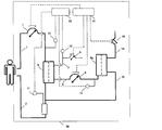
- FIG. 3 shows a configuration example of a plasma component separation device 50 according to an embodiment of Patent Document 1.
- the plasma component separator 50 includes a plasma separator 5 and a plasma component separator 6a.
- a blood collection circuit 1 is connected to the blood inlet of the plasma separator 5, and a blood pump 7 is disposed in the blood collection circuit 1. Between the blood pump 7 and the plasma separator 5, the first pressure measuring means 10 is disposed.
- a blood return circuit 2 is connected to the blood outlet of the plasma separator 5, and the second pressure measuring means 11 is disposed in the blood return circuit 2.
- the first pressure measuring circuit 3 is connected to the first filtration outlet of the plasma separator 5, the plasma circuit 4 is connected to the second filtration outlet, and the plasma circuit 4 is connected to the plasma component separator 6a.
- a plasma pump 8 is arranged in the plasma circuit 4.
- a third pressure measuring means 12 and a branch pipe are arranged, and a second valve 21 is arranged in the branch pipe.
- a return circuit 15 is connected to the first plasma component outlet of the plasma component separator 6a.
- the return circuit 15 is connected to the blood return circuit 2, and the first valve 20 is disposed upstream of the junction between the return circuit 15 and the blood return circuit 2.
- the plasma component separation device 50 further includes a calculation unit 30 and a control unit 31.
- the calculation means 30 and the control means 31 are connected.
- the calculation means 30 is connected to the first pressure measurement means 10, the second pressure measurement means 11, and the third pressure measurement means 12, and the control means 31 is blood.
- the pump 7, the plasma pump 8, the first valve 20, and the second valve 21 are connected.
- the blood side space of the blood collection circuit 1, the blood return circuit 2, and the plasma separator 5 is filled with blood. Further, the filtration side space of the plasma separator 5, the plasma circuit 4, the plasma component separator 6a, and the return circuit 15 are filled with plasma.
- the blood collection circuit 1 and the blood return circuit 2 remain connected to the patient, and the blood pump 7 remains in operation. First, the blood pump 7 is temporarily stopped, and the blood collection circuit 1 is removed from the human body. Connect to recovery saline.
- the blood collection circuit 1 When the blood collection circuit 1 is connected to the physiological saline for collection, the operation of the blood pump 7 is resumed, and the blood of the blood collection circuit 1, the plasma separator 5 and the blood return circuit 2 is collected. At this time, since the plasma pump 8 is stopped while the plasma side of the plasma separator 5, the plasma circuit 4, the plasma component separator 6 a and the return circuit 15 are filled with plasma, it takes time to collect blood. If this happens, the plasma may clot.
- the blood pump 7 is stopped, the first valve 20 is closed, the second valve 21 is opened, the plasma pump 8 is operated, the filtration side space of the plasma separator 5, the plasma circuit 4, and the plasma component separator 6a. Then, the plasma of the reversion circuit 15 is collected. At this time, since the blood pump 7 is stopped, there is a risk of blood coagulation if the blood is not collected as described above. When plasma collection is complete, remove the blood return circuit from the human body.
- the plasma pump 8 is stopped while the blood is recovered. Therefore, the plasma component separator 6a or the plasma adsorber 6b is clogged, and then the plasma pump 8 is operated. However, plasma could not be recovered. Even if the plasma is collected first and the blood is collected later, the blood in the blood collection circuit 1, the blood return circuit 2, and the plasma separator 5 is still used because the blood pump 7 is stopped when the plasma is collected. Blood may clot in the side space.
- the flow rate of the blood pump is about 100 mL / min, and the amount of blood remaining in the blood side space of the blood collection circuit, the blood return circuit, and the plasma separator is about 200 mL, so that blood collection is completed in about 2 minutes.
- the flow rate of the plasma pump is too early, it clogs the plasma component separator or the plasma adsorber, and is about 20 mL / min. Since about 200 mL of plasma remains in the filtration side space of the plasma separator, the plasma circuit, the plasma component separator or the plasma adsorber, the plasma recovery takes about 10 minutes. For this reason, there was a problem that the time required for the two-person work was increased.
- An object of the present invention is to provide a plasma purification apparatus that can easily collect blood and plasma remaining in the plasma purification apparatus after completion of the plasma purification therapy, without fear of coagulation, in view of the above-mentioned problems of the prior art. There is.
- the present inventor has been able to separate plasma by using the characteristics of a filtration membrane such as a hollow fiber that does not allow air to pass through once it is wetted with a liquid such as blood or physiological saline.
- the present inventors have found that the plasma remaining in the filtration side space of the vessel can be recovered and have reached the present invention. That is, the present invention relates to the following.
- a plasma separator having a blood collection circuit at the blood inlet, a blood return circuit at the blood outlet, a first pressure measuring circuit at the first filtration outlet, and a plasma circuit at the second filtration outlet;
- a plasma purification apparatus having a plasma component separator or a plasma adsorber each having a plasma component separator or a plasma adsorber connected to the plasma circuit and a plasma outlet, respectively, to a blood return circuit that communicates with the blood return circuit.
- the flow rate of the air pump and the plasma pump is controlled so that the pressure in the side space is higher than the pressure in the blood side space, and the plasma remaining in the filtration side space of the plasma separator is removed from the air from the air pump.
- a control means for supplying the blood to a blood side space or a plasma circuit of the plasma separator by supply.
- the control means continues to operate the blood pump, while the pressure in the blood side space is higher than the filtration side space.
- the flow rate of the plasma pump and the air pump is controlled so that the difference from the pressure of the plasma is equal to or less than a preset reference value, and the plasma in the plasma circuit is sent to the plasma component separator or plasma adsorber
- the plasma purification apparatus according to (i).
- the plasma purification apparatus includes a first pressure measuring unit that measures the pressure P1 of the blood collection circuit, a second pressure measuring unit that measures the pressure P2 of the blood return circuit, and the first pressure measurement.
- Third pressure measuring means for measuring the circuit pressure P3, and the transmembrane pressure difference TMP defined by any one of the formulas (1) and (2) is calculated from the pressures P1, P2, and P3.
- Arithmetic means, and the control means controls the flow rates of the plasma pump and the air pump so that the transmembrane pressure difference TMP falls within a predetermined negative pressure range, and plasma in the plasma circuit Is sent to the plasma component separator or plasma adsorber, the plasma purification apparatus according to (ii).
- the control means adjusts the flow rate of the air pump so that the flow rate of the air pump becomes larger than the flow rate of the plasma pump when the transmembrane pressure difference TMP becomes equal to or higher than the upper limit value of the predetermined negative pressure range.
- the plasma purification apparatus includes a plasma component separator, and a fourth pressure measuring unit that measures a pressure P4 of a plasma circuit between the plasma pump and the plasma component separator; and the plasma component A branch circuit connected to the first plasma component outlet of the filtration side space of the separator, and a return pump installed in the branch circuit, the return circuit being a filter of the plasma component separator
- the second plasma component outlet in the side space is connected to the blood return circuit
- the calculation means calculates a differential pressure ⁇ P defined by the equation (3) from the pressures P3 and P4
- the control means includes: When the differential pressure ⁇ P is equal to or greater than a reference value within a predetermined pressure range, the plasma pump and the air pump are stopped while the blood pump is continuously operated, and the plasma pump is operated to The separation side space of the separator and the plasma in the return circuit
- the plasma purification apparatus according to any one of (i) to (v), which is sent to the blood return circuit.
- a plasma separator having a blood collection circuit at the blood inlet, a blood return circuit at the blood outlet, a first pressure measurement circuit at the first filtration outlet, and a plasma circuit at the second filtration outlet, and a plasma inlet
- a plasma component separator or plasma adsorber in which a plasma return circuit leading to the blood return circuit is connected to the plasma circuit and the plasma outlet, respectively, and blood is installed in the blood collection circuit to supply blood to the blood side space of the plasma separator
- a blood pump that is installed in the plasma circuit and supplies plasma to a plasma component separator or a plasma adsorber, and is installed in the first pressure measurement circuit and air is supplied to the filtration side space of the plasma separator.
- a plasma purification apparatus comprising: an air pump to be supplied; and a blood pump, the plasma pump, and a control means for controlling a flow rate of the air pump, wherein the control means operates the blood pump to supply blood.
- the control means operates the blood pump to supply blood.
- blood remaining in the filtration side space of the plasma separator, the plasma circuit, the plasma component separator, or the plasma adsorber can be continuously recovered while the blood pump is operated. There is no risk of solidification. Further, since plasma can be collected without removing the blood collection circuit from the human body, it is not necessary to perform plasma collection by two persons, and the efficiency of the plasma collection work is greatly improved.
- FIG. 1 shows a configuration example of a plasma component separation device (plasma purification device) 50 according to an embodiment of the present invention.
- the plasma component separator 50 includes a plasma separator 5 and a plasma component separator 6a.
- a blood collection circuit 1 is connected to the blood inlet of the plasma separator 5, and a blood pump 7 is disposed in the blood collection circuit 1. Between the blood pump 7 and the plasma separator 5, the first pressure measuring means 10 is disposed.
- a blood return circuit 2 is connected to the blood outlet of the plasma separator 5, and the second pressure measuring means 11 is disposed in the blood return circuit 2.
- the first pressure measuring circuit 3 is connected to the first filtration outlet of the plasma separator 5, the plasma circuit 4 is connected to the second filtration outlet, and the plasma circuit 4 is connected to the plasma component separator 6a.
- a plasma pump 8 is disposed in the plasma circuit 4.
- a third pressure measuring means 12 and a branch pipe are arranged, and an air pump 9 is arranged in the branch pipe.
- a branch circuit 14 is connected to the first plasma component outlet of the filtration side space of the plasma component separator 6a, and a return circuit 15 is connected to the second plasma component outlet.
- a return pump 16 is disposed, and the return circuit 15 is connected to the blood return circuit 2.
- the plasma component separation device 50 further includes a calculation unit 30 and a control unit 31.
- the calculation means 30 and the control means 31 are connected, and the calculation means 30 is connected to the first pressure measurement means 10, the second pressure measurement means 11, the third pressure measurement means 12, and the fourth pressure measurement means 13.
- the control means 31 is connected to the blood pump 7, plasma pump 8, air pump 9, and reversion pump 16.
- the calculation means 30 includes the pressure P1 of the blood collection circuit 1 measured by the first pressure measurement means 10, the pressure P2 of the blood return circuit 2 measured by the second pressure measurement means 11, and the third pressure measurement means 12.
- control means 31 continues to operate without stopping the blood pump 7 at the end of the plasma purification to send blood to the blood side space of the plasma separator 5, while the pressure in the filtration side space of the plasma separator 5 is increased.
- the flow rate of the air pump 9 and the plasma pump 8 is controlled so as to be higher than the pressure in the blood side space, and the plasma remaining in the filtration side space of the plasma separator 5 is supplied to the plasma separator by supplying air from the air pump 9. 5 blood space or plasma circuit 4 can be delivered.
- the control means 31 continues to operate the blood pump 7 while maintaining the pressure in the blood side space and the pressure in the filtration side space higher than that.
- the plasma in the plasma circuit 4 can be sent to the plasma component separator 6a by controlling the flow rates of the plasma pump 7 and the air pump 9 so that the difference between them is equal to or less than a preset reference value. More specifically, the control means 31 controls the flow rate of the plasma pump 7 and the air pump 9 so that the transmembrane pressure difference TMP falls within a predetermined negative pressure range, and the plasma in the plasma circuit 4 is converted into plasma components. It can be sent to the separator 6a.
- control means 31 is a reference value in which the differential pressure ⁇ P (P4 ⁇ P3) between the pressure P4 measured by the fourth pressure measuring means 13 and the pressure P3 measured by the third pressure measuring means 12 is within a predetermined pressure range.
- a computer is used as the calculation means 30 and the control means 31, and the above functions can be realized by executing a program recorded in advance in a memory.
- the above is the overall configuration of the plasma component separation device 50 of the present invention. Next, an operation method and a control method of the plasma component separation apparatus 50 that collects blood and plasma after the plasma purification is completed will be described.
- the blood side space of the blood collection circuit 1, the blood return circuit 2, and the plasma separator 5 is filled with blood. Further, the filtration side space of the plasma separator 5, the plasma circuit 4, the plasma component separator 6a, and the return circuit 15 are filled with plasma. At this time, the blood collection circuit and the blood return circuit remain connected to the patient, and the blood pump 7 and the plasma pump 8 also remain in operation.
- plasma is first collected.
- the plasma in the filtration side space of the plasma separator 5 is sent to the blood side space of the plasma separator 5 or the plasma circuit 4 for recovery.
- the plasma delivered to the blood side space is directly collected in the blood return circuit 2, and the plasma delivered to the plasma circuit 4 is returned to the blood through the plasma circuit 4, the plasma component separator 6 a and the return circuit 15 in principle. It is collected in the circuit 2.
- the blood pump 7 remains in operation, and the blood collection circuit 1, the blood side space of the plasma separator 5, and the blood in the blood return circuit 2 circulate.
- the air pump 9 is operated while the plasma pump 8 is operated, and the flow rates of the air pump 9 and the plasma pump 8 are controlled so that the pressure in the filtration side space of the plasma separator 5 becomes higher than the pressure in the blood side space. Specifically, the flow rate is adjusted so that the flow rate of the air pump 9 is larger than the flow rate of the plasma pump 8. Since air is sent to the filtration side space by the air pump 9 and the pressure of the filtration side space of the plasma separator 5 is higher than the pressure of the blood side space, the plasma is newly separated from the blood by the plasma separator 5. There is no. Then, the amount of air in the filtration side space of the plasma separator 5 gradually increases, and eventually the filtration side space of the plasma separator 5 is replaced with air. If it is not desired to promote clogging of the plasma component separator 6a, the plasma pump 8 may be stopped.
- the filter membrane such as a hollow fiber once wetted has a property that air does not pass through. Compressed in the filtration side space of the separator 5 increases the pressure P3, and the transmembrane pressure difference TMP becomes negative. When the transmembrane pressure difference TMP becomes equal to or lower than a reference value in a predetermined negative pressure range, the plasma recovery in the filtration side space of the plasma separator 5 is finished. At this time, all the plasma in the filtration side space of the plasma separator 5 is collected in the blood side space of the plasma separator 5 or in the plasma circuit 4.
- the plasma in the plasma circuit 4 is collected.
- the blood pump 7 is still operating and blood is circulating.
- the flow rate of the air pump 9 and the plasma pump 8 is controlled so that the transmembrane pressure TMP falls within a predetermined negative pressure range, and the plasma in the plasma circuit 4 is sent to the plasma component separator 6a.
- the difference between the pressure in the blood side space and the pressure in the filtration side space higher than that can be adjusted to a preset reference value (here, the absolute value of the lower limit value in a predetermined negative pressure range) or less.
- the value of the differential pressure TMP is too low (the differential pressure is too large), and an excessive burden is placed on the separation membrane of the plasma separator 5 trying to flow a large amount of plasma in the filtration side space into the blood side space. Can be prevented.
- the transmembrane pressure difference TMP is too high (the pressure difference is too small), and new plasma can be prevented from flowing from the blood side space of the plasma separator 5 into the filtration side space.
- the predetermined negative pressure range is ⁇ 100 mmHg ( ⁇ 13.3 kPa) in consideration of the measurement accuracy of the pressure measuring means and the appropriate internal pressure of the circuit.
- the predetermined negative pressure range is not less than ⁇ 80 mmHg ( ⁇ 10.6 kPa) and not more than ⁇ 20 mmHg ( ⁇ 2.6 kPa).
- the flow rate of the air pump 9 is adjusted to be larger than the flow rate of the plasma pump 8, and the transmembrane pressure difference TMP is set to a predetermined value.
- the pressure falls below the lower limit of the negative pressure range, the air pump 9 is stopped and the plasma pump 8 is operated.
- the transmembrane pressure difference TMP is within a predetermined negative pressure range, either the flow rate of the air pump 9 or the flow rate of the plasma pump 8 may be variable, but the flow rate returning to the patient is preferably constant. It is preferable to make the flow rate of the plasma pump 8 constant and make the flow rate of the air pump 9 variable.
- the TMP calculation formula may be selected from either formula (1) or formula (2).
- the formula (1) is used.
- the predetermined negative pressure range is determined in consideration of the flow resistance such as the flow rate of the blood pump 7 and the membrane area of the plasma separator 5, there is no particular problem with the formula (2).
- the differential pressure ⁇ P (P4 ⁇ P3) between the pressure P4 measured by the fourth pressure measuring means 13 and the pressure P3 measured by the third pressure measuring means 12 gradually increases and exceeds a reference value within a predetermined pressure range.
- the plasma pump 8 and the air pump 9 are stopped while the blood pump 7 is continuously operated, and the operation of the return pump 16 is started.
- the return circuit 15 and the plasma component separator 6a are filtered.
- the plasma in the side space is sent to the blood return circuit 2 and collected. As a result, it is possible to prevent the plasma on the blood return circuit 2 side from the separation membrane of the plasma component separator 6a while preventing the differential pressure ⁇ P from being extremely increased to cause clogging of the separation membrane of the plasma component separator 6a.
- the predetermined pressure range of ⁇ P is preferably 500 mmHg (66.6 kPa) or less in consideration of pressure resistance and the like, and 200 mmHg (26.kPa) or more is preferable in consideration of clogging of the plasma component separator 6a at the end of plasma purification. .
- the end of this step may be carried out while visually confirming by the operator, or automatically when the return pump 16 is operated by a predetermined amount based on the volume of the filtration side space of the return circuit 15 and the plasma component separator 6a. May be terminated automatically.
- the stop time of the blood pump 7 is 1 minute or less, and there is no fear of blood coagulation.
- the operation of the blood pump 7 is resumed, and the blood of the blood collection circuit 1, the plasma separator 5 and the blood return circuit 2 is collected.
- the plasma pump 8 is stopped, but since the collection of the plasma has already been completed, there is no possibility that the plasma coagulates.
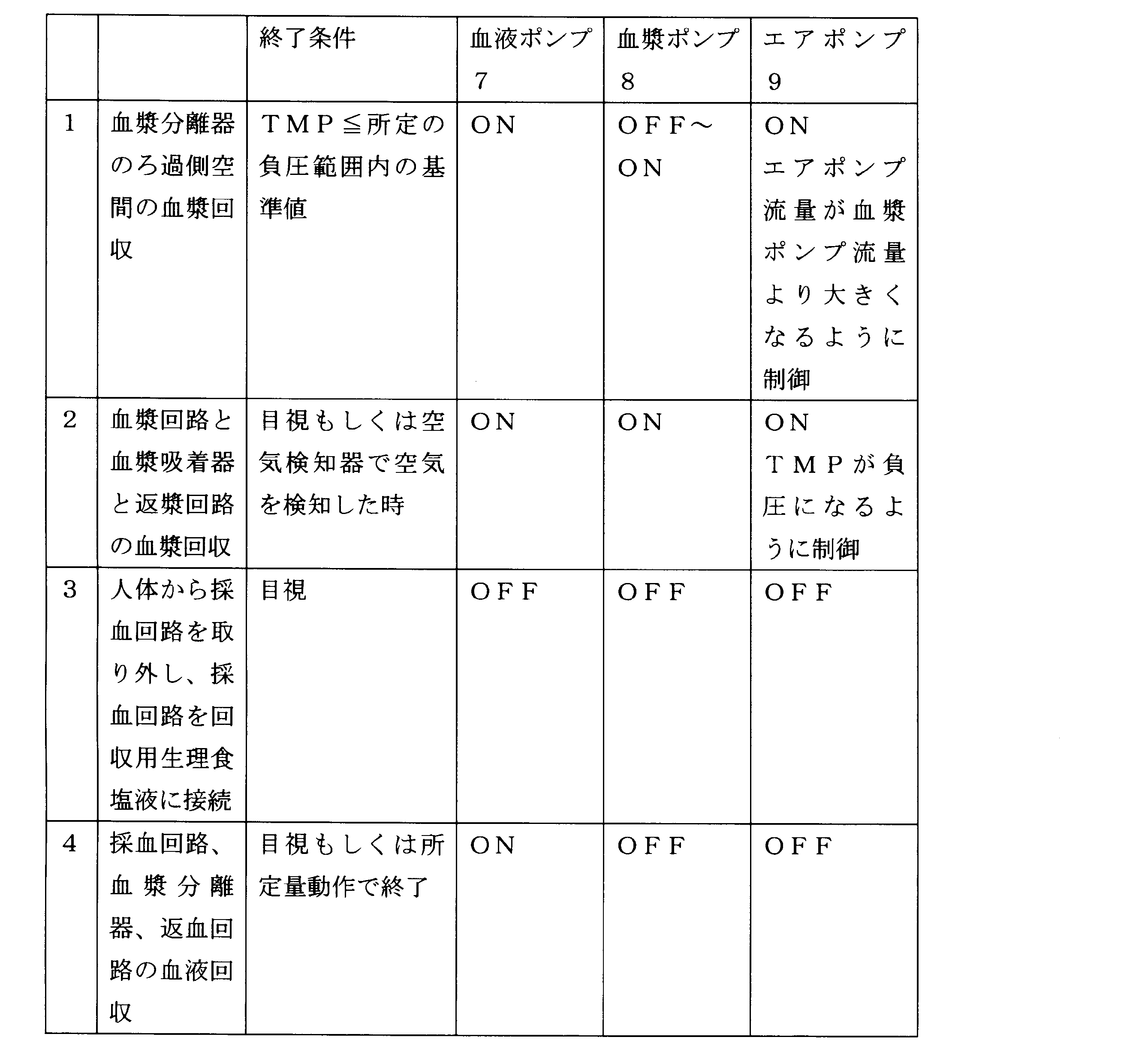
- Table 1 summarizes an example of blood and plasma recovery operations and operating states of the blood pump 7, plasma pump 8, air pump 9, and reversion pump 16.
- FIG. 2 shows a configuration example of a plasma adsorption device (plasma purification device) 51 according to an embodiment of the present invention.
- the plasma adsorption device 51 has a plasma separator 5 and a plasma adsorber 6b.
- a blood collection circuit 1 is connected to the blood inlet of the plasma separator 5, and a blood pump 7 is disposed in the blood collection circuit 1. Between the blood pump 7 and the plasma separator 5, the first pressure measuring means 10 is disposed.
- a blood return circuit 2 is connected to the blood outlet of the plasma separator 5, and the second pressure measuring means 11 is disposed in the blood return circuit 2.
- the first pressure measurement circuit 3 is connected to the first filtration outlet of the plasma separator 5, the plasma circuit 4 is connected to the second filtration outlet, and the plasma circuit 4 is connected to the plasma adsorber 6b.
- a plasma pump 8 is disposed in the plasma circuit 4.
- the plasma adsorption device 51 further includes a calculation unit 30 and a control unit 31.
- the calculation means 30 and the control means 31 are connected.
- the calculation means 30 is connected to the first pressure measurement means 10, the second pressure measurement means 11, and the third pressure measurement means 12, and the control means 31 is blood.
- a pump 7, a plasma pump 8, and an air pump 9 are connected.
- the above is the overall configuration of the plasma adsorption device 51 of the present invention. Next, an operation method of the plasma adsorption device 51 that collects blood and plasma after the plasma purification is completed will be described.
- the blood side space of the blood collection circuit 1, the blood return circuit 2, and the plasma separator 5 is filled with blood. Further, the filtration side space of the plasma separator 5, the plasma circuit 4, the plasma adsorber 6b, and the return circuit 15 are filled with plasma. At this time, blood collection circuit 1 and blood return circuit 2 remain connected to the patient, and blood pump 7 and plasma pump 8 remain in operation.
- plasma is first collected.
- the plasma in the filtration side space of the plasma separator 5 is sent to the blood side space of the plasma separator 5 or the plasma circuit 4 and collected.
- the plasma delivered to the blood side space is directly collected in the blood return circuit 2, and the plasma delivered to the plasma circuit 4 passes through the plasma circuit 4, the plasma adsorber 6 b and the plasma return circuit 15 in principle. 2 recovered.
- the blood pump 7 remains operating, and the blood in the blood collection circuit 1, the blood side space of the plasma separator 5, and the blood in the blood return circuit 2 circulate.
- the air pump 9 is operated while the plasma pump 8 is operated, and the flow rates of the air pump 9 and the plasma pump 8 are controlled so that the pressure in the filtration side space of the plasma separator 5 becomes higher than the pressure in the blood side space. Specifically, the flow rate is adjusted so that the flow rate of the air pump 9 is larger than the flow rate of the plasma pump 8. As long as the flow rate of the air pump 9 is larger than the flow rate of the plasma pump 8, only the air pump 9 may be operated to stop the plasma pump 8. Since air is sent to the filtration side space by the air pump 9 and the pressure of the filtration side space of the plasma separator 5 is higher than the pressure of the blood side space, the plasma is newly separated from the blood by the plasma separator 5. Absent. Then, the amount of air in the filtration side space of the plasma separator 5 gradually increases, and eventually the filtration side space of the plasma separator 5 is replaced with air.
- the filter membrane such as a hollow fiber once wetted has a property that air does not pass through. Compressed in the filtration side space of the separator 5 increases the pressure P3, and the transmembrane pressure difference TMP becomes negative. When the transmembrane pressure difference TMP becomes equal to or less than the reference value in the predetermined negative pressure range, the plasma recovery in the filtration side space of the plasma separator 5 is finished. At this time, all the plasma in the filtration side space of the plasma separator 5 is collected in the blood side space of the plasma separator 5 or in the plasma circuit 4.
- the plasma in the plasma circuit 4 is collected.
- the plasma pump 7 continues to operate and blood circulates.
- the flow rate of the air pump 9 and the plasma pump 8 is controlled so that the transmembrane pressure difference TMP falls within a predetermined negative pressure range, and the plasma in the plasma circuit 4 is sent to the plasma adsorber 6b.
- the difference between the pressure in the blood side space and the pressure in the filtration side space higher than that can be adjusted to a preset reference value (here, the absolute value of the lower limit value in a predetermined negative pressure range) or less.
- the value of the differential pressure TMP is too low (the differential pressure is too large), and an excessive burden is placed on the separation membrane of the plasma separator 5 trying to flow a large amount of plasma in the filtration side space into the blood side space. Can be prevented.
- the transmembrane pressure difference TMP is too high (the pressure difference is too small), and new plasma can be prevented from flowing from the blood side space of the plasma separator 5 into the filtration side space.
- the predetermined negative pressure range is ⁇ 100 mmHg ( ⁇ 13.3 kPa) in consideration of the measurement accuracy of the pressure measuring means and the appropriate internal pressure of the circuit.
- the predetermined negative pressure range is not less than ⁇ 80 mmHg ( ⁇ 10.6 kPa) and not more than ⁇ 20 mmHg ( ⁇ 2.6 kPa).
- the flow rate of the air pump is adjusted so as to be larger than the flow rate of the plasma pump, and the transmembrane pressure difference TMP is set within the predetermined negative pressure range. If the lower limit is not reached, the air pump is stopped and the plasma pump is activated. Moreover, if the transmembrane pressure difference TMP is within a predetermined negative pressure range, either the flow rate of the air pump 9 or the flow rate of the plasma pump 8 may be variable, but the flow rate returning to the patient is preferably constant. It is preferable to make the flow rate of the plasma pump 8 constant and make the flow rate of the air pump 9 variable.
- ON / OFF control of the air pump 9 is advantageous in terms of cost, ON / OFF control is preferable.
- the plasma circuit 4, the plasma adsorber 6b, and the return circuit 15 are replaced with air, the collection of the plasma is terminated. The end of this step may be carried out while visually confirming by the operator, or may be automatically terminated when an air detector is provided in the return circuit 15 and air is detected.
- the stop time of the blood pump 7 is 1 minute or less, and there is no fear of blood coagulation.
- the operation of the blood pump 7 is resumed, and the blood of the blood collection circuit 1, the plasma separator 5 and the blood return circuit 2 is collected.
- the plasma pump 8 is stopped, but since the collection of the plasma has already been completed, there is no possibility that the plasma coagulates.
- Table 2 summarizes examples of blood and plasma recovery operations and operating states of the blood pump 7, plasma pump 8, and air pump 9.
- the plasma purification apparatus of the present invention can be used for plasma purification therapy such as plasma component separation or plasma adsorption.
Landscapes
- Health & Medical Sciences (AREA)
- Heart & Thoracic Surgery (AREA)
- Vascular Medicine (AREA)
- Life Sciences & Earth Sciences (AREA)
- Biomedical Technology (AREA)
- Engineering & Computer Science (AREA)
- General Health & Medical Sciences (AREA)
- Hematology (AREA)
- Animal Behavior & Ethology (AREA)
- Anesthesiology (AREA)
- Public Health (AREA)
- Veterinary Medicine (AREA)
- Cardiology (AREA)
- Biodiversity & Conservation Biology (AREA)
- Cell Biology (AREA)
- Molecular Biology (AREA)
- External Artificial Organs (AREA)
- Medicines Containing Material From Animals Or Micro-Organisms (AREA)
Abstract
Description
(ii) 前記制御手段は、前記血漿分離器の濾過側空間内の血漿が空気に置換された後、前記血液ポンプを引き続き作動させつつ、前記血液側空間の圧力とそれより高い前記濾過側空間の圧力との差が、予め設定された基準値以下になるように前記血漿ポンプと前記エアポンプの流量を制御して、前記血漿回路内の血漿を前記血漿成分分離器または血漿吸着器に送出させる、(i)に記載の血漿浄化装置。
(iii) 前記血漿浄化装置は、前記採血回路の圧力P1を測定する第一の圧力測定手段と、前記返血回路の圧力P2を測定する第二の圧力測定手段と、前記第一の圧力測定回路の圧力P3を測定する第三の圧力測定手段と、前記圧力P1、P2、P3から式(1)または式(2)のいずれか1つの式で定義される膜間差圧TMPを計算する演算手段と、をさらに有し、前記制御手段は、前記膜間差圧TMPが所定の負圧範囲になるように、前記血漿ポンプと前記エアポンプの流量を制御して、前記血漿回路内の血漿を前記血漿成分分離器または血漿吸着器に送出させる、(ii)に記載の血漿浄化装置。
(P1+P2)/2-P3=TMP ・・・ (1)
P1-P3 = TMP ・・・ (2)
(iv) 前記制御手段は、前期膜間差圧TMPが所定の負圧範囲の上限値以上になった場合には、エアポンプの流量が血漿ポンプの流量より大きくなるように調節し、膜間差圧TMPが所定の負圧範囲の下限値以下になった場合には、エアポンプを停止して血漿ポンプを作動させる、(iii)に記載の血漿浄化装置。
(v) 前記TMPの所定の負圧範囲が-100mmHg以上-10mmHg以下である、(iii)又は(iv)に記載の血漿浄化装置。
(vi) 前記血漿浄化装置は血漿成分分離器を有するものであって、前記血漿ポンプと血漿成分分離器との間の血漿回路の圧力P4を測定する第四の圧力測定手段と、前記血漿成分分離器の濾過側空間の第一の血漿成分出口に接続された分岐回路と、前記分岐回路に設置された返漿ポンプと、を有し、前記返漿回路は、前記血漿成分分離器の濾過側空間の第二の血漿成分出口と前記返血回路とを接続し、前記演算手段は、前記圧力P3とP4から式(3)で定義される差圧ΔPを計算し、前記制御手段は、該差圧ΔPが所定の圧力範囲にある基準値以上になった時に、前記血液ポンプを引き続き作動させつつ、前記血漿ポンプと前記エアポンプを停止させ、前記返漿ポンプを作動させて、前記血漿成分分離器の濾過側空間と前記返漿回路の血漿を前記返血回路に送出する、(i)~(v)のいずれかに記載の血漿浄化装置。
P4-P3=ΔP ・・・ (3)
(vii) 前記ΔPの所定の圧力範囲が200mmHg以上500mmHg以下である、(vi)に記載の血漿浄化装置。
(viii) 前記制御手段は、前記エアポンプを作動させ、前記血漿ポンプを停止させて、前記血漿分離器の濾過側空間の血漿を、前記血漿分離器の血液側空間に送出する、(i)~(vii)のいずれかに記載の血漿浄化装置。
(iX) 血液入口に採血回路、血液出口に返血回路、第一の濾過出口に第一の圧力測定回路、第二の濾過出口に血漿回路がそれぞれ接続された血漿分離器と、血漿入口に前記血漿回路、血漿出口に、前記返血回路に通じる返漿回路がそれぞれ接続された血漿成分分離器または血漿吸着器と、前記採血回路に設置されて血液を血漿分離器の血液側空間に供給する血液ポンプと、前記血漿回路に設置されて血漿を血漿成分分離器または血漿吸着器に供給する血漿ポンプと、前記第一の圧力測定回路に設置されて空気を血漿分離器の濾過側空間に供給するエアポンプと、前記血液ポンプ、前記血漿ポンプおよび前記エアポンプの流量を制御する制御手段と、を備える、血漿浄化装置であって、前記制御手段は、前記血液ポンプを作動させ、血液を前記血漿分離器の血液側空間に送出させつつ、前記エアポンプと前記血漿ポンプの流量を制御して、前記血漿分離器の濾過側空間に空気を供給することにより、前記濾過側空間に残存する血漿を、前記血液側空間および前記血漿回路に送出させ、前記エアポンプと前記血漿ポンプの流量を制御して、前記血漿回路内に残存する血漿を、前記血漿成分分離器または前記血漿吸着器に送出させる、血液浄化装置。
(x) 血液ポンプを作動させ、血液を血漿分離器の血液側空間に送出させつつ、前記血漿分離器の濾過側空間に空気を供給することにより、前記濾過側空間に残存する血漿を、前記血液側空間および血漿回路に送出させる工程と、前記血漿回路内に空気を供給することにより、前記血漿回路内に残存する血漿を、血漿成分分離器または血漿吸着器に送出させる工程と、を含む、血漿浄化装置の制御方法。
(P1+P2)/2-P3=TMP ・・・ (1)
P1-P3 = TMP ・・・・ (2)

2 返血回路
3 第一の圧力測定回路
4 血漿回路
5 血漿分離器
6a 血漿成分分離器
6b 血漿吸着器
7 血液ポンプ
8 血漿ポンプ
9 エアポンプ
10 第一の圧力測定手段
11 第二の圧力測定手段
12 第三の圧力測定手段
13 第四の圧力測定手段
14 分岐回路
15 返漿回路
16 返漿ポンプ
20 第一のバルブ
21 第二のバルブ
30 演算手段
31 制御手段
50 血漿成分分離装置(血漿浄化装置)
51 血漿吸着装置(血漿浄化装置)
Claims (10)
- 血液入口に採血回路、血液出口に返血回路、第一の濾過出口に第一の圧力測定回路、第二の濾過出口に血漿回路がそれぞれ接続された血漿分離器と、血漿入口に前記血漿回路、血漿出口に、前記返血回路に通じる返漿回路がそれぞれ接続された血漿成分分離器または血漿吸着器とを有する血漿浄化装置であって、
前記採血回路に設置されて血液を血漿分離器の血液側空間に供給する血液ポンプと、
前記血漿回路に設置されて血漿を血漿成分分離器または血漿吸着器に供給する血漿ポンプと、
前記第一の圧力測定回路に設置されて空気を血漿分離器の濾過側空間に供給するエアポンプと、
血漿浄化終了時に前記血液ポンプを停止することなく引き続き作動させて、血液を前記血漿分離器の血液側空間に送出させつつ、前記血漿分離器の濾過側空間の圧力が血液側空間の圧力より高くなるように前記エアポンプと前記血漿ポンプの流量を制御して、前記血漿分離器の濾過側空間に残されている血漿を、前記エアポンプからの空気の供給により前記血漿分離器の血液側空間または血漿回路に送出させる制御手段と、を有する、血漿浄化装置。 - 前記制御手段は、前記血漿分離器の濾過側空間内の血漿が空気に置換された後、前記血液ポンプを引き続き作動させつつ、前記血液側空間の圧力とそれより高い前記濾過側空間の圧力との差が、予め設定された基準値以下になるように前記血漿ポンプと前記エアポンプの流量を制御して、前記血漿回路内の血漿を前記血漿成分分離器または血漿吸着器に送出させる、請求項1に記載の血漿浄化装置。
- 前記採血回路の圧力P1を測定する第一の圧力測定手段と、
前記返血回路の圧力P2を測定する第二の圧力測定手段と、
前記第一の圧力測定回路の圧力P3を測定する第三の圧力測定手段と、
前記圧力P1、P2、P3から式(1)または式(2)のいずれか1つの式で定義される膜間差圧TMPを計算する演算手段と、をさらに有し、
前記制御手段は、前記膜間差圧TMPが所定の負圧範囲になるように、前記血漿ポンプと前記エアポンプの流量を制御して、前記血漿回路内の血漿を前記血漿成分分離器または血漿吸着器に送出させる、請求項2に記載の血漿浄化装置。
(P1+P2)/2-P3=TMP ・・・ (1)
P1-P3 = TMP ・・・ (2) - 前記制御手段は、前記膜間差圧TMPが所定の負圧範囲の上限値以上になった場合には、エアポンプの流量が血漿ポンプの流量より大きくなるように調節し、膜間差圧TMPが所定の負圧範囲の下限値以下になった場合には、エアポンプを停止して血漿ポンプを作動させる、請求項3に記載の血漿浄化装置。
- 前記TMPの所定の負圧範囲が-100mmHg以上-10mmHg以下である、請求項3又は4に記載の血漿浄化装置。
- 前記血漿浄化装置は血漿成分分離器を有するものであって、
前記血漿ポンプと血漿成分分離器との間の血漿回路の圧力P4を測定する第四の圧力測定手段と、
前記血漿成分分離器の濾過側空間の第一の血漿成分出口に接続された分岐回路と、
前記分岐回路に設置された返漿ポンプと、を有し、
前記返漿回路は、前記血漿成分分離器の濾過側空間の第二の血漿成分出口と前記返血回路とを接続し、
前記演算手段は、前記圧力P3とP4から式(3)で定義される差圧ΔPを計算し、
前記制御手段は、該差圧ΔPが所定の圧力範囲にある基準値以上になった時に、前記血液ポンプを引き続き作動させつつ、前記血漿ポンプと前記エアポンプを停止させ、前記返漿ポンプを作動させて、前記血漿成分分離器の濾過側空間と前記返漿回路の血漿を前記返血回路に送出する、請求項1~5のいずれかに記載の血漿浄化装置。
P4-P3=ΔP ・・・ (3) - 前記ΔPの所定の圧力範囲が200mmHg以上500mmHg以下である、請求項6に記載の血漿浄化装置。
- 前記制御手段は、前記エアポンプを作動させ、前記血漿ポンプを停止させて、前記血漿分離器の濾過側空間の血漿を、前記血漿分離器の血液側空間に送出する、請求項1~7のいずれかに記載の血漿浄化装置。
- 血液入口に採血回路、血液出口に返血回路、第一の濾過出口に第一の圧力測定回路、第二の濾過出口に血漿回路がそれぞれ接続された血漿分離器と、
血漿入口に前記血漿回路、血漿出口に、前記返血回路に通じる返漿回路がそれぞれ接続された血漿成分分離器または血漿吸着器と、
前記採血回路に設置されて血液を血漿分離器の血液側空間に供給する血液ポンプと、
前記血漿回路に設置されて血漿を血漿成分分離器または血漿吸着器に供給する血漿ポンプと、
前記第一の圧力測定回路に設置されて空気を血漿分離器の濾過側空間に供給するエアポンプと、
前記血液ポンプ、前記血漿ポンプおよび前記エアポンプの流量を制御する制御手段と、
を備える、血漿浄化装置であって、
前記制御手段は、前記血液ポンプを作動させ、血液を前記血漿分離器の血液側空間に送出させつつ、前記エアポンプと前記血漿ポンプの流量を制御して、前記血漿分離器の濾過側空間に空気を供給することにより、前記濾過側空間に残存する血漿を、前記血液側空間および前記血漿回路に送出させ、前記エアポンプと前記血漿ポンプの流量を制御して、前記血漿回路内に残存する血漿を、前記血漿成分分離器または前記血漿吸着器に送出させる、血液浄化装置。 - 血液ポンプを作動させ、血液を血漿分離器の血液側空間に送出させつつ、前記血漿分離器の濾過側空間に空気を供給することにより、前記濾過側空間に残存する血漿を、前記血液側空間および血漿回路に送出させる工程と、
前記血漿回路内に空気を供給することにより、前記血漿回路内に残存する血漿を、血漿成分分離器または血漿吸着器に送出させる工程と、
を含む、血漿浄化装置の制御方法。
Priority Applications (4)
| Application Number | Priority Date | Filing Date | Title |
|---|---|---|---|
| EP09827364.2A EP2351588B1 (en) | 2008-11-19 | 2009-11-19 | Plasma purifying device |
| JP2010539149A JP5385917B2 (ja) | 2008-11-19 | 2009-11-19 | 血漿浄化装置及び血液浄化装置の制御方法 |
| CN200980146281.9A CN102215886B (zh) | 2008-11-19 | 2009-11-19 | 血浆净化装置 |
| US13/129,703 US8758603B2 (en) | 2008-11-19 | 2009-11-19 | Plasma purifying device and method of controlling plasma purifying device |
Applications Claiming Priority (2)
| Application Number | Priority Date | Filing Date | Title |
|---|---|---|---|
| JP2008-295719 | 2008-11-19 | ||
| JP2008295719 | 2008-11-19 |
Publications (1)
| Publication Number | Publication Date |
|---|---|
| WO2010058583A1 true WO2010058583A1 (ja) | 2010-05-27 |
Family
ID=42198026
Family Applications (1)
| Application Number | Title | Priority Date | Filing Date |
|---|---|---|---|
| PCT/JP2009/006235 Ceased WO2010058583A1 (ja) | 2008-11-19 | 2009-11-19 | 血漿浄化装置及び血液浄化装置の制御方法 |
Country Status (5)
| Country | Link |
|---|---|
| US (1) | US8758603B2 (ja) |
| EP (1) | EP2351588B1 (ja) |
| JP (1) | JP5385917B2 (ja) |
| CN (1) | CN102215886B (ja) |
| WO (1) | WO2010058583A1 (ja) |
Cited By (3)
| Publication number | Priority date | Publication date | Assignee | Title |
|---|---|---|---|---|
| CN103520786A (zh) * | 2013-10-16 | 2014-01-22 | 上海工程技术大学 | 一种血液净化蠕动泵流量的控制方法 |
| WO2020202657A1 (ja) | 2019-04-01 | 2020-10-08 | 日機装株式会社 | 血液浄化装置 |
| US20210030943A1 (en) * | 2018-02-01 | 2021-02-04 | Southern Medical University Zhujiang Hospital | Combined Bio-Artificial Liver Support System |
Families Citing this family (6)
| Publication number | Priority date | Publication date | Assignee | Title |
|---|---|---|---|---|
| CN102716519A (zh) * | 2012-07-03 | 2012-10-10 | 中国人民武装警察部队后勤学院附属医院 | 基于Diapact CRRT实现连续性血液净化的装置 |
| DE102014109136A1 (de) * | 2014-06-30 | 2015-12-31 | Fresenius Medical Care Deutschland Gmbh | Verfahren zum Entfernen von Fluid aus einem Blutfilter nach Beendigung einer Blutbehandlungssitzung mittels Flusserhöhung und Behandlungsvorrichtung zum Durchführen desselben |
| CN107583120B (zh) * | 2017-09-20 | 2024-05-14 | 中南大学湘雅二医院 | 一种血浆置换透析吸附系统 |
| CN112055601B (zh) | 2017-12-28 | 2024-08-20 | 艾赛普公司 | 用于处理出血流体以便自体输注的系统和方法 |
| FR3097770B1 (fr) | 2019-06-27 | 2024-03-01 | I Sep | Système et procédé de traitement de liquide hémorragique pour de l’autotransfusion |
| CN115350350B (zh) * | 2022-08-18 | 2026-04-03 | 健帆生物科技集团股份有限公司 | 血液净化设备的回血控制方法、血液净化设备及计算机可读存储介质 |
Citations (10)
| Publication number | Priority date | Publication date | Assignee | Title |
|---|---|---|---|---|
| JPS61113457A (ja) * | 1984-11-06 | 1986-05-31 | 鐘淵化学工業株式会社 | 血液成分処理回路の初期設定方法及び初期設定機構 |
| JPS62281956A (ja) * | 1986-05-29 | 1987-12-07 | 横河電機株式会社 | 血中成分除去装置 |
| JPS645563A (en) * | 1987-06-30 | 1989-01-10 | Terumo Corp | Apparatus for removing unnecessary substance in blood |
| JPH0117704B2 (ja) | 1985-12-17 | 1989-03-31 | Kurare Kk | |
| JPH02177962A (ja) * | 1988-12-28 | 1990-07-11 | Toshikatsu Gounai | 生体血流中の固形病因物質を体外除去する体外循環装置と、同固形病因物質を体外除去する方法、および生体血液浄化療法 |
| WO1992017220A1 (en) * | 1991-03-26 | 1992-10-15 | Otsuka Pharmaceutical Factory, Inc. | Method and device for filtering plasma |
| JPH0538362A (ja) * | 1991-08-06 | 1993-02-19 | Terumo Corp | 血漿処理装置 |
| JPH0788179A (ja) * | 1993-09-22 | 1995-04-04 | Terumo Corp | 血漿交換装置 |
| JPH1080478A (ja) * | 1996-09-09 | 1998-03-31 | Kanegafuchi Chem Ind Co Ltd | 二重濾過による血漿処理方法及び血漿処理装置 |
| JP2001054571A (ja) | 1999-08-18 | 2001-02-27 | Yokogawa Electric Corp | 血漿浄化装置 |
Family Cites Families (4)
| Publication number | Priority date | Publication date | Assignee | Title |
|---|---|---|---|---|
| JPH0629083B2 (ja) | 1987-07-10 | 1994-04-20 | 株式会社ダイフク | 物品収集設備 |
| US6083187A (en) | 1996-09-09 | 2000-07-04 | Kaneka Corporation | Method and apparatus for treating blood |
| CN2689953Y (zh) * | 2003-12-15 | 2005-04-06 | 王晓宁 | 血浆净化装置 |
| CN100493633C (zh) * | 2007-04-27 | 2009-06-03 | 高光勇 | 人工肝肾支持系统 |
-
2009
- 2009-11-19 CN CN200980146281.9A patent/CN102215886B/zh active Active
- 2009-11-19 JP JP2010539149A patent/JP5385917B2/ja active Active
- 2009-11-19 US US13/129,703 patent/US8758603B2/en not_active Expired - Fee Related
- 2009-11-19 EP EP09827364.2A patent/EP2351588B1/en active Active
- 2009-11-19 WO PCT/JP2009/006235 patent/WO2010058583A1/ja not_active Ceased
Patent Citations (10)
| Publication number | Priority date | Publication date | Assignee | Title |
|---|---|---|---|---|
| JPS61113457A (ja) * | 1984-11-06 | 1986-05-31 | 鐘淵化学工業株式会社 | 血液成分処理回路の初期設定方法及び初期設定機構 |
| JPH0117704B2 (ja) | 1985-12-17 | 1989-03-31 | Kurare Kk | |
| JPS62281956A (ja) * | 1986-05-29 | 1987-12-07 | 横河電機株式会社 | 血中成分除去装置 |
| JPS645563A (en) * | 1987-06-30 | 1989-01-10 | Terumo Corp | Apparatus for removing unnecessary substance in blood |
| JPH02177962A (ja) * | 1988-12-28 | 1990-07-11 | Toshikatsu Gounai | 生体血流中の固形病因物質を体外除去する体外循環装置と、同固形病因物質を体外除去する方法、および生体血液浄化療法 |
| WO1992017220A1 (en) * | 1991-03-26 | 1992-10-15 | Otsuka Pharmaceutical Factory, Inc. | Method and device for filtering plasma |
| JPH0538362A (ja) * | 1991-08-06 | 1993-02-19 | Terumo Corp | 血漿処理装置 |
| JPH0788179A (ja) * | 1993-09-22 | 1995-04-04 | Terumo Corp | 血漿交換装置 |
| JPH1080478A (ja) * | 1996-09-09 | 1998-03-31 | Kanegafuchi Chem Ind Co Ltd | 二重濾過による血漿処理方法及び血漿処理装置 |
| JP2001054571A (ja) | 1999-08-18 | 2001-02-27 | Yokogawa Electric Corp | 血漿浄化装置 |
Cited By (7)
| Publication number | Priority date | Publication date | Assignee | Title |
|---|---|---|---|---|
| CN103520786A (zh) * | 2013-10-16 | 2014-01-22 | 上海工程技术大学 | 一种血液净化蠕动泵流量的控制方法 |
| US20210030943A1 (en) * | 2018-02-01 | 2021-02-04 | Southern Medical University Zhujiang Hospital | Combined Bio-Artificial Liver Support System |
| US11911552B2 (en) * | 2018-02-01 | 2024-02-27 | Southern Medical University Zhujiang Hospital | Combined bio-artificial liver support system |
| US12311097B2 (en) | 2018-02-01 | 2025-05-27 | Southern Medical University Zhujiang Hospital | Combined bio-artificial liver support system |
| WO2020202657A1 (ja) | 2019-04-01 | 2020-10-08 | 日機装株式会社 | 血液浄化装置 |
| JP2020168039A (ja) * | 2019-04-01 | 2020-10-15 | 日機装株式会社 | 血液浄化装置 |
| US12042591B2 (en) | 2019-04-01 | 2024-07-23 | Nikkiso Company Limited | Blood purification device |
Also Published As
| Publication number | Publication date |
|---|---|
| US20110284467A1 (en) | 2011-11-24 |
| JPWO2010058583A1 (ja) | 2012-04-19 |
| US8758603B2 (en) | 2014-06-24 |
| EP2351588B1 (en) | 2016-01-27 |
| EP2351588A4 (en) | 2013-01-23 |
| EP2351588A1 (en) | 2011-08-03 |
| JP5385917B2 (ja) | 2014-01-08 |
| CN102215886B (zh) | 2014-09-17 |
| CN102215886A (zh) | 2011-10-12 |
Similar Documents
| Publication | Publication Date | Title |
|---|---|---|
| JP5385917B2 (ja) | 血漿浄化装置及び血液浄化装置の制御方法 | |
| JP6685374B2 (ja) | 血液浄化装置及びそのプライミング方法 | |
| EP2550984B1 (en) | Blood purification device | |
| KR101240773B1 (ko) | 혈액투석 또는 혈액(투석)여과용 장치 및 혈액투석 또는 혈액(투석)여과용 장치의 제어 방법 | |
| CN1604798B (zh) | 自动血液透析装置及使用该装置的起动方法 | |
| JP6995916B2 (ja) | 体液から物質を濾過する為の接線流フィルターシステム | |
| US20130292313A1 (en) | Apparatus for extracorporeal blood treatment | |
| JP2021509351A (ja) | 自己輸血のための出血液を処理するためのシステムおよび方法 | |
| JP2012192099A (ja) | 血液浄化装置 | |
| EP1524000A2 (en) | Blood treatment machine and unit | |
| CN109069723B (zh) | 血液净化系统和其启动加注方法 | |
| CN110691617B (zh) | 血液净化装置 | |
| JP6566687B2 (ja) | 血液浄化装置、血液浄化装置のプライミング方法及び作動方法 | |
| JP2017217161A (ja) | 血液浄化装置及びそのプライミング方法 | |
| JP7527174B2 (ja) | 体腔液処理システム | |
| CN110709115B (zh) | 血液净化装置 | |
| JP2003265600A (ja) | 残留液の排出方法及び排出装置 | |
| JP2023075575A (ja) | 体腔液処理システム | |
| JP5345373B2 (ja) | 血液体外循環装置及び血液体外循環装置の作動方法 | |
| JP2000197698A (ja) | 血液浄化装置 |
Legal Events
| Date | Code | Title | Description |
|---|---|---|---|
| WWE | Wipo information: entry into national phase |
Ref document number: 200980146281.9 Country of ref document: CN |
|
| 121 | Ep: the epo has been informed by wipo that ep was designated in this application |
Ref document number: 09827364 Country of ref document: EP Kind code of ref document: A1 |
|
| ENP | Entry into the national phase |
Ref document number: 2010539149 Country of ref document: JP Kind code of ref document: A |
|
| WWE | Wipo information: entry into national phase |
Ref document number: 2009827364 Country of ref document: EP |
|
| NENP | Non-entry into the national phase |
Ref country code: DE |
|
| WWE | Wipo information: entry into national phase |
Ref document number: 13129703 Country of ref document: US |