WO2010058463A1 - 偏向器調整方法、および偏向ユニット - Google Patents
偏向器調整方法、および偏向ユニット Download PDFInfo
- Publication number
- WO2010058463A1 WO2010058463A1 PCT/JP2008/071089 JP2008071089W WO2010058463A1 WO 2010058463 A1 WO2010058463 A1 WO 2010058463A1 JP 2008071089 W JP2008071089 W JP 2008071089W WO 2010058463 A1 WO2010058463 A1 WO 2010058463A1
- Authority
- WO
- WIPO (PCT)
- Prior art keywords
- deflector
- back surface
- deflection
- base
- adjustment
- Prior art date
- Legal status (The legal status is an assumption and is not a legal conclusion. Google has not performed a legal analysis and makes no representation as to the accuracy of the status listed.)
- Ceased
Links
Images




Classifications
-
- G—PHYSICS
- G02—OPTICS
- G02B—OPTICAL ELEMENTS, SYSTEMS OR APPARATUS
- G02B26/00—Optical devices or arrangements for the control of light using movable or deformable optical elements
- G02B26/08—Optical devices or arrangements for the control of light using movable or deformable optical elements for controlling the direction of light
- G02B26/10—Scanning systems
- G02B26/105—Scanning systems with one or more pivoting mirrors or galvano-mirrors
Definitions
- the present invention relates to a deflector adjustment method for adjusting a deflector mounted on an optical apparatus that scans a laser beam on a surface to be scanned, and a deflection unit having a deflector suitable for performing the adjustment by the method.
- a deflection for deflecting laser light emitted from a light source in order to draw a scanning line on a surface to be scanned is installed.
- the deflector is attached to the case of the optical device through a precise adjustment process so that the laser beam is scanned on the surface to be scanned with high accuracy.
- FIG. 1 is a perspective view showing a configuration of a deflection unit 10 equipped with a deflector 1 (for example, a galvano mirror) that is a component to be adjusted.
- a deflector 1 for example, a galvano mirror
- FIG. 1 or subsequent figures the alternate long and short dash line is the central axis (optical axis) AX of the optical apparatus on which the deflection unit is mounted.
- a direction parallel to the central axis AX is defined as “Y direction”, and two directions orthogonal to the Y direction and orthogonal to each other are defined as “X direction” and “Z direction”.
- an adjustment telescope (not shown) is used for adjustment of the deflector 1.
- the deflection unit 10 includes a fine adjustment precision stage 2 that finely adjusts the position or angle of the deflector 1 in four axis directions.
- the fine adjustment precision stage 2 holds the deflector 1 so as to be movable in the X, Y, and Z directions and to be rotatable on the XY plane. In the adjustment process, the operator operates the fine adjustment precision stage 2 to adjust the position and angle of the deflector 1.
- the specific work of the operator in the adjustment process is as follows.
- the operator attaches a cover cap 3 that covers the entire deflector 1 to the deflector 1.
- a cross-shaped index 3 i is attached to the outer surface of the cover cap 3.
- the operator operates the fine adjustment precision stage 2 while looking through the eyepiece of the adjustment telescope so as to align the center of the deflection surface 1r of the deflector 1 with the center axis AX. Move in the Z direction).
- the operator finely adjusts the position of the deflector 1 so that the center of the index 3i (the intersection of each line forming a cross) matches the center of the reticle of the telescope.
- the operator removes the cover cap 3 from the deflector 1.
- the light source of the adjustment telescope is turned on to irradiate the measurement light onto the deflection surface 1 r of the deflector 1.
- the operator looks into the eyepiece of the adjustment telescope again and observes the reflected light of the measurement light irradiated on the deflection surface 1r.
- the operator finely adjusts the deflection surface 1r to an appropriate angle, specifically, to adjust the deflection surface 1r to an angle perpendicular to the central axis AX (in other words, to be parallel to the XZ plane).
- the deflector 1 is rotated on the XY plane by operating the precision stage 2 for adjustment.
- the operator finely adjusts the angle of the deflection surface 1r so that the reflected light returns to the center of the reticle. Through the adjustment process described above, the deflector 1 is adjusted to an appropriate position and angle.
- the present invention has been made in view of the above circumstances, and an object of the present invention is to adjust a deflector suitable for accurately adjusting a deflector while effectively avoiding damage to a deflecting surface and adhesion of dirt. It is to provide a method and a deflection unit with a deflector suitable for performing the adjustment.
- a deflector adjustment method that solves the above problem is a method for adjusting a deflector mounted on an optical device that scans a laser beam on a surface to be scanned, and has the following characteristics. . That is, in this deflector adjustment method, a base placement step for placing the base holding the deflector at a predetermined reference position so that the position or angle of the deflector can be adjusted, and the base are placed at the reference position.
- the first deflector rotating step for rotating the deflector so that the back surface of the deflecting surface for deflecting the laser beam of the deflector is substantially directly opposed to the predetermined measuring machine, and the specific position of the index on the back surface is measured.
- a deflector position adjusting step for adjusting the position of the deflector by the base so as to be aligned with the reference axis of the machine, and a second deflector rotating step for rotating the deflector so that the deflecting surface substantially faces the measuring machine
- a deflector angle adjustment step for adjusting the angle of the deflector by the base so that the reflected light on the deflection surface of the measurement light irradiated by the measuring instrument returns to the reference axis of the measuring instrument.
- the deflector adjusting method when adjusting the position of the deflector using the index, it is only necessary to rotate the deflector so that the back surface of the deflector faces the measuring instrument. Unlike the adjustment work conventionally performed by touching the deflector directly, it is not necessary to attach or remove the cover cap with the indicator from the deflector. For this reason, during the adjustment work of the deflector, the occurrence of the problem of damaging the deflecting surface or attaching dirt to the deflecting surface is suitably suppressed. Further, since the cover cap with the index itself is not used, the adjustment accuracy of the deflector cannot be lowered due to the individual difference of the cover cap or the mounting error. According to another aspect, since the deflector itself has an index, a relative deviation between the index and the deflector cannot occur.
- the index may be, for example, a groove or a protrusion formed on the back surface so as to form a predetermined pattern when facing from the back surface of the deflector, or a predetermined mark printed on the back surface. May be.
- the indicator may be a pattern applied to the surface of the cover that covers the back surface or a formed pattern when a cover that exposes the deflection surface is attached to the deflector.
- the deflector In the first deflector rotating step or the second deflector rotating step, whether the deflector is electrically rotated by driving an actuator mounted on the base, or whether the deflector is manually rotated. Alternatively, by rotating the deflector by using both electrical rotation by the actuator and manual rotation, the deflecting surface is substantially aligned with the measuring instrument when the second deflector rotating step is executed. When this is done, it is preferable that the actuator is stopped at substantially the center of the rotatable range of the actuator.
- a deflection unit that solves the above-described problems is a unit that is mounted on an optical instrument that scans a laser beam on a surface to be scanned, and has the following characteristics. That is, such a deflection unit has a deflector having a deflecting surface for deflecting laser light and a base holding the deflector so that the position or angle of the deflector can be adjusted.
- the deflector is characterized in that an index having a specific position to be aligned on a reference axis of a predetermined measuring machine is provided on the back surface of the deflecting surface when the position of the deflector is adjusted by the base.
- a deflection unit that solves the above-described problem is a unit that is mounted on an optical instrument that scans a laser beam on a surface to be scanned, and has the following characteristics. That is, such a deflection unit includes a deflector having a deflection surface for deflecting laser light, a base holding the deflector so that the position or angle of the deflector can be adjusted, and the deflection while exposing the deflection surface. And a cover attached to the deflector so as to cover the back surface of the surface.
- the cover has an index having a specific position to be aligned with a reference axis of a predetermined measuring machine when adjusting the position of the deflector by the base on the surface of the cover covering the back surface of the deflector. It is characterized by.
- FIG. 8A is a side sectional view of a deflector equipped with a back cover to which an index is attached
- FIG. 8B is a diagram showing an index surface of the back cover.
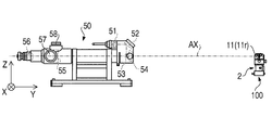
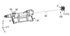
- FIG. 6 is a side view and a perspective view showing the configuration of the adjustment telescope 50.
- the deflection unit 100 is attached to a predetermined reference position, specifically, to a deflection unit mounting position (or a housing jig for adjustment work) in the housing of the optical device.
- a deflection unit mounting position or a housing jig for adjustment work
- FIG. 2 shows a part of the components incorporated in the adjustment telescope 50 by broken lines in order to schematically explain the configuration of the adjustment telescope 50.
- the adjustment telescope 50 for example, an alignment telescope ([November 2008 search], Internet, URL: reference) of Coastal Optical System Co., Ltd. is used.
- the adjustment telescope 50 is a case jig for adjustment work in which the optical axis of the telescope 50 is on the center axis AX of the optical device (or equivalently to the center axis AX) by calibration prior to the adjustment of the deflector 11. On the center axis).
- the adjustment telescope 50 includes a light source unit 51 that emits measurement light.
- the measurement light emitted from the light source unit 51 is folded back in turn by the folding mirrors 52 and 53, travels on the central axis AX, and irradiates the object to be measured disposed in front of the adjustment telescope 50 via the objective optical system 54. To do.
- the measurement light is reflected on the object to be measured and enters the objective optical system 54.
- the size of the folding mirror 53 is very small. Therefore, the reflected light from the object to be measured passes through the folding mirror 53 without substantially reducing the light amount due to the vignetting of the folding mirror 53 and forms an intermediate image on the reticle 55.
- the operator observes the reticle 55 and an image formed on the reticle 55 through the eyepiece optical system 56.
- the objective optical system 54 and the eyepiece optical system 56 are each shown as a single lens in FIG. 2, but are actually constituted by a plurality of lenses.
- the adjustment telescope 50 has a focusing knob 57.
- some lens groups move according to the amount of operation of the focusing knob 57 by the operator.
- the focal position of the objective optical system 54 is adjusted by moving the lens group in conjunction with the focusing knob 57.
- the focal position of the objective optical system 54 is adjusted in advance in the vicinity of the deflection surface 11r of the deflector 11 that is the component to be adjusted.
- the adjustment telescope 50 has a vertical adjustment micrometer 58 and a horizontal adjustment micrometer 59.
- the vertical adjustment micrometer 58 and the horizontal adjustment micrometer 59 are interlocked with the reticle 55.
- the reticle 55 moves in the Z direction or the X direction according to the operation amount of the vertical adjustment micrometer 58 or the horizontal adjustment micrometer 59 by the operator.
- FIG. 4 shows an example of the pattern of the reticle 55 that appears in the visual field range 60 of the telescope 50 when looking through the adjustment telescope 50.
- the reticle 55 is adjusted in advance to a position suitable for adjustment of the deflector 11 (for example, as shown in FIG. 4, the pattern center 55 c of the reticle 55 is positioned at the center of the visual field range 60).
- the deflection unit 100 has a precision stage 2 for fine adjustment in addition to the deflector 11.
- the fine adjustment precision stage 2 includes a general-purpose stage (for example, TSD-409C, TSD-409S, TSD-609C, TSD-609, manufactured by Sigma Koki Co., Ltd.) that finely adjusts the position or angle of the component to be adjusted in four axes. 609S etc. ([November 2008 search], Internet, URL: ⁇ http://www.sigma-koki.com/english/C/ManualStages/MultiAxezStages/TSD-XYZQ/TSD-XYZQ.html>) Is used.
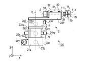
- FIG. 5 is a side view of the deflection unit 100 as viewed from the adjustment telescope 50 side.
- 6 and 7 are perspective views showing the configuration of the deflection unit 100.
- the ⁇ stage 20 ⁇ holds a deflector 11 that is a component to be adjusted.
- the Z stage 20z has a Z-axis block base 21z, a Z-axis micrometer 22z, and a Z-axis clamp 23z.
- the Z-axis block base 21z has a connecting surface (not shown) that moves so as to move up (or down) in the Z direction according to the amount of operation of the Z-axis micrometer 22z by the operator.
- An XY stage 20xy is connected to the connection surface. As the connecting surface moves, the XY stage 20xy connected to the connecting surface, the ⁇ stage 20 ⁇ connected to the XY stage 20xy, and the deflector 11 held by the ⁇ stage 20 ⁇ are integrated into the Z direction. Move to.
- the operator can finely adjust the position of the deflector 11 in the Z direction with respect to the center axis AX by operating the Z axis micrometer 22z.
- the connecting surface of the Z-axis block base 21z is prevented from moving in the Z direction by clamping the Z-axis clamp 23z.
- the XY stage 20xy has an XY-axis block base 21xy, an X-axis micrometer 22x, a Y-axis micrometer 22y, an XY-axis rectilinear stage 23xy, and an XY-axis clamp 24xy.
- the XY axis rectilinear stage 23xy moves straight in the X direction or the Y direction according to the amount of operation of the X axis micrometer 22x or the Y axis micrometer 22y by the operator.
- a ⁇ stage 20 ⁇ is connected to the XY axis linearly-moving stage 23xy.
- the ⁇ stage 20 ⁇ connected to the XY axis rectilinear stage 23xy and the deflector 11 held by the ⁇ stage 20 ⁇ move together in the X direction or the Y direction.
- the operator operates the X-axis micrometer 22x or the Y-axis micrometer 22y so that the position of the deflector 11 in the X direction with respect to the center axis AX or the Y direction of the deflector 11 with respect to the focal position of the adjustment telescope 50 is determined.
- the XY axis linearly moving stage 23xy is prevented from moving in the X direction or the Y direction by clamping the XY axis clamp 24xy.
- the ⁇ stage 20 ⁇ has a rotating block base 21 ⁇ , a rotating micrometer 22 ⁇ , a rotating stage 23 ⁇ , and a rotating clamp 24 ⁇ .
- the rotary stage 23 ⁇ rotates on the XY plane around the ⁇ axis indicated by the two-dot chain line in each of FIGS. 5 to 7 according to the amount of operation of the rotation micrometer 22 ⁇ by the operator.
- the deflector 11 held by the ⁇ stage 20 ⁇ rotates on the XY plane as the rotary stage 23 ⁇ rotates. That is, the operator can change the angle formed by the deflection surface 11r with respect to the central axis AX by operating the rotation micrometer 22 ⁇ .
- the rotary stage 23 ⁇ is prevented from rotating on the XY plane by clamping the rotary clamp 24 ⁇ .
- the heat sink 31 is screwed to the rotary stage 23 ⁇ with four screws 32.
- a cylindrical holding case 33 is sandwiched between the rotary stage 23 ⁇ and the heat sink 31.
- a chuck 34 is held at one end of the holding case 33.
- the deflector 11 is chucked on the chuck 34.
- an adhesive is poured between the deflector 11 and the chuck 34.
- a deflector driving actuator (not shown) connected to the chuck 34 is held.
- the deflector driving actuator is connected to a power supply device (both not shown) via a signal cable extending from the other end of the holding case 33, and a drive voltage is supplied from the power supply device.
- the heat sink 31 is required not only to hold the holding case 33 but also to efficiently suppress the heat generation of the deflector driving actuator, for example, an aluminum die-cast product having excellent heat release properties is suitable.
- the laser light incident on the deflecting surface 11r is deflected according to the change in the angle of the deflecting surface 11r accompanying the rotation of the ⁇ -axis center, and passes through the subsequent optical system of the optical device. To scan the surface to be scanned.
- the operator rotates the deflector 11 about the ⁇ axis so that the back surface 11 b of the deflector 11 (the surface opposite to the deflecting surface 11 r) faces the adjustment telescope 50. .
- the operator drives the deflector driving actuator to rotate the deflector 11 electrically or manually.
- the screw 32 is in a temporarily tightened state, play occurs between the holding case 33 and the space defined by the rotary stage 23 ⁇ and the heat sink 31.
- manual rotation of the holding case 33 is allowed. That is, the operator can manually rotate the deflector 11 together with the holding case 33 to adjust the rotation angle of the deflector 11 around the ⁇ axis.
- the screw 32 is finally tightened to fix the holding case 33 by sandwiching the rotary stage 23 ⁇ and the heat sink 31. Note that when the deflector 11 is rotated so that the back surface 11b is substantially directly opposed to the adjusting telescope 50, electrical rotation and manual rotation may be used in combination.
- An indicator 11i having a cross-shaped groove shape is formed on the back surface 11b of the deflector 11 by cutting with an end mill, for example.
- the intersection 11c of the lines forming the cross of the index 11i is located at the center of the back surface 11b.
- the back surface 11b of the deflector 11 and each side surface of the deflector 11 are not surfaces having the optical performance necessary for the optical device, and thus prevent unnecessary irregular reflection inside the optical device. Therefore, antireflection treatment is performed.
- the operator operates the X-axis micrometer 22x and the Z-axis micrometer 22z while looking through the adjustment telescope 50 to move the deflector 11 in the X direction or the Z direction.
- the operator finely adjusts the position of the deflector 11 in order to align the intersection 11c of the index 11i with the pattern center 55c of the reticle 55 of the adjustment telescope 50.
- the operator operates the Y-axis micrometer 22y to adjust the focus of the adjustment telescope 50 at the same time.
- the operator When the operator aligns the intersection 11c of the index 11i with the pattern center 55c of the reticle 55 of the adjusting telescope 50, the operator then drives the deflector driving actuator to rotate the deflector 11 about the ⁇ axis by 180 degrees. That is, the operator makes the deflection surface 11r of the deflector 11 substantially face the adjustment telescope 50 as shown in FIG.
- manual rotation of each holding case 33 may be used together as necessary.
- the operator preferably rotates the deflector 11 electrically or manually in consideration of the rotatable range of the deflector 11 by the actuator for driving the deflector.
- the deflector driving actuator is stopped at substantially the center of the rotatable range. Preferably there is.
- the operator turns on the light source 51 of the adjustment telescope 50 and irradiates the deflecting surface 11r of the deflector 11 with measurement light.
- the operator looks into the adjustment telescope 50 again and observes the reflected light of the measurement light irradiated on the deflection surface 11r.
- the operator rotates to adjust the deflection surface 11r to an appropriate angle, more specifically, to adjust the deflection surface 11r to an angle orthogonal to the central axis AX (in other words, parallel to the XZ plane).
- the deflector 11 is rotated on the XY plane by operating the micrometer 22 ⁇ .
- the operator finely adjusts the angle of the deflection surface 11r so that the reflected light returns to the pattern center 55c of the reticle 55.
- the deflection surface 11r is adjusted to a state orthogonal to the center axis AX with extremely high accuracy through the fine adjustment operation of the angle here.
- the position of the deflector when the position of the deflector is adjusted using the index, it is only necessary to rotate the deflector so that the back surface is directed to the adjusting telescope. Unlike the adjustment work conventionally performed by touching the deflector directly, it is not necessary to attach or remove a cover cap with an index covering the entire deflector from the deflector. For this reason, during the adjustment work of the deflector, the occurrence of the problem of damaging the deflecting surface or attaching dirt to the deflecting surface is suitably suppressed.
- the adjustment accuracy of the deflector cannot be lowered due to individual differences or attachment errors of the cover cap.
- the indicator 11 i is formed on the back surface 11 b of the deflector 11, and relative displacement from the deflector 11 cannot occur. That is, the adjustment accuracy of the deflector 11 is guaranteed by attaching the index 11i directly to the deflector 11.
- the adjustment method of the deflection unit and the deflector mounted on the optical apparatus according to the present invention is not limited to the above configuration or method, and various modifications are possible within the scope of the technical idea of the present invention.
- the adjustment work of the deflector 11 may be performed in the order of the angle adjustment of the deflection surface 11r and the position adjustment of the deflector 11.
- each adjustment operation of the position adjustment and the angle adjustment may be repeated a plurality of times until the deflector 11 is adjusted with high accuracy.
- the deflector 11 may be a low-reflective resin molded product in which, for example, a deflecting surface 11r is coated with a reflective film in view of manufacturability and cost reduction.
- the shape of the indicator 11i is not limited to a cross shape.
- the indicator 11i only needs to have a shape that allows the operator to specify the center of the back surface 11b of the deflector 11, for example.
- the index 11i is not limited to the groove shape, and may be a convex shape protruding from the back surface 11b, for example.
- the index 11i does not need to have a shape formed on the back surface 11b, and may be a mark (for example, a cross mark) printed on the back surface 11b, for example.
- the index 11i may not be on the back surface 11b of the deflector 11, but may be provided by a part that is configured to be detachable from the deflector 11.
- FIG. 8 shows a configuration of a component having the index 11i (a back cover 3cp that covers the back surface 11b of the deflector 11).
- FIG. 8A is a side sectional view of the deflector 11 equipped with the back cover 3cp.
- FIG. 8B is a diagram showing the index surface 3s of the back cover 3cp to which the index 11i is attached (or formed).
- the back cover 3cp is a resin molded product formed of a resin having a relatively low Young's modulus, for example. As shown in FIG. 8A, the back surface cover 3 cp has an engaging claw portion 3 a that engages with the peripheral portion of the deflector 11.
- the engaging claw portions 3a are formed along each side of the back cover 3cp (four in total because the back cover 3cp is formed in a substantially rectangular shape). Each engagement claw portion 3 a is engaged with the peripheral portion of the deflector 11 while being hooked on each side of the deflector 11 and being elastically deformed.
- the back surface cover 3cp covers the entire surface of each side surface of the deflector 11 and the entire surface of the back surface 11b while exposing the effective region of the deflecting surface 11r (that is, the region actually used for laser beam scanning). It is attached to the deflector 11 in a state.
- the back cover 3cp is formed of a resin having a low reflectance so as to prevent unnecessary irregular reflection inside the optical apparatus.
- the adjustment of the deflector 11 is performed in the same manner as already described in a state where the back cover 3cp is mounted on the deflector 11. That is, the operator makes the index surface 3 s of the back cover 3 cp substantially face the adjustment telescope 50, and while looking through the adjustment telescope 50, the intersection 11 c of the index 11 i of the back cover 3 cp is the pattern of the reticle 55 of the adjustment telescope 50. In order to adjust to the center 55c, the position of the deflector 11 is finely adjusted. Next, the operator makes the deflection surface 11r exposed from the back cover 3cp substantially face the adjustment telescope 50, and finely adjusts the angle of the deflection surface 11r while looking through the adjustment telescope 50 again.
- the back cover 3cp may be removed from the deflector 11 after the adjustment work of the deflector 11 is completed, or may remain attached to the deflector 11.
- the back cover 3cp does not rub against the deflection surface 11 during attachment or removal, and therefore does not damage the deflection surface 11 or attach dirt to the deflection surface. Note that, when the back cover 3cp is continuously mounted even after the adjustment work of the deflector 11 is completed, there is an advantage that it is not necessary to perform antireflection processing on each side surface of the deflector 11 and each surface of the back surface 11b. Therefore, the modification shown in FIG. 8 is effective when position adjustment is performed on an existing deflector in which any adjustment processing is not performed on the back surface.
Landscapes
- Physics & Mathematics (AREA)
- General Physics & Mathematics (AREA)
- Optics & Photonics (AREA)
- Mechanical Optical Scanning Systems (AREA)
Abstract
偏向器の偏向面の損傷や汚れ付着を有効に避けつつも偏向器を高精度に調整するため、偏向器調整方法を、偏向器の位置又は角度を調整できるように該偏向器を保持した基台を所定の基準位置に配置する基台配置ステップと、基台が基準位置に配置されたとき、偏向器のレーザー光を偏向する偏向面の裏面が所定の測定機に略正対するように該偏向器を回転させる第一の偏向器回転ステップと、裏面が有する指標の特定位置が測定機の基準軸上に合うように、基台による偏向器の位置調整を行う偏向器位置調整ステップと、偏向面が測定機に略正対するように偏向器を回転させる第二の偏向器回転ステップと、測定機により照射された測定光の偏向面上での反射光が該測定機の基準軸上に戻るように、基台による偏向器の角度調整を行う偏向器角度調整ステップを含む方法とした。
Description
この発明は、被走査面上にレーザー光を走査する光学機器に搭載される偏向器の調整を行う偏向器調整方法、および該方法による調整を行うのに適した偏向器を持つ偏向ユニットに関する。
レーザープリンタやプロジェクタ等の光学機器には、例えば特開昭59-38723号公報に開示されるように、被走査面上に走査線を描画するため、光源から照射されたレーザー光を偏向する偏向器が搭載されている。偏向器は、レーザー光が被走査面上に精度良く走査されるよう、精密な調整工程を経て光学機器の筐体に取り付けられている。
図1は、被調整部品である偏向器1(例えばガルバノミラー)を搭載した偏向ユニット10の構成を示す斜視図である。以下、図1を参照して、従来実施されている調整工程を説明する。調整工程において偏向ユニット10は、図示省略された光学機器の筐体又は調整用治具に取り付けられる。図1又は以降の各図中一点鎖線は、偏向ユニットが搭載される光学機器の中心軸(光軸)AXである。本明細書において、中心軸AXと平行な方向を「Y方向」と定義し、Y方向と直交し且つ互いに直交する二方向を「X方向」、「Z方向」と定義する。
偏向器1の調整には、図示省略された調整用望遠鏡が用いられる。調整用望遠鏡は、偏向器1の調整に先立つキャリブレーションにより、該望遠鏡の光軸が光学機器の中心軸AX上に合わせ込まれている。偏向ユニット10は、偏向器1の位置又は角度を4軸方向で微調整する微調整用精密ステージ2を有している。微調整用精密ステージ2は、偏向器1をX方向、Y方向、Z方向に移動自在に、かつXY平面上で回転自在に保持している。調整工程において作業者は、微調整用精密ステージ2を操作して偏向器1の位置調整や角度調整を行う。
調整工程における作業者の具体的作業は次の通りである。作業者は、偏向器1全体をカバーするカバーキャップ3を偏向器1に取り付ける。カバーキャップ3の外面には、十字型の指標3iが付されている。作業者は、偏向器1の偏向面1rの中心を中心軸AXに合わせるべく、調整用望遠鏡のアイピースを覗きながら微調整用精密ステージ2を操作して、偏向器1を(主にX方向又はZ方向に)移動させる。作業者は、指標3iの中心(十字をなす各線の交点)が該望遠鏡のレチクルの中心に合うように偏向器1の位置を微調整する。作業者は、次いで、偏向器1からカバーキャップ3を取り外す。その上で調整用望遠鏡の光源を点灯させて、偏向器1の偏向面1r上に測定光を照射させる。作業者は、調整用望遠鏡のアイピースを再び覗いて、偏向面1r上に照射された測定光の反射光を観察する。作業者は、偏向面1rを適切な角度に、具体的には偏向面1rを中心軸AXと直交する角度に(別の表現によればXZ平面と平行になるように)調整すべく、微調整用精密ステージ2を操作して偏向器1をXY平面上で回転させる。作業者は、反射光がレチクルの中心に戻るように偏向面1rの角度を微調整する。以上に説明された調整工程を経て、偏向器1は、適切な位置および角度に調整される。
作業者は、このような方法で偏向器1の調整を行う場合、偏向器1の位置調整や偏向面1rの角度調整を行う都度、指標3iの取り付け又は取り外しを行う必要がある。これは、作業者にとって煩雑な作業である。また、かかる調整方法では、指標3iの個体差や取付誤差に起因して、偏向器1の調整精度が低下する点が問題視されている。さらに、指標3iを取り付けし又は取り外す際に、指標3iの内壁が偏向面1rに擦れて、偏向面1rを損傷させたり偏向面1rに汚れを付着させたりする点も問題視されている。このような偏向面1rの損傷や汚れ付着等は、偏向器1の光学性能を低下させる要因であり、有効に避けることが望まれている。
なお、偏向器を搭載する光学機器そのものに関する文献は多々あるものの、以上に述べた背景技術および問題点に関する適切な先行技術文献を見出すことはできなかった。
本発明は上記の事情に鑑みてなされたものであり、その目的とするところは、偏向面の損傷や汚れ付着を有効に避けつつも偏向器を高精度に調整するのに好適な偏向器調整方法、および該方法による調整を行うのに適した偏向器を持つ偏向ユニットを提供することである。
上記の課題を解決する本発明の一形態に係る偏向器調整方法は、被走査面上にレーザー光を走査する光学機器に搭載される偏向器の調整を行う方法であり、以下の特徴を有する。すなわち、かかる偏向器調整方法は、偏向器の位置又は角度を調整できるように該偏向器を保持した基台を所定の基準位置に配置する基台配置ステップと、基台が基準位置に配置されたとき、偏向器のレーザー光を偏向する偏向面の裏面が所定の測定機に略正対するように該偏向器を回転させる第一の偏向器回転ステップと、裏面が有する指標の特定位置が測定機の基準軸上に合うように、基台による偏向器の位置調整を行う偏向器位置調整ステップと、偏向面が測定機に略正対するように偏向器を回転させる第二の偏向器回転ステップと、測定機により照射された測定光の偏向面上での反射光が該測定機の基準軸上に戻るように、基台による偏向器の角度調整を行う偏向器角度調整ステップを含むことを特徴としている。
本発明に係る偏向器調整方法によれば、指標を用いた偏向器の位置調整を行う際、偏向器を回転させて該偏向器の裏面を測定機に向けるだけでよい。偏向器に直接手を触れたり、或いは従来実施されていた調整作業と異なり、指標付きのカバーキャップを偏向器に取り付けたり偏向器から取り外したりする必要がない。そのため、偏向器の調整作業時に、偏向面を損傷させたり偏向面に汚れを付着させたりする問題の発生が好適に抑えられることとなる。さらに、指標付きのカバーキャップ自体を使用しないため、該カバーキャップの個体差や取付誤差に起因する偏向器の調整精度の低下が起こり得ない。別の側面によれば、偏向器自体が指標を有するため、指標と偏向器との相対的なズレが生じ得ない。
ここで指標は、例えば偏向器の裏面から臨んだときに所定の模様をなすように該裏面に形成された溝部又は凸部であってもよく、或いは該裏面にプリントされた所定のマークであってもよい。
また、指標は、偏向面を露出するカバーを偏向器に装着したときに、裏面を覆う該カバーの面に付された模様、又は形成された模様であってもよい。
偏向器の裏面には光学機器内部の不要な乱反射等を防ぐべく、反射防止処理を施すことが望ましい。
また、第一の偏向器回転ステップ又は第二の偏向器回転ステップにおいて、偏向器を基台に実装されたアクチュエータを駆動させて電気的に回転させるか、又は該偏向器を手動で回転させるかし、或いは該アクチュエータによる電気的回転と手動による回転とを併用して該偏向器を回転させるかすることにより、該第二の偏向器回転ステップの実行時に該偏向面を測定機に略正対させたとき、該アクチュエータを該アクチュエータの回転可能範囲の略中心で停止させた状態にすることが好ましい。
また、上記の課題を解決する本発明の一形態に係る偏向ユニットは、被走査面上にレーザー光を走査する光学機器に搭載されるユニットであり、以下の特徴を有する。すなわち、かかる偏向ユニットは、レーザー光を偏向する偏向面を有する偏向器と、偏向器の位置又は角度を調整できるように該偏向器を保持した基台とを有している。当該偏向器は、基台による偏向器の位置調整を行う際に、所定の測定機の基準軸上に合わせられるべき特定位置を持つ指標を、該偏向面の裏面に有することを特徴としている。
また、上記の課題を解決する本発明の別の形態に係る偏向ユニットは、被走査面上にレーザー光を走査する光学機器に搭載されるユニットであり、以下の特徴を有する。すなわち、かかる偏向ユニットは、レーザー光を偏向する偏向面を有する偏向器と、偏向器の位置又は角度を調整できるように該偏向器を保持した基台と、偏向面を露出しつつも該偏向面の裏面を覆うように偏向器に装着されるカバーとを有している。当該カバーは、偏向器の裏面を覆う該カバーの面上に、基台による偏向器の位置調整を行う際に、所定の測定機の基準軸上に合わせられるべき特定位置を持つ指標を有することを特徴としている。
以下、図面を参照して、本発明に係る光学機器に搭載される偏向ユニットおよび偏向器の調整方法を説明する。
図2、図3はそれぞれ、本発明の実施形態の被調整部品である偏向器11(ガルバノミラーであり、金属製の矩形板)を搭載する偏向ユニット100、および偏向器11の調整に用いられる調整用望遠鏡50の構成を示す側面図、斜視図である。偏向ユニット100は、偏向器11の調整を行うにあたり、所定の基準位置に、具体的には光学機器の筐体内の偏向ユニット取付位置(又は調整作業用の筐体治具)に取り付けられる。但し、図2、図3を含む各図においては、図面を明瞭化するため、光学機器の筐体(又は調整作業用の筐体治具)の図示を省略している。また、図2は、調整用望遠鏡50の構成を概略的に説明するため、調整用望遠鏡50に内蔵される一部の部品を破線で示している。
調整用望遠鏡50には、例えばコースタル・オプティカル・システム社のアライメントテレスコープ([平成20年11月検索]、インターネット、URL:参照)が使用される。調整用望遠鏡50は、偏向器11の調整に先立つキャリブレーションにより、該望遠鏡50の光軸が光学機器の中心軸AX上に(又は中心軸AXと等価関係にある調整作業用の筐体治具の中心軸上に)合わせ込まれている。
図2に示されるように、調整用望遠鏡50は、測定光を照射する光源部51を有している。光源部51から照射された測定光は、折返しミラー52、53に順に折り返されて中心軸AX上を進み、対物光学系54を介して調整用望遠鏡50の前方に配置された被測定物を照射する。かかる測定光は、被測定物上で反射されて、対物光学系54に入射される。ここで折返しミラー53のサイズは微小である。そのため、被測定物からの反射光は、折返しミラー53のケラレによる光量低下が実質的に生じること無く折返しミラー53を通過して、レチクル55上に中間像を結ぶ。作業者は、接眼光学系56を通じてレチクル55およびレチクル55上に結ばれる像を観察する。なお、対物光学系54、接眼光学系56はそれぞれ、図2中単レンズで示されているが、実際には複数枚のレンズによって構成されている。
図2又は図3に示されるように、調整用望遠鏡50は、フォーカシングノブ57を有している。対物光学系54は、作業者によるフォーカシングノブ57の操作量に応じて、一部のレンズ群が移動する。フォーカシングノブ57に連動したレンズ群の移動により、対物光学系54の焦点位置の調節がなされる。本実施形態において対物光学系54の焦点位置は、被調整部品である偏向器11の偏向面11r近傍に予め調節されている。
また、調整用望遠鏡50は、垂直方向調整用マイクロメータ58、水平方向調整用マイクロメータ59を有している。垂直方向調整用マイクロメータ58、水平方向調整用マイクロメータ59は、レチクル55と連動している。レチクル55は、作業者による垂直方向調整用マイクロメータ58又は水平方向調整用マイクロメータ59の操作量に応じて、Z方向又はX方向に移動する。図4に、調整用望遠鏡50を覗いたときの該望遠鏡50の視野範囲60に写るレチクル55のパターンの一例を示す。レチクル55は、偏向器11の調整に適した位置(例えば図4に示されるようにレチクル55のパターン中心55cが視野範囲60の中心に位置するよう)に予め調節されている。
偏向ユニット100は、偏向器11に加えて微調整用精密ステージ2を有している。微調整用精密ステージ2には、被調整部品の位置又は角度を4軸方向で微調整する汎用的なステージ(例えばシグマ光機株式会社のTSD-409C、TSD-409S、TSD-609C、TSD-609S等([平成20年11月検索]、インターネット、URL:<http://www.sigma-koki.com/english/C/ManualStages/MultiAxezStages/TSD-XYZQ/TSD-XYZQ.html>参照))が使用される。
以下、本実施形態の偏向ユニット100に利用されている微調整用精密ステージ2について概略的に説明する。図5は、調整用望遠鏡50側から臨んだ偏向ユニット100の側視図である。また、図6、図7の各図は、偏向ユニット100の構成を示す斜視図である。図5から図7の各図に示されるように、微調整用精密ステージ2は、該ステージ2の下側から順に、Zステージ20z、XYステージ20xy、θステージ20θの各種ステージが積層され、連結した構成を有している。θステージ20θには被調整部品である偏向器11が保持されている。
図5に示されるように、Zステージ20zは、Z軸ブロック基台21z、Z軸マイクロメータ22z、Z軸クランプ23zを有している。Z軸ブロック基台21zは、作業者によるZ軸マイクロメータ22zの操作量に応じて、Z方向に迫り上がる(又は下がる)ように移動する連結面(不図示)を有している。かかる連結面にはXYステージ20xyが連結されている。連結面の移動に伴い、該連結面に連結されたXYステージ20xy、XYステージ20xy上に連結されたθステージ20θ、さらには、θステージ20θに保持された偏向器11が一体となってZ方向に移動する。すなわち、作業者は、Z軸マイクロメータ22zを操作して、中心軸AXに対する偏向器11のZ方向の位置を微調整することができる。なお、Z軸ブロック基台21zの連結面は、Z軸クランプ23zをクランプすることにより、Z方向の移動が阻止される。
XYステージ20xyは、XY軸ブロック基台21xy、X軸マイクロメータ22x、Y軸マイクロメータ22y、XY軸直進型ステージ23xy、XY軸クランプ24xyを有している。XY軸直進型ステージ23xyは、作業者によるX軸マイクロメータ22x又はY軸マイクロメータ22yの操作量に応じて、X方向又はY方向に直進移動する。XY軸直進型ステージ23xyにはθステージ20θが連結されている。XY軸直進型ステージ23xyの直進移動に伴い、XY軸直進型ステージ23xyに連結されたθステージ20θ、およびθステージ20θに保持された偏向器11が一体となってX方向又はY方向に直進移動する。すなわち、作業者は、X軸マイクロメータ22x又はY軸マイクロメータ22yを操作して、中心軸AXに対する偏向器11のX方向の位置、又は調整用望遠鏡50の焦点位置に対する偏向器11のY方向の位置を微調整することができる。なお、XY軸直進型ステージ23xyは、XY軸クランプ24xyをクランプすることにより、X方向又はY方向の移動が阻止される。
θステージ20θは、回転ブロック基台21θ、回転用マイクロメータ22θ、回転型ステージ23θ、回転用クランプ24θを有している。回転型ステージ23θは、作業者による回転用マイクロメータ22θの操作量に応じて、図5から図7の各図中二点鎖線で示されるα軸を中心にXY平面上で回転する。θステージ20θに保持された偏向器11は、回転型ステージ23θの回転に伴ってXY平面上で回転する。すなわち、作業者は、回転用マイクロメータ22θを操作して、中心軸AXに対して偏向面11rがなす角度を変えることができる。なお、回転型ステージ23θは、回転用クランプ24θをクランプすることにより、XY平面上の回転が阻止される。
回転型ステージ23θには、ヒートシンク31が4本のネジ32によりネジ止めされている。回転型ステージ23θとヒートシンク31との間には、円筒状の保持ケース33が狭持されている。保持ケース33の一端にはチャック34が保持されている。チャック34には、偏向器11がチャッキングされている。チャック34による保持力をより一層高めるため、偏向器11とチャック34との間には接着剤が流し込まれている。
保持ケース33の内部には、チャック34に連結された偏向器駆動用アクチュエータ(不図示)が保持されている。偏向器駆動用アクチュエータは、保持ケース33の他端から延びる信号ケーブルを介して電源装置(ともに図示省略)に接続されており、該電源装置から駆動電圧が供給される。偏向器駆動用アクチュエータの駆動により、チャック34、およびチャック34にチャッキングされた偏向器11が、図5から図7の各図中二点鎖線で示されるβ軸を中心として、保持ケース33に対して回転する。
なお、ヒートシンク31には、保持ケース33を保持するだけでなく偏向器駆動用アクチュエータの発熱を効率良く抑える役割も要求されるため、例えば熱放出性に優れたアルミダイカスト品が適している。光学機器を実際に使用する際、偏向面11rに入射されるレーザー光は、β軸中心の回転に伴う偏向面11rの角度変化に応じて偏向されて、光学機器が持つ後段の光学系を介して被走査面上を走査する。
次に、本実施形態における偏向器11の具体的調整作業を説明する。作業者は、図6に示されるように、偏向器11の裏面11b(偏向面11rの反対側の面)を調整用望遠鏡50に略正対させるべく、偏向器11をβ軸中心に回転させる。このとき作業者は、偏向器駆動用アクチュエータを駆動させて電気的に、又は手動により偏向器11を回転させる。ここでネジ32が仮締め状態にあるとき、回転型ステージ23θとヒートシンク31とが規定するスペースと、保持ケース33との間にあそびが生じる。そのため、保持ケース33の手動によるβ軸中心の回転が許容される。すなわち、作業者は、偏向器11を保持ケース33ごと手動で回転させて、偏向器11のβ軸中心の回転角度を調整することができる。手動による回転作業の後、ネジ32は、回転型ステージ23θとヒートシンク31との狭持により保持ケース33を固定するため、本締めされる。なお、偏向器11を回転させて裏面11bを調整用望遠鏡50に略正対させるとき、電気的回転と手動による回転とを併用しても構わない。
偏向器11の裏面11bには、例えばエンドミルによる切削加工により十字型溝形状である指標11iが形成されている。指標11iの十字をなす各線の交点11cは、裏面11bの中心に位置している。なお、偏向器11における裏面11bおよび偏向器11の各側面(つまり、偏向面11r以外の面)は、光学機器に必要な光学性能を持つ面でないため、光学機器内部の不要な乱反射等を防ぐべく、反射防止処理が施されている。
作業者は、調整用望遠鏡50を覗きながらX軸マイクロメータ22x、Z軸マイクロメータ22zを操作して、偏向器11をX方向又はZ方向に移動させる。作業者は、指標11iの交点11cを調整用望遠鏡50のレチクル55のパターン中心55cに合わせるため、偏向器11の位置を微調整する。作業者は、指標11iがぼやけて観察される場合にはY軸マイクロメータ22yを操作して、調整用望遠鏡50のピント調整も併せて行う。
作業者は、指標11iの交点11cを調整用望遠鏡50のレチクル55のパターン中心55cに合わせ込むと次いで、偏向器駆動用アクチュエータを駆動させて、偏向器11をβ軸中心に180度回転させる。すなわち、作業者は、図7に示されるように、偏向器11の偏向面11rを調整用望遠鏡50に略正対させる。このときの作業には、手動による保持ケース33ごとの回転を必要に応じて併用してもよい。なお、作業者は、偏向器駆動用アクチュエータによる偏向器11の回転可能範囲を鑑みて、偏向器11を電気的に回転させたり手動により回転させたりすることが好ましい。具体的には、交点11cとパターン中心55cとを一致させて偏向面11rを調整用望遠鏡50に略正対させたときに、偏向器駆動用アクチュエータが回転可能範囲の略中心で停止した状態にあることが好ましい。
作業者は、調整用望遠鏡50の光源51を点灯させて、偏向器11の偏向面11rに測定光を照射させる。作業者は、調整用望遠鏡50を再び覗いて、偏向面11rに照射された測定光の反射光を観察する。作業者は、偏向面11rを適切な角度に、具体的には偏向面11rを中心軸AXと直交する角度に(別の表現によればXZ平面と平行になるように)調整すべく、回転用マイクロメータ22θを操作して偏向器11をXY平面上で回転させる。作業者は、反射光がレチクル55のパターン中心55cに戻るように偏向面11rの角度を微調整する。偏向面11rは、ここでの角度の微調整作業を経て、極めて高精度に中心軸AXに直交した状態に調整される。
このように本実施形態によれば、指標を用いた偏向器の位置調整を行う際には、偏向器を回転させて裏面を調整用望遠鏡に向けるだけでよい。偏向器に直接手を触れたり、或いは従来実施されていた調整作業と異なり、偏向器全体をカバーする指標付きのカバーキャップを偏向器に取り付けたり偏向器から取り外したりする必要がない。そのため、偏向器の調整作業時に、偏向面を損傷させたり偏向面に汚れを付着させたりする問題の発生が好適に抑えられることとなる。
さらに、本実施形態によれば、上記カバーキャップ自体を使用しないため、該カバーキャップの個体差や取付誤差に起因する偏向器の調整精度の低下が起こり得ない。別の側面によれば、指標11iは、偏向器11の裏面11b自体に形成されており、偏向器11との相対的なズレが生じ得ない。すなわち、指標11iを偏向器11に直接付すことにより、偏向器11の調整精度が保障されている。
以上が本発明の実施形態である。本発明に係る光学機器に搭載される偏向ユニットおよび偏向器の調整方法は、上記の構成又は方法に限定されるものではなく、本発明の技術的思想の範囲において様々な変形が可能である。例えば偏向器11の調整作業は、偏向面11rの角度調整、偏向器11の位置調整の順に行われてもよい。また、当該位置調整と角度調整の各調整作業は、偏向器11が高精度に調整されるまで複数回繰り返し行われてもよい。
偏向器11は、製造容易性やコストダウンを鑑みて、例えば偏向面11rに反射膜がコーティングされた低反射性の樹脂成形品であってもよい。
また、指標11iの形は十字型に限定されない。指標11iは、例えば作業者が偏向器11の裏面11bの中心を特定できる形を有していればよい。また、指標11iは溝形状に限らず、例えば裏面11bから突出した凸形状であってもよい。さらに、指標11iは、裏面11bに形成された形状である必要はなく、例えば裏面11bにプリントされたマーク(例えば十字マーク)であってもよい。
また、指標11iは、偏向器11の裏面11b上に無く、偏向器11に着脱自在に構成された部品が有していてもよい。図8に、指標11iを有する部品(偏向器11の裏面11bをカバーする裏面カバー3cp)の構成を示す。図8(a)は、かかる裏面カバー3cpを装着した偏向器11の側断面図である。また、図8(b)は、指標11iが付された(又は形成された)裏面カバー3cpの指標面3sを示す図である。
裏面カバー3cpは、例えばヤング率が比較的低い樹脂によって成形された樹脂成形品である。図8(a)に示されるように、裏面カバー3cpは、偏向器11の周辺部に係合する係合爪部3aを有している。係合爪部3aは、裏面カバー3cpの各辺沿いに(裏面カバー3cpが略矩形状に形成されているため合計4つ)形成されている。各係合爪部3aは、偏向器11の各辺に引っ掛けられて弾性変形されつつ、偏向器11の周辺部に係合される。これにより、裏面カバー3cpは、偏向面11rの有効領域(つまり、レーザー光の走査に実際に使用される領域)を露出させつつ、偏向器11の各側面および裏面11bの各面全域に覆い被さる状態で偏向器11に装着される。なお、裏面カバー3cpは、光学機器内部の不要な乱反射等を防ぐべく、反射率の低い樹脂によって成形されている。
偏向器11の調整は、裏面カバー3cpが偏向器11に装着された状態で、既に説明された方法と同じ方法で行われる。すなわち、作業者は、裏面カバー3cpの指標面3sを調整用望遠鏡50に略正対させ、調整用望遠鏡50を覗きながら裏面カバー3cpの指標11iの交点11cを調整用望遠鏡50のレチクル55のパターン中心55cに合わせるため、偏向器11の位置を微調整する。作業者は、次いで、裏面カバー3cpから露出された偏向面11rを調整用望遠鏡50に略正対させ、調整用望遠鏡50を再び覗きながら偏向面11rの角度を微調整する。
裏面カバー3cpは偏向器11の調整作業終了後に、偏向器11から取り外されてもよく、或いは偏向器11に装着されたままでもよい。裏面カバー3cpは、取付時又は取り外し時の何れにおいても偏向面11と擦れないため、偏向面11を損傷させたり偏向面に汚れを付着させたりしない。なお、偏向器11の調整作業終了後も裏面カバー3cpを装着し続ける場合、偏向器11の各側面および裏面11bの各面に反射防止処理を施す必要がないといったメリットがある。よって、図8に示す変形例は、裏面に調整用の加工が何ら施されていない既存の偏向器に対して位置調整を行う場合に有効である。
Claims (11)
- 被走査面上にレーザー光を走査する光学機器に搭載される偏向器の調整を行う偏向器調整方法において、
前記偏向器の位置又は角度を調整できるように該偏向器を保持した基台を所定の基準位置に配置する基台配置ステップと、
前記基台が前記基準位置に配置されたとき、前記偏向器の前記レーザー光を偏向する偏向面の裏面が所定の測定機に略正対するように該偏向器を回転させる第一の偏向器回転ステップと、
前記裏面が有する指標の特定位置が前記測定機の基準軸上に合うように、前記基台による前記偏向器の位置調整を行う偏向器位置調整ステップと、
前記偏向面が前記測定機に略正対するように前記偏向器を回転させる第二の偏向器回転ステップと、
前記測定機により照射された測定光の前記偏向面上での反射光が該測定機の基準軸上に戻るように、前記基台による前記偏向器の角度調整を行う偏向器角度調整ステップと、
を含むことを特徴とする偏向器調整方法。 - 前記指標は、前記裏面から臨んだときに所定の模様をなすように該裏面に形成された溝部又は凸部であることを特徴とする、請求項1に記載の偏向器調整方法。
- 前記指標は、前記裏面にプリントされた所定のマークであることを特徴とする、請求項1に記載の偏向器調整方法。
- 前記指標は、前記偏向面を露出するカバーを前記偏向器に装着したときに、前記裏面を覆う該カバーの面に付された模様、又は形成された模様であることを特徴とする、請求項1に記載の偏向器調整方法。
- 前記裏面に反射防止処理を施すことを特徴とする、請求項1から請求項4の何れかに記載の偏向器調整方法。
- 前記第一の偏向器回転ステップ又は前記第二の偏向器回転ステップにおいて、前記偏向器を前記基台に実装されたアクチュエータを駆動させて電気的に回転させるか、又は該偏向器を手動で回転させるかし、或いは該アクチュエータによる電気的回転と手動による回転とを併用して該偏向器を回転させるかすることにより、該第二の偏向器回転ステップの実行時に該偏向面を前記測定機に略正対させたとき、該アクチュエータを該アクチュエータの回転可能範囲の略中心で停止させた状態にすることを特徴とする、請求項1から請求項5の何れかに記載の偏向器調整方法。
- 被走査面上にレーザー光を走査する光学機器に搭載される偏向ユニットにおいて、
前記レーザー光を偏向する偏向面を有する偏向器と、
前記偏向器の位置又は角度を調整できるように該偏向器を保持した基台と、
を有し、
前記基台による前記偏向器の位置調整を行う際に、所定の測定機の基準軸上に合わせられるべき特定位置を持つ指標を、前記偏向面の裏面に有することを特徴とする偏向ユニット。 - 前記指標は、前記裏面から臨んだときに所定の模様をなすように該裏面に形成された溝部又は凸部であることを特徴とする、請求項7に記載の偏向ユニット。
- 前記指標は、前記裏面にプリントされた所定のマークであることを特徴とする、請求項7に記載の偏向ユニット。
- 被走査面上にレーザー光を走査する光学機器に搭載される偏向ユニットにおいて、
前記レーザー光を偏向する偏向面を有する偏向器と、
前記偏向器の位置又は角度を調整できるように該偏向器を保持した基台と、
前記偏向面を露出しつつも該偏向面の裏面を覆うように前記偏向器に装着されるカバーと、
を有し、
前記裏面を覆う前記カバーの面上に、前記基台による前記偏向器の位置調整を行う際に、所定の測定機の基準軸上に合わせられるべき特定位置を持つ指標を有することを特徴とする偏向ユニット。 - 前記裏面に反射防止処理を施すことを特徴とする、請求項7から請求項10の何れかに記載の偏向ユニット。
Priority Applications (2)
| Application Number | Priority Date | Filing Date | Title |
|---|---|---|---|
| PCT/JP2008/071089 WO2010058463A1 (ja) | 2008-11-20 | 2008-11-20 | 偏向器調整方法、および偏向ユニット |
| JP2010539074A JP5249348B2 (ja) | 2008-11-20 | 2008-11-20 | 偏向器調整方法、および偏向ユニット |
Applications Claiming Priority (1)
| Application Number | Priority Date | Filing Date | Title |
|---|---|---|---|
| PCT/JP2008/071089 WO2010058463A1 (ja) | 2008-11-20 | 2008-11-20 | 偏向器調整方法、および偏向ユニット |
Publications (1)
| Publication Number | Publication Date |
|---|---|
| WO2010058463A1 true WO2010058463A1 (ja) | 2010-05-27 |
Family
ID=42197910
Family Applications (1)
| Application Number | Title | Priority Date | Filing Date |
|---|---|---|---|
| PCT/JP2008/071089 Ceased WO2010058463A1 (ja) | 2008-11-20 | 2008-11-20 | 偏向器調整方法、および偏向ユニット |
Country Status (2)
| Country | Link |
|---|---|
| JP (1) | JP5249348B2 (ja) |
| WO (1) | WO2010058463A1 (ja) |
Cited By (1)
| Publication number | Priority date | Publication date | Assignee | Title |
|---|---|---|---|---|
| CN117123914A (zh) * | 2023-09-19 | 2023-11-28 | 广东中科微精光子制造科技有限公司 | 光路调节装置及二维声光偏转装置 |
Citations (3)
| Publication number | Priority date | Publication date | Assignee | Title |
|---|---|---|---|---|
| JPS5938723A (ja) * | 1982-08-28 | 1984-03-02 | Canon Inc | 光走査装置 |
| JP2005303206A (ja) * | 2004-04-15 | 2005-10-27 | Nikon Corp | ミラー及び露光装置 |
| JP2007078722A (ja) * | 2005-09-09 | 2007-03-29 | Fuji Xerox Co Ltd | 光走査装置 |
-
2008
- 2008-11-20 JP JP2010539074A patent/JP5249348B2/ja not_active Expired - Fee Related
- 2008-11-20 WO PCT/JP2008/071089 patent/WO2010058463A1/ja not_active Ceased
Patent Citations (3)
| Publication number | Priority date | Publication date | Assignee | Title |
|---|---|---|---|---|
| JPS5938723A (ja) * | 1982-08-28 | 1984-03-02 | Canon Inc | 光走査装置 |
| JP2005303206A (ja) * | 2004-04-15 | 2005-10-27 | Nikon Corp | ミラー及び露光装置 |
| JP2007078722A (ja) * | 2005-09-09 | 2007-03-29 | Fuji Xerox Co Ltd | 光走査装置 |
Cited By (1)
| Publication number | Priority date | Publication date | Assignee | Title |
|---|---|---|---|---|
| CN117123914A (zh) * | 2023-09-19 | 2023-11-28 | 广东中科微精光子制造科技有限公司 | 光路调节装置及二维声光偏转装置 |
Also Published As
| Publication number | Publication date |
|---|---|
| JPWO2010058463A1 (ja) | 2012-04-12 |
| JP5249348B2 (ja) | 2013-07-31 |
Similar Documents
| Publication | Publication Date | Title |
|---|---|---|
| US9041940B2 (en) | Three-dimensional shape measuring apparatus | |
| JP5230236B2 (ja) | 露光装置 | |
| JP3694828B2 (ja) | フォトリソグラフマスク修復のためのレーザ投射システム及び方法 | |
| CN101298117B (zh) | 激光加工装置 | |
| CN1339708A (zh) | 光学部件的连接器件以及使用该器件的光学模块 | |
| US6060684A (en) | Laser beam machine with mode conversion | |
| JP2010502003A (ja) | マイクロリソグラフィ投影露光装置のための照明システム | |
| JP5804881B2 (ja) | 直接描画露光装置用半導体レーザモジュール | |
| CN1145540C (zh) | 激光加工装置 | |
| US20100128237A1 (en) | Driving apparatus, exposure apparatus, and device manufacturing method | |
| JP5249348B2 (ja) | 偏向器調整方法、および偏向ユニット | |
| JP2000343257A (ja) | 戻り光除去方法と装置 | |
| JP5611016B2 (ja) | 露光装置、露光方法、及び表示用パネル基板の製造方法 | |
| CN113497400B (zh) | 一种高精度激光器组装设备以及激光器组装方法 | |
| KR101536684B1 (ko) | 대형 광학계 정렬 시스템 | |
| US20230069195A1 (en) | Camera module manufacturing device | |
| JP5473880B2 (ja) | 露光装置、露光方法、及び表示用パネル基板の製造方法 | |
| JP5154661B2 (ja) | 光学部品調整方法、および光学部品調整システム | |
| JP4271103B2 (ja) | 大型望遠鏡用イメージロテータ装置の光学系駆体の組み立て調整方法および大型望遠鏡用イメージロテータ装置の製造方法 | |
| KR102001203B1 (ko) | 광학부재 마운트 장치 및 이를 포함하는 레이저 장치 | |
| JP3397581B2 (ja) | 射出光学装置 | |
| US7826070B2 (en) | Scanning optical system adjusting device and scanning optical system adjusting method | |
| JPH0289662A (ja) | 光学装置 | |
| JPH0713058A (ja) | 対物レンズの光軸調整方法 | |
| KR101725168B1 (ko) | 레이저 조사 장치 |
Legal Events
| Date | Code | Title | Description |
|---|---|---|---|
| 121 | Ep: the epo has been informed by wipo that ep was designated in this application |
Ref document number: 08878260 Country of ref document: EP Kind code of ref document: A1 |
|
| ENP | Entry into the national phase |
Ref document number: 2010539074 Country of ref document: JP Kind code of ref document: A |
|
| NENP | Non-entry into the national phase |
Ref country code: DE |
|
| 122 | Ep: pct application non-entry in european phase |
Ref document number: 08878260 Country of ref document: EP Kind code of ref document: A1 |