WO2010055700A1 - Fibre optique dopée à l’ytterbium, laser à fibre et amplificateur à fibres - Google Patents
Fibre optique dopée à l’ytterbium, laser à fibre et amplificateur à fibres Download PDFInfo
- Publication number
- WO2010055700A1 WO2010055700A1 PCT/JP2009/052756 JP2009052756W WO2010055700A1 WO 2010055700 A1 WO2010055700 A1 WO 2010055700A1 JP 2009052756 W JP2009052756 W JP 2009052756W WO 2010055700 A1 WO2010055700 A1 WO 2010055700A1
- Authority
- WO
- WIPO (PCT)
- Prior art keywords
- core
- optical fiber
- ytterbium
- doped optical
- clad
- Prior art date
Links
Images


Classifications
-
- H—ELECTRICITY
- H01—ELECTRIC ELEMENTS
- H01S—DEVICES USING THE PROCESS OF LIGHT AMPLIFICATION BY STIMULATED EMISSION OF RADIATION [LASER] TO AMPLIFY OR GENERATE LIGHT; DEVICES USING STIMULATED EMISSION OF ELECTROMAGNETIC RADIATION IN WAVE RANGES OTHER THAN OPTICAL
- H01S3/00—Lasers, i.e. devices using stimulated emission of electromagnetic radiation in the infrared, visible or ultraviolet wave range
- H01S3/05—Construction or shape of optical resonators; Accommodation of active medium therein; Shape of active medium
- H01S3/06—Construction or shape of active medium
- H01S3/063—Waveguide lasers, i.e. whereby the dimensions of the waveguide are of the order of the light wavelength
- H01S3/067—Fibre lasers
- H01S3/06708—Constructional details of the fibre, e.g. compositions, cross-section, shape or tapering
- H01S3/06716—Fibre compositions or doping with active elements
-
- C—CHEMISTRY; METALLURGY
- C03—GLASS; MINERAL OR SLAG WOOL
- C03C—CHEMICAL COMPOSITION OF GLASSES, GLAZES OR VITREOUS ENAMELS; SURFACE TREATMENT OF GLASS; SURFACE TREATMENT OF FIBRES OR FILAMENTS MADE FROM GLASS, MINERALS OR SLAGS; JOINING GLASS TO GLASS OR OTHER MATERIALS
- C03C13/00—Fibre or filament compositions
- C03C13/04—Fibre optics, e.g. core and clad fibre compositions
- C03C13/045—Silica-containing oxide glass compositions
-
- C—CHEMISTRY; METALLURGY
- C03—GLASS; MINERAL OR SLAG WOOL
- C03C—CHEMICAL COMPOSITION OF GLASSES, GLAZES OR VITREOUS ENAMELS; SURFACE TREATMENT OF GLASS; SURFACE TREATMENT OF FIBRES OR FILAMENTS MADE FROM GLASS, MINERALS OR SLAGS; JOINING GLASS TO GLASS OR OTHER MATERIALS
- C03C3/00—Glass compositions
- C03C3/04—Glass compositions containing silica
- C03C3/06—Glass compositions containing silica with more than 90% silica by weight, e.g. quartz
-
- G—PHYSICS
- G02—OPTICS
- G02B—OPTICAL ELEMENTS, SYSTEMS OR APPARATUS
- G02B6/00—Light guides; Structural details of arrangements comprising light guides and other optical elements, e.g. couplings
- G02B6/02—Optical fibres with cladding with or without a coating
- G02B6/024—Optical fibres with cladding with or without a coating with polarisation maintaining properties
-
- G—PHYSICS
- G02—OPTICS
- G02B—OPTICAL ELEMENTS, SYSTEMS OR APPARATUS
- G02B6/00—Light guides; Structural details of arrangements comprising light guides and other optical elements, e.g. couplings
- G02B6/02—Optical fibres with cladding with or without a coating
- G02B6/036—Optical fibres with cladding with or without a coating core or cladding comprising multiple layers
- G02B6/03605—Highest refractive index not on central axis
-
- H—ELECTRICITY
- H01—ELECTRIC ELEMENTS
- H01S—DEVICES USING THE PROCESS OF LIGHT AMPLIFICATION BY STIMULATED EMISSION OF RADIATION [LASER] TO AMPLIFY OR GENERATE LIGHT; DEVICES USING STIMULATED EMISSION OF ELECTROMAGNETIC RADIATION IN WAVE RANGES OTHER THAN OPTICAL
- H01S3/00—Lasers, i.e. devices using stimulated emission of electromagnetic radiation in the infrared, visible or ultraviolet wave range
- H01S3/14—Lasers, i.e. devices using stimulated emission of electromagnetic radiation in the infrared, visible or ultraviolet wave range characterised by the material used as the active medium
- H01S3/16—Solid materials
- H01S3/1601—Solid materials characterised by an active (lasing) ion
- H01S3/1603—Solid materials characterised by an active (lasing) ion rare earth
- H01S3/1618—Solid materials characterised by an active (lasing) ion rare earth ytterbium
-
- C—CHEMISTRY; METALLURGY
- C03—GLASS; MINERAL OR SLAG WOOL
- C03C—CHEMICAL COMPOSITION OF GLASSES, GLAZES OR VITREOUS ENAMELS; SURFACE TREATMENT OF GLASS; SURFACE TREATMENT OF FIBRES OR FILAMENTS MADE FROM GLASS, MINERALS OR SLAGS; JOINING GLASS TO GLASS OR OTHER MATERIALS
- C03C2201/00—Glass compositions
- C03C2201/06—Doped silica-based glasses
- C03C2201/08—Doped silica-based glasses containing boron or halide
- C03C2201/10—Doped silica-based glasses containing boron or halide containing boron
-
- C—CHEMISTRY; METALLURGY
- C03—GLASS; MINERAL OR SLAG WOOL
- C03C—CHEMICAL COMPOSITION OF GLASSES, GLAZES OR VITREOUS ENAMELS; SURFACE TREATMENT OF GLASS; SURFACE TREATMENT OF FIBRES OR FILAMENTS MADE FROM GLASS, MINERALS OR SLAGS; JOINING GLASS TO GLASS OR OTHER MATERIALS
- C03C2201/00—Glass compositions
- C03C2201/06—Doped silica-based glasses
- C03C2201/08—Doped silica-based glasses containing boron or halide
- C03C2201/12—Doped silica-based glasses containing boron or halide containing fluorine
-
- C—CHEMISTRY; METALLURGY
- C03—GLASS; MINERAL OR SLAG WOOL
- C03C—CHEMICAL COMPOSITION OF GLASSES, GLAZES OR VITREOUS ENAMELS; SURFACE TREATMENT OF GLASS; SURFACE TREATMENT OF FIBRES OR FILAMENTS MADE FROM GLASS, MINERALS OR SLAGS; JOINING GLASS TO GLASS OR OTHER MATERIALS
- C03C2201/00—Glass compositions
- C03C2201/06—Doped silica-based glasses
- C03C2201/08—Doped silica-based glasses containing boron or halide
- C03C2201/14—Doped silica-based glasses containing boron or halide containing boron and fluorine
-
- C—CHEMISTRY; METALLURGY
- C03—GLASS; MINERAL OR SLAG WOOL
- C03C—CHEMICAL COMPOSITION OF GLASSES, GLAZES OR VITREOUS ENAMELS; SURFACE TREATMENT OF GLASS; SURFACE TREATMENT OF FIBRES OR FILAMENTS MADE FROM GLASS, MINERALS OR SLAGS; JOINING GLASS TO GLASS OR OTHER MATERIALS
- C03C2201/00—Glass compositions
- C03C2201/06—Doped silica-based glasses
- C03C2201/20—Doped silica-based glasses containing non-metals other than boron or halide
- C03C2201/28—Doped silica-based glasses containing non-metals other than boron or halide containing phosphorus
-
- C—CHEMISTRY; METALLURGY
- C03—GLASS; MINERAL OR SLAG WOOL
- C03C—CHEMICAL COMPOSITION OF GLASSES, GLAZES OR VITREOUS ENAMELS; SURFACE TREATMENT OF GLASS; SURFACE TREATMENT OF FIBRES OR FILAMENTS MADE FROM GLASS, MINERALS OR SLAGS; JOINING GLASS TO GLASS OR OTHER MATERIALS
- C03C2201/00—Glass compositions
- C03C2201/06—Doped silica-based glasses
- C03C2201/30—Doped silica-based glasses containing metals
- C03C2201/31—Doped silica-based glasses containing metals containing germanium
-
- C—CHEMISTRY; METALLURGY
- C03—GLASS; MINERAL OR SLAG WOOL
- C03C—CHEMICAL COMPOSITION OF GLASSES, GLAZES OR VITREOUS ENAMELS; SURFACE TREATMENT OF GLASS; SURFACE TREATMENT OF FIBRES OR FILAMENTS MADE FROM GLASS, MINERALS OR SLAGS; JOINING GLASS TO GLASS OR OTHER MATERIALS
- C03C2201/00—Glass compositions
- C03C2201/06—Doped silica-based glasses
- C03C2201/30—Doped silica-based glasses containing metals
- C03C2201/34—Doped silica-based glasses containing metals containing rare earth metals
- C03C2201/3488—Ytterbium
-
- C—CHEMISTRY; METALLURGY
- C03—GLASS; MINERAL OR SLAG WOOL
- C03C—CHEMICAL COMPOSITION OF GLASSES, GLAZES OR VITREOUS ENAMELS; SURFACE TREATMENT OF GLASS; SURFACE TREATMENT OF FIBRES OR FILAMENTS MADE FROM GLASS, MINERALS OR SLAGS; JOINING GLASS TO GLASS OR OTHER MATERIALS
- C03C2201/00—Glass compositions
- C03C2201/06—Doped silica-based glasses
- C03C2201/30—Doped silica-based glasses containing metals
- C03C2201/34—Doped silica-based glasses containing metals containing rare earth metals
- C03C2201/36—Doped silica-based glasses containing metals containing rare earth metals containing rare earth metals and aluminium, e.g. Er-Al co-doped
-
- G—PHYSICS
- G02—OPTICS
- G02B—OPTICAL ELEMENTS, SYSTEMS OR APPARATUS
- G02B6/00—Light guides; Structural details of arrangements comprising light guides and other optical elements, e.g. couplings
- G02B6/02—Optical fibres with cladding with or without a coating
- G02B6/036—Optical fibres with cladding with or without a coating core or cladding comprising multiple layers
- G02B6/03616—Optical fibres characterised both by the number of different refractive index layers around the central core segment, i.e. around the innermost high index core layer, and their relative refractive index difference
- G02B6/03622—Optical fibres characterised both by the number of different refractive index layers around the central core segment, i.e. around the innermost high index core layer, and their relative refractive index difference having 2 layers only
- G02B6/03633—Optical fibres characterised both by the number of different refractive index layers around the central core segment, i.e. around the innermost high index core layer, and their relative refractive index difference having 2 layers only arranged - -
-
- G—PHYSICS
- G02—OPTICS
- G02B—OPTICAL ELEMENTS, SYSTEMS OR APPARATUS
- G02B6/00—Light guides; Structural details of arrangements comprising light guides and other optical elements, e.g. couplings
- G02B6/02—Optical fibres with cladding with or without a coating
- G02B6/036—Optical fibres with cladding with or without a coating core or cladding comprising multiple layers
- G02B6/03616—Optical fibres characterised both by the number of different refractive index layers around the central core segment, i.e. around the innermost high index core layer, and their relative refractive index difference
- G02B6/03638—Optical fibres characterised both by the number of different refractive index layers around the central core segment, i.e. around the innermost high index core layer, and their relative refractive index difference having 3 layers only
- G02B6/03644—Optical fibres characterised both by the number of different refractive index layers around the central core segment, i.e. around the innermost high index core layer, and their relative refractive index difference having 3 layers only arranged - + -
-
- G—PHYSICS
- G02—OPTICS
- G02B—OPTICAL ELEMENTS, SYSTEMS OR APPARATUS
- G02B6/00—Light guides; Structural details of arrangements comprising light guides and other optical elements, e.g. couplings
- G02B6/02—Optical fibres with cladding with or without a coating
- G02B6/036—Optical fibres with cladding with or without a coating core or cladding comprising multiple layers
- G02B6/03616—Optical fibres characterised both by the number of different refractive index layers around the central core segment, i.e. around the innermost high index core layer, and their relative refractive index difference
- G02B6/03661—Optical fibres characterised both by the number of different refractive index layers around the central core segment, i.e. around the innermost high index core layer, and their relative refractive index difference having 4 layers only
-
- H—ELECTRICITY
- H01—ELECTRIC ELEMENTS
- H01S—DEVICES USING THE PROCESS OF LIGHT AMPLIFICATION BY STIMULATED EMISSION OF RADIATION [LASER] TO AMPLIFY OR GENERATE LIGHT; DEVICES USING STIMULATED EMISSION OF ELECTROMAGNETIC RADIATION IN WAVE RANGES OTHER THAN OPTICAL
- H01S3/00—Lasers, i.e. devices using stimulated emission of electromagnetic radiation in the infrared, visible or ultraviolet wave range
- H01S3/05—Construction or shape of optical resonators; Accommodation of active medium therein; Shape of active medium
- H01S3/06—Construction or shape of active medium
- H01S3/063—Waveguide lasers, i.e. whereby the dimensions of the waveguide are of the order of the light wavelength
- H01S3/067—Fibre lasers
- H01S3/06708—Constructional details of the fibre, e.g. compositions, cross-section, shape or tapering
- H01S3/06712—Polarising fibre; Polariser
-
- H—ELECTRICITY
- H01—ELECTRIC ELEMENTS
- H01S—DEVICES USING THE PROCESS OF LIGHT AMPLIFICATION BY STIMULATED EMISSION OF RADIATION [LASER] TO AMPLIFY OR GENERATE LIGHT; DEVICES USING STIMULATED EMISSION OF ELECTROMAGNETIC RADIATION IN WAVE RANGES OTHER THAN OPTICAL
- H01S3/00—Lasers, i.e. devices using stimulated emission of electromagnetic radiation in the infrared, visible or ultraviolet wave range
- H01S3/05—Construction or shape of optical resonators; Accommodation of active medium therein; Shape of active medium
- H01S3/06—Construction or shape of active medium
- H01S3/063—Waveguide lasers, i.e. whereby the dimensions of the waveguide are of the order of the light wavelength
- H01S3/067—Fibre lasers
- H01S3/06708—Constructional details of the fibre, e.g. compositions, cross-section, shape or tapering
- H01S3/06729—Peculiar transverse fibre profile
-
- H—ELECTRICITY
- H01—ELECTRIC ELEMENTS
- H01S—DEVICES USING THE PROCESS OF LIGHT AMPLIFICATION BY STIMULATED EMISSION OF RADIATION [LASER] TO AMPLIFY OR GENERATE LIGHT; DEVICES USING STIMULATED EMISSION OF ELECTROMAGNETIC RADIATION IN WAVE RANGES OTHER THAN OPTICAL
- H01S3/00—Lasers, i.e. devices using stimulated emission of electromagnetic radiation in the infrared, visible or ultraviolet wave range
- H01S3/05—Construction or shape of optical resonators; Accommodation of active medium therein; Shape of active medium
- H01S3/06—Construction or shape of active medium
- H01S3/063—Waveguide lasers, i.e. whereby the dimensions of the waveguide are of the order of the light wavelength
- H01S3/067—Fibre lasers
- H01S3/0675—Resonators including a grating structure, e.g. distributed Bragg reflectors [DBR] or distributed feedback [DFB] fibre lasers
-
- H—ELECTRICITY
- H01—ELECTRIC ELEMENTS
- H01S—DEVICES USING THE PROCESS OF LIGHT AMPLIFICATION BY STIMULATED EMISSION OF RADIATION [LASER] TO AMPLIFY OR GENERATE LIGHT; DEVICES USING STIMULATED EMISSION OF ELECTROMAGNETIC RADIATION IN WAVE RANGES OTHER THAN OPTICAL
- H01S3/00—Lasers, i.e. devices using stimulated emission of electromagnetic radiation in the infrared, visible or ultraviolet wave range
- H01S3/09—Processes or apparatus for excitation, e.g. pumping
- H01S3/091—Processes or apparatus for excitation, e.g. pumping using optical pumping
- H01S3/094—Processes or apparatus for excitation, e.g. pumping using optical pumping by coherent light
- H01S3/094003—Processes or apparatus for excitation, e.g. pumping using optical pumping by coherent light the pumped medium being a fibre
- H01S3/094007—Cladding pumping, i.e. pump light propagating in a clad surrounding the active core
-
- H—ELECTRICITY
- H01—ELECTRIC ELEMENTS
- H01S—DEVICES USING THE PROCESS OF LIGHT AMPLIFICATION BY STIMULATED EMISSION OF RADIATION [LASER] TO AMPLIFY OR GENERATE LIGHT; DEVICES USING STIMULATED EMISSION OF ELECTROMAGNETIC RADIATION IN WAVE RANGES OTHER THAN OPTICAL
- H01S3/00—Lasers, i.e. devices using stimulated emission of electromagnetic radiation in the infrared, visible or ultraviolet wave range
- H01S3/14—Lasers, i.e. devices using stimulated emission of electromagnetic radiation in the infrared, visible or ultraviolet wave range characterised by the material used as the active medium
- H01S3/16—Solid materials
- H01S3/1601—Solid materials characterised by an active (lasing) ion
- H01S3/1603—Solid materials characterised by an active (lasing) ion rare earth
- H01S3/1608—Solid materials characterised by an active (lasing) ion rare earth erbium
-
- H—ELECTRICITY
- H01—ELECTRIC ELEMENTS
- H01S—DEVICES USING THE PROCESS OF LIGHT AMPLIFICATION BY STIMULATED EMISSION OF RADIATION [LASER] TO AMPLIFY OR GENERATE LIGHT; DEVICES USING STIMULATED EMISSION OF ELECTROMAGNETIC RADIATION IN WAVE RANGES OTHER THAN OPTICAL
- H01S3/00—Lasers, i.e. devices using stimulated emission of electromagnetic radiation in the infrared, visible or ultraviolet wave range
- H01S3/14—Lasers, i.e. devices using stimulated emission of electromagnetic radiation in the infrared, visible or ultraviolet wave range characterised by the material used as the active medium
- H01S3/16—Solid materials
- H01S3/1691—Solid materials characterised by additives / sensitisers / promoters as further dopants
- H01S3/1693—Solid materials characterised by additives / sensitisers / promoters as further dopants aluminium
Definitions
- the present invention relates to an ytterbium-doped optical fiber in which photodarkening is suppressed, and a fiber laser and a fiber amplifier having the optical fiber.
- rare earth-doped optical fibers are widely used for fiber amplifiers that amplify signal light having the same wavelength as stimulated emission light and fiber lasers that output laser oscillation light having the same wavelength as stimulated emission light. It's being used. And it is desired for fiber amplifiers and fiber lasers to have high and flat gain characteristics and oscillation characteristics in a wider wavelength band. From this point of view, research and development of rare earth-doped optical fibers are being developed.
- an ytterbium (Yb) doped optical fiber As a rare earth doped optical fiber, for example, an ytterbium (Yb) doped optical fiber is known.
- This Yb-doped optical fiber provides high power output light with good beam quality.
- the oscillation wavelength of this output light is about 1 ⁇ m, which is almost the same as that of Nd-YAG, which is one of existing high-power lasers. Therefore, it is expected to be put to practical use as a laser medium for a high-output light source for material processing applications such as welding, marking, and cutting.
- FIG. 13 is a diagram illustrating a radial cross section and a refractive index distribution of a conventional Yb-doped optical fiber.
- the Yb-doped optical fiber 110 shown here is a single clad fiber, in which a clad 112 is provided on the outer periphery of the core 111, and a protective coating layer 113 is provided on the outer periphery of the clad 112.
- the refractive index of the core 111 is higher than the refractive index of the cladding 112 in order to confine the guided light.
- a refractive index increasing dopant such as germanium (Ge), aluminum (Al), or phosphorus (P) is usually added to the core 111.
- Yb is added to the core 111 as a dopant having an optical amplification function. Yb is usually added so as to have a substantially uniform concentration distribution in the core 111, but may have a concentration distribution, and may be added to a part of the cladding 112. High power signal light can be obtained by making excitation light incident on such a Yb-doped optical fiber and making signal light incident or by forming a cavity using a fiber Bragg grating or the like.
- a Yb-doped optical fiber as an optical amplifying medium for fiber lasers or fiber amplifiers, it is possible to use a substantially single mode in order to take advantage of a fiber-type optical amplifying medium capable of limited mode excitation and high cooling efficiency.
- a Yb-doped optical fiber is often used under certain conditions.
- the conditions of the optical waveguide for substantially single mode propagation are determined by conditions such as the refractive index of the core, the core diameter (in other words, the refractive index distribution in the radial direction of the core), and the winding diameter. At this time, it is necessary that the refractive index of the core is low or the core diameter is small.
- the performance as an optical amplification medium it is desired that higher power light can be output. That is, it is a condition for a better amplification optical fiber that high power light can be propagated into the optical fiber.
- the former has a light transmission cross-sectional area larger than that of the latter. Since (mode field diameter) is small, the power density of light propagating through the core is increased. As a result, it is easy to induce damage to the core glass and optical nonlinear phenomenon due to light. Alternatively, the amplification power during optical transmission is limited. Therefore, from this point of view, a larger core diameter is desirable. From the above, in order to increase the core diameter and propagate the single mode, it is necessary to lower the refractive index of the core.
- Non-Patent Documents 1 and 2 One factor that deteriorates the characteristics of fiber amplifiers and fiber lasers is an increase in optical fiber loss (photodarkening) caused by pumping light and signal light propagating in the fiber (see Non-Patent Documents 1 and 2). Due to this increase in loss, the optical amplification efficiency of the rare earth-doped optical fiber, which is an optical amplification medium, gradually decreases. As a result, the output of the fiber amplifier or the fiber laser decreases with time and the life is shortened.
- Non-Patent Document 1 discloses that photodarkening is suppressed by applying a special manufacturing method called DND (Direct Nanoparticle Deposition).
- Non-Patent Document 2 discloses that photodarkening is suppressed by adding aluminum at a high concentration during the production of an optical fiber.
- Non-Patent Document 3 discloses that photodarkening is suppressed by adding phosphorus at a high concentration during the production of an optical fiber.
- Patent Document 1 discloses that photodarkening is suppressed by adding hydrogen to an optical fiber. S.
- Non-Patent Document 1 the photodarkening can surely be suppressed as compared with the case of manufacturing by the conventional method, but the suppression effect is still insufficient. Further, since the manufacturing method is special, OH groups are mixed in the optical fiber more than the conventional MCVD method and VAD method. Therefore, the loss due to the OH group becomes large. Furthermore, since the size of the fiber preform used for manufacture is limited, the manufacturing cost increases. Therefore, an optical fiber for optical amplification in which photodarkening is suppressed cannot be manufactured at low cost. The method described in Non-Patent Document 2 requires a large amount of aluminum in order to sufficiently suppress photodarkening. As a result, the refractive index of the core of the optical fiber becomes high.
- Non-Patent Document 3 requires a large amount of phosphorus in order to sufficiently suppress photodarkening. Also in this case, like the method described in Non-Patent Document 2, the refractive index of the core of the optical fiber becomes high. When the refractive index of the core is high as described above, it is necessary to reduce the core diameter in order to operate the optical fiber in a single mode. However, as described above, there is a problem that desired output light cannot be obtained. there were. According to the method described in Patent Document 1, photodarkening can be suppressed, but a hydrogen impregnation step and a light irradiation step are required. Therefore, a manufacturing process becomes complicated and it is difficult to manufacture a large amount of optical fibers.
- the present invention has been made in view of the above circumstances, and an object thereof is to provide an optical fiber that can be manufactured by a conventional method and in which photodarkening is suppressed.
- the present invention employs the following means in order to solve the above problems and achieve the object.
- the ytterbium-doped optical fiber of the present invention includes a core containing at least ytterbium, aluminum, and phosphorus, and a clad surrounding the core, and the ytterbium oxide equivalent concentration of the ytterbium in the core is 0.09.
- the core and the clad are preferably made of silica glass.
- the molar ratio between the diphosphorus pentoxide equivalent concentration and the ytterbium oxide equivalent concentration is 5 to 30, and the molar ratio between the aluminum oxide equivalent concentration and the ytterbium oxide equivalent concentration is 5 to 32. preferable.
- the aluminum oxide equivalent concentration and the diphosphorus pentoxide equivalent concentration are both preferably 8 mol% or less.
- a relative refractive index difference between the core and the clad is 0.05 to 0.3%.
- the relative refractive index difference between the core and the clad is preferably 0.1 to 0.25%.
- the core further contains germanium.
- the core further contains fluorine and / or boron.
- the core further contains at least one selected from the group consisting of rare earth elements other than the ytterbium and transition metal elements.
- the clad is provided with at least two layers, and the refractive index of the radially inner clad is higher than the refractive index of the outer clad.
- the clad is provided with at least three layers, the refractive index nc1 of the radially innermost clad, the refractive index nc3 of the outermost clad, and the refractive index nc2 of the intermediate clad between the innermost and outermost clads. Preferably satisfy the relationship of nc1>nc2> nc3.
- a fiber laser of the present invention has the ytterbium-doped optical fiber described in (1) above as an optical amplification medium.
- the fiber amplifier of the present invention includes the ytterbium-doped optical fiber described in (1) above as an optical amplification medium.
- the ytterbium-doped optical fiber described in (1) above it is possible to provide an inexpensive and large amount of optical fiber that can suppress photodarkening and obtain an excellent optical amplification effect. Further, by using such an optical fiber as an optical amplifying medium, it is possible to provide a fiber laser and a fiber amplifier having low optical output and good optical characteristics at low cost.
- FIG. 1 is a diagram illustrating a radial cross section and a refractive index distribution of a Yb-doped optical fiber manufactured in Example 1.
- FIG. 2 is a graph showing the relationship between the amount of loss before and after excitation light irradiation and the difference wavelength in Example 1.
- FIG. 3 is a diagram showing a cross section in the radial direction and a refractive index distribution of the Yb-doped optical fiber manufactured in Example 2.
- FIG. 4 is a diagram showing a cross section in the radial direction and a refractive index distribution of the Yb-doped optical fiber manufactured in Example 3.
- FIG. 1 is a diagram illustrating a radial cross section and a refractive index distribution of a Yb-doped optical fiber manufactured in Example 1.
- FIG. 2 is a graph showing the relationship between the amount of loss before and after excitation light irradiation and the difference wavelength in Example 1.
- FIG. 3 is a diagram showing a cross section in the
- FIG. 5 is a diagram showing a cross section in the radial direction and a refractive index distribution of the Yb-doped optical fiber manufactured in Example 4.
- FIG. 6 is a diagram showing a cross section in the radial direction and a refractive index distribution of the Yb-doped optical fiber manufactured in Example 5.
- FIG. 7 is a diagram showing a cross section in the radial direction and a refractive index distribution of the Yb-doped optical fiber manufactured in Example 6.
- FIG. 8 is a diagram showing a cross section in the radial direction and a refractive index distribution of the Yb-doped optical fiber manufactured in Example 7.
- FIG. 9 is a diagram showing a cross section in the radial direction and a refractive index distribution of the Yb-doped optical fiber produced in Example 8.
- FIG. 10 is a diagram showing a cross section in the radial direction and a refractive index distribution of the Yb-doped optical fiber produced in Example 9.
- FIG. 11 is a diagram showing a cross section in the radial direction and a refractive index distribution of the Yb-doped optical fiber manufactured in Example 10.
- FIG. 12 is a graph showing the relationship between the amount of loss before and after excitation light irradiation and the difference wavelength in Comparative Example 2.
- FIG. 13 is a diagram showing a radial section and a refractive index distribution of a conventional Yb-doped optical fiber.
- the concentration of the additive component shown in the unit of “mol%” is an average value unless otherwise specified in an optical fiber having a refractive index distribution.
- the Yb-doped optical fiber of the present invention includes a core and a clad surrounding the core.
- the core contains at least Yb, Al, and P.
- Yb ytterbium oxide (Yb 2 O 3 ) equivalent concentration in the core (hereinafter sometimes simply referred to as “Yb 2 O 3 equivalent concentration”), P diphosphorus pentoxide (P 2 O 5 ) equivalent Concentration (hereinafter sometimes simply referred to as “P 2 O 5 equivalent concentration”) and Al aluminum oxide (Al 2 O 3 ) equivalent concentration (hereinafter simply referred to as “Al 2 O 3 equivalent concentration”)
- the Yb 2 O 3 equivalent concentration is 0.09 to 0.68 mol%.
- the molar ratio of P 2 O 5 equivalent concentration to Yb 2 O 3 equivalent concentration (P 2 O 5 equivalent concentration (mol%) / Yb 2 O 3 equivalent concentration (mol%)) is 3 to 30.
- the molar ratio of the Al 2 O 3 equivalent concentration to the Yb 2 O 3 equivalent concentration (Al 2 O 3 equivalent concentration (mol%) / Yb 2 O 3 equivalent concentration (mol%)) is 3 to 32.
- the molar ratio of the Al 2 O 3 equivalent concentration to the P 2 O 5 equivalent concentration (Al 2 O 3 equivalent concentration (mol%) / P 2 O 5 equivalent concentration (mol%)) is 1 to 2.5. is there.
- Yb is a dopant having an optical amplification effect.
- Al is a dopant having a refractive index increasing action and a glass crystallization inhibiting action.
- P is a dopant having a photodarkening suppressing action and a refractive index raising action.
- P in the core has an action of suppressing photodarkening.
- the glass in which the core contains only Yb and P, when the refractive index of the core is set to a desired low value, the glass is crystallized. Therefore, this optical fiber cannot be used as an amplification optical fiber.
- Al by further containing Al in the core, crystallization of the glass can be suppressed even when the refractive index of the core is set to a desired low value while suppressing photodarkening. It is presumed that Al has an action of suppressing crystallization of glass because Yb and P are dispersed in the glass. In addition, it should be noted that the inclusion of both Al and P has the effect of reducing the refractive index.
- the Yb 2 O 3 equivalent concentration, the P 2 O 5 equivalent concentration, and the Al 2 O 3 equivalent concentration in the core are set within predetermined ranges so as to satisfy the above conditions (A) to (D).
- suppression of photodarkening and suppression of crystallization of glass can be achieved at a high level, and a more excellent light amplification effect can be obtained.
- the Yb 2 O 3 equivalent concentration in the core is 0.09 to 0.68 mol%.
- a sufficient optical amplification effect can be obtained.
- the Yb-doped optical fiber is applied to a fiber amplifier or a fiber laser, a good amplification effect of approximately 10 dB or more can be obtained.
- the raise of the refractive index of a core can be suppressed in an allowable range, and the relative refractive index difference ((DELTA)) of a core and a clad can be 0.3% or less.
- the molar ratio between the P 2 O 5 equivalent concentration and the Yb 2 O 3 equivalent concentration is 3 to 30, and preferably 5 to 30.
- a higher effect of suppressing photodarkening can be obtained.
- an increase in loss due to photodarkening can be suppressed to 0.01 dB or less.
- the relative refractive index difference ( ⁇ ) of the core can be made 0.3% or less, and the optical loss can be made 50 dB / km or less.
- a fiber is obtained.
- the molar ratio is 5 to 30, a higher effect of suppressing crystallization of glass can be obtained, and a fiber can be easily manufactured.
- the molar ratio between the Al 2 O 3 equivalent concentration and the Yb 2 O 3 equivalent concentration is 3 to 32, preferably 5 to 32.
- the lower limit value or more even if the refractive index of the core is lowered, a higher effect of suppressing crystallization of the glass can be obtained.
- the upper limit by more than the upper limit, the same effect as when the upper limit or less can be obtained the molar ratio of P 2 O 5 in terms of concentration and Yb 2 O 3 reduced concentration.
- the molar ratio to 5 to 32, a higher effect of suppressing crystallization of glass can be obtained, and a fiber can be easily manufactured.
- the molar ratio between the Al 2 O 3 equivalent concentration and the P 2 O 5 equivalent concentration is 1 to 2.5, preferably 1 to 1.8.
- the lower limit value or more it is possible to obtain a higher effect of suppressing cracking due to fiber strain and crystallization of glass, and a Yb-doped optical fiber can be manufactured stably.
- the relative refractive index difference ( ⁇ ) of the core can be set to 0.3% or less, and a Yb-doped optical fiber having good characteristics can be obtained.
- the Al 2 O 3 equivalent concentration in the core is preferably 8 mol% or less. If the Al content is increased more than necessary, the transmission loss of the optical fiber becomes high. By setting the Al content in such a range, the transmission loss is suppressed and a higher light amplification effect can be obtained. Specifically, for example, the optical loss can be reduced to 50 dB / km or less. For the same reason, the P 2 O 5 equivalent concentration in the core is also preferably 8 mol% or less. Then, in the present invention, Al 2 O 3 reduced concentration and terms of P 2 O 5 concentration, it is particularly preferable that both at most 8 mol%.
- the relative refractive index difference ( ⁇ ) between the core and the clad is preferably 0.05 to 0.3%, more preferably 0.1 to 0.25%.
- the term "relative refractive index difference between the core and the clad” the refractive index of the core n 1, the refractive index of the cladding in the case of the n 0, the formula: (n 1 -n 0) / n 1 It is a value calculated by x100.
- “Substantially single mode” means that the waveguide structure is multimode, but is effectively single mode so as to remove higher-order modes by bending or the like.
- the core and the clad are preferably made of silica glass.
- Silica glass is not only widely used in general transmission optical fibers, but also can reduce transmission loss and is advantageous for amplifying light with high efficiency.
- the core may further contain other elements.
- the function of the Yb-doped optical fiber can be enhanced or different functions can be imparted.
- a fiber Bragg grating can be easily formed in a Yb-doped optical fiber by containing germanium (hereinafter sometimes abbreviated as Ge) in the core.
- Ge germanium
- the control of the refractive index distribution of the core is facilitated by containing one or both of fluorine (hereinafter sometimes abbreviated as F) and boron (hereinafter sometimes abbreviated as B).
- F fluorine
- B boron
- the rare earth element may be a known element used in a conventional Yb-doped optical fiber. Specifically, erbium (Er), thulium (Tm), yttrium (Y), holmium (Ho), samarium (Sm ), Praseodymium (Pr), neodymium (Nd), and the like. What is necessary is just to select the said transition element suitably from a well-known thing according to the objective.
- the other elements to be contained in the core may be one type or two or more types. These elements may be added to the core by a known method such as an immersion method.
- the other elements to be contained in the core may be appropriately selected depending on the purpose. And what is necessary is just to set the density
- the germanium dioxide (GeO 2 ) equivalent concentration is preferably 0.1 to 1.1 mol%, more preferably 0.5 to 1 mol%. By setting it to be equal to or less than the upper limit of the above range, the relative refractive index difference between the core and the clad does not become too large.
- the concentration in terms of diboron trioxide (B 2 O 3 ) is preferably 0.01 to 5 mol%, and more preferably 0.05 to 1 mol%.
- the concentration in terms of thulium oxide (Tm 2 O 3 ) is preferably 0.01 to 1 mol%, preferably 0.05 to 0. More preferably, it is 5 mol%.
- the clad may have a single layer structure or a multi-layer structure such as a two-layer structure or a three-layer structure.
- a multi-clad fiber such as a double-clad fiber or a triple-clad fiber
- the excitation light is guided to the cladding, so that the concentration of the excitation light on the core can be suppressed. Therefore, damage to the core glass and optical nonlinear phenomenon can be suppressed, and a higher-power fiber laser or fiber amplifier can be manufactured.
- a triple clad fiber having higher excitation light utilization efficiency is preferable to a double clad fiber.
- the shape of the cladding is not particularly limited, and may be appropriately selected according to the purpose.
- the radial cross-sectional shape is a non-circular shape such as a polygonal shape or a D shape.
- the stress applying portion can be formed from, for example, a material obtained by adding B 2 O 3 or the like to quartz glass.
- the refractive index distribution of the core may be adjusted as appropriate according to the purpose.
- a single-peak step type as illustrated in FIG. 13 may be used.
- a bell-shaped, concave, dual-shaped, segmented core, double-concave, W-shaped, Any refractive index distribution may be used.
- the refractive indexes of the core and the clad are preferably adjusted in consideration of the structure of the Yb-doped optical fiber, the desired relative refractive index difference, and the like.
- the refractive index of the core is preferably higher than the refractive index of the cladding.
- the refractive index of the radially inner cladding is higher than the refractive index of the radially outer cladding. By doing so, higher output light can be obtained.
- “radially inner” and “radially outer” refer to the relative positional relationship in the radial direction of the two-layer clad.
- radially inner cladding and “radially outer cladding” do not necessarily indicate only two-layer cladding of a double-cladding fiber, but any of multi-cladding fibers including three or more claddings. A two-layer cladding is also shown.
- the refractive index nc1 of the radially innermost cladding, the refractive index nc3 of the outermost cladding, and the intermediate cladding between the innermost and outermost claddings The refractive index nc2 preferably satisfies the relationship of nc1>nc2> nc3. By doing in this way, higher output light can be obtained efficiently.
- the “intermediate cladding” may be any one disposed between the innermost and outermost claddings.
- the intermediate cladding may be any one disposed between the innermost and outermost claddings.
- the triple-clad fiber only the intermediate cladding between the innermost and outermost claddings is shown. It is not a thing.
- the core diameter is preferably set as appropriate according to the refractive index of the core, but is usually preferably 4 to 50 ⁇ m, and more preferably 8 to 43 ⁇ m.
- the Yb-doped optical fiber of the present invention can be manufactured by a known method except that a predetermined amount of Yb, Al, and P is added to the core.
- it can be manufactured by producing a fiber preform by MCVD method, VAD method or the like, spinning the fiber preform so as to have a desired outer diameter, and forming a protective coating layer with UV curable resin or the like on the outer periphery.
- Yb can be added by a technique of adding to the soot by a liquid immersion method or a technique of spraying droplets in the fiber preform manufacturing process. Further, for example, when the clad shape is non-circular, the fiber preform after the addition of Yb is cut off into a desired shape and then spun.
- a stress applying portion is provided in the clad
- a hole is provided in the central axis direction (longitudinal direction of the fiber preform), preferably the inner surface is ground and After polishing to a mirror surface, a stress applying member made of B 2 O 3 —SiO 2 glass produced by MCVD or the like is inserted here, and then spinning is performed.
- the fiber laser or the fiber amplifier of the present invention has the Yb-doped optical fiber of the present invention as an optical amplification medium. And it can manufacture by the method similar to a well-known fiber laser or fiber amplifier except using the said Yb addition optical fiber of this invention as an amplification medium.
- a Yb-doped optical fiber that is excellent in the effect of suppressing photodarkening and obtains desired high-output light by applying a known method such as the MCVD method or the VAD method.
- the size of the fiber preform used at the time of manufacture is not limited. Therefore, Yb-doped optical fibers having excellent characteristics as described above can be provided at low cost and in large quantities. Further, by using such an optical fiber as an optical amplifying medium, it is possible to provide a fiber laser and a fiber amplifier having low optical output and good optical characteristics at low cost.
- the increase in loss due to photodarkening of the Yb-doped optical fiber was evaluated by the following method. This makes it possible to compare the amount of increase in loss relatively even with optical fibers having different uses and structures.
- evaluation method of loss increase by photodarkening A Yb-doped optical fiber having a length such that the Yb absorption amount of the core is 340 dB was used, and the core was irradiated with excitation light having a wavelength of 976 nm for 100 minutes so that the amount of incident light was 400 mW. The difference in loss before and after irradiation at a wavelength of 800 nm was defined as “loss increase due to photodarkening”.
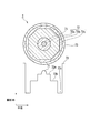
- FIG. 1 is a diagram showing a radial cross section and a refractive index distribution of a Yb-doped optical fiber 1.
- the Yb-doped optical fiber 1 is a single clad fiber, in which a clad 12 is provided on the outer periphery of the core 11 and a protective coating layer 13 is provided on the outer periphery of the clad 12.
- the fiber preform was produced by the MCVD method. Yb was added by a liquid immersion method. The fiber preform was spun until the glass outer diameter was about 125 ⁇ m, and a protective coating layer was provided on the outer periphery.
- FIG. 2 is a graph showing the relationship between the amount of loss before and after excitation light irradiation and the difference wavelength.
- FIG. 3 is a diagram showing a radial section and a refractive index distribution of the Yb-doped optical fiber 2.
- the Yb-doped optical fiber 2 is a single clad fiber, in which a clad 22 is provided on the outer periphery of the core 21 and a protective coating layer 23 is provided on the outer periphery of the clad 22.
- the fiber preform was produced by the VAD method. Yb was added by a liquid immersion method. The fiber preform was spun until the glass outer diameter was about 125 ⁇ m, and a protective coating layer was provided on the outer periphery.
- Yb 2 O 3 of the core is 0.38 mol%
- P 2 O 5 / Yb 2 O 3 is 29.71
- Al 2 O 3 / Yb 2 O 3 is 31.06
- Al 2 O 3 / P 2 O 5 was 1.05.
- the relative refractive index difference ( ⁇ ) of the core was 0.14%. Almost no increase in loss due to photodarkening was observed in the obtained Yb-doped optical fiber, and the loss increase by the evaluation method was 0.01 dB or less. Further, using the obtained Yb-doped optical fiber, a fiber laser was produced, and the temporal change in light output was evaluated. As a result, the decrease in output after 100 hours was 3% or less with a fiber laser having an initial output of 3 W.
- This output reduction amount includes not only an increase in optical fiber loss but also a cause due to temperature change and measurement variation. Therefore, it was considered that the output decrease due to the loss increase due to photodarkening was 1% or less.
- Table 1 shows the obtained Yb-doped optical fiber and the evaluation results.
- FIG. 4 is a diagram showing a radial section and a refractive index distribution of the Yb-doped optical fiber 3.
- the Yb-doped optical fiber 3 is a single clad fiber having a core 31 having a three-layer structure, in which a clad 32 is provided on the outer periphery of the core 31 and a protective coating layer 33 is provided on the outer periphery of the clad 32.
- the core 31 includes a center core 31a, a ring groove 31b provided on the outer periphery of the center core 31a, and a ring core 31c provided on the outer periphery of the ring groove 31b.
- the fiber preform was produced by the MCVD method.
- Yb was added by a liquid immersion method.
- the fiber preform was spun until the glass outer diameter was about 125 ⁇ m, and a protective coating layer was provided on the outer periphery.
- the core Yb 2 O 3 is 0.09 mol%, P 2 O 5 / Yb 2 O 3 is 22.33, Al 2 O 3 / Yb 2 O 3 is 28.00, Al 2 O 3 / P 2 O 5 Was 1.25.
- the relative refractive index difference ( ⁇ ) of the core was 0.07%.
- FIG. 5 is a diagram showing a radial section and a refractive index distribution of the Yb-doped optical fiber 4.
- the Yb-doped optical fiber 4 is a double-clad fiber having a clad 42 having a two-layer structure.
- An inner clad 42a is provided on the outer circumference of the core 41
- an outer clad 42b is provided on the outer circumference of the inner clad 42a
- the protective coating layer 43 is provided on the outer periphery of 42b.
- the cross-sectional shape of the inner cladding 42a is a D shape.
- the fiber preform was produced by the MCVD method. Yb was added by spraying droplets during soot production. At this point, the cylindrical fiber preform was cut off so that the cross-sectional shape was a D shape as shown in FIG. Then, the obtained fiber preform was spun until the diameter of the circumscribed circle of the glass became about 400 ⁇ m. At this time, a polymer clad material having a refractive index lower than that of the glass was applied and cured on the outer periphery of the glass so that excitation light was confined in the glass clad. Further, the outer periphery was coated with a protective UV curable resin.
- the core Yb 2 O 3 is 0.52 mol%, P 2 O 5 / Yb 2 O 3 is 3.04, Al 2 O 3 / Yb 2 O 3 is 3.10, Al 2 O 3 / P 2 O 5 was 1.02.
- the relative refractive index difference ( ⁇ ) of the core was 0.24%.
- the clad NA obtained from the difference in refractive index between the glass clad for guiding the excitation light and the polymer clad for confining the light was about 0.46. Almost no increase in loss due to photodarkening was observed in the obtained Yb-doped optical fiber, and the loss increase by the evaluation method was 0.01 dB or less.
- FIG. 6 is a diagram illustrating a radial section and a refractive index distribution of the Yb-doped optical fiber 5.
- the Yb-doped optical fiber 5 is a double-clad fiber having a clad 52 having a two-layer structure, and an inner cladding 52a is provided on the outer periphery of the core 51, an outer cladding 52b is provided on the outer periphery of the inner cladding 52a, and an outer cladding.
- a protective coating layer 53 is provided on the outer periphery of 52b.
- a pair of stress applying portions 54 and 54 are provided at positions symmetrical to the core 51.
- the fiber preform was produced by the VAD method.
- Yb was added by spraying droplets during soot production.
- a pair of holes are provided in the central axis direction of the fiber preform so as to be symmetrical with respect to the core, and stress-applied glass prepared by adding boron or the like is inserted therein, and the outer diameter of the glass is about 125 ⁇ m. Spinning until.
- a polymer clad material having a refractive index lower than that of the glass was applied and cured on the outer periphery of the glass so that excitation light was confined in the glass clad. Further, the outer periphery was coated with a protective UV curable resin.
- the core Yb 2 O 3 is 0.33 mol%, P 2 O 5 / Yb 2 O 3 is 3.02, Al 2 O 3 / Yb 2 O 3 is 5.34, Al 2 O 3 / P 2 O 5 was 1.76.
- the relative refractive index difference ( ⁇ ) of the core was 0.29%.
- the clad NA obtained from the difference in refractive index between the glass clad for guiding the excitation light and the polymer clad for confining the light was about 0.41. Almost no increase in loss due to photodarkening was observed in the obtained Yb-doped optical fiber, and the loss increase by the evaluation method was 0.01 dB or less.
- FIG. 7 is a diagram showing a radial section and a refractive index distribution of the Yb-doped optical fiber 6.
- the Yb-doped optical fiber 6 is a double-clad fiber having a clad 62 having a two-layer structure.
- An inner clad 62a is provided on the outer circumference of the core 61
- an outer clad 62b is provided on the outer circumference of the inner clad 62a
- a protective coating layer 63 is provided on the outer periphery of 62b.
- the cross-sectional shape of the inner cladding 62a is a regular heptagon, and the core 61, the inner cladding 62a, and the outer cladding 62b are arranged concentrically.
- the fiber preform was produced by the MCVD method. Yb was added by a liquid immersion method. At this point, the cylindrical fiber preform was cut off so that the cross-sectional shape was a regular heptagon as shown in FIG. The obtained fiber preform was spun until the diameter of the circumscribed circle of the glass became about 420 ⁇ m. At this time, a polymer clad material having a refractive index lower than that of the glass was applied and cured on the outer periphery of the glass so that excitation light was confined in the glass clad. Further, the outer periphery was coated with a protective UV curable resin.
- the core Yb 2 O 3 is 0.39 mol%, P 2 O 5 / Yb 2 O 3 is 11.98, Al 2 O 3 / Yb 2 O 3 is 18.34, Al 2 O 3 / P 2 O 5 was 1.53.
- the relative refractive index difference ( ⁇ ) of the core was 0.13%.
- the clad NA obtained from the difference in refractive index between the glass clad for guiding the excitation light and the polymer clad for confining the light was about 0.46. Almost no increase in loss due to photodarkening was observed in the obtained Yb-doped optical fiber, and the loss increase by the evaluation method was 0.01 dB or less.
- FIG. 8 is a diagram illustrating a radial section and a refractive index distribution of the Yb-doped optical fiber 7.
- the Yb-doped optical fiber 7 is a triple-clad fiber having a clad 72 having a three-layer structure, an innermost cladding 72a is provided on the outer periphery of the core 71, and an intermediate cladding 72b is provided on the outer periphery of the innermost cladding 72a.
- the outermost cladding 72c is provided on the outer periphery of the intermediate cladding 72b, and the protective coating layer 73 is provided on the outer periphery of the outermost cladding 72c.
- the cross section of the intermediate clad 72b is a regular octagon, and the core 71, the innermost clad 72a, the intermediate clad 72b, and the outermost clad 72c are arranged concentrically.
- the fiber preform was produced by the VAD method. Yb was added by a liquid immersion method. At this time, the cylindrical fiber preform was cut off so that the cross-sectional shape was a regular octagon as shown in FIG. The obtained fiber preform was spun until the diameter of the circumscribed circle of the glass cross section was about 380 ⁇ m. At this time, a polymer clad material having a refractive index lower than that of the glass was applied and cured on the outer periphery of the glass so that excitation light was confined in the glass clad. Further, the outer periphery was coated with a protective UV curable resin.
- Yb 2 O 3 of the core is 0.68 mol%, P 2 O 5 / Yb 2 O 3 is 17.79, Al 2 O 3 / Yb 2 O 3 is 18.87, Al 2 O 3 / P 2 O 5 Was 1.06.
- the relative refractive index difference ( ⁇ ) of the core was 0.28%.
- the clad NA obtained from the difference in refractive index between the glass clad for guiding the excitation light and the polymer clad for confining the light was about 0.47. Almost no increase in loss due to photodarkening was observed in the obtained Yb-doped optical fiber, and the loss increase by the evaluation method was 0.01 dB or less.
- FIG. 9 is a diagram showing a radial section and a refractive index distribution of the Yb-doped optical fiber 8.
- the Yb-doped optical fiber 8 is a triple clad fiber having a two-layer core 81 and a three-layer clad 82.
- the ring groove 81b is provided on the outer periphery of the center core 81a
- the innermost cladding 82a is provided on the outer periphery of the ring groove 81b
- the intermediate cladding 82b is provided on the outer periphery of the innermost cladding 82a
- the outer periphery of the intermediate cladding 82b is provided on the outer periphery of the intermediate cladding 82b.
- the outermost clad 82c is provided on the upper surface
- the protective coating layer 83 is provided on the outer periphery of the outermost clad 82c.
- the cross-sectional shape of the intermediate clad 82b is a regular heptagon, and the center core 81a, ring groove 81b, innermost clad 82a, intermediate clad 82b, and outermost clad 82c are arranged concentrically.
- the fiber preform was produced by the MCVD method.
- Yb was added by a liquid immersion method.
- the cylindrical fiber preform was cut off so that the cross-sectional shape was a regular heptagon as shown in FIG.
- the obtained fiber preform was spun until the diameter of the circumscribed circle of the glass became about 400 ⁇ m.
- a polymer clad material having a refractive index lower than that of the glass was applied and cured on the outer periphery of the glass so that excitation light was confined in the glass clad. Further, the outer periphery was coated with a protective UV curable resin.
- the core Yb 2 O 3 is 0.28 mol%, P 2 O 5 / Yb 2 O 3 is 5.79, Al 2 O 3 / Yb 2 O 3 is 7.61, Al 2 O 3 / P 2 O 5 1.31 and GeO 2 was 0.83 mol%.
- the relative refractive index difference ( ⁇ ) of the core was 0.27%.
- the clad NA obtained from the difference in refractive index between the glass clad for guiding the excitation light and the polymer clad for confining the light was about 0.46. Almost no increase in loss due to photodarkening was observed in the obtained Yb-doped optical fiber, and the loss increase by the evaluation method was 0.01 dB or less.
- FIG. 10 is a diagram showing a radial section and a refractive index distribution of the Yb-doped optical fiber 9.
- the Yb-doped optical fiber 9 is a double clad fiber having a clad 92 having a two-layer structure.
- An inner clad 92a is provided on the outer circumference of the core 91
- an outer clad 92b is provided on the outer circumference of the inner clad 92a
- the outer clad is provided on the outer periphery of 92b.
- a pair of stress applying portions 94 and 94 are provided at positions symmetrical to the core 91. Furthermore, the cross-sectional shape of the inner cladding 92a is a regular octagon, and the core 91, the inner cladding 92a, and the outer cladding 92b are arranged concentrically.
- the fiber preform was produced by the MCVD method.
- Yb was added by a liquid immersion method.
- the cylindrical fiber preform was cut off so that the cross-sectional shape was a regular octagon as shown in FIG.
- a pair of holes were provided in the direction of the central axis of the fiber preform so as to be symmetrical with respect to the core, and stress-applied glass produced by adding boron or the like was inserted therein.
- the obtained fiber preform was spun until the diameter of the circumscribed circle of the glass became about 250 ⁇ m.
- a polymer clad material having a refractive index lower than that of the glass was applied and cured on the outer periphery of the glass so that excitation light was confined in the glass clad. Further, the outer periphery was coated with a protective UV curable resin.
- Yb 2 O 3 of the core is 0.60 mol%
- P 2 O 5 / Yb 2 O 3 is 19.17
- Al 2 O 3 / Yb 2 O 3 is 20.17
- Al 2 O 3 / P 2 O 5 A polarization-maintaining optical fiber with 1.05 and F of 0.40 mol% was obtained.
- the relative refractive index difference ( ⁇ ) of the core was 0.18%.
- the clad NA obtained from the difference in refractive index between the glass clad for guiding the excitation light and the polymer clad for confining the light was about 0.43. Almost no increase in loss due to photodarkening was observed in the obtained Yb-doped optical fiber, and the loss increase by the evaluation method was 0.01 dB or less.
- FIG. 11 is a diagram illustrating a radial cross section and a refractive index distribution of the Yb-doped optical fiber 10.
- the Yb-doped optical fiber 10 is a double-clad fiber having a clad 102 having a two-layer structure.
- An inner clad 102a is provided on the outer circumference of the core 101
- an outer clad 102b is provided on the outer circumference of the inner clad 102a
- a protective coating layer 103 is provided on the outer periphery of 102b.
- the cross-sectional shape of the inner cladding 102a is a regular octagon, and the core 101, the inner cladding 102a, and the outer cladding 102b are arranged concentrically.
- the fiber preform was produced by the VAD method.
- Yb was added by a liquid immersion method.
- the cylindrical fiber preform was cut off so that the cross-sectional shape was a regular octagon as shown in FIG.
- the obtained fiber preform was spun until the diameter of the circumscribed circle of the glass became about 420 ⁇ m.
- a polymer clad material having a refractive index lower than that of the glass was applied and cured on the outer periphery of the glass so that excitation light was confined in the glass clad. Further, the outer periphery was coated with a protective UV curable resin.
- Yb 2 O 3 of the core is 0.26 mol%
- P 2 O 5 / Yb 2 O 3 is 6.62
- Al 2 O 3 / Yb 2 O 3 is 9.04
- GeO 2 was 0.92 mol%
- F was 0.35 mol%.
- the relative refractive index difference ( ⁇ ) of the core was 0.21%.
- the clad NA obtained from the difference in refractive index between the glass clad for guiding the excitation light and the polymer clad for confining the light was about 0.46. Almost no increase in loss due to photodarkening was observed in the obtained Yb-doped optical fiber, and the loss increase by the evaluation method was 0.01 dB or less.
- Example 11 The addition of B in addition to Al, P, and Yb to the core, the addition amount of Al, P, and Yb are different, and the fiber preform that has been cut off so that the cross-sectional shape is D-shaped
- a double clad fiber was prepared in the same manner as in Example 4 except that spinning was performed until the diameter reached about 125 ⁇ m.
- the core Yb 2 O 3 is 0.31 mol%
- P 2 O 5 / Yb 2 O 3 is 22.29
- Al 2 O 3 / Yb 2 O 3 is 25.23
- Al 2 O 3 / P 2 O 5 Was 1.13
- B 2 O 5 was 0.3 mol.
- the relative refractive index difference ( ⁇ ) of the core was 0.22%.
- the clad NA obtained from the difference in refractive index between the glass clad for guiding the excitation light and the polymer clad for confining the light was about 0.46. Almost no increase in loss due to photodarkening was observed in the obtained Yb-doped optical fiber, and the loss increase by the evaluation method was 0.01 dB or less. Further, using the obtained Yb-doped optical fiber, a fiber laser was produced, and the temporal change in light output was evaluated. As a result, the amount of decrease in output after 100 hours was 1% or less with a pulse fiber laser having an initial output of 20.0 W. This output reduction amount includes not only an increase in optical fiber loss but also a cause due to temperature change and measurement variation. For this reason, it was considered that there was almost no decrease in output due to increased loss due to photodarkening. Table 2 shows the obtained Yb-doped optical fibers and the evaluation results.
- Tm is added to the core in addition to Al, P, Yb, the addition amount of Al, P, Yb is different, and the fiber preform cut off so that the cross-sectional shape becomes a regular octagonal shape
- a triple clad fiber was produced in the same manner as in Example 7 except that spinning was performed until the diameter reached about 250 ⁇ m.
- Tm was added by an immersion method.
- Yb 2 O 3 of the core is 0.25 mol%
- P 2 O 5 / Yb 2 O 3 is 25.80
- Al 2 O 3 / Yb 2 O 3 is 27.52
- the relative refractive index difference ( ⁇ ) of the core was 0.25%.
- the clad NA obtained from the difference in refractive index between the glass clad for guiding the excitation light and the polymer clad for confining the light was about 0.46. Almost no increase in loss due to photodarkening was observed in the obtained Yb-doped optical fiber, and the loss increase by the evaluation method was 0.01 dB or less. Further, using the obtained Yb-doped optical fiber, a fiber laser was produced, and the temporal change in light output was evaluated. As a result, the output decrease after 100 hours was 3% or less with the pulse fiber laser having an initial output of 15 W.
- This output reduction amount includes not only an increase in optical fiber loss but also a cause due to temperature change and measurement variation. Therefore, it was considered that the output decrease due to the loss increase due to photodarkening was 1% or less.
- Table 2 shows the obtained Yb-doped optical fibers and the evaluation results.
- Example 13 Addition of Nd to the core in addition to Al, P, and Yb, different amounts of addition of Al, P, and Yb, and fiber preforms cut off so that the cross-sectional shape is a regular heptagonal shape.
- a triple clad fiber was produced in the same manner as in Example 8, except that spinning was performed until the diameter reached about 250 ⁇ m.
- Nd was added by the immersion method.
- Yb 2 O 3 of the core is 0.30 mol%
- P 2 O 5 / Yb 2 O 3 is 13.67
- Al 2 O 3 / Yb 2 O 3 is 16.53
- Al 2 O 3 / P 2 O 5 1.21 and Nd 2 O 3 were 0.15 mol.
- the relative refractive index difference ( ⁇ ) of the core was 0.18%.
- the clad NA obtained from the difference in refractive index between the glass clad for guiding the excitation light and the polymer clad for confining the light was about 0.43. Almost no increase in loss due to photodarkening was observed in the obtained Yb-doped optical fiber, and the loss increase by the evaluation method was 0.01 dB or less. Further, using the obtained Yb-doped optical fiber, a fiber laser was produced, and the temporal change in light output was evaluated. As a result, the output decrease after 100 hours was 1% or less with the pulsed fiber laser having an initial output of 15.8 W.
- This output reduction amount includes not only an increase in optical fiber loss but also a cause due to temperature change and measurement variation. Therefore, it was considered that the output decrease due to the loss increase due to photodarkening was 1% or less.
- Table 3 shows the obtained Yb-doped optical fibers and the evaluation results.
- Example 1 Example except that Al, Yb, Ge were added to the core, P was not added, the addition amount of Al, Yb was different, and the fiber preform was spun until the glass outer diameter was about 200 ⁇ m.
- a single clad fiber was produced.
- the core Yb 2 O 3 was 0.51 mol%
- Al 2 O 3 / Yb 2 O 3 was 0.39
- Al 2 O 3 was 0.2 mol%
- GeO 2 was 0.23 mol%. That is, Al 2 O 3 / Yb 2 O 3 was outside the scope of the present invention.
- the relative refractive index difference ( ⁇ ) of the core was 0.27%.
- the obtained Yb-doped optical fiber had a large loss increase due to photodarkening, and the loss increase amount by the evaluation method was 3.8 dB. Therefore, a fiber laser was produced using the obtained Yb-doped optical fiber, and the temporal change in the optical output was evaluated. As a result, the amount of decrease in output after 30 hours with a pulse fiber laser with an initial output of 20 W was 30% or more. Met. Table 3 shows the obtained Yb-doped optical fibers and the evaluation results.
- the relative refractive index difference ( ⁇ ) of the core was 0.20%.
- the clad NA obtained from the difference in refractive index between the glass clad for guiding the excitation light and the polymer clad for confining the light was about 0.43.
- the obtained Yb-doped optical fiber had a large loss increase due to photodarkening, and the loss increase amount by the evaluation method was 10.6 dB.
- FIG. 12 is a graph showing the relationship between the amount of loss before and after excitation light irradiation and the difference wavelength.
- the output decrease after 100 hours with a pulse fiber laser with an initial output of 12 W is 50% or more.
- Table 3 shows the obtained Yb-doped optical fibers and the evaluation results.
- a double clad fiber was produced in the same manner as in Example 2 except that the addition amounts of Al, P, and Yb were different, and that the polymer clad material was coated and cured to form a double clad structure.
- Yb 2 O 3 of the core is 0.45 mol%
- P 2 O 5 / Yb 2 O 3 is 30.7
- Al 2 O 3 / Yb 2 O 3 is 31.1
- Al 2 O 3 / P 2 O 5 Was 1.01. That is, P 2 O 5 / Yb 2 O 3 was outside the scope of the present invention.
- the relative refractive index difference ( ⁇ ) of the core was 0.27%.
- the clad NA obtained from the difference in refractive index between the glass clad for guiding the excitation light and the polymer clad for confining the light was about 0.46.
- the obtained Yb-doped optical fiber had a large transmission loss and reached about 160 dB / km. Therefore, using the obtained Yb-doped optical fiber, a fiber laser was fabricated and the optical output was evaluated. As a result, the initial output could be realized only up to 6W.
- Table 4 shows the obtained Yb-doped optical fiber and its evaluation results.
- a double clad fiber was prepared in the same manner as in Example 5 except that the addition amounts of Al, P, and Yb were different.
- the core Yb 2 O 3 is 0.22 mol%
- P 2 O 5 / Yb 2 O 3 is 2.14
- Al 2 O 3 / Yb 2 O 3 is 4.91
- Al 2 O 3 / P 2 O 5 was outside the scope of the present invention.
- the relative refractive index difference ( ⁇ ) of the core was 0.30%.
- the clad NA obtained from the refractive index difference between the glass clad for guiding the excitation light and the polymer clad for confining the light was about 0.44.
- the obtained Yb-doped optical fiber had a large loss increase due to photodarkening, and the loss increase amount by the evaluation method was 1.7 dB. Therefore, a fiber laser was manufactured using the obtained Yb-doped optical fiber, and the temporal change in the optical output was evaluated. As a result, the amount of output decrease after 100 hours with a pulsed fiber laser with an initial output of 12 W was 25% or more. Met. Table 4 shows the obtained Yb-doped optical fiber and its evaluation results.
- Example 6 A single clad fiber was produced in the same manner as in Example 2 except that the addition amounts of Al, P, and Yb were different.
- the core Yb 2 O 3 is 0.28 mol%
- P 2 O 5 / Yb 2 O 3 is 20.29
- Al 2 O 3 / Yb 2 O 3 is 38.57
- Al 2 O 3 / P 2 O 5 was 1.90. That is, Al 2 O 3 / Yb 2 O 3 was outside the scope of the present invention.
- the relative refractive index difference ( ⁇ ) of the core was 0.55%.
- the loss increase amount of the obtained Yb-doped optical fiber by the evaluation method was about 0.01 dB or less.
- the mode field diameter of the optical fiber was reduced because of the large relative refractive index difference ( ⁇ ). For this reason, stimulated Raman scattering occurs, and only a fiber laser with an initial output of 5 W can be realized. Further, as a result of producing a fiber laser using the obtained Yb-doped optical fiber and evaluating the temporal change of the optical output, the output decrease after 100 hours is 8% or more with a pulse fiber laser with an initial output of 5 W. Met. Table 4 shows the obtained Yb-doped optical fiber and its evaluation results.
- a double clad fiber was produced in the same manner as in Example 6 except that the addition amounts of Al, P, and Yb were different.
- the core Yb 2 O 3 is 0.48 mol%
- P 2 O 5 / Yb 2 O 3 is 9.02
- Al 2 O 3 / Yb 2 O 3 is 24.38
- Al 2 O 3 / P 2 O 5 was 2.70. That is, Al 2 O 3 / P 2 O 5 was outside the scope of the present invention.
- the relative refractive index difference ( ⁇ ) of the core was 0.85%.
- the clad NA obtained from the difference in refractive index between the glass clad for guiding the excitation light and the polymer clad for confining the light was about 0.46.
- the mode field diameter of the optical fiber was small due to the large relative refractive index difference ( ⁇ ). Therefore, stimulated Raman scattering occurs, and only a fiber laser with an initial output of 7 W can be realized.
- Table 4 shows the obtained Yb-doped optical fiber and its evaluation results.
- the present invention can be used as a laser medium for a high-power light source for material processing applications such as welding, marking, and cutting.
Abstract
L’invention concerne une fibre dopée à l’ytterbium comprenant une âme qui renferme au moins de l’ytterbium, de l’aluminium et du phosphore, et une gaine entourant l’âme. Dans l’âme, la teneur en ytterbium en termes d’oxyde d’ytterbium est comprise entre 0,09 et 0,68 % en moles ; le rapport molaire entre la teneur en phosphore en termes de pentoxyde de diphosphore et la teneur en ytterbium précitée en termes d’oxyde d’ytterbium est compris entre 3 et 30 ; le rapport molaire entre la teneur en oxyde d’aluminium précité en termes d’oxyde d’aluminium et la teneur en ytterbium précité en termes d’oxyde d’ytterbium est compris entre 3 et 32 ; et le rapport molaire entre la teneur en aluminium précité en termes d’oxyde d’aluminium et la teneur en pentoxyde de diphosphore est compris entre 1 et 2,5.
Priority Applications (7)
| Application Number | Priority Date | Filing Date | Title |
|---|---|---|---|
| CN200980112786.3A CN101999197B (zh) | 2008-11-14 | 2009-11-16 | 掺镱光纤、光纤激光器及光纤放大器 |
| EP09825949.2A EP2352209B1 (fr) | 2008-11-14 | 2009-11-16 | Fibre optique dopée à l'ytterbium, laser à fibre et amplificateur à fibres |
| DK09825949.2T DK2352209T3 (en) | 2008-11-14 | 2009-11-16 | OUTERBUM-DOTATED OPTICAL FIBER, FIBER LASER, AND FIBER AMPLIFIER |
| CA2721326A CA2721326C (fr) | 2008-11-14 | 2009-11-16 | Fibre optique dopee a l'ytterbium, laser a fibre et amplificateur a fibres |
| PCT/JP2009/006136 WO2010055696A1 (fr) | 2008-11-14 | 2009-11-16 | Fibre optique dopée à l’ytterbium, laser à fibre et amplificateur à fibres |
| JP2010522121A JP5436426B2 (ja) | 2008-11-14 | 2009-11-16 | イッテルビウム添加光ファイバ、ファイバレーザ及びファイバアンプ |
| US12/907,622 US8363313B2 (en) | 2008-11-14 | 2010-10-19 | Ytterbium-doped optical fiber, fiber laser, and fiber amplifier |
Applications Claiming Priority (2)
| Application Number | Priority Date | Filing Date | Title |
|---|---|---|---|
| JP2008-292013 | 2008-11-14 | ||
| JP2008292013 | 2008-11-14 |
Publications (1)
| Publication Number | Publication Date |
|---|---|
| WO2010055700A1 true WO2010055700A1 (fr) | 2010-05-20 |
Family
ID=42169843
Family Applications (1)
| Application Number | Title | Priority Date | Filing Date |
|---|---|---|---|
| PCT/JP2009/052756 WO2010055700A1 (fr) | 2008-11-14 | 2009-02-18 | Fibre optique dopée à l’ytterbium, laser à fibre et amplificateur à fibres |
Country Status (7)
| Country | Link |
|---|---|
| US (1) | US8363313B2 (fr) |
| EP (1) | EP2352209B1 (fr) |
| JP (1) | JP5436426B2 (fr) |
| CN (1) | CN101999197B (fr) |
| CA (1) | CA2721326C (fr) |
| DK (1) | DK2352209T3 (fr) |
| WO (1) | WO2010055700A1 (fr) |
Cited By (4)
| Publication number | Priority date | Publication date | Assignee | Title |
|---|---|---|---|---|
| CN102135641A (zh) * | 2011-03-29 | 2011-07-27 | 华中科技大学 | 一种抗光子暗化的有源光纤及其制备方法 |
| US8363313B2 (en) | 2008-11-14 | 2013-01-29 | Fujikura Ltd. | Ytterbium-doped optical fiber, fiber laser, and fiber amplifier |
| JP2016051804A (ja) * | 2014-08-29 | 2016-04-11 | 株式会社フジクラ | 増幅用偏波保持ファイバ、及び、それを用いたファイバレーザ装置 |
| CN108761635A (zh) * | 2018-05-03 | 2018-11-06 | 烽火通信科技股份有限公司 | 一种双包层掺镱光纤 |
Families Citing this family (173)
| Publication number | Priority date | Publication date | Assignee | Title |
|---|---|---|---|---|
| FR2952243B1 (fr) * | 2009-11-03 | 2012-05-11 | Univ Bordeaux 1 | Source optique mettant en oeuvre une fibre dopee, fibre pour une telle source optique et procede de fabrication d'une telle fibre |
| US8588568B2 (en) * | 2011-11-04 | 2013-11-19 | Corning Incorporated | Bend loss resistant multi-mode fiber |
| US8737778B2 (en) * | 2011-12-23 | 2014-05-27 | Jds Uniphase Corporation | Small form factor variable optical attenuator with cladding mode suppressing fiber |
| US10009065B2 (en) | 2012-12-05 | 2018-06-26 | At&T Intellectual Property I, L.P. | Backhaul link for distributed antenna system |
| US9113347B2 (en) | 2012-12-05 | 2015-08-18 | At&T Intellectual Property I, Lp | Backhaul link for distributed antenna system |
| US9525524B2 (en) | 2013-05-31 | 2016-12-20 | At&T Intellectual Property I, L.P. | Remote distributed antenna system |
| US9999038B2 (en) | 2013-05-31 | 2018-06-12 | At&T Intellectual Property I, L.P. | Remote distributed antenna system |
| US8897697B1 (en) | 2013-11-06 | 2014-11-25 | At&T Intellectual Property I, Lp | Millimeter-wave surface-wave communications |
| US9209902B2 (en) | 2013-12-10 | 2015-12-08 | At&T Intellectual Property I, L.P. | Quasi-optical coupler |
| JP5946196B2 (ja) * | 2014-04-01 | 2016-07-05 | 日本電信電話株式会社 | ファイバおよびファイバ増幅器 |
| US9692101B2 (en) | 2014-08-26 | 2017-06-27 | At&T Intellectual Property I, L.P. | Guided wave couplers for coupling electromagnetic waves between a waveguide surface and a surface of a wire |
| US9768833B2 (en) | 2014-09-15 | 2017-09-19 | At&T Intellectual Property I, L.P. | Method and apparatus for sensing a condition in a transmission medium of electromagnetic waves |
| US10063280B2 (en) | 2014-09-17 | 2018-08-28 | At&T Intellectual Property I, L.P. | Monitoring and mitigating conditions in a communication network |
| US9628854B2 (en) | 2014-09-29 | 2017-04-18 | At&T Intellectual Property I, L.P. | Method and apparatus for distributing content in a communication network |
| US9615269B2 (en) | 2014-10-02 | 2017-04-04 | At&T Intellectual Property I, L.P. | Method and apparatus that provides fault tolerance in a communication network |
| US9685992B2 (en) | 2014-10-03 | 2017-06-20 | At&T Intellectual Property I, L.P. | Circuit panel network and methods thereof |
| US9503189B2 (en) | 2014-10-10 | 2016-11-22 | At&T Intellectual Property I, L.P. | Method and apparatus for arranging communication sessions in a communication system |
| US9973299B2 (en) | 2014-10-14 | 2018-05-15 | At&T Intellectual Property I, L.P. | Method and apparatus for adjusting a mode of communication in a communication network |
| US9762289B2 (en) | 2014-10-14 | 2017-09-12 | At&T Intellectual Property I, L.P. | Method and apparatus for transmitting or receiving signals in a transportation system |
| US9653770B2 (en) | 2014-10-21 | 2017-05-16 | At&T Intellectual Property I, L.P. | Guided wave coupler, coupling module and methods for use therewith |
| US9312919B1 (en) | 2014-10-21 | 2016-04-12 | At&T Intellectual Property I, Lp | Transmission device with impairment compensation and methods for use therewith |
| US9577306B2 (en) | 2014-10-21 | 2017-02-21 | At&T Intellectual Property I, L.P. | Guided-wave transmission device and methods for use therewith |
| US9769020B2 (en) | 2014-10-21 | 2017-09-19 | At&T Intellectual Property I, L.P. | Method and apparatus for responding to events affecting communications in a communication network |
| US9780834B2 (en) | 2014-10-21 | 2017-10-03 | At&T Intellectual Property I, L.P. | Method and apparatus for transmitting electromagnetic waves |
| US9564947B2 (en) | 2014-10-21 | 2017-02-07 | At&T Intellectual Property I, L.P. | Guided-wave transmission device with diversity and methods for use therewith |
| US9520945B2 (en) | 2014-10-21 | 2016-12-13 | At&T Intellectual Property I, L.P. | Apparatus for providing communication services and methods thereof |
| US9627768B2 (en) | 2014-10-21 | 2017-04-18 | At&T Intellectual Property I, L.P. | Guided-wave transmission device with non-fundamental mode propagation and methods for use therewith |
| US9461706B1 (en) | 2015-07-31 | 2016-10-04 | At&T Intellectual Property I, Lp | Method and apparatus for exchanging communication signals |
| US9680670B2 (en) | 2014-11-20 | 2017-06-13 | At&T Intellectual Property I, L.P. | Transmission device with channel equalization and control and methods for use therewith |
| US9742462B2 (en) | 2014-12-04 | 2017-08-22 | At&T Intellectual Property I, L.P. | Transmission medium and communication interfaces and methods for use therewith |
| US9954287B2 (en) | 2014-11-20 | 2018-04-24 | At&T Intellectual Property I, L.P. | Apparatus for converting wireless signals and electromagnetic waves and methods thereof |
| US9800327B2 (en) | 2014-11-20 | 2017-10-24 | At&T Intellectual Property I, L.P. | Apparatus for controlling operations of a communication device and methods thereof |
| US9654173B2 (en) | 2014-11-20 | 2017-05-16 | At&T Intellectual Property I, L.P. | Apparatus for powering a communication device and methods thereof |
| US10340573B2 (en) | 2016-10-26 | 2019-07-02 | At&T Intellectual Property I, L.P. | Launcher with cylindrical coupling device and methods for use therewith |
| US10243784B2 (en) | 2014-11-20 | 2019-03-26 | At&T Intellectual Property I, L.P. | System for generating topology information and methods thereof |
| US9544006B2 (en) | 2014-11-20 | 2017-01-10 | At&T Intellectual Property I, L.P. | Transmission device with mode division multiplexing and methods for use therewith |
| US9997819B2 (en) | 2015-06-09 | 2018-06-12 | At&T Intellectual Property I, L.P. | Transmission medium and method for facilitating propagation of electromagnetic waves via a core |
| US10009067B2 (en) | 2014-12-04 | 2018-06-26 | At&T Intellectual Property I, L.P. | Method and apparatus for configuring a communication interface |
| US10144036B2 (en) | 2015-01-30 | 2018-12-04 | At&T Intellectual Property I, L.P. | Method and apparatus for mitigating interference affecting a propagation of electromagnetic waves guided by a transmission medium |
| US9876570B2 (en) | 2015-02-20 | 2018-01-23 | At&T Intellectual Property I, Lp | Guided-wave transmission device with non-fundamental mode propagation and methods for use therewith |
| US9749013B2 (en) | 2015-03-17 | 2017-08-29 | At&T Intellectual Property I, L.P. | Method and apparatus for reducing attenuation of electromagnetic waves guided by a transmission medium |
| US9705561B2 (en) | 2015-04-24 | 2017-07-11 | At&T Intellectual Property I, L.P. | Directional coupling device and methods for use therewith |
| US10224981B2 (en) | 2015-04-24 | 2019-03-05 | At&T Intellectual Property I, Lp | Passive electrical coupling device and methods for use therewith |
| US9948354B2 (en) | 2015-04-28 | 2018-04-17 | At&T Intellectual Property I, L.P. | Magnetic coupling device with reflective plate and methods for use therewith |
| US9793954B2 (en) | 2015-04-28 | 2017-10-17 | At&T Intellectual Property I, L.P. | Magnetic coupling device and methods for use therewith |
| US9871282B2 (en) | 2015-05-14 | 2018-01-16 | At&T Intellectual Property I, L.P. | At least one transmission medium having a dielectric surface that is covered at least in part by a second dielectric |
| US9748626B2 (en) | 2015-05-14 | 2017-08-29 | At&T Intellectual Property I, L.P. | Plurality of cables having different cross-sectional shapes which are bundled together to form a transmission medium |
| US9490869B1 (en) | 2015-05-14 | 2016-11-08 | At&T Intellectual Property I, L.P. | Transmission medium having multiple cores and methods for use therewith |
| US10679767B2 (en) | 2015-05-15 | 2020-06-09 | At&T Intellectual Property I, L.P. | Transmission medium having a conductive material and methods for use therewith |
| US10650940B2 (en) | 2015-05-15 | 2020-05-12 | At&T Intellectual Property I, L.P. | Transmission medium having a conductive material and methods for use therewith |
| US9917341B2 (en) | 2015-05-27 | 2018-03-13 | At&T Intellectual Property I, L.P. | Apparatus and method for launching electromagnetic waves and for modifying radial dimensions of the propagating electromagnetic waves |
| US10348391B2 (en) | 2015-06-03 | 2019-07-09 | At&T Intellectual Property I, L.P. | Client node device with frequency conversion and methods for use therewith |
| US10103801B2 (en) | 2015-06-03 | 2018-10-16 | At&T Intellectual Property I, L.P. | Host node device and methods for use therewith |
| US9866309B2 (en) | 2015-06-03 | 2018-01-09 | At&T Intellectual Property I, Lp | Host node device and methods for use therewith |
| US9912381B2 (en) | 2015-06-03 | 2018-03-06 | At&T Intellectual Property I, Lp | Network termination and methods for use therewith |
| US10154493B2 (en) | 2015-06-03 | 2018-12-11 | At&T Intellectual Property I, L.P. | Network termination and methods for use therewith |
| US10812174B2 (en) | 2015-06-03 | 2020-10-20 | At&T Intellectual Property I, L.P. | Client node device and methods for use therewith |
| US9913139B2 (en) | 2015-06-09 | 2018-03-06 | At&T Intellectual Property I, L.P. | Signal fingerprinting for authentication of communicating devices |
| US10142086B2 (en) | 2015-06-11 | 2018-11-27 | At&T Intellectual Property I, L.P. | Repeater and methods for use therewith |
| US9608692B2 (en) | 2015-06-11 | 2017-03-28 | At&T Intellectual Property I, L.P. | Repeater and methods for use therewith |
| US9820146B2 (en) | 2015-06-12 | 2017-11-14 | At&T Intellectual Property I, L.P. | Method and apparatus for authentication and identity management of communicating devices |
| US9667317B2 (en) | 2015-06-15 | 2017-05-30 | At&T Intellectual Property I, L.P. | Method and apparatus for providing security using network traffic adjustments |
| US9865911B2 (en) | 2015-06-25 | 2018-01-09 | At&T Intellectual Property I, L.P. | Waveguide system for slot radiating first electromagnetic waves that are combined into a non-fundamental wave mode second electromagnetic wave on a transmission medium |
| US9640850B2 (en) | 2015-06-25 | 2017-05-02 | At&T Intellectual Property I, L.P. | Methods and apparatus for inducing a non-fundamental wave mode on a transmission medium |
| US9509415B1 (en) | 2015-06-25 | 2016-11-29 | At&T Intellectual Property I, L.P. | Methods and apparatus for inducing a fundamental wave mode on a transmission medium |
| US10341142B2 (en) | 2015-07-14 | 2019-07-02 | At&T Intellectual Property I, L.P. | Apparatus and methods for generating non-interfering electromagnetic waves on an uninsulated conductor |
| US9853342B2 (en) | 2015-07-14 | 2017-12-26 | At&T Intellectual Property I, L.P. | Dielectric transmission medium connector and methods for use therewith |
| US9847566B2 (en) | 2015-07-14 | 2017-12-19 | At&T Intellectual Property I, L.P. | Method and apparatus for adjusting a field of a signal to mitigate interference |
| US10148016B2 (en) | 2015-07-14 | 2018-12-04 | At&T Intellectual Property I, L.P. | Apparatus and methods for communicating utilizing an antenna array |
| US9882257B2 (en) | 2015-07-14 | 2018-01-30 | At&T Intellectual Property I, L.P. | Method and apparatus for launching a wave mode that mitigates interference |
| US10033108B2 (en) | 2015-07-14 | 2018-07-24 | At&T Intellectual Property I, L.P. | Apparatus and methods for generating an electromagnetic wave having a wave mode that mitigates interference |
| US10170840B2 (en) | 2015-07-14 | 2019-01-01 | At&T Intellectual Property I, L.P. | Apparatus and methods for sending or receiving electromagnetic signals |
| US9722318B2 (en) | 2015-07-14 | 2017-08-01 | At&T Intellectual Property I, L.P. | Method and apparatus for coupling an antenna to a device |
| US9836957B2 (en) | 2015-07-14 | 2017-12-05 | At&T Intellectual Property I, L.P. | Method and apparatus for communicating with premises equipment |
| US10205655B2 (en) | 2015-07-14 | 2019-02-12 | At&T Intellectual Property I, L.P. | Apparatus and methods for communicating utilizing an antenna array and multiple communication paths |
| US9628116B2 (en) | 2015-07-14 | 2017-04-18 | At&T Intellectual Property I, L.P. | Apparatus and methods for transmitting wireless signals |
| US10320586B2 (en) | 2015-07-14 | 2019-06-11 | At&T Intellectual Property I, L.P. | Apparatus and methods for generating non-interfering electromagnetic waves on an insulated transmission medium |
| US10044409B2 (en) | 2015-07-14 | 2018-08-07 | At&T Intellectual Property I, L.P. | Transmission medium and methods for use therewith |
| US10033107B2 (en) | 2015-07-14 | 2018-07-24 | At&T Intellectual Property I, L.P. | Method and apparatus for coupling an antenna to a device |
| US9793951B2 (en) | 2015-07-15 | 2017-10-17 | At&T Intellectual Property I, L.P. | Method and apparatus for launching a wave mode that mitigates interference |
| US9608740B2 (en) | 2015-07-15 | 2017-03-28 | At&T Intellectual Property I, L.P. | Method and apparatus for launching a wave mode that mitigates interference |
| US10090606B2 (en) | 2015-07-15 | 2018-10-02 | At&T Intellectual Property I, L.P. | Antenna system with dielectric array and methods for use therewith |
| CN104932054B (zh) * | 2015-07-20 | 2018-02-23 | 富通集团有限公司 | 一种三包层掺铥光纤及其制备方法 |
| US9912027B2 (en) | 2015-07-23 | 2018-03-06 | At&T Intellectual Property I, L.P. | Method and apparatus for exchanging communication signals |
| US10784670B2 (en) | 2015-07-23 | 2020-09-22 | At&T Intellectual Property I, L.P. | Antenna support for aligning an antenna |
| US9871283B2 (en) | 2015-07-23 | 2018-01-16 | At&T Intellectual Property I, Lp | Transmission medium having a dielectric core comprised of plural members connected by a ball and socket configuration |
| US9749053B2 (en) | 2015-07-23 | 2017-08-29 | At&T Intellectual Property I, L.P. | Node device, repeater and methods for use therewith |
| US9948333B2 (en) | 2015-07-23 | 2018-04-17 | At&T Intellectual Property I, L.P. | Method and apparatus for wireless communications to mitigate interference |
| US10020587B2 (en) | 2015-07-31 | 2018-07-10 | At&T Intellectual Property I, L.P. | Radial antenna and methods for use therewith |
| US9967173B2 (en) | 2015-07-31 | 2018-05-08 | At&T Intellectual Property I, L.P. | Method and apparatus for authentication and identity management of communicating devices |
| US9735833B2 (en) | 2015-07-31 | 2017-08-15 | At&T Intellectual Property I, L.P. | Method and apparatus for communications management in a neighborhood network |
| US9904535B2 (en) | 2015-09-14 | 2018-02-27 | At&T Intellectual Property I, L.P. | Method and apparatus for distributing software |
| US10136434B2 (en) | 2015-09-16 | 2018-11-20 | At&T Intellectual Property I, L.P. | Method and apparatus for use with a radio distributed antenna system having an ultra-wideband control channel |
| US10079661B2 (en) | 2015-09-16 | 2018-09-18 | At&T Intellectual Property I, L.P. | Method and apparatus for use with a radio distributed antenna system having a clock reference |
| US10009063B2 (en) | 2015-09-16 | 2018-06-26 | At&T Intellectual Property I, L.P. | Method and apparatus for use with a radio distributed antenna system having an out-of-band reference signal |
| US10009901B2 (en) | 2015-09-16 | 2018-06-26 | At&T Intellectual Property I, L.P. | Method, apparatus, and computer-readable storage medium for managing utilization of wireless resources between base stations |
| US9705571B2 (en) | 2015-09-16 | 2017-07-11 | At&T Intellectual Property I, L.P. | Method and apparatus for use with a radio distributed antenna system |
| US10051629B2 (en) | 2015-09-16 | 2018-08-14 | At&T Intellectual Property I, L.P. | Method and apparatus for use with a radio distributed antenna system having an in-band reference signal |
| US9769128B2 (en) | 2015-09-28 | 2017-09-19 | At&T Intellectual Property I, L.P. | Method and apparatus for encryption of communications over a network |
| US9729197B2 (en) | 2015-10-01 | 2017-08-08 | At&T Intellectual Property I, L.P. | Method and apparatus for communicating network management traffic over a network |
| US9882277B2 (en) | 2015-10-02 | 2018-01-30 | At&T Intellectual Property I, Lp | Communication device and antenna assembly with actuated gimbal mount |
| US10074890B2 (en) | 2015-10-02 | 2018-09-11 | At&T Intellectual Property I, L.P. | Communication device and antenna with integrated light assembly |
| US9876264B2 (en) | 2015-10-02 | 2018-01-23 | At&T Intellectual Property I, Lp | Communication system, guided wave switch and methods for use therewith |
| US10665942B2 (en) | 2015-10-16 | 2020-05-26 | At&T Intellectual Property I, L.P. | Method and apparatus for adjusting wireless communications |
| US10355367B2 (en) | 2015-10-16 | 2019-07-16 | At&T Intellectual Property I, L.P. | Antenna structure for exchanging wireless signals |
| US10051483B2 (en) | 2015-10-16 | 2018-08-14 | At&T Intellectual Property I, L.P. | Method and apparatus for directing wireless signals |
| US9912419B1 (en) | 2016-08-24 | 2018-03-06 | At&T Intellectual Property I, L.P. | Method and apparatus for managing a fault in a distributed antenna system |
| US9860075B1 (en) | 2016-08-26 | 2018-01-02 | At&T Intellectual Property I, L.P. | Method and communication node for broadband distribution |
| US10291311B2 (en) | 2016-09-09 | 2019-05-14 | At&T Intellectual Property I, L.P. | Method and apparatus for mitigating a fault in a distributed antenna system |
| US11032819B2 (en) | 2016-09-15 | 2021-06-08 | At&T Intellectual Property I, L.P. | Method and apparatus for use with a radio distributed antenna system having a control channel reference signal |
| US10135146B2 (en) | 2016-10-18 | 2018-11-20 | At&T Intellectual Property I, L.P. | Apparatus and methods for launching guided waves via circuits |
| US10340600B2 (en) | 2016-10-18 | 2019-07-02 | At&T Intellectual Property I, L.P. | Apparatus and methods for launching guided waves via plural waveguide systems |
| US10135147B2 (en) | 2016-10-18 | 2018-11-20 | At&T Intellectual Property I, L.P. | Apparatus and methods for launching guided waves via an antenna |
| US9991580B2 (en) | 2016-10-21 | 2018-06-05 | At&T Intellectual Property I, L.P. | Launcher and coupling system for guided wave mode cancellation |
| US9876605B1 (en) | 2016-10-21 | 2018-01-23 | At&T Intellectual Property I, L.P. | Launcher and coupling system to support desired guided wave mode |
| US10374316B2 (en) | 2016-10-21 | 2019-08-06 | At&T Intellectual Property I, L.P. | System and dielectric antenna with non-uniform dielectric |
| US10811767B2 (en) | 2016-10-21 | 2020-10-20 | At&T Intellectual Property I, L.P. | System and dielectric antenna with convex dielectric radome |
| US10312567B2 (en) | 2016-10-26 | 2019-06-04 | At&T Intellectual Property I, L.P. | Launcher with planar strip antenna and methods for use therewith |
| US10225025B2 (en) | 2016-11-03 | 2019-03-05 | At&T Intellectual Property I, L.P. | Method and apparatus for detecting a fault in a communication system |
| US10224634B2 (en) | 2016-11-03 | 2019-03-05 | At&T Intellectual Property I, L.P. | Methods and apparatus for adjusting an operational characteristic of an antenna |
| US10291334B2 (en) | 2016-11-03 | 2019-05-14 | At&T Intellectual Property I, L.P. | System for detecting a fault in a communication system |
| US10498044B2 (en) | 2016-11-03 | 2019-12-03 | At&T Intellectual Property I, L.P. | Apparatus for configuring a surface of an antenna |
| US10535928B2 (en) | 2016-11-23 | 2020-01-14 | At&T Intellectual Property I, L.P. | Antenna system and methods for use therewith |
| US10090594B2 (en) | 2016-11-23 | 2018-10-02 | At&T Intellectual Property I, L.P. | Antenna system having structural configurations for assembly |
| US10340603B2 (en) | 2016-11-23 | 2019-07-02 | At&T Intellectual Property I, L.P. | Antenna system having shielded structural configurations for assembly |
| US10340601B2 (en) | 2016-11-23 | 2019-07-02 | At&T Intellectual Property I, L.P. | Multi-antenna system and methods for use therewith |
| US10178445B2 (en) | 2016-11-23 | 2019-01-08 | At&T Intellectual Property I, L.P. | Methods, devices, and systems for load balancing between a plurality of waveguides |
| US10305190B2 (en) | 2016-12-01 | 2019-05-28 | At&T Intellectual Property I, L.P. | Reflecting dielectric antenna system and methods for use therewith |
| US10361489B2 (en) | 2016-12-01 | 2019-07-23 | At&T Intellectual Property I, L.P. | Dielectric dish antenna system and methods for use therewith |
| US10439675B2 (en) | 2016-12-06 | 2019-10-08 | At&T Intellectual Property I, L.P. | Method and apparatus for repeating guided wave communication signals |
| US10694379B2 (en) | 2016-12-06 | 2020-06-23 | At&T Intellectual Property I, L.P. | Waveguide system with device-based authentication and methods for use therewith |
| US10020844B2 (en) | 2016-12-06 | 2018-07-10 | T&T Intellectual Property I, L.P. | Method and apparatus for broadcast communication via guided waves |
| US10727599B2 (en) | 2016-12-06 | 2020-07-28 | At&T Intellectual Property I, L.P. | Launcher with slot antenna and methods for use therewith |
| US10382976B2 (en) | 2016-12-06 | 2019-08-13 | At&T Intellectual Property I, L.P. | Method and apparatus for managing wireless communications based on communication paths and network device positions |
| US10755542B2 (en) | 2016-12-06 | 2020-08-25 | At&T Intellectual Property I, L.P. | Method and apparatus for surveillance via guided wave communication |
| US10819035B2 (en) | 2016-12-06 | 2020-10-27 | At&T Intellectual Property I, L.P. | Launcher with helical antenna and methods for use therewith |
| US9927517B1 (en) | 2016-12-06 | 2018-03-27 | At&T Intellectual Property I, L.P. | Apparatus and methods for sensing rainfall |
| US10135145B2 (en) | 2016-12-06 | 2018-11-20 | At&T Intellectual Property I, L.P. | Apparatus and methods for generating an electromagnetic wave along a transmission medium |
| US10326494B2 (en) | 2016-12-06 | 2019-06-18 | At&T Intellectual Property I, L.P. | Apparatus for measurement de-embedding and methods for use therewith |
| US10637149B2 (en) | 2016-12-06 | 2020-04-28 | At&T Intellectual Property I, L.P. | Injection molded dielectric antenna and methods for use therewith |
| US10446936B2 (en) | 2016-12-07 | 2019-10-15 | At&T Intellectual Property I, L.P. | Multi-feed dielectric antenna system and methods for use therewith |
| US10243270B2 (en) | 2016-12-07 | 2019-03-26 | At&T Intellectual Property I, L.P. | Beam adaptive multi-feed dielectric antenna system and methods for use therewith |
| US10027397B2 (en) | 2016-12-07 | 2018-07-17 | At&T Intellectual Property I, L.P. | Distributed antenna system and methods for use therewith |
| US9893795B1 (en) | 2016-12-07 | 2018-02-13 | At&T Intellectual Property I, Lp | Method and repeater for broadband distribution |
| US10359749B2 (en) | 2016-12-07 | 2019-07-23 | At&T Intellectual Property I, L.P. | Method and apparatus for utilities management via guided wave communication |
| US10139820B2 (en) | 2016-12-07 | 2018-11-27 | At&T Intellectual Property I, L.P. | Method and apparatus for deploying equipment of a communication system |
| US10168695B2 (en) | 2016-12-07 | 2019-01-01 | At&T Intellectual Property I, L.P. | Method and apparatus for controlling an unmanned aircraft |
| US10547348B2 (en) | 2016-12-07 | 2020-01-28 | At&T Intellectual Property I, L.P. | Method and apparatus for switching transmission mediums in a communication system |
| US10389029B2 (en) | 2016-12-07 | 2019-08-20 | At&T Intellectual Property I, L.P. | Multi-feed dielectric antenna system with core selection and methods for use therewith |
| US10938108B2 (en) | 2016-12-08 | 2021-03-02 | At&T Intellectual Property I, L.P. | Frequency selective multi-feed dielectric antenna system and methods for use therewith |
| US10411356B2 (en) | 2016-12-08 | 2019-09-10 | At&T Intellectual Property I, L.P. | Apparatus and methods for selectively targeting communication devices with an antenna array |
| US10530505B2 (en) | 2016-12-08 | 2020-01-07 | At&T Intellectual Property I, L.P. | Apparatus and methods for launching electromagnetic waves along a transmission medium |
| US10326689B2 (en) | 2016-12-08 | 2019-06-18 | At&T Intellectual Property I, L.P. | Method and system for providing alternative communication paths |
| US10601494B2 (en) | 2016-12-08 | 2020-03-24 | At&T Intellectual Property I, L.P. | Dual-band communication device and method for use therewith |
| US9911020B1 (en) | 2016-12-08 | 2018-03-06 | At&T Intellectual Property I, L.P. | Method and apparatus for tracking via a radio frequency identification device |
| US10389037B2 (en) | 2016-12-08 | 2019-08-20 | At&T Intellectual Property I, L.P. | Apparatus and methods for selecting sections of an antenna array and use therewith |
| US10777873B2 (en) | 2016-12-08 | 2020-09-15 | At&T Intellectual Property I, L.P. | Method and apparatus for mounting network devices |
| US10103422B2 (en) | 2016-12-08 | 2018-10-16 | At&T Intellectual Property I, L.P. | Method and apparatus for mounting network devices |
| US10916969B2 (en) | 2016-12-08 | 2021-02-09 | At&T Intellectual Property I, L.P. | Method and apparatus for providing power using an inductive coupling |
| US9998870B1 (en) | 2016-12-08 | 2018-06-12 | At&T Intellectual Property I, L.P. | Method and apparatus for proximity sensing |
| US10069535B2 (en) | 2016-12-08 | 2018-09-04 | At&T Intellectual Property I, L.P. | Apparatus and methods for launching electromagnetic waves having a certain electric field structure |
| US10264586B2 (en) | 2016-12-09 | 2019-04-16 | At&T Mobility Ii Llc | Cloud-based packet controller and methods for use therewith |
| US9838896B1 (en) | 2016-12-09 | 2017-12-05 | At&T Intellectual Property I, L.P. | Method and apparatus for assessing network coverage |
| US10340983B2 (en) | 2016-12-09 | 2019-07-02 | At&T Intellectual Property I, L.P. | Method and apparatus for surveying remote sites via guided wave communications |
| US9973940B1 (en) | 2017-02-27 | 2018-05-15 | At&T Intellectual Property I, L.P. | Apparatus and methods for dynamic impedance matching of a guided wave launcher |
| US10298293B2 (en) | 2017-03-13 | 2019-05-21 | At&T Intellectual Property I, L.P. | Apparatus of communication utilizing wireless network devices |
| CN110323659A (zh) | 2018-03-30 | 2019-10-11 | 株式会社藤仓 | 放大用光纤、光纤激光装置以及光谐振器 |
| JP7360270B2 (ja) | 2018-09-18 | 2023-10-12 | 株式会社フジクラ | 光ファイバの製造方法及び光ファイバの製造装置 |
| KR102337546B1 (ko) * | 2019-11-01 | 2021-12-09 | 레이저닉스 주식회사 | 계단형 넓은 모드 면적 광섬유를 이용한 광증폭기 및 이를 포함하는 극초단 펄스 광섬유 레이저 장치 |
| EP3869636B1 (fr) * | 2020-02-21 | 2024-03-13 | Toyota Jidosha Kabushiki Kaisha | Fibre d'amplification et appareil d'émission de faisceau laser |
| CN111443423B (zh) * | 2020-03-12 | 2022-03-11 | 烽火通信科技股份有限公司 | 一种耐辐照保偏光纤及其制备方法和应用 |
| WO2024020682A1 (fr) * | 2022-07-26 | 2024-02-01 | Raman Kashyap | Procédé de fabrication d'un matériau dopé et dispositif photonique associé |
| CN116282882B (zh) * | 2023-03-05 | 2024-04-19 | 北京工业大学 | 一种Nd3+掺杂石英光纤预制棒及制备方法 |
Citations (6)
| Publication number | Priority date | Publication date | Assignee | Title |
|---|---|---|---|---|
| JPH01298043A (ja) * | 1988-02-08 | 1989-12-01 | American Teleph & Telegr Co <Att> | アルミニウムおよびリン含有シリカ系ガラスを含む物品 |
| JPH09194225A (ja) * | 1995-11-22 | 1997-07-29 | Lucent Technol Inc | クラッディングポンプファイバとその製造方法 |
| JPH11112070A (ja) * | 1997-08-07 | 1999-04-23 | Lucent Technol Inc | ファイバレーザ |
| JP2002043660A (ja) * | 2000-07-26 | 2002-02-08 | Furukawa Electric Co Ltd:The | 光増幅用光ファイバ |
| JP2003124547A (ja) * | 2001-08-21 | 2003-04-25 | Lucent Technol Inc | 光ファイバ増幅器 |
| JP2006519495A (ja) * | 2003-01-27 | 2006-08-24 | セラムオプテック ゲーエムベーハー | マルチクラッド光ファイバーレーザーおよびそれらの製造 |
Family Cites Families (21)
| Publication number | Priority date | Publication date | Assignee | Title |
|---|---|---|---|---|
| US5559921A (en) * | 1994-06-24 | 1996-09-24 | Sumitomo Electric Industries, Ltd. | Single mode optical fiber |
| GB9625231D0 (en) * | 1996-12-04 | 1997-01-22 | Univ Southampton | Optical amplifiers & lasers |
| US7196027B2 (en) * | 2000-06-05 | 2007-03-27 | Kabushiki Kaisha Ohara | Optical glass suffering little change in refractive index by radiation of light |
| US6418258B1 (en) * | 2000-06-09 | 2002-07-09 | Gazillion Bits, Inc. | Microstructured optical fiber with improved transmission efficiency and durability |
| US6516124B2 (en) * | 2001-03-02 | 2003-02-04 | Optical Power Systems Incorporated | Fiber for enhanced energy absorption |
| AU2002254584A2 (en) * | 2001-04-12 | 2002-10-28 | Omniguide Communications Inc. | High index-contrast fiber waveguides and applications |
| US6690868B2 (en) * | 2001-05-30 | 2004-02-10 | 3M Innovative Properties Company | Optical waveguide article including a fluorine-containing zone |
| US6687445B2 (en) * | 2001-06-25 | 2004-02-03 | Nufern | Double-clad optical fiber for lasers and amplifiers |
| US20030142395A1 (en) * | 2002-01-30 | 2003-07-31 | Jds Uniphase Corporation | Coolerless pump wavelength optimization for Er/Yb-doped optical fiber amplifiers |
| US7006752B2 (en) * | 2004-03-23 | 2006-02-28 | Peter Dragic | Codoped Al-Yb waveguide and method of manufacturing same |
| US7062137B2 (en) * | 2004-08-05 | 2006-06-13 | Nufern | Fiber optic article including fluorine |
| US7050686B2 (en) * | 2004-08-05 | 2006-05-23 | Nufern | Fiber optic article with inner region |
| US7236672B2 (en) * | 2005-03-30 | 2007-06-26 | Corning Incorporated | Optical systems utilizing optical fibers transmitting high power signal and a method of operating such systems |
| JP4732120B2 (ja) | 2005-10-19 | 2011-07-27 | 株式会社フジクラ | 光増幅用光ファイバの製造方法 |
| US7570856B1 (en) * | 2005-12-07 | 2009-08-04 | Lockheed Martin Corporation | Apparatus and method for an erbium-doped fiber for high peak-power applications |
| CN100520466C (zh) * | 2006-05-30 | 2009-07-29 | 株式会社藤仓 | 多端口耦合器、光放大器及光纤激光器 |
| WO2008061530A1 (fr) * | 2006-11-20 | 2008-05-29 | Crystal Fibre A/S | Matière de fibre optique comprenant du verre à base de silice à obscurcissement optique réduit |
| DE102007026044B9 (de) | 2007-06-04 | 2009-09-24 | Carl Zeiss Surgical Gmbh | Operationsmikroskopiesystem und Abbildungsverfahren |
| JP5074859B2 (ja) | 2007-08-23 | 2012-11-14 | 株式会社ハーマン | 加熱調理器 |
| WO2010055700A1 (fr) * | 2008-11-14 | 2010-05-20 | 株式会社フジクラ | Fibre optique dopée à l’ytterbium, laser à fibre et amplificateur à fibres |
| WO2010055696A1 (fr) | 2008-11-14 | 2010-05-20 | 株式会社フジクラ | Fibre optique dopée à l’ytterbium, laser à fibre et amplificateur à fibres |
-
2009
- 2009-02-18 WO PCT/JP2009/052756 patent/WO2010055700A1/fr active Application Filing
- 2009-11-16 JP JP2010522121A patent/JP5436426B2/ja active Active
- 2009-11-16 DK DK09825949.2T patent/DK2352209T3/en active
- 2009-11-16 CN CN200980112786.3A patent/CN101999197B/zh active Active
- 2009-11-16 CA CA2721326A patent/CA2721326C/fr active Active
- 2009-11-16 EP EP09825949.2A patent/EP2352209B1/fr active Active
-
2010
- 2010-10-19 US US12/907,622 patent/US8363313B2/en active Active
Patent Citations (6)
| Publication number | Priority date | Publication date | Assignee | Title |
|---|---|---|---|---|
| JPH01298043A (ja) * | 1988-02-08 | 1989-12-01 | American Teleph & Telegr Co <Att> | アルミニウムおよびリン含有シリカ系ガラスを含む物品 |
| JPH09194225A (ja) * | 1995-11-22 | 1997-07-29 | Lucent Technol Inc | クラッディングポンプファイバとその製造方法 |
| JPH11112070A (ja) * | 1997-08-07 | 1999-04-23 | Lucent Technol Inc | ファイバレーザ |
| JP2002043660A (ja) * | 2000-07-26 | 2002-02-08 | Furukawa Electric Co Ltd:The | 光増幅用光ファイバ |
| JP2003124547A (ja) * | 2001-08-21 | 2003-04-25 | Lucent Technol Inc | 光ファイバ増幅器 |
| JP2006519495A (ja) * | 2003-01-27 | 2006-08-24 | セラムオプテック ゲーエムベーハー | マルチクラッド光ファイバーレーザーおよびそれらの製造 |
Non-Patent Citations (1)
| Title |
|---|
| D.J. DIGIOVANNIA ET AL.: "Structure and properties of silica containing aluminum and phosphorus near the AlPO4 join", JOURNAL OF NON-CRYSTALLINE SOLIDS, vol. 113, no. ISSUE, 2 November 1989 (1989-11-02), pages 58 - 64 * |
Cited By (5)
| Publication number | Priority date | Publication date | Assignee | Title |
|---|---|---|---|---|
| US8363313B2 (en) | 2008-11-14 | 2013-01-29 | Fujikura Ltd. | Ytterbium-doped optical fiber, fiber laser, and fiber amplifier |
| CN102135641A (zh) * | 2011-03-29 | 2011-07-27 | 华中科技大学 | 一种抗光子暗化的有源光纤及其制备方法 |
| JP2016051804A (ja) * | 2014-08-29 | 2016-04-11 | 株式会社フジクラ | 増幅用偏波保持ファイバ、及び、それを用いたファイバレーザ装置 |
| CN108761635A (zh) * | 2018-05-03 | 2018-11-06 | 烽火通信科技股份有限公司 | 一种双包层掺镱光纤 |
| CN108761635B (zh) * | 2018-05-03 | 2019-12-31 | 烽火通信科技股份有限公司 | 一种双包层掺镱光纤 |
Also Published As
| Publication number | Publication date |
|---|---|
| EP2352209B1 (fr) | 2018-06-13 |
| DK2352209T3 (en) | 2018-09-03 |
| US8363313B2 (en) | 2013-01-29 |
| EP2352209A4 (fr) | 2017-06-07 |
| CN101999197A (zh) | 2011-03-30 |
| JP5436426B2 (ja) | 2014-03-05 |
| JPWO2010055696A1 (ja) | 2012-04-12 |
| CA2721326A1 (fr) | 2010-05-20 |
| US20110026106A1 (en) | 2011-02-03 |
| CN101999197B (zh) | 2015-05-13 |
| CA2721326C (fr) | 2014-08-12 |
| EP2352209A1 (fr) | 2011-08-03 |
Similar Documents
| Publication | Publication Date | Title |
|---|---|---|
| JP5436426B2 (ja) | イッテルビウム添加光ファイバ、ファイバレーザ及びファイバアンプ | |
| JP5436226B2 (ja) | イッテルビウム添加光ファイバ、ファイバレーザ及びファイバアンプ | |
| US8660396B2 (en) | Multi-cladding optical fiber, optical fiber module, fiber laser, and fiber amplifier | |
| US8731358B2 (en) | Multi-cladding fiber | |
| JP6306624B2 (ja) | シングルモード動作を維持したままクラッド吸収を増加させたダブルクラッドの利得をもたらすファイバ | |
| WO2010016245A1 (fr) | Fibre optique dopée à l'ytterbium, laser à fibre et amplificateur à fibre | |
| US20100067860A1 (en) | Rare earth-doped core optical fiber | |
| JP5470266B2 (ja) | イッテルビウム添加光ファイバ | |
| WO2010055696A1 (fr) | Fibre optique dopée à l’ytterbium, laser à fibre et amplificateur à fibres | |
| JP6306636B2 (ja) | シングルモード動作を維持したままクラッド吸収を増加させた利得をもたらすファイバ | |
| US8116607B2 (en) | Rare-earth doped optical fiber, method of producing the same, and fiber laser | |
| WO2010052907A1 (fr) | Fibre optique dopée à l'ytterbium |
Legal Events
| Date | Code | Title | Description |
|---|---|---|---|
| 121 | Ep: the epo has been informed by wipo that ep was designated in this application |
Ref document number: 09825953 Country of ref document: EP Kind code of ref document: A1 |
|
| NENP | Non-entry into the national phase |
Ref country code: DE |
|
| 122 | Ep: pct application non-entry in european phase |
Ref document number: 09825953 Country of ref document: EP Kind code of ref document: A1 |