WO2010055700A1 - Ytterbium-doped optical fiber, fiber laser and fiber amplifier - Google Patents
Ytterbium-doped optical fiber, fiber laser and fiber amplifier Download PDFInfo
- Publication number
- WO2010055700A1 WO2010055700A1 PCT/JP2009/052756 JP2009052756W WO2010055700A1 WO 2010055700 A1 WO2010055700 A1 WO 2010055700A1 JP 2009052756 W JP2009052756 W JP 2009052756W WO 2010055700 A1 WO2010055700 A1 WO 2010055700A1
- Authority
- WO
- WIPO (PCT)
- Prior art keywords
- core
- optical fiber
- ytterbium
- doped optical
- clad
- Prior art date
Links
Images


Classifications
-
- H—ELECTRICITY
- H01—ELECTRIC ELEMENTS
- H01S—DEVICES USING THE PROCESS OF LIGHT AMPLIFICATION BY STIMULATED EMISSION OF RADIATION [LASER] TO AMPLIFY OR GENERATE LIGHT; DEVICES USING STIMULATED EMISSION OF ELECTROMAGNETIC RADIATION IN WAVE RANGES OTHER THAN OPTICAL
- H01S3/00—Lasers, i.e. devices using stimulated emission of electromagnetic radiation in the infrared, visible or ultraviolet wave range
- H01S3/05—Construction or shape of optical resonators; Accommodation of active medium therein; Shape of active medium
- H01S3/06—Construction or shape of active medium
- H01S3/063—Waveguide lasers, i.e. whereby the dimensions of the waveguide are of the order of the light wavelength
- H01S3/067—Fibre lasers
- H01S3/06708—Constructional details of the fibre, e.g. compositions, cross-section, shape or tapering
- H01S3/06716—Fibre compositions or doping with active elements
-
- C—CHEMISTRY; METALLURGY
- C03—GLASS; MINERAL OR SLAG WOOL
- C03C—CHEMICAL COMPOSITION OF GLASSES, GLAZES OR VITREOUS ENAMELS; SURFACE TREATMENT OF GLASS; SURFACE TREATMENT OF FIBRES OR FILAMENTS MADE FROM GLASS, MINERALS OR SLAGS; JOINING GLASS TO GLASS OR OTHER MATERIALS
- C03C13/00—Fibre or filament compositions
- C03C13/04—Fibre optics, e.g. core and clad fibre compositions
- C03C13/045—Silica-containing oxide glass compositions
-
- C—CHEMISTRY; METALLURGY
- C03—GLASS; MINERAL OR SLAG WOOL
- C03C—CHEMICAL COMPOSITION OF GLASSES, GLAZES OR VITREOUS ENAMELS; SURFACE TREATMENT OF GLASS; SURFACE TREATMENT OF FIBRES OR FILAMENTS MADE FROM GLASS, MINERALS OR SLAGS; JOINING GLASS TO GLASS OR OTHER MATERIALS
- C03C3/00—Glass compositions
- C03C3/04—Glass compositions containing silica
- C03C3/06—Glass compositions containing silica with more than 90% silica by weight, e.g. quartz
-
- G—PHYSICS
- G02—OPTICS
- G02B—OPTICAL ELEMENTS, SYSTEMS OR APPARATUS
- G02B6/00—Light guides; Structural details of arrangements comprising light guides and other optical elements, e.g. couplings
- G02B6/02—Optical fibres with cladding with or without a coating
- G02B6/024—Optical fibres with cladding with or without a coating with polarisation maintaining properties
-
- G—PHYSICS
- G02—OPTICS
- G02B—OPTICAL ELEMENTS, SYSTEMS OR APPARATUS
- G02B6/00—Light guides; Structural details of arrangements comprising light guides and other optical elements, e.g. couplings
- G02B6/02—Optical fibres with cladding with or without a coating
- G02B6/036—Optical fibres with cladding with or without a coating core or cladding comprising multiple layers
- G02B6/03605—Highest refractive index not on central axis
-
- H—ELECTRICITY
- H01—ELECTRIC ELEMENTS
- H01S—DEVICES USING THE PROCESS OF LIGHT AMPLIFICATION BY STIMULATED EMISSION OF RADIATION [LASER] TO AMPLIFY OR GENERATE LIGHT; DEVICES USING STIMULATED EMISSION OF ELECTROMAGNETIC RADIATION IN WAVE RANGES OTHER THAN OPTICAL
- H01S3/00—Lasers, i.e. devices using stimulated emission of electromagnetic radiation in the infrared, visible or ultraviolet wave range
- H01S3/14—Lasers, i.e. devices using stimulated emission of electromagnetic radiation in the infrared, visible or ultraviolet wave range characterised by the material used as the active medium
- H01S3/16—Solid materials
- H01S3/1601—Solid materials characterised by an active (lasing) ion
- H01S3/1603—Solid materials characterised by an active (lasing) ion rare earth
- H01S3/1618—Solid materials characterised by an active (lasing) ion rare earth ytterbium
-
- C—CHEMISTRY; METALLURGY
- C03—GLASS; MINERAL OR SLAG WOOL
- C03C—CHEMICAL COMPOSITION OF GLASSES, GLAZES OR VITREOUS ENAMELS; SURFACE TREATMENT OF GLASS; SURFACE TREATMENT OF FIBRES OR FILAMENTS MADE FROM GLASS, MINERALS OR SLAGS; JOINING GLASS TO GLASS OR OTHER MATERIALS
- C03C2201/00—Glass compositions
- C03C2201/06—Doped silica-based glasses
- C03C2201/08—Doped silica-based glasses containing boron or halide
- C03C2201/10—Doped silica-based glasses containing boron or halide containing boron
-
- C—CHEMISTRY; METALLURGY
- C03—GLASS; MINERAL OR SLAG WOOL
- C03C—CHEMICAL COMPOSITION OF GLASSES, GLAZES OR VITREOUS ENAMELS; SURFACE TREATMENT OF GLASS; SURFACE TREATMENT OF FIBRES OR FILAMENTS MADE FROM GLASS, MINERALS OR SLAGS; JOINING GLASS TO GLASS OR OTHER MATERIALS
- C03C2201/00—Glass compositions
- C03C2201/06—Doped silica-based glasses
- C03C2201/08—Doped silica-based glasses containing boron or halide
- C03C2201/12—Doped silica-based glasses containing boron or halide containing fluorine
-
- C—CHEMISTRY; METALLURGY
- C03—GLASS; MINERAL OR SLAG WOOL
- C03C—CHEMICAL COMPOSITION OF GLASSES, GLAZES OR VITREOUS ENAMELS; SURFACE TREATMENT OF GLASS; SURFACE TREATMENT OF FIBRES OR FILAMENTS MADE FROM GLASS, MINERALS OR SLAGS; JOINING GLASS TO GLASS OR OTHER MATERIALS
- C03C2201/00—Glass compositions
- C03C2201/06—Doped silica-based glasses
- C03C2201/08—Doped silica-based glasses containing boron or halide
- C03C2201/14—Doped silica-based glasses containing boron or halide containing boron and fluorine
-
- C—CHEMISTRY; METALLURGY
- C03—GLASS; MINERAL OR SLAG WOOL
- C03C—CHEMICAL COMPOSITION OF GLASSES, GLAZES OR VITREOUS ENAMELS; SURFACE TREATMENT OF GLASS; SURFACE TREATMENT OF FIBRES OR FILAMENTS MADE FROM GLASS, MINERALS OR SLAGS; JOINING GLASS TO GLASS OR OTHER MATERIALS
- C03C2201/00—Glass compositions
- C03C2201/06—Doped silica-based glasses
- C03C2201/20—Doped silica-based glasses containing non-metals other than boron or halide
- C03C2201/28—Doped silica-based glasses containing non-metals other than boron or halide containing phosphorus
-
- C—CHEMISTRY; METALLURGY
- C03—GLASS; MINERAL OR SLAG WOOL
- C03C—CHEMICAL COMPOSITION OF GLASSES, GLAZES OR VITREOUS ENAMELS; SURFACE TREATMENT OF GLASS; SURFACE TREATMENT OF FIBRES OR FILAMENTS MADE FROM GLASS, MINERALS OR SLAGS; JOINING GLASS TO GLASS OR OTHER MATERIALS
- C03C2201/00—Glass compositions
- C03C2201/06—Doped silica-based glasses
- C03C2201/30—Doped silica-based glasses containing metals
- C03C2201/31—Doped silica-based glasses containing metals containing germanium
-
- C—CHEMISTRY; METALLURGY
- C03—GLASS; MINERAL OR SLAG WOOL
- C03C—CHEMICAL COMPOSITION OF GLASSES, GLAZES OR VITREOUS ENAMELS; SURFACE TREATMENT OF GLASS; SURFACE TREATMENT OF FIBRES OR FILAMENTS MADE FROM GLASS, MINERALS OR SLAGS; JOINING GLASS TO GLASS OR OTHER MATERIALS
- C03C2201/00—Glass compositions
- C03C2201/06—Doped silica-based glasses
- C03C2201/30—Doped silica-based glasses containing metals
- C03C2201/34—Doped silica-based glasses containing metals containing rare earth metals
- C03C2201/3488—Ytterbium
-
- C—CHEMISTRY; METALLURGY
- C03—GLASS; MINERAL OR SLAG WOOL
- C03C—CHEMICAL COMPOSITION OF GLASSES, GLAZES OR VITREOUS ENAMELS; SURFACE TREATMENT OF GLASS; SURFACE TREATMENT OF FIBRES OR FILAMENTS MADE FROM GLASS, MINERALS OR SLAGS; JOINING GLASS TO GLASS OR OTHER MATERIALS
- C03C2201/00—Glass compositions
- C03C2201/06—Doped silica-based glasses
- C03C2201/30—Doped silica-based glasses containing metals
- C03C2201/34—Doped silica-based glasses containing metals containing rare earth metals
- C03C2201/36—Doped silica-based glasses containing metals containing rare earth metals containing rare earth metals and aluminium, e.g. Er-Al co-doped
-
- G—PHYSICS
- G02—OPTICS
- G02B—OPTICAL ELEMENTS, SYSTEMS OR APPARATUS
- G02B6/00—Light guides; Structural details of arrangements comprising light guides and other optical elements, e.g. couplings
- G02B6/02—Optical fibres with cladding with or without a coating
- G02B6/036—Optical fibres with cladding with or without a coating core or cladding comprising multiple layers
- G02B6/03616—Optical fibres characterised both by the number of different refractive index layers around the central core segment, i.e. around the innermost high index core layer, and their relative refractive index difference
- G02B6/03622—Optical fibres characterised both by the number of different refractive index layers around the central core segment, i.e. around the innermost high index core layer, and their relative refractive index difference having 2 layers only
- G02B6/03633—Optical fibres characterised both by the number of different refractive index layers around the central core segment, i.e. around the innermost high index core layer, and their relative refractive index difference having 2 layers only arranged - -
-
- G—PHYSICS
- G02—OPTICS
- G02B—OPTICAL ELEMENTS, SYSTEMS OR APPARATUS
- G02B6/00—Light guides; Structural details of arrangements comprising light guides and other optical elements, e.g. couplings
- G02B6/02—Optical fibres with cladding with or without a coating
- G02B6/036—Optical fibres with cladding with or without a coating core or cladding comprising multiple layers
- G02B6/03616—Optical fibres characterised both by the number of different refractive index layers around the central core segment, i.e. around the innermost high index core layer, and their relative refractive index difference
- G02B6/03638—Optical fibres characterised both by the number of different refractive index layers around the central core segment, i.e. around the innermost high index core layer, and their relative refractive index difference having 3 layers only
- G02B6/03644—Optical fibres characterised both by the number of different refractive index layers around the central core segment, i.e. around the innermost high index core layer, and their relative refractive index difference having 3 layers only arranged - + -
-
- G—PHYSICS
- G02—OPTICS
- G02B—OPTICAL ELEMENTS, SYSTEMS OR APPARATUS
- G02B6/00—Light guides; Structural details of arrangements comprising light guides and other optical elements, e.g. couplings
- G02B6/02—Optical fibres with cladding with or without a coating
- G02B6/036—Optical fibres with cladding with or without a coating core or cladding comprising multiple layers
- G02B6/03616—Optical fibres characterised both by the number of different refractive index layers around the central core segment, i.e. around the innermost high index core layer, and their relative refractive index difference
- G02B6/03661—Optical fibres characterised both by the number of different refractive index layers around the central core segment, i.e. around the innermost high index core layer, and their relative refractive index difference having 4 layers only
-
- H—ELECTRICITY
- H01—ELECTRIC ELEMENTS
- H01S—DEVICES USING THE PROCESS OF LIGHT AMPLIFICATION BY STIMULATED EMISSION OF RADIATION [LASER] TO AMPLIFY OR GENERATE LIGHT; DEVICES USING STIMULATED EMISSION OF ELECTROMAGNETIC RADIATION IN WAVE RANGES OTHER THAN OPTICAL
- H01S3/00—Lasers, i.e. devices using stimulated emission of electromagnetic radiation in the infrared, visible or ultraviolet wave range
- H01S3/05—Construction or shape of optical resonators; Accommodation of active medium therein; Shape of active medium
- H01S3/06—Construction or shape of active medium
- H01S3/063—Waveguide lasers, i.e. whereby the dimensions of the waveguide are of the order of the light wavelength
- H01S3/067—Fibre lasers
- H01S3/06708—Constructional details of the fibre, e.g. compositions, cross-section, shape or tapering
- H01S3/06712—Polarising fibre; Polariser
-
- H—ELECTRICITY
- H01—ELECTRIC ELEMENTS
- H01S—DEVICES USING THE PROCESS OF LIGHT AMPLIFICATION BY STIMULATED EMISSION OF RADIATION [LASER] TO AMPLIFY OR GENERATE LIGHT; DEVICES USING STIMULATED EMISSION OF ELECTROMAGNETIC RADIATION IN WAVE RANGES OTHER THAN OPTICAL
- H01S3/00—Lasers, i.e. devices using stimulated emission of electromagnetic radiation in the infrared, visible or ultraviolet wave range
- H01S3/05—Construction or shape of optical resonators; Accommodation of active medium therein; Shape of active medium
- H01S3/06—Construction or shape of active medium
- H01S3/063—Waveguide lasers, i.e. whereby the dimensions of the waveguide are of the order of the light wavelength
- H01S3/067—Fibre lasers
- H01S3/06708—Constructional details of the fibre, e.g. compositions, cross-section, shape or tapering
- H01S3/06729—Peculiar transverse fibre profile
-
- H—ELECTRICITY
- H01—ELECTRIC ELEMENTS
- H01S—DEVICES USING THE PROCESS OF LIGHT AMPLIFICATION BY STIMULATED EMISSION OF RADIATION [LASER] TO AMPLIFY OR GENERATE LIGHT; DEVICES USING STIMULATED EMISSION OF ELECTROMAGNETIC RADIATION IN WAVE RANGES OTHER THAN OPTICAL
- H01S3/00—Lasers, i.e. devices using stimulated emission of electromagnetic radiation in the infrared, visible or ultraviolet wave range
- H01S3/05—Construction or shape of optical resonators; Accommodation of active medium therein; Shape of active medium
- H01S3/06—Construction or shape of active medium
- H01S3/063—Waveguide lasers, i.e. whereby the dimensions of the waveguide are of the order of the light wavelength
- H01S3/067—Fibre lasers
- H01S3/0675—Resonators including a grating structure, e.g. distributed Bragg reflectors [DBR] or distributed feedback [DFB] fibre lasers
-
- H—ELECTRICITY
- H01—ELECTRIC ELEMENTS
- H01S—DEVICES USING THE PROCESS OF LIGHT AMPLIFICATION BY STIMULATED EMISSION OF RADIATION [LASER] TO AMPLIFY OR GENERATE LIGHT; DEVICES USING STIMULATED EMISSION OF ELECTROMAGNETIC RADIATION IN WAVE RANGES OTHER THAN OPTICAL
- H01S3/00—Lasers, i.e. devices using stimulated emission of electromagnetic radiation in the infrared, visible or ultraviolet wave range
- H01S3/09—Processes or apparatus for excitation, e.g. pumping
- H01S3/091—Processes or apparatus for excitation, e.g. pumping using optical pumping
- H01S3/094—Processes or apparatus for excitation, e.g. pumping using optical pumping by coherent light
- H01S3/094003—Processes or apparatus for excitation, e.g. pumping using optical pumping by coherent light the pumped medium being a fibre
- H01S3/094007—Cladding pumping, i.e. pump light propagating in a clad surrounding the active core
-
- H—ELECTRICITY
- H01—ELECTRIC ELEMENTS
- H01S—DEVICES USING THE PROCESS OF LIGHT AMPLIFICATION BY STIMULATED EMISSION OF RADIATION [LASER] TO AMPLIFY OR GENERATE LIGHT; DEVICES USING STIMULATED EMISSION OF ELECTROMAGNETIC RADIATION IN WAVE RANGES OTHER THAN OPTICAL
- H01S3/00—Lasers, i.e. devices using stimulated emission of electromagnetic radiation in the infrared, visible or ultraviolet wave range
- H01S3/14—Lasers, i.e. devices using stimulated emission of electromagnetic radiation in the infrared, visible or ultraviolet wave range characterised by the material used as the active medium
- H01S3/16—Solid materials
- H01S3/1601—Solid materials characterised by an active (lasing) ion
- H01S3/1603—Solid materials characterised by an active (lasing) ion rare earth
- H01S3/1608—Solid materials characterised by an active (lasing) ion rare earth erbium
-
- H—ELECTRICITY
- H01—ELECTRIC ELEMENTS
- H01S—DEVICES USING THE PROCESS OF LIGHT AMPLIFICATION BY STIMULATED EMISSION OF RADIATION [LASER] TO AMPLIFY OR GENERATE LIGHT; DEVICES USING STIMULATED EMISSION OF ELECTROMAGNETIC RADIATION IN WAVE RANGES OTHER THAN OPTICAL
- H01S3/00—Lasers, i.e. devices using stimulated emission of electromagnetic radiation in the infrared, visible or ultraviolet wave range
- H01S3/14—Lasers, i.e. devices using stimulated emission of electromagnetic radiation in the infrared, visible or ultraviolet wave range characterised by the material used as the active medium
- H01S3/16—Solid materials
- H01S3/1691—Solid materials characterised by additives / sensitisers / promoters as further dopants
- H01S3/1693—Solid materials characterised by additives / sensitisers / promoters as further dopants aluminium
Definitions
- the present invention relates to an ytterbium-doped optical fiber in which photodarkening is suppressed, and a fiber laser and a fiber amplifier having the optical fiber.
- rare earth-doped optical fibers are widely used for fiber amplifiers that amplify signal light having the same wavelength as stimulated emission light and fiber lasers that output laser oscillation light having the same wavelength as stimulated emission light. It's being used. And it is desired for fiber amplifiers and fiber lasers to have high and flat gain characteristics and oscillation characteristics in a wider wavelength band. From this point of view, research and development of rare earth-doped optical fibers are being developed.
- an ytterbium (Yb) doped optical fiber As a rare earth doped optical fiber, for example, an ytterbium (Yb) doped optical fiber is known.
- This Yb-doped optical fiber provides high power output light with good beam quality.
- the oscillation wavelength of this output light is about 1 ⁇ m, which is almost the same as that of Nd-YAG, which is one of existing high-power lasers. Therefore, it is expected to be put to practical use as a laser medium for a high-output light source for material processing applications such as welding, marking, and cutting.
- FIG. 13 is a diagram illustrating a radial cross section and a refractive index distribution of a conventional Yb-doped optical fiber.
- the Yb-doped optical fiber 110 shown here is a single clad fiber, in which a clad 112 is provided on the outer periphery of the core 111, and a protective coating layer 113 is provided on the outer periphery of the clad 112.
- the refractive index of the core 111 is higher than the refractive index of the cladding 112 in order to confine the guided light.
- a refractive index increasing dopant such as germanium (Ge), aluminum (Al), or phosphorus (P) is usually added to the core 111.
- Yb is added to the core 111 as a dopant having an optical amplification function. Yb is usually added so as to have a substantially uniform concentration distribution in the core 111, but may have a concentration distribution, and may be added to a part of the cladding 112. High power signal light can be obtained by making excitation light incident on such a Yb-doped optical fiber and making signal light incident or by forming a cavity using a fiber Bragg grating or the like.
- a Yb-doped optical fiber as an optical amplifying medium for fiber lasers or fiber amplifiers, it is possible to use a substantially single mode in order to take advantage of a fiber-type optical amplifying medium capable of limited mode excitation and high cooling efficiency.
- a Yb-doped optical fiber is often used under certain conditions.
- the conditions of the optical waveguide for substantially single mode propagation are determined by conditions such as the refractive index of the core, the core diameter (in other words, the refractive index distribution in the radial direction of the core), and the winding diameter. At this time, it is necessary that the refractive index of the core is low or the core diameter is small.
- the performance as an optical amplification medium it is desired that higher power light can be output. That is, it is a condition for a better amplification optical fiber that high power light can be propagated into the optical fiber.
- the former has a light transmission cross-sectional area larger than that of the latter. Since (mode field diameter) is small, the power density of light propagating through the core is increased. As a result, it is easy to induce damage to the core glass and optical nonlinear phenomenon due to light. Alternatively, the amplification power during optical transmission is limited. Therefore, from this point of view, a larger core diameter is desirable. From the above, in order to increase the core diameter and propagate the single mode, it is necessary to lower the refractive index of the core.
- Non-Patent Documents 1 and 2 One factor that deteriorates the characteristics of fiber amplifiers and fiber lasers is an increase in optical fiber loss (photodarkening) caused by pumping light and signal light propagating in the fiber (see Non-Patent Documents 1 and 2). Due to this increase in loss, the optical amplification efficiency of the rare earth-doped optical fiber, which is an optical amplification medium, gradually decreases. As a result, the output of the fiber amplifier or the fiber laser decreases with time and the life is shortened.
- Non-Patent Document 1 discloses that photodarkening is suppressed by applying a special manufacturing method called DND (Direct Nanoparticle Deposition).
- Non-Patent Document 2 discloses that photodarkening is suppressed by adding aluminum at a high concentration during the production of an optical fiber.
- Non-Patent Document 3 discloses that photodarkening is suppressed by adding phosphorus at a high concentration during the production of an optical fiber.
- Patent Document 1 discloses that photodarkening is suppressed by adding hydrogen to an optical fiber. S.
- Non-Patent Document 1 the photodarkening can surely be suppressed as compared with the case of manufacturing by the conventional method, but the suppression effect is still insufficient. Further, since the manufacturing method is special, OH groups are mixed in the optical fiber more than the conventional MCVD method and VAD method. Therefore, the loss due to the OH group becomes large. Furthermore, since the size of the fiber preform used for manufacture is limited, the manufacturing cost increases. Therefore, an optical fiber for optical amplification in which photodarkening is suppressed cannot be manufactured at low cost. The method described in Non-Patent Document 2 requires a large amount of aluminum in order to sufficiently suppress photodarkening. As a result, the refractive index of the core of the optical fiber becomes high.
- Non-Patent Document 3 requires a large amount of phosphorus in order to sufficiently suppress photodarkening. Also in this case, like the method described in Non-Patent Document 2, the refractive index of the core of the optical fiber becomes high. When the refractive index of the core is high as described above, it is necessary to reduce the core diameter in order to operate the optical fiber in a single mode. However, as described above, there is a problem that desired output light cannot be obtained. there were. According to the method described in Patent Document 1, photodarkening can be suppressed, but a hydrogen impregnation step and a light irradiation step are required. Therefore, a manufacturing process becomes complicated and it is difficult to manufacture a large amount of optical fibers.
- the present invention has been made in view of the above circumstances, and an object thereof is to provide an optical fiber that can be manufactured by a conventional method and in which photodarkening is suppressed.
- the present invention employs the following means in order to solve the above problems and achieve the object.
- the ytterbium-doped optical fiber of the present invention includes a core containing at least ytterbium, aluminum, and phosphorus, and a clad surrounding the core, and the ytterbium oxide equivalent concentration of the ytterbium in the core is 0.09.
- the core and the clad are preferably made of silica glass.
- the molar ratio between the diphosphorus pentoxide equivalent concentration and the ytterbium oxide equivalent concentration is 5 to 30, and the molar ratio between the aluminum oxide equivalent concentration and the ytterbium oxide equivalent concentration is 5 to 32. preferable.
- the aluminum oxide equivalent concentration and the diphosphorus pentoxide equivalent concentration are both preferably 8 mol% or less.
- a relative refractive index difference between the core and the clad is 0.05 to 0.3%.
- the relative refractive index difference between the core and the clad is preferably 0.1 to 0.25%.
- the core further contains germanium.
- the core further contains fluorine and / or boron.
- the core further contains at least one selected from the group consisting of rare earth elements other than the ytterbium and transition metal elements.
- the clad is provided with at least two layers, and the refractive index of the radially inner clad is higher than the refractive index of the outer clad.
- the clad is provided with at least three layers, the refractive index nc1 of the radially innermost clad, the refractive index nc3 of the outermost clad, and the refractive index nc2 of the intermediate clad between the innermost and outermost clads. Preferably satisfy the relationship of nc1>nc2> nc3.
- a fiber laser of the present invention has the ytterbium-doped optical fiber described in (1) above as an optical amplification medium.
- the fiber amplifier of the present invention includes the ytterbium-doped optical fiber described in (1) above as an optical amplification medium.
- the ytterbium-doped optical fiber described in (1) above it is possible to provide an inexpensive and large amount of optical fiber that can suppress photodarkening and obtain an excellent optical amplification effect. Further, by using such an optical fiber as an optical amplifying medium, it is possible to provide a fiber laser and a fiber amplifier having low optical output and good optical characteristics at low cost.
- FIG. 1 is a diagram illustrating a radial cross section and a refractive index distribution of a Yb-doped optical fiber manufactured in Example 1.
- FIG. 2 is a graph showing the relationship between the amount of loss before and after excitation light irradiation and the difference wavelength in Example 1.
- FIG. 3 is a diagram showing a cross section in the radial direction and a refractive index distribution of the Yb-doped optical fiber manufactured in Example 2.
- FIG. 4 is a diagram showing a cross section in the radial direction and a refractive index distribution of the Yb-doped optical fiber manufactured in Example 3.
- FIG. 1 is a diagram illustrating a radial cross section and a refractive index distribution of a Yb-doped optical fiber manufactured in Example 1.
- FIG. 2 is a graph showing the relationship between the amount of loss before and after excitation light irradiation and the difference wavelength in Example 1.
- FIG. 3 is a diagram showing a cross section in the
- FIG. 5 is a diagram showing a cross section in the radial direction and a refractive index distribution of the Yb-doped optical fiber manufactured in Example 4.
- FIG. 6 is a diagram showing a cross section in the radial direction and a refractive index distribution of the Yb-doped optical fiber manufactured in Example 5.
- FIG. 7 is a diagram showing a cross section in the radial direction and a refractive index distribution of the Yb-doped optical fiber manufactured in Example 6.
- FIG. 8 is a diagram showing a cross section in the radial direction and a refractive index distribution of the Yb-doped optical fiber manufactured in Example 7.
- FIG. 9 is a diagram showing a cross section in the radial direction and a refractive index distribution of the Yb-doped optical fiber produced in Example 8.
- FIG. 10 is a diagram showing a cross section in the radial direction and a refractive index distribution of the Yb-doped optical fiber produced in Example 9.
- FIG. 11 is a diagram showing a cross section in the radial direction and a refractive index distribution of the Yb-doped optical fiber manufactured in Example 10.
- FIG. 12 is a graph showing the relationship between the amount of loss before and after excitation light irradiation and the difference wavelength in Comparative Example 2.
- FIG. 13 is a diagram showing a radial section and a refractive index distribution of a conventional Yb-doped optical fiber.
- the concentration of the additive component shown in the unit of “mol%” is an average value unless otherwise specified in an optical fiber having a refractive index distribution.
- the Yb-doped optical fiber of the present invention includes a core and a clad surrounding the core.
- the core contains at least Yb, Al, and P.
- Yb ytterbium oxide (Yb 2 O 3 ) equivalent concentration in the core (hereinafter sometimes simply referred to as “Yb 2 O 3 equivalent concentration”), P diphosphorus pentoxide (P 2 O 5 ) equivalent Concentration (hereinafter sometimes simply referred to as “P 2 O 5 equivalent concentration”) and Al aluminum oxide (Al 2 O 3 ) equivalent concentration (hereinafter simply referred to as “Al 2 O 3 equivalent concentration”)
- the Yb 2 O 3 equivalent concentration is 0.09 to 0.68 mol%.
- the molar ratio of P 2 O 5 equivalent concentration to Yb 2 O 3 equivalent concentration (P 2 O 5 equivalent concentration (mol%) / Yb 2 O 3 equivalent concentration (mol%)) is 3 to 30.
- the molar ratio of the Al 2 O 3 equivalent concentration to the Yb 2 O 3 equivalent concentration (Al 2 O 3 equivalent concentration (mol%) / Yb 2 O 3 equivalent concentration (mol%)) is 3 to 32.
- the molar ratio of the Al 2 O 3 equivalent concentration to the P 2 O 5 equivalent concentration (Al 2 O 3 equivalent concentration (mol%) / P 2 O 5 equivalent concentration (mol%)) is 1 to 2.5. is there.
- Yb is a dopant having an optical amplification effect.
- Al is a dopant having a refractive index increasing action and a glass crystallization inhibiting action.
- P is a dopant having a photodarkening suppressing action and a refractive index raising action.
- P in the core has an action of suppressing photodarkening.
- the glass in which the core contains only Yb and P, when the refractive index of the core is set to a desired low value, the glass is crystallized. Therefore, this optical fiber cannot be used as an amplification optical fiber.
- Al by further containing Al in the core, crystallization of the glass can be suppressed even when the refractive index of the core is set to a desired low value while suppressing photodarkening. It is presumed that Al has an action of suppressing crystallization of glass because Yb and P are dispersed in the glass. In addition, it should be noted that the inclusion of both Al and P has the effect of reducing the refractive index.
- the Yb 2 O 3 equivalent concentration, the P 2 O 5 equivalent concentration, and the Al 2 O 3 equivalent concentration in the core are set within predetermined ranges so as to satisfy the above conditions (A) to (D).
- suppression of photodarkening and suppression of crystallization of glass can be achieved at a high level, and a more excellent light amplification effect can be obtained.
- the Yb 2 O 3 equivalent concentration in the core is 0.09 to 0.68 mol%.
- a sufficient optical amplification effect can be obtained.
- the Yb-doped optical fiber is applied to a fiber amplifier or a fiber laser, a good amplification effect of approximately 10 dB or more can be obtained.
- the raise of the refractive index of a core can be suppressed in an allowable range, and the relative refractive index difference ((DELTA)) of a core and a clad can be 0.3% or less.
- the molar ratio between the P 2 O 5 equivalent concentration and the Yb 2 O 3 equivalent concentration is 3 to 30, and preferably 5 to 30.
- a higher effect of suppressing photodarkening can be obtained.
- an increase in loss due to photodarkening can be suppressed to 0.01 dB or less.
- the relative refractive index difference ( ⁇ ) of the core can be made 0.3% or less, and the optical loss can be made 50 dB / km or less.
- a fiber is obtained.
- the molar ratio is 5 to 30, a higher effect of suppressing crystallization of glass can be obtained, and a fiber can be easily manufactured.
- the molar ratio between the Al 2 O 3 equivalent concentration and the Yb 2 O 3 equivalent concentration is 3 to 32, preferably 5 to 32.
- the lower limit value or more even if the refractive index of the core is lowered, a higher effect of suppressing crystallization of the glass can be obtained.
- the upper limit by more than the upper limit, the same effect as when the upper limit or less can be obtained the molar ratio of P 2 O 5 in terms of concentration and Yb 2 O 3 reduced concentration.
- the molar ratio to 5 to 32, a higher effect of suppressing crystallization of glass can be obtained, and a fiber can be easily manufactured.
- the molar ratio between the Al 2 O 3 equivalent concentration and the P 2 O 5 equivalent concentration is 1 to 2.5, preferably 1 to 1.8.
- the lower limit value or more it is possible to obtain a higher effect of suppressing cracking due to fiber strain and crystallization of glass, and a Yb-doped optical fiber can be manufactured stably.
- the relative refractive index difference ( ⁇ ) of the core can be set to 0.3% or less, and a Yb-doped optical fiber having good characteristics can be obtained.
- the Al 2 O 3 equivalent concentration in the core is preferably 8 mol% or less. If the Al content is increased more than necessary, the transmission loss of the optical fiber becomes high. By setting the Al content in such a range, the transmission loss is suppressed and a higher light amplification effect can be obtained. Specifically, for example, the optical loss can be reduced to 50 dB / km or less. For the same reason, the P 2 O 5 equivalent concentration in the core is also preferably 8 mol% or less. Then, in the present invention, Al 2 O 3 reduced concentration and terms of P 2 O 5 concentration, it is particularly preferable that both at most 8 mol%.
- the relative refractive index difference ( ⁇ ) between the core and the clad is preferably 0.05 to 0.3%, more preferably 0.1 to 0.25%.
- the term "relative refractive index difference between the core and the clad” the refractive index of the core n 1, the refractive index of the cladding in the case of the n 0, the formula: (n 1 -n 0) / n 1 It is a value calculated by x100.
- “Substantially single mode” means that the waveguide structure is multimode, but is effectively single mode so as to remove higher-order modes by bending or the like.
- the core and the clad are preferably made of silica glass.
- Silica glass is not only widely used in general transmission optical fibers, but also can reduce transmission loss and is advantageous for amplifying light with high efficiency.
- the core may further contain other elements.
- the function of the Yb-doped optical fiber can be enhanced or different functions can be imparted.
- a fiber Bragg grating can be easily formed in a Yb-doped optical fiber by containing germanium (hereinafter sometimes abbreviated as Ge) in the core.
- Ge germanium
- the control of the refractive index distribution of the core is facilitated by containing one or both of fluorine (hereinafter sometimes abbreviated as F) and boron (hereinafter sometimes abbreviated as B).
- F fluorine
- B boron
- the rare earth element may be a known element used in a conventional Yb-doped optical fiber. Specifically, erbium (Er), thulium (Tm), yttrium (Y), holmium (Ho), samarium (Sm ), Praseodymium (Pr), neodymium (Nd), and the like. What is necessary is just to select the said transition element suitably from a well-known thing according to the objective.
- the other elements to be contained in the core may be one type or two or more types. These elements may be added to the core by a known method such as an immersion method.
- the other elements to be contained in the core may be appropriately selected depending on the purpose. And what is necessary is just to set the density
- the germanium dioxide (GeO 2 ) equivalent concentration is preferably 0.1 to 1.1 mol%, more preferably 0.5 to 1 mol%. By setting it to be equal to or less than the upper limit of the above range, the relative refractive index difference between the core and the clad does not become too large.
- the concentration in terms of diboron trioxide (B 2 O 3 ) is preferably 0.01 to 5 mol%, and more preferably 0.05 to 1 mol%.
- the concentration in terms of thulium oxide (Tm 2 O 3 ) is preferably 0.01 to 1 mol%, preferably 0.05 to 0. More preferably, it is 5 mol%.
- the clad may have a single layer structure or a multi-layer structure such as a two-layer structure or a three-layer structure.
- a multi-clad fiber such as a double-clad fiber or a triple-clad fiber
- the excitation light is guided to the cladding, so that the concentration of the excitation light on the core can be suppressed. Therefore, damage to the core glass and optical nonlinear phenomenon can be suppressed, and a higher-power fiber laser or fiber amplifier can be manufactured.
- a triple clad fiber having higher excitation light utilization efficiency is preferable to a double clad fiber.
- the shape of the cladding is not particularly limited, and may be appropriately selected according to the purpose.
- the radial cross-sectional shape is a non-circular shape such as a polygonal shape or a D shape.
- the stress applying portion can be formed from, for example, a material obtained by adding B 2 O 3 or the like to quartz glass.
- the refractive index distribution of the core may be adjusted as appropriate according to the purpose.
- a single-peak step type as illustrated in FIG. 13 may be used.
- a bell-shaped, concave, dual-shaped, segmented core, double-concave, W-shaped, Any refractive index distribution may be used.
- the refractive indexes of the core and the clad are preferably adjusted in consideration of the structure of the Yb-doped optical fiber, the desired relative refractive index difference, and the like.
- the refractive index of the core is preferably higher than the refractive index of the cladding.
- the refractive index of the radially inner cladding is higher than the refractive index of the radially outer cladding. By doing so, higher output light can be obtained.
- “radially inner” and “radially outer” refer to the relative positional relationship in the radial direction of the two-layer clad.
- radially inner cladding and “radially outer cladding” do not necessarily indicate only two-layer cladding of a double-cladding fiber, but any of multi-cladding fibers including three or more claddings. A two-layer cladding is also shown.
- the refractive index nc1 of the radially innermost cladding, the refractive index nc3 of the outermost cladding, and the intermediate cladding between the innermost and outermost claddings The refractive index nc2 preferably satisfies the relationship of nc1>nc2> nc3. By doing in this way, higher output light can be obtained efficiently.
- the “intermediate cladding” may be any one disposed between the innermost and outermost claddings.
- the intermediate cladding may be any one disposed between the innermost and outermost claddings.
- the triple-clad fiber only the intermediate cladding between the innermost and outermost claddings is shown. It is not a thing.
- the core diameter is preferably set as appropriate according to the refractive index of the core, but is usually preferably 4 to 50 ⁇ m, and more preferably 8 to 43 ⁇ m.
- the Yb-doped optical fiber of the present invention can be manufactured by a known method except that a predetermined amount of Yb, Al, and P is added to the core.
- it can be manufactured by producing a fiber preform by MCVD method, VAD method or the like, spinning the fiber preform so as to have a desired outer diameter, and forming a protective coating layer with UV curable resin or the like on the outer periphery.
- Yb can be added by a technique of adding to the soot by a liquid immersion method or a technique of spraying droplets in the fiber preform manufacturing process. Further, for example, when the clad shape is non-circular, the fiber preform after the addition of Yb is cut off into a desired shape and then spun.
- a stress applying portion is provided in the clad
- a hole is provided in the central axis direction (longitudinal direction of the fiber preform), preferably the inner surface is ground and After polishing to a mirror surface, a stress applying member made of B 2 O 3 —SiO 2 glass produced by MCVD or the like is inserted here, and then spinning is performed.
- the fiber laser or the fiber amplifier of the present invention has the Yb-doped optical fiber of the present invention as an optical amplification medium. And it can manufacture by the method similar to a well-known fiber laser or fiber amplifier except using the said Yb addition optical fiber of this invention as an amplification medium.
- a Yb-doped optical fiber that is excellent in the effect of suppressing photodarkening and obtains desired high-output light by applying a known method such as the MCVD method or the VAD method.
- the size of the fiber preform used at the time of manufacture is not limited. Therefore, Yb-doped optical fibers having excellent characteristics as described above can be provided at low cost and in large quantities. Further, by using such an optical fiber as an optical amplifying medium, it is possible to provide a fiber laser and a fiber amplifier having low optical output and good optical characteristics at low cost.
- the increase in loss due to photodarkening of the Yb-doped optical fiber was evaluated by the following method. This makes it possible to compare the amount of increase in loss relatively even with optical fibers having different uses and structures.
- evaluation method of loss increase by photodarkening A Yb-doped optical fiber having a length such that the Yb absorption amount of the core is 340 dB was used, and the core was irradiated with excitation light having a wavelength of 976 nm for 100 minutes so that the amount of incident light was 400 mW. The difference in loss before and after irradiation at a wavelength of 800 nm was defined as “loss increase due to photodarkening”.
- FIG. 1 is a diagram showing a radial cross section and a refractive index distribution of a Yb-doped optical fiber 1.
- the Yb-doped optical fiber 1 is a single clad fiber, in which a clad 12 is provided on the outer periphery of the core 11 and a protective coating layer 13 is provided on the outer periphery of the clad 12.
- the fiber preform was produced by the MCVD method. Yb was added by a liquid immersion method. The fiber preform was spun until the glass outer diameter was about 125 ⁇ m, and a protective coating layer was provided on the outer periphery.
- FIG. 2 is a graph showing the relationship between the amount of loss before and after excitation light irradiation and the difference wavelength.
- FIG. 3 is a diagram showing a radial section and a refractive index distribution of the Yb-doped optical fiber 2.
- the Yb-doped optical fiber 2 is a single clad fiber, in which a clad 22 is provided on the outer periphery of the core 21 and a protective coating layer 23 is provided on the outer periphery of the clad 22.
- the fiber preform was produced by the VAD method. Yb was added by a liquid immersion method. The fiber preform was spun until the glass outer diameter was about 125 ⁇ m, and a protective coating layer was provided on the outer periphery.
- Yb 2 O 3 of the core is 0.38 mol%
- P 2 O 5 / Yb 2 O 3 is 29.71
- Al 2 O 3 / Yb 2 O 3 is 31.06
- Al 2 O 3 / P 2 O 5 was 1.05.
- the relative refractive index difference ( ⁇ ) of the core was 0.14%. Almost no increase in loss due to photodarkening was observed in the obtained Yb-doped optical fiber, and the loss increase by the evaluation method was 0.01 dB or less. Further, using the obtained Yb-doped optical fiber, a fiber laser was produced, and the temporal change in light output was evaluated. As a result, the decrease in output after 100 hours was 3% or less with a fiber laser having an initial output of 3 W.
- This output reduction amount includes not only an increase in optical fiber loss but also a cause due to temperature change and measurement variation. Therefore, it was considered that the output decrease due to the loss increase due to photodarkening was 1% or less.
- Table 1 shows the obtained Yb-doped optical fiber and the evaluation results.
- FIG. 4 is a diagram showing a radial section and a refractive index distribution of the Yb-doped optical fiber 3.
- the Yb-doped optical fiber 3 is a single clad fiber having a core 31 having a three-layer structure, in which a clad 32 is provided on the outer periphery of the core 31 and a protective coating layer 33 is provided on the outer periphery of the clad 32.
- the core 31 includes a center core 31a, a ring groove 31b provided on the outer periphery of the center core 31a, and a ring core 31c provided on the outer periphery of the ring groove 31b.
- the fiber preform was produced by the MCVD method.
- Yb was added by a liquid immersion method.
- the fiber preform was spun until the glass outer diameter was about 125 ⁇ m, and a protective coating layer was provided on the outer periphery.
- the core Yb 2 O 3 is 0.09 mol%, P 2 O 5 / Yb 2 O 3 is 22.33, Al 2 O 3 / Yb 2 O 3 is 28.00, Al 2 O 3 / P 2 O 5 Was 1.25.
- the relative refractive index difference ( ⁇ ) of the core was 0.07%.
- FIG. 5 is a diagram showing a radial section and a refractive index distribution of the Yb-doped optical fiber 4.
- the Yb-doped optical fiber 4 is a double-clad fiber having a clad 42 having a two-layer structure.
- An inner clad 42a is provided on the outer circumference of the core 41
- an outer clad 42b is provided on the outer circumference of the inner clad 42a
- the protective coating layer 43 is provided on the outer periphery of 42b.
- the cross-sectional shape of the inner cladding 42a is a D shape.
- the fiber preform was produced by the MCVD method. Yb was added by spraying droplets during soot production. At this point, the cylindrical fiber preform was cut off so that the cross-sectional shape was a D shape as shown in FIG. Then, the obtained fiber preform was spun until the diameter of the circumscribed circle of the glass became about 400 ⁇ m. At this time, a polymer clad material having a refractive index lower than that of the glass was applied and cured on the outer periphery of the glass so that excitation light was confined in the glass clad. Further, the outer periphery was coated with a protective UV curable resin.
- the core Yb 2 O 3 is 0.52 mol%, P 2 O 5 / Yb 2 O 3 is 3.04, Al 2 O 3 / Yb 2 O 3 is 3.10, Al 2 O 3 / P 2 O 5 was 1.02.
- the relative refractive index difference ( ⁇ ) of the core was 0.24%.
- the clad NA obtained from the difference in refractive index between the glass clad for guiding the excitation light and the polymer clad for confining the light was about 0.46. Almost no increase in loss due to photodarkening was observed in the obtained Yb-doped optical fiber, and the loss increase by the evaluation method was 0.01 dB or less.
- FIG. 6 is a diagram illustrating a radial section and a refractive index distribution of the Yb-doped optical fiber 5.
- the Yb-doped optical fiber 5 is a double-clad fiber having a clad 52 having a two-layer structure, and an inner cladding 52a is provided on the outer periphery of the core 51, an outer cladding 52b is provided on the outer periphery of the inner cladding 52a, and an outer cladding.
- a protective coating layer 53 is provided on the outer periphery of 52b.
- a pair of stress applying portions 54 and 54 are provided at positions symmetrical to the core 51.
- the fiber preform was produced by the VAD method.
- Yb was added by spraying droplets during soot production.
- a pair of holes are provided in the central axis direction of the fiber preform so as to be symmetrical with respect to the core, and stress-applied glass prepared by adding boron or the like is inserted therein, and the outer diameter of the glass is about 125 ⁇ m. Spinning until.
- a polymer clad material having a refractive index lower than that of the glass was applied and cured on the outer periphery of the glass so that excitation light was confined in the glass clad. Further, the outer periphery was coated with a protective UV curable resin.
- the core Yb 2 O 3 is 0.33 mol%, P 2 O 5 / Yb 2 O 3 is 3.02, Al 2 O 3 / Yb 2 O 3 is 5.34, Al 2 O 3 / P 2 O 5 was 1.76.
- the relative refractive index difference ( ⁇ ) of the core was 0.29%.
- the clad NA obtained from the difference in refractive index between the glass clad for guiding the excitation light and the polymer clad for confining the light was about 0.41. Almost no increase in loss due to photodarkening was observed in the obtained Yb-doped optical fiber, and the loss increase by the evaluation method was 0.01 dB or less.
- FIG. 7 is a diagram showing a radial section and a refractive index distribution of the Yb-doped optical fiber 6.
- the Yb-doped optical fiber 6 is a double-clad fiber having a clad 62 having a two-layer structure.
- An inner clad 62a is provided on the outer circumference of the core 61
- an outer clad 62b is provided on the outer circumference of the inner clad 62a
- a protective coating layer 63 is provided on the outer periphery of 62b.
- the cross-sectional shape of the inner cladding 62a is a regular heptagon, and the core 61, the inner cladding 62a, and the outer cladding 62b are arranged concentrically.
- the fiber preform was produced by the MCVD method. Yb was added by a liquid immersion method. At this point, the cylindrical fiber preform was cut off so that the cross-sectional shape was a regular heptagon as shown in FIG. The obtained fiber preform was spun until the diameter of the circumscribed circle of the glass became about 420 ⁇ m. At this time, a polymer clad material having a refractive index lower than that of the glass was applied and cured on the outer periphery of the glass so that excitation light was confined in the glass clad. Further, the outer periphery was coated with a protective UV curable resin.
- the core Yb 2 O 3 is 0.39 mol%, P 2 O 5 / Yb 2 O 3 is 11.98, Al 2 O 3 / Yb 2 O 3 is 18.34, Al 2 O 3 / P 2 O 5 was 1.53.
- the relative refractive index difference ( ⁇ ) of the core was 0.13%.
- the clad NA obtained from the difference in refractive index between the glass clad for guiding the excitation light and the polymer clad for confining the light was about 0.46. Almost no increase in loss due to photodarkening was observed in the obtained Yb-doped optical fiber, and the loss increase by the evaluation method was 0.01 dB or less.
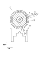
- FIG. 8 is a diagram illustrating a radial section and a refractive index distribution of the Yb-doped optical fiber 7.
- the Yb-doped optical fiber 7 is a triple-clad fiber having a clad 72 having a three-layer structure, an innermost cladding 72a is provided on the outer periphery of the core 71, and an intermediate cladding 72b is provided on the outer periphery of the innermost cladding 72a.
- the outermost cladding 72c is provided on the outer periphery of the intermediate cladding 72b, and the protective coating layer 73 is provided on the outer periphery of the outermost cladding 72c.
- the cross section of the intermediate clad 72b is a regular octagon, and the core 71, the innermost clad 72a, the intermediate clad 72b, and the outermost clad 72c are arranged concentrically.
- the fiber preform was produced by the VAD method. Yb was added by a liquid immersion method. At this time, the cylindrical fiber preform was cut off so that the cross-sectional shape was a regular octagon as shown in FIG. The obtained fiber preform was spun until the diameter of the circumscribed circle of the glass cross section was about 380 ⁇ m. At this time, a polymer clad material having a refractive index lower than that of the glass was applied and cured on the outer periphery of the glass so that excitation light was confined in the glass clad. Further, the outer periphery was coated with a protective UV curable resin.
- Yb 2 O 3 of the core is 0.68 mol%, P 2 O 5 / Yb 2 O 3 is 17.79, Al 2 O 3 / Yb 2 O 3 is 18.87, Al 2 O 3 / P 2 O 5 Was 1.06.
- the relative refractive index difference ( ⁇ ) of the core was 0.28%.
- the clad NA obtained from the difference in refractive index between the glass clad for guiding the excitation light and the polymer clad for confining the light was about 0.47. Almost no increase in loss due to photodarkening was observed in the obtained Yb-doped optical fiber, and the loss increase by the evaluation method was 0.01 dB or less.
- FIG. 9 is a diagram showing a radial section and a refractive index distribution of the Yb-doped optical fiber 8.
- the Yb-doped optical fiber 8 is a triple clad fiber having a two-layer core 81 and a three-layer clad 82.
- the ring groove 81b is provided on the outer periphery of the center core 81a
- the innermost cladding 82a is provided on the outer periphery of the ring groove 81b
- the intermediate cladding 82b is provided on the outer periphery of the innermost cladding 82a
- the outer periphery of the intermediate cladding 82b is provided on the outer periphery of the intermediate cladding 82b.
- the outermost clad 82c is provided on the upper surface
- the protective coating layer 83 is provided on the outer periphery of the outermost clad 82c.
- the cross-sectional shape of the intermediate clad 82b is a regular heptagon, and the center core 81a, ring groove 81b, innermost clad 82a, intermediate clad 82b, and outermost clad 82c are arranged concentrically.
- the fiber preform was produced by the MCVD method.
- Yb was added by a liquid immersion method.
- the cylindrical fiber preform was cut off so that the cross-sectional shape was a regular heptagon as shown in FIG.
- the obtained fiber preform was spun until the diameter of the circumscribed circle of the glass became about 400 ⁇ m.
- a polymer clad material having a refractive index lower than that of the glass was applied and cured on the outer periphery of the glass so that excitation light was confined in the glass clad. Further, the outer periphery was coated with a protective UV curable resin.
- the core Yb 2 O 3 is 0.28 mol%, P 2 O 5 / Yb 2 O 3 is 5.79, Al 2 O 3 / Yb 2 O 3 is 7.61, Al 2 O 3 / P 2 O 5 1.31 and GeO 2 was 0.83 mol%.
- the relative refractive index difference ( ⁇ ) of the core was 0.27%.
- the clad NA obtained from the difference in refractive index between the glass clad for guiding the excitation light and the polymer clad for confining the light was about 0.46. Almost no increase in loss due to photodarkening was observed in the obtained Yb-doped optical fiber, and the loss increase by the evaluation method was 0.01 dB or less.
- FIG. 10 is a diagram showing a radial section and a refractive index distribution of the Yb-doped optical fiber 9.
- the Yb-doped optical fiber 9 is a double clad fiber having a clad 92 having a two-layer structure.
- An inner clad 92a is provided on the outer circumference of the core 91
- an outer clad 92b is provided on the outer circumference of the inner clad 92a
- the outer clad is provided on the outer periphery of 92b.
- a pair of stress applying portions 94 and 94 are provided at positions symmetrical to the core 91. Furthermore, the cross-sectional shape of the inner cladding 92a is a regular octagon, and the core 91, the inner cladding 92a, and the outer cladding 92b are arranged concentrically.
- the fiber preform was produced by the MCVD method.
- Yb was added by a liquid immersion method.
- the cylindrical fiber preform was cut off so that the cross-sectional shape was a regular octagon as shown in FIG.
- a pair of holes were provided in the direction of the central axis of the fiber preform so as to be symmetrical with respect to the core, and stress-applied glass produced by adding boron or the like was inserted therein.
- the obtained fiber preform was spun until the diameter of the circumscribed circle of the glass became about 250 ⁇ m.
- a polymer clad material having a refractive index lower than that of the glass was applied and cured on the outer periphery of the glass so that excitation light was confined in the glass clad. Further, the outer periphery was coated with a protective UV curable resin.
- Yb 2 O 3 of the core is 0.60 mol%
- P 2 O 5 / Yb 2 O 3 is 19.17
- Al 2 O 3 / Yb 2 O 3 is 20.17
- Al 2 O 3 / P 2 O 5 A polarization-maintaining optical fiber with 1.05 and F of 0.40 mol% was obtained.
- the relative refractive index difference ( ⁇ ) of the core was 0.18%.
- the clad NA obtained from the difference in refractive index between the glass clad for guiding the excitation light and the polymer clad for confining the light was about 0.43. Almost no increase in loss due to photodarkening was observed in the obtained Yb-doped optical fiber, and the loss increase by the evaluation method was 0.01 dB or less.
- FIG. 11 is a diagram illustrating a radial cross section and a refractive index distribution of the Yb-doped optical fiber 10.
- the Yb-doped optical fiber 10 is a double-clad fiber having a clad 102 having a two-layer structure.
- An inner clad 102a is provided on the outer circumference of the core 101
- an outer clad 102b is provided on the outer circumference of the inner clad 102a
- a protective coating layer 103 is provided on the outer periphery of 102b.
- the cross-sectional shape of the inner cladding 102a is a regular octagon, and the core 101, the inner cladding 102a, and the outer cladding 102b are arranged concentrically.
- the fiber preform was produced by the VAD method.
- Yb was added by a liquid immersion method.
- the cylindrical fiber preform was cut off so that the cross-sectional shape was a regular octagon as shown in FIG.
- the obtained fiber preform was spun until the diameter of the circumscribed circle of the glass became about 420 ⁇ m.
- a polymer clad material having a refractive index lower than that of the glass was applied and cured on the outer periphery of the glass so that excitation light was confined in the glass clad. Further, the outer periphery was coated with a protective UV curable resin.
- Yb 2 O 3 of the core is 0.26 mol%
- P 2 O 5 / Yb 2 O 3 is 6.62
- Al 2 O 3 / Yb 2 O 3 is 9.04
- GeO 2 was 0.92 mol%
- F was 0.35 mol%.
- the relative refractive index difference ( ⁇ ) of the core was 0.21%.
- the clad NA obtained from the difference in refractive index between the glass clad for guiding the excitation light and the polymer clad for confining the light was about 0.46. Almost no increase in loss due to photodarkening was observed in the obtained Yb-doped optical fiber, and the loss increase by the evaluation method was 0.01 dB or less.
- Example 11 The addition of B in addition to Al, P, and Yb to the core, the addition amount of Al, P, and Yb are different, and the fiber preform that has been cut off so that the cross-sectional shape is D-shaped
- a double clad fiber was prepared in the same manner as in Example 4 except that spinning was performed until the diameter reached about 125 ⁇ m.
- the core Yb 2 O 3 is 0.31 mol%
- P 2 O 5 / Yb 2 O 3 is 22.29
- Al 2 O 3 / Yb 2 O 3 is 25.23
- Al 2 O 3 / P 2 O 5 Was 1.13
- B 2 O 5 was 0.3 mol.
- the relative refractive index difference ( ⁇ ) of the core was 0.22%.
- the clad NA obtained from the difference in refractive index between the glass clad for guiding the excitation light and the polymer clad for confining the light was about 0.46. Almost no increase in loss due to photodarkening was observed in the obtained Yb-doped optical fiber, and the loss increase by the evaluation method was 0.01 dB or less. Further, using the obtained Yb-doped optical fiber, a fiber laser was produced, and the temporal change in light output was evaluated. As a result, the amount of decrease in output after 100 hours was 1% or less with a pulse fiber laser having an initial output of 20.0 W. This output reduction amount includes not only an increase in optical fiber loss but also a cause due to temperature change and measurement variation. For this reason, it was considered that there was almost no decrease in output due to increased loss due to photodarkening. Table 2 shows the obtained Yb-doped optical fibers and the evaluation results.
- Tm is added to the core in addition to Al, P, Yb, the addition amount of Al, P, Yb is different, and the fiber preform cut off so that the cross-sectional shape becomes a regular octagonal shape
- a triple clad fiber was produced in the same manner as in Example 7 except that spinning was performed until the diameter reached about 250 ⁇ m.
- Tm was added by an immersion method.
- Yb 2 O 3 of the core is 0.25 mol%
- P 2 O 5 / Yb 2 O 3 is 25.80
- Al 2 O 3 / Yb 2 O 3 is 27.52
- the relative refractive index difference ( ⁇ ) of the core was 0.25%.
- the clad NA obtained from the difference in refractive index between the glass clad for guiding the excitation light and the polymer clad for confining the light was about 0.46. Almost no increase in loss due to photodarkening was observed in the obtained Yb-doped optical fiber, and the loss increase by the evaluation method was 0.01 dB or less. Further, using the obtained Yb-doped optical fiber, a fiber laser was produced, and the temporal change in light output was evaluated. As a result, the output decrease after 100 hours was 3% or less with the pulse fiber laser having an initial output of 15 W.
- This output reduction amount includes not only an increase in optical fiber loss but also a cause due to temperature change and measurement variation. Therefore, it was considered that the output decrease due to the loss increase due to photodarkening was 1% or less.
- Table 2 shows the obtained Yb-doped optical fibers and the evaluation results.
- Example 13 Addition of Nd to the core in addition to Al, P, and Yb, different amounts of addition of Al, P, and Yb, and fiber preforms cut off so that the cross-sectional shape is a regular heptagonal shape.
- a triple clad fiber was produced in the same manner as in Example 8, except that spinning was performed until the diameter reached about 250 ⁇ m.
- Nd was added by the immersion method.
- Yb 2 O 3 of the core is 0.30 mol%
- P 2 O 5 / Yb 2 O 3 is 13.67
- Al 2 O 3 / Yb 2 O 3 is 16.53
- Al 2 O 3 / P 2 O 5 1.21 and Nd 2 O 3 were 0.15 mol.
- the relative refractive index difference ( ⁇ ) of the core was 0.18%.
- the clad NA obtained from the difference in refractive index between the glass clad for guiding the excitation light and the polymer clad for confining the light was about 0.43. Almost no increase in loss due to photodarkening was observed in the obtained Yb-doped optical fiber, and the loss increase by the evaluation method was 0.01 dB or less. Further, using the obtained Yb-doped optical fiber, a fiber laser was produced, and the temporal change in light output was evaluated. As a result, the output decrease after 100 hours was 1% or less with the pulsed fiber laser having an initial output of 15.8 W.
- This output reduction amount includes not only an increase in optical fiber loss but also a cause due to temperature change and measurement variation. Therefore, it was considered that the output decrease due to the loss increase due to photodarkening was 1% or less.
- Table 3 shows the obtained Yb-doped optical fibers and the evaluation results.
- Example 1 Example except that Al, Yb, Ge were added to the core, P was not added, the addition amount of Al, Yb was different, and the fiber preform was spun until the glass outer diameter was about 200 ⁇ m.
- a single clad fiber was produced.
- the core Yb 2 O 3 was 0.51 mol%
- Al 2 O 3 / Yb 2 O 3 was 0.39
- Al 2 O 3 was 0.2 mol%
- GeO 2 was 0.23 mol%. That is, Al 2 O 3 / Yb 2 O 3 was outside the scope of the present invention.
- the relative refractive index difference ( ⁇ ) of the core was 0.27%.
- the obtained Yb-doped optical fiber had a large loss increase due to photodarkening, and the loss increase amount by the evaluation method was 3.8 dB. Therefore, a fiber laser was produced using the obtained Yb-doped optical fiber, and the temporal change in the optical output was evaluated. As a result, the amount of decrease in output after 30 hours with a pulse fiber laser with an initial output of 20 W was 30% or more. Met. Table 3 shows the obtained Yb-doped optical fibers and the evaluation results.
- the relative refractive index difference ( ⁇ ) of the core was 0.20%.
- the clad NA obtained from the difference in refractive index between the glass clad for guiding the excitation light and the polymer clad for confining the light was about 0.43.
- the obtained Yb-doped optical fiber had a large loss increase due to photodarkening, and the loss increase amount by the evaluation method was 10.6 dB.
- FIG. 12 is a graph showing the relationship between the amount of loss before and after excitation light irradiation and the difference wavelength.
- the output decrease after 100 hours with a pulse fiber laser with an initial output of 12 W is 50% or more.
- Table 3 shows the obtained Yb-doped optical fibers and the evaluation results.
- a double clad fiber was produced in the same manner as in Example 2 except that the addition amounts of Al, P, and Yb were different, and that the polymer clad material was coated and cured to form a double clad structure.
- Yb 2 O 3 of the core is 0.45 mol%
- P 2 O 5 / Yb 2 O 3 is 30.7
- Al 2 O 3 / Yb 2 O 3 is 31.1
- Al 2 O 3 / P 2 O 5 Was 1.01. That is, P 2 O 5 / Yb 2 O 3 was outside the scope of the present invention.
- the relative refractive index difference ( ⁇ ) of the core was 0.27%.
- the clad NA obtained from the difference in refractive index between the glass clad for guiding the excitation light and the polymer clad for confining the light was about 0.46.
- the obtained Yb-doped optical fiber had a large transmission loss and reached about 160 dB / km. Therefore, using the obtained Yb-doped optical fiber, a fiber laser was fabricated and the optical output was evaluated. As a result, the initial output could be realized only up to 6W.
- Table 4 shows the obtained Yb-doped optical fiber and its evaluation results.
- a double clad fiber was prepared in the same manner as in Example 5 except that the addition amounts of Al, P, and Yb were different.
- the core Yb 2 O 3 is 0.22 mol%
- P 2 O 5 / Yb 2 O 3 is 2.14
- Al 2 O 3 / Yb 2 O 3 is 4.91
- Al 2 O 3 / P 2 O 5 was outside the scope of the present invention.
- the relative refractive index difference ( ⁇ ) of the core was 0.30%.
- the clad NA obtained from the refractive index difference between the glass clad for guiding the excitation light and the polymer clad for confining the light was about 0.44.
- the obtained Yb-doped optical fiber had a large loss increase due to photodarkening, and the loss increase amount by the evaluation method was 1.7 dB. Therefore, a fiber laser was manufactured using the obtained Yb-doped optical fiber, and the temporal change in the optical output was evaluated. As a result, the amount of output decrease after 100 hours with a pulsed fiber laser with an initial output of 12 W was 25% or more. Met. Table 4 shows the obtained Yb-doped optical fiber and its evaluation results.
- Example 6 A single clad fiber was produced in the same manner as in Example 2 except that the addition amounts of Al, P, and Yb were different.
- the core Yb 2 O 3 is 0.28 mol%
- P 2 O 5 / Yb 2 O 3 is 20.29
- Al 2 O 3 / Yb 2 O 3 is 38.57
- Al 2 O 3 / P 2 O 5 was 1.90. That is, Al 2 O 3 / Yb 2 O 3 was outside the scope of the present invention.
- the relative refractive index difference ( ⁇ ) of the core was 0.55%.
- the loss increase amount of the obtained Yb-doped optical fiber by the evaluation method was about 0.01 dB or less.
- the mode field diameter of the optical fiber was reduced because of the large relative refractive index difference ( ⁇ ). For this reason, stimulated Raman scattering occurs, and only a fiber laser with an initial output of 5 W can be realized. Further, as a result of producing a fiber laser using the obtained Yb-doped optical fiber and evaluating the temporal change of the optical output, the output decrease after 100 hours is 8% or more with a pulse fiber laser with an initial output of 5 W. Met. Table 4 shows the obtained Yb-doped optical fiber and its evaluation results.
- a double clad fiber was produced in the same manner as in Example 6 except that the addition amounts of Al, P, and Yb were different.
- the core Yb 2 O 3 is 0.48 mol%
- P 2 O 5 / Yb 2 O 3 is 9.02
- Al 2 O 3 / Yb 2 O 3 is 24.38
- Al 2 O 3 / P 2 O 5 was 2.70. That is, Al 2 O 3 / P 2 O 5 was outside the scope of the present invention.
- the relative refractive index difference ( ⁇ ) of the core was 0.85%.
- the clad NA obtained from the difference in refractive index between the glass clad for guiding the excitation light and the polymer clad for confining the light was about 0.46.
- the mode field diameter of the optical fiber was small due to the large relative refractive index difference ( ⁇ ). Therefore, stimulated Raman scattering occurs, and only a fiber laser with an initial output of 7 W can be realized.
- Table 4 shows the obtained Yb-doped optical fiber and its evaluation results.
- the present invention can be used as a laser medium for a high-power light source for material processing applications such as welding, marking, and cutting.
Abstract
Disclosed is a ytterbium-doped optical fiber comprising a core containing at least ytterbium, aluminum and phosphorus, and a cladding surrounding the core. The ytterbium concentration in the core in terms of ytterbium oxide is 0.09-0.68% by mole; the molar ratio between the phosphorus concentration in the core in terms of diphosphorus pentoxide and the above-described ytterbium concentration in terms of ytterbium oxide is 3-30; the molar ratio between the aluminum concentration in the core in terms of aluminum oxide and the above-described ytterbium concentration in terms of ytterbium oxide is 3-32; and the molar ratio between the above-described aluminum concentration in terms of aluminum oxide and the above-described phosphorus concentration in terms of diphosphorus pentoxide is 1-2.5.
Description
本発明は、フォトダークニングが抑制されたイッテルビウム添加光ファイバ、並びに該光ファイバを有するファイバレーザ及びファイバアンプに関する。
本願は、2008年11月14日に、日本国に出願された特願2008-292013号に基づき優先権を主張し、その内容をここに援用する。 The present invention relates to an ytterbium-doped optical fiber in which photodarkening is suppressed, and a fiber laser and a fiber amplifier having the optical fiber.
This application claims priority based on Japanese Patent Application No. 2008-292013 filed in Japan on November 14, 2008, the contents of which are incorporated herein by reference.
希土類元素が添加された光ファイバ内では、この希土類元素の励起光が供給されると、反転分布が形成される。そのため、この励起光の波長に対応した波長を有する誘導放出光が生じる。そこで、このような希土類添加光ファイバは、誘導放出光の波長と同じ波長を有する信号光を増幅するファイバアンプや、誘導放出光の波長と同じ波長を有するレーザ発振光を出力するファイバレーザに広く利用されている。そして、ファイバアンプやファイバレーザには、より広い波長帯域において、高く且つ平坦な利得特性や発振特性を有することが望まれている。このような観点から、希土類添加光ファイバの研究開発が展開されている。
希土類添加光ファイバとしては、例えば、イッテルビウム(Yb)添加光ファイバが知られている。このYb添加光ファイバは、ビーム品質の良い高パワー出力光が得られる。この出力光の発振波長は、既存の高出力レーザの一つであるNd-YAGとほぼ同じ1μm付近である。そのため、溶接、マーキング、切断等の材料加工用途の高出力光源用レーザ媒体としての実用化が期待されている。 In the optical fiber to which the rare earth element is added, when an excitation light of the rare earth element is supplied, an inversion distribution is formed. Therefore, stimulated emission light having a wavelength corresponding to the wavelength of the excitation light is generated. Therefore, such rare earth-doped optical fibers are widely used for fiber amplifiers that amplify signal light having the same wavelength as stimulated emission light and fiber lasers that output laser oscillation light having the same wavelength as stimulated emission light. It's being used. And it is desired for fiber amplifiers and fiber lasers to have high and flat gain characteristics and oscillation characteristics in a wider wavelength band. From this point of view, research and development of rare earth-doped optical fibers are being developed.
As a rare earth doped optical fiber, for example, an ytterbium (Yb) doped optical fiber is known. This Yb-doped optical fiber provides high power output light with good beam quality. The oscillation wavelength of this output light is about 1 μm, which is almost the same as that of Nd-YAG, which is one of existing high-power lasers. Therefore, it is expected to be put to practical use as a laser medium for a high-output light source for material processing applications such as welding, marking, and cutting.
図13は、従来のYb添加光ファイバの径方向の断面及び屈折率分布を例示する図である。
ここに示すYb添加光ファイバ110は、シングルクラッドファイバであり、コア111の外周上にクラッド112を設け、このクラッド112の外周上に保護被覆層113を設けたものである。Yb添加光ファイバ110では、導波する光を閉じ込めるために、コア111の屈折率がクラッド112の屈折率よりも高くなっている。コア111の屈折率を高くするためには、通常、ゲルマニウム(Ge)、アルミニウム(Al)、リン(P)等の屈折率上昇ドーパントがコア111に添加される。さらに、コア111には光増幅作用を有するドーパントとして、Ybが添加される。Ybは、通常、コア111中にほぼ均一な濃度分布となるように添加されるが、濃度分布があっても良く、さらにクラッド112の一部に添加されても良い。
このようなYb添加光ファイバに励起光を入射させ、信号光を入射させるか又はファイバブラッググレーティング等を使用してキャビティを組むことで、高パワーの信号光が得られる。 FIG. 13 is a diagram illustrating a radial cross section and a refractive index distribution of a conventional Yb-doped optical fiber.
The Yb-dopedoptical fiber 110 shown here is a single clad fiber, in which a clad 112 is provided on the outer periphery of the core 111, and a protective coating layer 113 is provided on the outer periphery of the clad 112. In the Yb-doped optical fiber 110, the refractive index of the core 111 is higher than the refractive index of the cladding 112 in order to confine the guided light. In order to increase the refractive index of the core 111, a refractive index increasing dopant such as germanium (Ge), aluminum (Al), or phosphorus (P) is usually added to the core 111. Further, Yb is added to the core 111 as a dopant having an optical amplification function. Yb is usually added so as to have a substantially uniform concentration distribution in the core 111, but may have a concentration distribution, and may be added to a part of the cladding 112.
High power signal light can be obtained by making excitation light incident on such a Yb-doped optical fiber and making signal light incident or by forming a cavity using a fiber Bragg grating or the like.
ここに示すYb添加光ファイバ110は、シングルクラッドファイバであり、コア111の外周上にクラッド112を設け、このクラッド112の外周上に保護被覆層113を設けたものである。Yb添加光ファイバ110では、導波する光を閉じ込めるために、コア111の屈折率がクラッド112の屈折率よりも高くなっている。コア111の屈折率を高くするためには、通常、ゲルマニウム(Ge)、アルミニウム(Al)、リン(P)等の屈折率上昇ドーパントがコア111に添加される。さらに、コア111には光増幅作用を有するドーパントとして、Ybが添加される。Ybは、通常、コア111中にほぼ均一な濃度分布となるように添加されるが、濃度分布があっても良く、さらにクラッド112の一部に添加されても良い。
このようなYb添加光ファイバに励起光を入射させ、信号光を入射させるか又はファイバブラッググレーティング等を使用してキャビティを組むことで、高パワーの信号光が得られる。 FIG. 13 is a diagram illustrating a radial cross section and a refractive index distribution of a conventional Yb-doped optical fiber.
The Yb-doped
High power signal light can be obtained by making excitation light incident on such a Yb-doped optical fiber and making signal light incident or by forming a cavity using a fiber Bragg grating or the like.
通常、ファイバレーザやファイバアンプの光増幅媒体としてYb添加光ファイバを使用する場合には、限定モード励振が可能で冷却効率が高いファイバ型光増幅媒体の利点を生かすために、実質的なシングルモード条件でYb添加光ファイバを使用することが多い。
実質的にシングルモード伝播させるための光導波路の条件は、コアの屈折率とコア径(換言すれば、コアの径方向における屈折率分布)、巻き径等の条件によって決定される。この際、コアの屈折率が低いか、又はコア径が小さいことが必要となる。
一方、光増幅媒体としての性能を考慮すると、より高パワーの光が出力できることが望まれる。すなわち、高パワーの光を光ファイバ中に伝播可能なことが、より良い増幅用光ファイバの条件である。しかし、光量が同等な光を、コア径が小さい光ファイバに入射させた場合と、コア径が大きい光ファイバに入射させた場合とで比較すると、前者の方が後者よりも光の伝送断面積(モードフィールド径)が小さいので、コアを伝播する光のパワー密度が高くなる。その結果、光によるコアガラスの損傷や光学的非線形現象を誘発し易い。あるいは、光伝送時の増幅パワーが制限されてしまう。したがって、このような観点からは、コア径が大きい方が望ましい。以上より、コア径を大きくし、かつシングルモード伝播させるためには、コアの屈折率を低くすることが必要となる。 Normally, when using a Yb-doped optical fiber as an optical amplifying medium for fiber lasers or fiber amplifiers, it is possible to use a substantially single mode in order to take advantage of a fiber-type optical amplifying medium capable of limited mode excitation and high cooling efficiency. A Yb-doped optical fiber is often used under certain conditions.
The conditions of the optical waveguide for substantially single mode propagation are determined by conditions such as the refractive index of the core, the core diameter (in other words, the refractive index distribution in the radial direction of the core), and the winding diameter. At this time, it is necessary that the refractive index of the core is low or the core diameter is small.
On the other hand, considering the performance as an optical amplification medium, it is desired that higher power light can be output. That is, it is a condition for a better amplification optical fiber that high power light can be propagated into the optical fiber. However, when comparing the case where light with the same light quantity is incident on an optical fiber having a small core diameter and the case where it is incident on an optical fiber having a large core diameter, the former has a light transmission cross-sectional area larger than that of the latter. Since (mode field diameter) is small, the power density of light propagating through the core is increased. As a result, it is easy to induce damage to the core glass and optical nonlinear phenomenon due to light. Alternatively, the amplification power during optical transmission is limited. Therefore, from this point of view, a larger core diameter is desirable. From the above, in order to increase the core diameter and propagate the single mode, it is necessary to lower the refractive index of the core.
ファイバアンプやファイバレーザの特性を悪化させる要因の一つに、ファイバ中を伝播する励起光や信号光によって生じる光ファイバの損失増加(フォトダークニング)がある(非特許文献1及び2参照)。この損失増加によって、光増幅媒体である希土類添加光ファイバの光増幅効率が徐々に低下する。その結果、ファイバアンプやファイバレーザは、経時に伴い出力が低下して、寿命が短くなってしまう。
One factor that deteriorates the characteristics of fiber amplifiers and fiber lasers is an increase in optical fiber loss (photodarkening) caused by pumping light and signal light propagating in the fiber (see Non-Patent Documents 1 and 2). Due to this increase in loss, the optical amplification efficiency of the rare earth-doped optical fiber, which is an optical amplification medium, gradually decreases. As a result, the output of the fiber amplifier or the fiber laser decreases with time and the life is shortened.
そこで、これまでにフォトダークニングを抑制するための手法が種々開示されている。
例えば、非特許文献1には、DND(Direct Nanoparticle Deposition)と呼ばれる特殊な製造方法を適用することで、フォトダークニングを抑制することが開示されている。
また、非特許文献2には、光ファイバの製造時にアルミニウムを高濃度に添加することによって、フォトダークニングを抑制することが開示されている。
また、非特許文献3には、光ファイバの製造時にリンを高濃度に添加することによって、フォトダークニングを抑制することが開示されている。
また、特許文献1には、光ファイバに水素を添加することで、フォトダークニングを抑制することが開示されている。
S.Tammela et al., The Potential of Direct Nanoparticle Deposition for the Next Generation of Optical Fibers, The Proceeding of SPIE Photonics West 2006, Vol.6116-16 (2006) T. Kitabayashi et. al., Population Inversion Factor Dependence of Photodarkening of Yb-doped Fibers and Its Suppression by Highly Aluminum Doping, The Proceedings of OFC 2006, OThC5(2006) M. Engholm et. al., Preventing photodarkening in ytterbium-doped high power fiber laser; correlation to the UV-transparency of the core glass, The Proceeding of Optics Express Vol.16, 1260-1268 (2008) 特開2007-114335号公報
Thus, various techniques for suppressing photodarkening have been disclosed so far.
For example, Non-PatentDocument 1 discloses that photodarkening is suppressed by applying a special manufacturing method called DND (Direct Nanoparticle Deposition).
Non-PatentDocument 2 discloses that photodarkening is suppressed by adding aluminum at a high concentration during the production of an optical fiber.
Non-PatentDocument 3 discloses that photodarkening is suppressed by adding phosphorus at a high concentration during the production of an optical fiber.
Patent Document 1 discloses that photodarkening is suppressed by adding hydrogen to an optical fiber.
S. Tammela et al., The Potential of Direct Nanoparticle Deposition for the Next Generation of Optical Fibers, The Proceeding of SPIE Photonics West 2006, Vol. 6116-16 (2006) T. Kitabayashi et.al., Population Inversion Factor Dependence of Photodarkening of Yb-doped Fibers and Its Suppression by Highly Aluminum Doping, The Proceedings of OFC 2006, OThC5 (2006) M. Engholm et. Al., Preventing photodarkening in ytterbium-doped high power fiber laser; correlation to the UV-transparency of the core glass, The Proceeding of Optics Express Vol. 16, 1260-1268 (2008) JP 2007-114335 A
例えば、非特許文献1には、DND(Direct Nanoparticle Deposition)と呼ばれる特殊な製造方法を適用することで、フォトダークニングを抑制することが開示されている。
また、非特許文献2には、光ファイバの製造時にアルミニウムを高濃度に添加することによって、フォトダークニングを抑制することが開示されている。
また、非特許文献3には、光ファイバの製造時にリンを高濃度に添加することによって、フォトダークニングを抑制することが開示されている。
また、特許文献1には、光ファイバに水素を添加することで、フォトダークニングを抑制することが開示されている。
S.Tammela et al., The Potential of Direct Nanoparticle Deposition for the Next Generation of Optical Fibers, The Proceeding of SPIE Photonics West 2006, Vol.6116-16 (2006) T. Kitabayashi et. al., Population Inversion Factor Dependence of Photodarkening of Yb-doped Fibers and Its Suppression by Highly Aluminum Doping, The Proceedings of OFC 2006, OThC5(2006) M. Engholm et. al., Preventing photodarkening in ytterbium-doped high power fiber laser; correlation to the UV-transparency of the core glass, The Proceeding of Optics Express Vol.16, 1260-1268 (2008)
For example, Non-Patent
Non-Patent
Non-Patent
S. Tammela et al., The Potential of Direct Nanoparticle Deposition for the Next Generation of Optical Fibers, The Proceeding of SPIE Photonics West 2006, Vol. 6116-16 (2006) T. Kitabayashi et.al., Population Inversion Factor Dependence of Photodarkening of Yb-doped Fibers and Its Suppression by Highly Aluminum Doping, The Proceedings of OFC 2006, OThC5 (2006) M. Engholm et. Al., Preventing photodarkening in ytterbium-doped high power fiber laser; correlation to the UV-transparency of the core glass, The Proceeding of Optics Express Vol. 16, 1260-1268 (2008)
しかし、非特許文献1に記載の方法によれば、従来法で製造した場合よりも確かにフォトダークニングは抑制できるが、その抑制効果はまだ不十分である。また、製造方法が特殊なため、従来法であるMCVD法やVAD法と比較して、光ファイバにはOH基の混入が多くなる。そのため、このOH基に起因する損失が大きくなってしまう。さらに、製造に使用するファイバプリフォームのサイズが制限されてしまうので、製造コストが上昇する。そのため、フォトダークニングが抑制された光増幅用光ファイバを安価に製造できない。
非特許文献2に記載の方法では、フォトダークニングを十分抑制するために、多量のアルミニウムが必要となる。その結果、光ファイバのコアの屈折率が高くなってしまう。非特許文献3に記載の方法では、フォトダークニングを十分抑制するために、多量のリンが必要となる。この場合も、非特許文献2に記載の方法と同様に、光ファイバのコアの屈折率が高くなってしまう。このようにコアの屈折率が高い場合、光ファイバをシングルモード動作させるために、コア径を小さくする必要があるが、上記のように、所望の出力光が得られなくなってしまうという問題点があった。
特許文献1に記載の方法によれば、フォトダークニングを抑制できるが、水素含浸工程と光照射工程が必要となる。そのため、製造工程が煩雑となり、大量の光ファイバを製造することが困難である。 However, according to the method described in Non-PatentDocument 1, the photodarkening can surely be suppressed as compared with the case of manufacturing by the conventional method, but the suppression effect is still insufficient. Further, since the manufacturing method is special, OH groups are mixed in the optical fiber more than the conventional MCVD method and VAD method. Therefore, the loss due to the OH group becomes large. Furthermore, since the size of the fiber preform used for manufacture is limited, the manufacturing cost increases. Therefore, an optical fiber for optical amplification in which photodarkening is suppressed cannot be manufactured at low cost.
The method described in Non-PatentDocument 2 requires a large amount of aluminum in order to sufficiently suppress photodarkening. As a result, the refractive index of the core of the optical fiber becomes high. The method described in Non-Patent Document 3 requires a large amount of phosphorus in order to sufficiently suppress photodarkening. Also in this case, like the method described in Non-Patent Document 2, the refractive index of the core of the optical fiber becomes high. When the refractive index of the core is high as described above, it is necessary to reduce the core diameter in order to operate the optical fiber in a single mode. However, as described above, there is a problem that desired output light cannot be obtained. there were.
According to the method described inPatent Document 1, photodarkening can be suppressed, but a hydrogen impregnation step and a light irradiation step are required. Therefore, a manufacturing process becomes complicated and it is difficult to manufacture a large amount of optical fibers.
非特許文献2に記載の方法では、フォトダークニングを十分抑制するために、多量のアルミニウムが必要となる。その結果、光ファイバのコアの屈折率が高くなってしまう。非特許文献3に記載の方法では、フォトダークニングを十分抑制するために、多量のリンが必要となる。この場合も、非特許文献2に記載の方法と同様に、光ファイバのコアの屈折率が高くなってしまう。このようにコアの屈折率が高い場合、光ファイバをシングルモード動作させるために、コア径を小さくする必要があるが、上記のように、所望の出力光が得られなくなってしまうという問題点があった。
特許文献1に記載の方法によれば、フォトダークニングを抑制できるが、水素含浸工程と光照射工程が必要となる。そのため、製造工程が煩雑となり、大量の光ファイバを製造することが困難である。 However, according to the method described in Non-Patent
The method described in Non-Patent
According to the method described in
本発明は、上記事情に鑑みてなされたものであり、従来法で製造可能な、フォトダークニングが抑制された光ファイバの提供を課題とする。
The present invention has been made in view of the above circumstances, and an object thereof is to provide an optical fiber that can be manufactured by a conventional method and in which photodarkening is suppressed.
本発明は、上記課題を解決して係る目的を達成するために以下の手段を採用した。
(1)本発明のイッテルビウム添加光ファイバは、イッテルビウム、アルミニウム及びリンを少なくとも含有するコアと、このコアを囲むクラッドと、を備え、前記コア中の、前記イッテルビウムの酸化イッテルビウム換算濃度が0.09~0.68モル%であり、前記コア中の、前記リンの五酸化二リン換算濃度と前記酸化イッテルビウム換算濃度とのモル比が3~30であり、前記コア中の、前記アルミニウムの酸化アルミニウム換算濃度と前記酸化イッテルビウム換算濃度とのモル比が3~32であり、前記酸化アルミニウム換算濃度と前記五酸化二リン換算濃度とのモル比が1~2.5である。
(2)前記コア及び前記クラッドがシリカガラスで構成されているのが好ましい。
(3)前記五酸化二リン換算濃度と前記酸化イッテルビウム換算濃度とのモル比が5~30であり、前記酸化アルミニウム換算濃度と前記酸化イッテルビウム換算濃度とのモル比が5~32であるのが好ましい。
(4)前記酸化アルミニウム換算濃度及び前記五酸化二リン換算濃度が、いずれも8モル%以下であるのが好ましい。
(5)前記コアと前記クラッドとの比屈折率差が0.05~0.3%であるのが好ましい。
(6)前記コアと前記クラッドとの比屈折率差が0.1~0.25%であるのが好ましい。
(7)前記コアが、さらにゲルマニウムを含有するのが好ましい。
(8)前記コアが、さらにフッ素及び/又はホウ素を含有するのが好ましい。
(9)前記コアが、さらに前記イッテルビウム以外の希土類元素及び遷移金属元素からなる群から選択される少なくとも一種を含有するのが好ましい。
(10)前記クラッドを少なくとも二層備え、径方向内側のクラッドの屈折率が外側のクラッドの屈折率よりも高いのが好ましい。
(11)前記クラッドを少なくとも三層備え、径方向最内側のクラッドの屈折率nc1と、最外側のクラッドの屈折率nc3と、前記最内側及び前記最外側のクラッド間の中間クラッドの屈折率nc2とが、nc1>nc2>nc3の関係を満たすのが好ましい。
(12)本発明のファイバレーザは、上記(1)に記載のイッテルビウム添加光ファイバを光増幅媒体として有する。
(13)本発明のファイバアンプは、上記(1)に記載のイッテルビウム添加光ファイバを光増幅媒体として有する。 The present invention employs the following means in order to solve the above problems and achieve the object.
(1) The ytterbium-doped optical fiber of the present invention includes a core containing at least ytterbium, aluminum, and phosphorus, and a clad surrounding the core, and the ytterbium oxide equivalent concentration of the ytterbium in the core is 0.09. 0.68 mol%, and the molar ratio of the phosphorous pentoxide equivalent concentration and the ytterbium oxide equivalent concentration of the phosphorus in the core is 3 to 30, and the aluminum oxide of the aluminum in the core The molar ratio between the equivalent concentration and the ytterbium oxide equivalent concentration is 3 to 32, and the molar ratio between the aluminum oxide equivalent concentration and the diphosphorus pentoxide equivalent concentration is 1 to 2.5.
(2) The core and the clad are preferably made of silica glass.
(3) The molar ratio between the diphosphorus pentoxide equivalent concentration and the ytterbium oxide equivalent concentration is 5 to 30, and the molar ratio between the aluminum oxide equivalent concentration and the ytterbium oxide equivalent concentration is 5 to 32. preferable.
(4) The aluminum oxide equivalent concentration and the diphosphorus pentoxide equivalent concentration are both preferably 8 mol% or less.
(5) It is preferable that a relative refractive index difference between the core and the clad is 0.05 to 0.3%.
(6) The relative refractive index difference between the core and the clad is preferably 0.1 to 0.25%.
(7) It is preferable that the core further contains germanium.
(8) It is preferable that the core further contains fluorine and / or boron.
(9) It is preferable that the core further contains at least one selected from the group consisting of rare earth elements other than the ytterbium and transition metal elements.
(10) Preferably, the clad is provided with at least two layers, and the refractive index of the radially inner clad is higher than the refractive index of the outer clad.
(11) The clad is provided with at least three layers, the refractive index nc1 of the radially innermost clad, the refractive index nc3 of the outermost clad, and the refractive index nc2 of the intermediate clad between the innermost and outermost clads. Preferably satisfy the relationship of nc1>nc2> nc3.
(12) A fiber laser of the present invention has the ytterbium-doped optical fiber described in (1) above as an optical amplification medium.
(13) The fiber amplifier of the present invention includes the ytterbium-doped optical fiber described in (1) above as an optical amplification medium.
上記(1)に記載のイッテルビウム添加光ファイバによれば、フォトダークニングが抑制され、優れた光増幅効果が得られる光ファイバを、安価かつ大量に提供できる。また、このような光ファイバを光増幅媒体として使用することで、経時に伴う出力低下が抑制され、光学特性が良好なファイバレーザ及びファイバアンプを安価に提供できる。
According to the ytterbium-doped optical fiber described in (1) above, it is possible to provide an inexpensive and large amount of optical fiber that can suppress photodarkening and obtain an excellent optical amplification effect. Further, by using such an optical fiber as an optical amplifying medium, it is possible to provide a fiber laser and a fiber amplifier having low optical output and good optical characteristics at low cost.
1,2,3,4,5,6,7,8,9,10 イッテルビウム添加光ファイバ
11,21,31,41,51,61,71,81,91,101 コア
12,22,32,42,52,62,72,82,92,102 クラッド
42a,52a,62a,92a,102a 内側クラッド
42b,52b,62b,92b,102b 外側クラッド
72a,82a 最内側クラッド
72b,82b 中間クラッド
72c,82c 最外側クラッド 1,2,3,4,5,6,7,8,9,10 Ytterbium-doped optical fiber 11, 21, 31, 41, 51, 61, 71, 81, 91, 101 Core 12, 22, 32, 42 , 52, 62, 72, 82, 92, 102 Cladding 42a, 52a, 62a, 92a, 102a Inner cladding 42b, 52b, 62b, 92b, 102b Outer cladding 72a, 82a Innermost cladding 72b, 82b Intermediate cladding 72c, 82c Outer cladding
11,21,31,41,51,61,71,81,91,101 コア
12,22,32,42,52,62,72,82,92,102 クラッド
42a,52a,62a,92a,102a 内側クラッド
42b,52b,62b,92b,102b 外側クラッド
72a,82a 最内側クラッド
72b,82b 中間クラッド
72c,82c 最外側クラッド 1,2,3,4,5,6,7,8,9,10 Ytterbium-doped
以下、本発明について詳しく説明する。
以下で「モル%」の単位で示す添加成分の濃度は、屈折率分布を有する光ファイバにおいては、特に断りのない限り平均値である。 The present invention will be described in detail below.
In the following, the concentration of the additive component shown in the unit of “mol%” is an average value unless otherwise specified in an optical fiber having a refractive index distribution.
<Yb添加光ファイバ>
本発明のYb添加光ファイバは、コアと、このコアを囲むクラッドを備える。前記コアは、少なくともYb、Al及びPを含有する。前記コア中の、Ybの酸化イッテルビウム(Yb2O3)換算濃度(以下、単に「Yb2O3換算濃度」と略記することがある)、Pの五酸化二リン(P2O5)換算濃度(以下、単に「P2O5換算濃度」と略記することがある)及びAlの酸化アルミニウム(Al2O3)換算濃度(以下、単に「Al2O3換算濃度」と略記することがある)が下記条件を満たす。
(A)Yb2O3換算濃度が0.09~0.68モル%である。
(B)P2O5換算濃度とYb2O3換算濃度とのモル比(P2O5換算濃度(モル%)/Yb2O3換算濃度(モル%))が3~30である。
(C)Al2O3換算濃度とYb2O3換算濃度とのモル比(Al2O3換算濃度(モル%)/Yb2O3換算濃度(モル%))が3~32である。
(D)Al2O3換算濃度とP2O5換算濃度とのモル比(Al2O3換算濃度(モル%)/P2O5換算濃度(モル%))が1~2.5である。 <Yb-doped optical fiber>
The Yb-doped optical fiber of the present invention includes a core and a clad surrounding the core. The core contains at least Yb, Al, and P. Yb ytterbium oxide (Yb 2 O 3 ) equivalent concentration in the core (hereinafter sometimes simply referred to as “Yb 2 O 3 equivalent concentration”), P diphosphorus pentoxide (P 2 O 5 ) equivalent Concentration (hereinafter sometimes simply referred to as “P 2 O 5 equivalent concentration”) and Al aluminum oxide (Al 2 O 3 ) equivalent concentration (hereinafter simply referred to as “Al 2 O 3 equivalent concentration”) There are conditions that meet the following conditions.
(A) The Yb 2 O 3 equivalent concentration is 0.09 to 0.68 mol%.
(B) The molar ratio of P 2 O 5 equivalent concentration to Yb 2 O 3 equivalent concentration (P 2 O 5 equivalent concentration (mol%) / Yb 2 O 3 equivalent concentration (mol%)) is 3 to 30.
(C) The molar ratio of the Al 2 O 3 equivalent concentration to the Yb 2 O 3 equivalent concentration (Al 2 O 3 equivalent concentration (mol%) / Yb 2 O 3 equivalent concentration (mol%)) is 3 to 32.
(D) The molar ratio of the Al 2 O 3 equivalent concentration to the P 2 O 5 equivalent concentration (Al 2 O 3 equivalent concentration (mol%) / P 2 O 5 equivalent concentration (mol%)) is 1 to 2.5. is there.
Ybは光増幅作用を有するドーパントである。Alは屈折率上昇作用及びガラスの結晶化抑制作用を有するドーパントである。Pはフォトダークニング抑制作用及び屈折率上昇作用を有するドーパントである。
Yb is a dopant having an optical amplification effect. Al is a dopant having a refractive index increasing action and a glass crystallization inhibiting action. P is a dopant having a photodarkening suppressing action and a refractive index raising action.
コア中のPは、フォトダークニングの抑制作用を有する。しかしながら、コアがYb及びPのみを含有する光ファイバは、コアの屈折率を所望の低い値とした場合、ガラスが結晶化してしまう。そのため、この光ファイバは、増幅用光ファイバとして使用できない。しかし、さらにAlをコアに含有させることにより、フォトダークニングを抑制しつつ、コアの屈折率を所望の低い値にしても、ガラスの結晶化を抑制できる。Alがガラスの結晶化抑制作用を有するのは、Yb及びPをガラス中に分散させるからであると推測される。しかも、特筆すべきは、AlとPを共に含有させることで、屈折率を低下させる効果がある。
本発明は、コア中のYb2O3換算濃度、P2O5換算濃度及びAl2O3換算濃度を、上記(A)~(D)の条件を満たすようにそれぞれ所定の範囲に設定することで、フォトダークニングの抑制とガラスの結晶化抑制とを高いレベルで両立でき、しかもより優れた光増幅効果が得られる。 P in the core has an action of suppressing photodarkening. However, in the optical fiber in which the core contains only Yb and P, when the refractive index of the core is set to a desired low value, the glass is crystallized. Therefore, this optical fiber cannot be used as an amplification optical fiber. However, by further containing Al in the core, crystallization of the glass can be suppressed even when the refractive index of the core is set to a desired low value while suppressing photodarkening. It is presumed that Al has an action of suppressing crystallization of glass because Yb and P are dispersed in the glass. In addition, it should be noted that the inclusion of both Al and P has the effect of reducing the refractive index.
In the present invention, the Yb 2 O 3 equivalent concentration, the P 2 O 5 equivalent concentration, and the Al 2 O 3 equivalent concentration in the core are set within predetermined ranges so as to satisfy the above conditions (A) to (D). Thus, suppression of photodarkening and suppression of crystallization of glass can be achieved at a high level, and a more excellent light amplification effect can be obtained.
上記のような観点から、本発明においては、コア中のYb2O3換算濃度を0.09~0.68モル%とする。0.09モル%以上とすることで、十分な光増幅効果が得られる。具体的には、Yb添加光ファイバをファイバアンプやファイバレーザへ適用した場合に、概ね10dB以上の良好な増幅効果が得られる。また、0.68モル%以下とすることで、コアの屈折率の上昇を許容範囲内に抑制でき、コアとクラッドとの比屈折率差(Δ)を0.3%以下にできる。
From the above viewpoint, in the present invention, the Yb 2 O 3 equivalent concentration in the core is 0.09 to 0.68 mol%. By setting it to 0.09 mol% or more, a sufficient optical amplification effect can be obtained. Specifically, when the Yb-doped optical fiber is applied to a fiber amplifier or a fiber laser, a good amplification effect of approximately 10 dB or more can be obtained. Moreover, by setting it as 0.68 mol% or less, the raise of the refractive index of a core can be suppressed in an allowable range, and the relative refractive index difference ((DELTA)) of a core and a clad can be 0.3% or less.
P2O5換算濃度とYb2O3換算濃度とのモル比は3~30であり、5~30であることが好ましい。下限値以上とすることで、フォトダークニングを抑制する一層高い効果が得られ、例えば、フォトダークニングによる損失増加を0.01dB以下に抑制できる。また、上限値以下とすることで、コアの比屈折率差(Δ)を0.3%以下とすることができ、光損失を50dB/km以下にできるなど、良好な特性を有するYb添加光ファイバが得られる。特に前記モル比を5~30とすることで、ガラスの結晶化を抑制する一層高い効果が得られ、ファイバが作製し易くなる。
The molar ratio between the P 2 O 5 equivalent concentration and the Yb 2 O 3 equivalent concentration is 3 to 30, and preferably 5 to 30. By setting the lower limit value or more, a higher effect of suppressing photodarkening can be obtained. For example, an increase in loss due to photodarkening can be suppressed to 0.01 dB or less. Further, by making the upper limit value or less, the relative refractive index difference (Δ) of the core can be made 0.3% or less, and the optical loss can be made 50 dB / km or less. A fiber is obtained. In particular, when the molar ratio is 5 to 30, a higher effect of suppressing crystallization of glass can be obtained, and a fiber can be easily manufactured.
Al2O3換算濃度とYb2O3換算濃度とのモル比は3~32であり、5~32であることが好ましい。下限値以上とすることで、コアの屈折率を低くしても、ガラスの結晶化を抑制する一層高い効果が得られる。また、上限値以下とすることで、P2O5換算濃度とYb2O3換算濃度とのモル比を上限値以下とした場合と同様の効果が得られる。特に前記モル比を5~32とすることで、ガラスの結晶化を抑制する一層高い効果が得られ、ファイバが作製し易くなる。
The molar ratio between the Al 2 O 3 equivalent concentration and the Yb 2 O 3 equivalent concentration is 3 to 32, preferably 5 to 32. By setting the lower limit value or more, even if the refractive index of the core is lowered, a higher effect of suppressing crystallization of the glass can be obtained. In addition, by more than the upper limit, the same effect as when the upper limit or less can be obtained the molar ratio of P 2 O 5 in terms of concentration and Yb 2 O 3 reduced concentration. In particular, by setting the molar ratio to 5 to 32, a higher effect of suppressing crystallization of glass can be obtained, and a fiber can be easily manufactured.
Al2O3換算濃度とP2O5換算濃度とのモル比は1~2.5であり、1~1.8であることが好ましい。下限値以上とすることで、ファイバの歪みに起因する割れやガラスの結晶化を抑制する一層高い効果が得られ、Yb添加光ファイバを安定して製造できる。
また、上限値以下とすることで、コアの比屈折率差(Δ)を0.3%以下とすることができ、良好な特性を有するYb添加光ファイバが得られる。 The molar ratio between the Al 2 O 3 equivalent concentration and the P 2 O 5 equivalent concentration is 1 to 2.5, preferably 1 to 1.8. By setting it to the lower limit value or more, it is possible to obtain a higher effect of suppressing cracking due to fiber strain and crystallization of glass, and a Yb-doped optical fiber can be manufactured stably.
Moreover, by setting the upper limit value or less, the relative refractive index difference (Δ) of the core can be set to 0.3% or less, and a Yb-doped optical fiber having good characteristics can be obtained.
コア中のAl2O3換算濃度は、8モル%以下であることが好ましい。Alの含有量が必要以上に多くなると、光ファイバの伝送損失が高くなってしまうが、このような範囲とすることで、伝送損失が抑制され、一層高い光の増幅効果が得られる。具体的には、例えば、光損失を50dB/km以下にできる。
同様の理由により、コア中のP2O5換算濃度も、8モル%以下であることが好ましい。
そして、本発明においては、Al2O3換算濃度及びP2O5換算濃度が、いずれも8モル%以下であることが特に好ましい。 The Al 2 O 3 equivalent concentration in the core is preferably 8 mol% or less. If the Al content is increased more than necessary, the transmission loss of the optical fiber becomes high. By setting the Al content in such a range, the transmission loss is suppressed and a higher light amplification effect can be obtained. Specifically, for example, the optical loss can be reduced to 50 dB / km or less.
For the same reason, the P 2 O 5 equivalent concentration in the core is also preferably 8 mol% or less.
Then, in the present invention, Al 2 O 3 reduced concentration andterms of P 2 O 5 concentration, it is particularly preferable that both at most 8 mol%.
同様の理由により、コア中のP2O5換算濃度も、8モル%以下であることが好ましい。
そして、本発明においては、Al2O3換算濃度及びP2O5換算濃度が、いずれも8モル%以下であることが特に好ましい。 The Al 2 O 3 equivalent concentration in the core is preferably 8 mol% or less. If the Al content is increased more than necessary, the transmission loss of the optical fiber becomes high. By setting the Al content in such a range, the transmission loss is suppressed and a higher light amplification effect can be obtained. Specifically, for example, the optical loss can be reduced to 50 dB / km or less.
For the same reason, the P 2 O 5 equivalent concentration in the core is also preferably 8 mol% or less.
Then, in the present invention, Al 2 O 3 reduced concentration and
コアとクラッドとの比屈折率差(Δ)は、0.05~0.3%であることが好ましく、0.1~0.25%であることがより好ましい。0.3%以下とすることで、光ファイバを実質的にシングルモード条件で使用する場合に、コア径が小さくなり過ぎず、光のパワー密度が高くなり過ぎない。ゆえに、光によるコアガラスの損傷や光学的非線形現象を抑制する高い効果が得られる。これにより、高出力光が容易に得られる。また、0.25%以下とすることで、一層高出力の光が得られる。一方、0.05%以上とすることで、光を十分に閉じ込めることができ、曲がりや側圧により導波が不安定になることなどによって生じる曲げ損失の増大を抑制できる。その結果、光を一層安定して導波できる。
本発明において、「コアとクラッドとの比屈折率差」とは、コアの屈折率をn1、クラッドの屈折率をn0とした場合に、式:(n1-n0)/n1×100で算出される値である。
「実質的にシングルモード」であるとは、導波路構造としてはマルチモードであるが、曲げ等によって高次モードを除去するように、実効的にシングルモードであることを指す。 The relative refractive index difference (Δ) between the core and the clad is preferably 0.05 to 0.3%, more preferably 0.1 to 0.25%. By setting it to 0.3% or less, when the optical fiber is substantially used in a single mode condition, the core diameter is not reduced too much, and the light power density is not increased too much. Therefore, it is possible to obtain a high effect of suppressing damage to the core glass due to light and optical nonlinear phenomenon. Thereby, high output light can be easily obtained. Further, when the content is 0.25% or less, light with higher output can be obtained. On the other hand, by setting it to 0.05% or more, light can be sufficiently confined, and an increase in bending loss caused by instability of the waveguide due to bending or lateral pressure can be suppressed. As a result, light can be guided more stably.
In the present invention, the term "relative refractive index difference between the core and the clad", the refractive index of the core n 1, the refractive index of the cladding in the case of the n 0, the formula: (n 1 -n 0) /n 1 It is a value calculated by x100.
“Substantially single mode” means that the waveguide structure is multimode, but is effectively single mode so as to remove higher-order modes by bending or the like.
本発明において、「コアとクラッドとの比屈折率差」とは、コアの屈折率をn1、クラッドの屈折率をn0とした場合に、式:(n1-n0)/n1×100で算出される値である。
「実質的にシングルモード」であるとは、導波路構造としてはマルチモードであるが、曲げ等によって高次モードを除去するように、実効的にシングルモードであることを指す。 The relative refractive index difference (Δ) between the core and the clad is preferably 0.05 to 0.3%, more preferably 0.1 to 0.25%. By setting it to 0.3% or less, when the optical fiber is substantially used in a single mode condition, the core diameter is not reduced too much, and the light power density is not increased too much. Therefore, it is possible to obtain a high effect of suppressing damage to the core glass due to light and optical nonlinear phenomenon. Thereby, high output light can be easily obtained. Further, when the content is 0.25% or less, light with higher output can be obtained. On the other hand, by setting it to 0.05% or more, light can be sufficiently confined, and an increase in bending loss caused by instability of the waveguide due to bending or lateral pressure can be suppressed. As a result, light can be guided more stably.
In the present invention, the term "relative refractive index difference between the core and the clad", the refractive index of the core n 1, the refractive index of the cladding in the case of the n 0, the formula: (n 1 -n 0) /
“Substantially single mode” means that the waveguide structure is multimode, but is effectively single mode so as to remove higher-order modes by bending or the like.
コア及びクラッドは、シリカガラスで構成されていることが好ましい。シリカガラスは、一般的な伝送用光ファイバで汎用されているのに加え、伝送損失の低減が可能であり、光を高効率で増幅するのに有利である。
The core and the clad are preferably made of silica glass. Silica glass is not only widely used in general transmission optical fibers, but also can reduce transmission loss and is advantageous for amplifying light with high efficiency.
コアには、Yb、Al及びP以外に、さらにその他の元素を含有させても良い。その他の元素を含有させることで、Yb添加光ファイバの機能を高めたり、異なる機能を付与できる。
例えば、コアにゲルマニウム(以下、Geと略記することがある)を含有させることで、Yb添加光ファイバにファイバブラッググレーティングを容易に形成できる。
また、フッ素(以下、Fと略記することがある)及びホウ素(以下、Bと略記することがある)のいずれか一方又は双方を含有させることで、コアの屈折率分布の制御が容易になり、所望の光学特性を有する光ファイバが容易に得られる。
また、コアに、イッテルビウム以外の希土類元素及び遷移金属元素からなる群から選択される少なくとも一種を含有させることで、共添加増感作用を発現させたり、励起波長を変化させたり、特定波長で発振させたりすることが可能となる。 In addition to Yb, Al and P, the core may further contain other elements. By containing other elements, the function of the Yb-doped optical fiber can be enhanced or different functions can be imparted.
For example, a fiber Bragg grating can be easily formed in a Yb-doped optical fiber by containing germanium (hereinafter sometimes abbreviated as Ge) in the core.
In addition, the control of the refractive index distribution of the core is facilitated by containing one or both of fluorine (hereinafter sometimes abbreviated as F) and boron (hereinafter sometimes abbreviated as B). Thus, an optical fiber having desired optical characteristics can be easily obtained.
In addition, by adding at least one selected from the group consisting of rare earth elements other than ytterbium and transition metal elements to the core, co-addition sensitization action is exhibited, excitation wavelength is changed, oscillation at a specific wavelength It is possible to make it.
前記希土類元素は、従来のYb添加光ファイバで使用されている公知のもので良く、具体的には、エルビウム(Er)、ツリウム(Tm)、イットリウム(Y)、ホルミウム(Ho)、サマリウム(Sm)、プラセオジム(Pr)及びネオジム(Nd)等が例示できる。
前記遷移元素も、公知のものから目的に応じて適宜選択すれば良い。 The rare earth element may be a known element used in a conventional Yb-doped optical fiber. Specifically, erbium (Er), thulium (Tm), yttrium (Y), holmium (Ho), samarium (Sm ), Praseodymium (Pr), neodymium (Nd), and the like.
What is necessary is just to select the said transition element suitably from a well-known thing according to the objective.
コアに含有させるその他の元素は一種類でも良いし、二種類以上でも良い。そして、これら元素は、液浸法等、公知の方法でコアに添加すれば良い。
The other elements to be contained in the core may be one type or two or more types. These elements may be added to the core by a known method such as an immersion method.
コアに含有させるその他の元素は、目的に応じて適宜その種類を選択すれば良い。そして、元素の種類に応じてその濃度を適宜設定すれば良い。
例えば、Geを含有させる場合には、二酸化ゲルマニウム(GeO2)換算濃度が0.1~1.1モル%であることが好ましく、0.5~1モル%であることがより好ましい。
上記範囲の上限値以下とすることで、コアとクラッドとの比屈折率差が大きくなり過ぎることがない。
また、Bを含有させる場合には、三酸化二ホウ素(B2O3)換算濃度が0.01~5モル%であることが好ましく、0.05~1モル%であることがより好ましい。上記範囲の上限値以下とすることで、残留応力の増大が抑制され、十分な強度の光ファイバが得られる。
また、Fを含有させる場合には、0.05~3モル%であることが好ましく、0.1~1モル%であることがより好ましい。上記範囲の上限値以下とすることで、コストが低減できる。
また、希土類元素又は遷移金属元素としてツリウム(Tm)を含有させる場合には、酸化ツリウム(Tm2O3)換算濃度が0.01~1モル%であることが好ましく、0.05~0.5モル%であることがより好ましい。上記範囲の上限値以下とすることで、濃度消光等の問題を抑制できる。 The other elements to be contained in the core may be appropriately selected depending on the purpose. And what is necessary is just to set the density | concentration suitably according to the kind of element.
For example, when Ge is contained, the germanium dioxide (GeO 2 ) equivalent concentration is preferably 0.1 to 1.1 mol%, more preferably 0.5 to 1 mol%.
By setting it to be equal to or less than the upper limit of the above range, the relative refractive index difference between the core and the clad does not become too large.
When B is contained, the concentration in terms of diboron trioxide (B 2 O 3 ) is preferably 0.01 to 5 mol%, and more preferably 0.05 to 1 mol%. By setting it to the upper limit of the above range or less, an increase in residual stress is suppressed and a sufficiently strong optical fiber can be obtained.
Further, when F is contained, it is preferably 0.05 to 3 mol%, more preferably 0.1 to 1 mol%. The cost can be reduced by setting it to the upper limit value or less of the above range.
In addition, when thulium (Tm) is contained as a rare earth element or a transition metal element, the concentration in terms of thulium oxide (Tm 2 O 3 ) is preferably 0.01 to 1 mol%, preferably 0.05 to 0. More preferably, it is 5 mol%. By setting it to the upper limit of the above range or less, problems such as concentration quenching can be suppressed.
クラッドは、一層構造でも良いし、二層構造又は三層構造等、複数層構造でも良い。
例えば、ダブルクラッドファイバ又はトリプルクラッドファイバ等、マルチクラッドファイバとすることで、シングルクラッドファイバよりも高出力の光が得られる。マルチクラッドファイバでは、励起光をクラッドに導波させることで、励起光のコアへの集中を抑制できる。そのため、コアガラスの損傷や光学的非線形現象を抑制して、一層高出力のファイバレーザやファイバアンプを作製できる。このような観点からは、ダブルクラッドファイバよりも、励起光の利用効率が高いトリプルクラッドファイバが好ましい。
また、クラッドの形状は特に限定されず、目的に応じて適宜選択すれば良い。例えば、スキューモードを抑制するためには、例えば図5や図7~11に示すように、径方向断面形状を多角形状、D型状等の非円形状にすることが好ましい。
また、コアの近傍に応力付与部を設けても良い。応力付与部は、例えば、石英ガラスにB2O3等を添加した材料から形成できる。 The clad may have a single layer structure or a multi-layer structure such as a two-layer structure or a three-layer structure.
For example, by using a multi-clad fiber such as a double-clad fiber or a triple-clad fiber, light having a higher output than that of a single-clad fiber can be obtained. In the multi-clad fiber, the excitation light is guided to the cladding, so that the concentration of the excitation light on the core can be suppressed. Therefore, damage to the core glass and optical nonlinear phenomenon can be suppressed, and a higher-power fiber laser or fiber amplifier can be manufactured. From such a point of view, a triple clad fiber having higher excitation light utilization efficiency is preferable to a double clad fiber.
Further, the shape of the cladding is not particularly limited, and may be appropriately selected according to the purpose. For example, in order to suppress the skew mode, for example, as shown in FIGS. 5 and 7 to 11, it is preferable that the radial cross-sectional shape is a non-circular shape such as a polygonal shape or a D shape.
Moreover, you may provide a stress provision part in the vicinity of a core. The stress applying portion can be formed from, for example, a material obtained by adding B 2 O 3 or the like to quartz glass.
コアの屈折率分布は、目的に応じて適宜調整すれば良い。例えば、図13で例示したような単峰ステップ型でも良いし、例えば図1や図3~11に示すように釣鐘型、凹型、デュアルシェイプ、セグメントコア、二重凹型、W型等、公知の如何なる屈折率分布でも良い。
The refractive index distribution of the core may be adjusted as appropriate according to the purpose. For example, a single-peak step type as illustrated in FIG. 13 may be used. For example, as shown in FIG. 1 or FIGS. 3 to 11, a bell-shaped, concave, dual-shaped, segmented core, double-concave, W-shaped, Any refractive index distribution may be used.
コア及びクラッドの屈折率は、Yb添加光ファイバの構造や、所望の比屈折率差等を考慮して、調整することが好ましい。
例えば、導波する光を閉じ込めるためには、コアの屈折率がクラッドの屈折率よりも高いことが好ましい。
また、クラッドを少なくとも二層備えるマルチクラッドファイバの場合には、径方向内側のクラッドの屈折率が、径方向外側のクラッドの屈折率よりも高いことが好ましい。このようにすることで、より高出力の光が得られる。なお、ここで「径方向内側」及び「径方向外側」とは、二層のクラッドの径方向における相対的な位置関係を示すものである。
したがって、「径方向内側のクラッド」及び「径方向外側のクラッド」とは、必ずしもダブルクラッドファイバの二層のクラッドのみを示すものではなく、三層以上のクラッドを備えるマルチクラッドファイバにおける、いずれか二層のクラッドも示すものである。
また、クラッドを少なくとも三層備えるマルチクラッドファイバの場合には、径方向最内側のクラッドの屈折率nc1と、最外側のクラッドの屈折率nc3と、前記最内側及び最外側のクラッド間の中間クラッドの屈折率nc2とが、nc1>nc2>nc3の関係を満たすことが好ましい。このようにすることで、より高出力な光を効率的に得られる。
ここで「中間クラッド」とは、最内側及び最外側のクラッド間に配置されたものであればいずれでも良く、例えば、トリプルクラッドファイバにおける、最内側及び最外側のクラッド間の中間クラッドのみを示すものではない。 The refractive indexes of the core and the clad are preferably adjusted in consideration of the structure of the Yb-doped optical fiber, the desired relative refractive index difference, and the like.
For example, in order to confine the guided light, the refractive index of the core is preferably higher than the refractive index of the cladding.
In the case of a multi-clad fiber having at least two clads, it is preferable that the refractive index of the radially inner cladding is higher than the refractive index of the radially outer cladding. By doing so, higher output light can be obtained. Here, “radially inner” and “radially outer” refer to the relative positional relationship in the radial direction of the two-layer clad.
Therefore, “radially inner cladding” and “radially outer cladding” do not necessarily indicate only two-layer cladding of a double-cladding fiber, but any of multi-cladding fibers including three or more claddings. A two-layer cladding is also shown.
In the case of a multi-clad fiber having at least three layers of cladding, the refractive index nc1 of the radially innermost cladding, the refractive index nc3 of the outermost cladding, and the intermediate cladding between the innermost and outermost claddings The refractive index nc2 preferably satisfies the relationship of nc1>nc2> nc3. By doing in this way, higher output light can be obtained efficiently.
Here, the “intermediate cladding” may be any one disposed between the innermost and outermost claddings. For example, in the triple-clad fiber, only the intermediate cladding between the innermost and outermost claddings is shown. It is not a thing.
コア径は、コアの屈折率に応じて適宜設定することが好ましいが、通常は、4~50μmであることが好ましく、8~43μmであることがより好ましい。
The core diameter is preferably set as appropriate according to the refractive index of the core, but is usually preferably 4 to 50 μm, and more preferably 8 to 43 μm.
本発明のYb添加光ファイバは、コアにYb、Al及びPを所定量添加すること以外は、公知の手法で製造できる。
例えば、MCVD法、VAD法等でファイバプリフォームを作製し、これを所望の外径となるように紡糸して、その外周上にUV硬化樹脂等で保護被覆層を形成することで製造できる。Ybは、ファイバプリフォーム作製過程において、スートに液浸法で添加する手法や、液滴を噴霧する手法で添加できる。
また、例えば、クラッドの形状を非円形状とする場合には、Yb添加後のファイバプリフォームを所望の形状に外削し、これを紡糸すれば良い。
また、例えば、クラッド中に応力付与部を設ける場合には、Yb添加後のファイバプリフォームにおいて、その中心軸方向(ファイバプリフォームの長手方向)に孔を設け、好ましくはその内表面を研削及び研磨して鏡面化した後、ここにMCVD法等で作製したB2O3-SiO2ガラス製の応力付与部材を挿入し、次いで紡糸すれば良い。 The Yb-doped optical fiber of the present invention can be manufactured by a known method except that a predetermined amount of Yb, Al, and P is added to the core.
For example, it can be manufactured by producing a fiber preform by MCVD method, VAD method or the like, spinning the fiber preform so as to have a desired outer diameter, and forming a protective coating layer with UV curable resin or the like on the outer periphery. Yb can be added by a technique of adding to the soot by a liquid immersion method or a technique of spraying droplets in the fiber preform manufacturing process.
Further, for example, when the clad shape is non-circular, the fiber preform after the addition of Yb is cut off into a desired shape and then spun.
Further, for example, in the case where a stress applying portion is provided in the clad, in the fiber preform after Yb addition, a hole is provided in the central axis direction (longitudinal direction of the fiber preform), preferably the inner surface is ground and After polishing to a mirror surface, a stress applying member made of B 2 O 3 —SiO 2 glass produced by MCVD or the like is inserted here, and then spinning is performed.
<ファイバレーザ、ファイバアンプ>
本発明のファイバレーザ又はファイバアンプは、上記本発明のYb添加光ファイバを光増幅媒体として有することを特徴とする。
そして、増幅媒体として上記本発明のYb添加光ファイバを使用すること以外は、公知のファイバレーザ又はファイバアンプと同様の方法で製造できる。 <Fiber laser, fiber amplifier>
The fiber laser or the fiber amplifier of the present invention has the Yb-doped optical fiber of the present invention as an optical amplification medium.
And it can manufacture by the method similar to a well-known fiber laser or fiber amplifier except using the said Yb addition optical fiber of this invention as an amplification medium.
本発明によれば、フォトダークニングの抑制効果に優れ、所望の高出力光が得られるYb添加光ファイバを、MCVD法やVAD法等の公知の手法を適用して製造できる。また、製造時に使用するファイバプリフォームのサイズも制限されることがない。したがって、上記のような優れた特性を有するYb添加光ファイバを、安価かつ大量に提供できる。
また、このような光ファイバを光増幅媒体として使用することで、経時に伴う出力低下が抑制され、光学特性が良好なファイバレーザ及びファイバアンプを安価に提供できる。 According to the present invention, it is possible to manufacture a Yb-doped optical fiber that is excellent in the effect of suppressing photodarkening and obtains desired high-output light by applying a known method such as the MCVD method or the VAD method. Further, the size of the fiber preform used at the time of manufacture is not limited. Therefore, Yb-doped optical fibers having excellent characteristics as described above can be provided at low cost and in large quantities.
Further, by using such an optical fiber as an optical amplifying medium, it is possible to provide a fiber laser and a fiber amplifier having low optical output and good optical characteristics at low cost.
以下、具体的実施例により、本発明についてさらに詳細に説明する。ただし、本発明は、以下の実施例に何ら限定されるものではない。
以下の実施例において、Yb添加光ファイバのフォトダークニングによる損失増加量は、以下の方法で評価した。これにより用途や構造が異なる光ファイバでも、相対的に損失増加量を比較できる。
(フォトダークニングによる損失増加量の評価方法)
コアのYb吸収量が340dBとなるような長さのYb添加光ファイバを使用し、そのコアに、波長976nmの励起光を入射光量が400mWとなるように100分間照射した。そして、波長800nmにおける照射前後の損失の差分を「フォトダークニングによる損失増加量」とした。 Hereinafter, the present invention will be described in more detail with reference to specific examples. However, the present invention is not limited to the following examples.
In the following examples, the increase in loss due to photodarkening of the Yb-doped optical fiber was evaluated by the following method. This makes it possible to compare the amount of increase in loss relatively even with optical fibers having different uses and structures.
(Evaluation method of loss increase by photodarkening)
A Yb-doped optical fiber having a length such that the Yb absorption amount of the core is 340 dB was used, and the core was irradiated with excitation light having a wavelength of 976 nm for 100 minutes so that the amount of incident light was 400 mW. The difference in loss before and after irradiation at a wavelength of 800 nm was defined as “loss increase due to photodarkening”.
[実施例1]
図1に示す構造のYb添加光ファイバを作製した。図1は、Yb添加光ファイバ1の径方向の断面及び屈折率分布を示す図である。Yb添加光ファイバ1はシングルクラッドファイバであり、コア11の外周上にクラッド12が設けられ、クラッド12の外周上に保護被覆層13が設けられたものである。 [Example 1]
A Yb-doped optical fiber having the structure shown in FIG. 1 was produced. FIG. 1 is a diagram showing a radial cross section and a refractive index distribution of a Yb-dopedoptical fiber 1. The Yb-doped optical fiber 1 is a single clad fiber, in which a clad 12 is provided on the outer periphery of the core 11 and a protective coating layer 13 is provided on the outer periphery of the clad 12.
図1に示す構造のYb添加光ファイバを作製した。図1は、Yb添加光ファイバ1の径方向の断面及び屈折率分布を示す図である。Yb添加光ファイバ1はシングルクラッドファイバであり、コア11の外周上にクラッド12が設けられ、クラッド12の外周上に保護被覆層13が設けられたものである。 [Example 1]
A Yb-doped optical fiber having the structure shown in FIG. 1 was produced. FIG. 1 is a diagram showing a radial cross section and a refractive index distribution of a Yb-doped
ファイバプリフォームは、MCVD法で作製した。また、Ybは液浸法で添加した。そして、ファイバプリフォームをガラス外径が約125μmになるまで紡糸し、外周上に保護被覆層を設けた。
The fiber preform was produced by the MCVD method. Yb was added by a liquid immersion method. The fiber preform was spun until the glass outer diameter was about 125 μm, and a protective coating layer was provided on the outer periphery.
コアのYb2O3は0.46モル%、P2O5/Yb2O3は6.61、Al2O3/Yb2O3は15.92、Al2O3/P2O5は2.41であった。また、コアの比屈折率差(Δ)は0.29%であった。
得られたYb添加光ファイバのフォトダークニングによる損失増加はほとんど見られず、前記評価方法による損失増加量は、0.01dB以下であった。この時の励起光照射前後での損失量とその差分の波長との関係を図2にグラフとして示す。図2中、波長1000nm付近で損失量のデータにノイズが見られるのは、この波長帯にYbの光吸収帯が存在するためである。
また、得られたYb添加光ファイバを使用して、ファイバアンプを作製し、光出力の経時変化を評価した。その結果、初期出力1.5Wのファイバアンプで100時間経過後の出力低下量は3%以下であった。この出力低下量は、光ファイバの損失増加以外に、温度変化や測定ばらつきに起因するものも含んでいる。そのため、フォトダークニングによる損失増加起因の出力低下は1%以下であると考えられた。
得られたYb添加光ファイバと、その評価結果を表1に示す。 Yb 2 O 3 of the core is 0.46 mol%, P 2 O 5 / Yb 2 O 3 is 6.61, Al 2 O 3 / Yb 2 O 3 is 15.92, Al 2 O 3 / P 2 O 5 Was 2.41. The relative refractive index difference (Δ) of the core was 0.29%.
Almost no increase in loss due to photodarkening was observed in the obtained Yb-doped optical fiber, and the loss increase by the evaluation method was 0.01 dB or less. FIG. 2 is a graph showing the relationship between the amount of loss before and after excitation light irradiation and the difference wavelength. In FIG. 2, noise is observed in the loss amount data in the vicinity of the wavelength of 1000 nm because the Yb light absorption band exists in this wavelength band.
Further, using the obtained Yb-doped optical fiber, a fiber amplifier was manufactured, and the temporal change in the optical output was evaluated. As a result, the output decrease after 100 hours was 3% or less with a fiber amplifier having an initial output of 1.5 W. This output reduction amount includes not only an increase in optical fiber loss but also a cause due to temperature change and measurement variation. Therefore, it was considered that the output decrease due to the loss increase due to photodarkening was 1% or less.
Table 1 shows the obtained Yb-doped optical fiber and the evaluation results.
[実施例2]
図3に示す構造のYb添加光ファイバを作製した。図3は、Yb添加光ファイバ2の径方向の断面及び屈折率分布を示す図である。Yb添加光ファイバ2はシングルクラッドファイバであり、コア21の外周上にクラッド22が設けられ、クラッド22の外周上に保護被覆層23が設けられたものである。 [Example 2]
A Yb-doped optical fiber having the structure shown in FIG. 3 was produced. FIG. 3 is a diagram showing a radial section and a refractive index distribution of the Yb-dopedoptical fiber 2. The Yb-doped optical fiber 2 is a single clad fiber, in which a clad 22 is provided on the outer periphery of the core 21 and a protective coating layer 23 is provided on the outer periphery of the clad 22.
図3に示す構造のYb添加光ファイバを作製した。図3は、Yb添加光ファイバ2の径方向の断面及び屈折率分布を示す図である。Yb添加光ファイバ2はシングルクラッドファイバであり、コア21の外周上にクラッド22が設けられ、クラッド22の外周上に保護被覆層23が設けられたものである。 [Example 2]
A Yb-doped optical fiber having the structure shown in FIG. 3 was produced. FIG. 3 is a diagram showing a radial section and a refractive index distribution of the Yb-doped
ファイバプリフォームは、VAD法で作製した。また、Ybは液浸法で添加した。そして、ファイバプリフォームをガラス外径が約125μmになるまで紡糸し、外周上に保護被覆層を設けた。
The fiber preform was produced by the VAD method. Yb was added by a liquid immersion method. The fiber preform was spun until the glass outer diameter was about 125 μm, and a protective coating layer was provided on the outer periphery.
コアのYb2O3は0.38モル%、P2O5/Yb2O3は29.71、Al2O3/Yb2O3は31.06、Al2O3/P2O5は1.05であった。また、コアの比屈折率差(Δ)は0.14%であった。
得られたYb添加光ファイバのフォトダークニングによる損失増加はほとんど見られず、前記評価方法による損失増加量は、0.01dB以下であった。
また、得られたYb添加光ファイバを使用して、ファイバレーザを作製し、光出力の経時変化を評価した。その結果、初期出力3Wのファイバレーザで100時間経過後の出力低下量は3%以下であった。この出力低下量は、光ファイバの損失増加以外に、温度変化や測定ばらつきに起因するものも含んでいる。そのため、フォトダークニングによる損失増加起因の出力低下は1%以下であると考えられた。
得られたYb添加光ファイバと、その評価結果を表1に示す。 Yb 2 O 3 of the core is 0.38 mol%, P 2 O 5 / Yb 2 O 3 is 29.71, Al 2 O 3 / Yb 2 O 3 is 31.06, Al 2 O 3 / P 2 O 5 Was 1.05. The relative refractive index difference (Δ) of the core was 0.14%.
Almost no increase in loss due to photodarkening was observed in the obtained Yb-doped optical fiber, and the loss increase by the evaluation method was 0.01 dB or less.
Further, using the obtained Yb-doped optical fiber, a fiber laser was produced, and the temporal change in light output was evaluated. As a result, the decrease in output after 100 hours was 3% or less with a fiber laser having an initial output of 3 W. This output reduction amount includes not only an increase in optical fiber loss but also a cause due to temperature change and measurement variation. Therefore, it was considered that the output decrease due to the loss increase due to photodarkening was 1% or less.
Table 1 shows the obtained Yb-doped optical fiber and the evaluation results.
[実施例3]
図4に示す構造のYb添加光ファイバを作製した。図4は、Yb添加光ファイバ3の径方向の断面及び屈折率分布を示す図である。Yb添加光ファイバ3は、三層構造のコア31を有するシングルクラッドファイバであり、コア31の外周上にクラッド32が設けられ、クラッド32の外周上に保護被覆層33が設けられたものである。そして、コア31は、センタコア31aと、センタコア31aの外周上に設けられたリンググルーヴ31bと、リンググルーヴ31bの外周上に設けられたリングコア31cとからなる。 [Example 3]
A Yb-doped optical fiber having the structure shown in FIG. 4 was produced. FIG. 4 is a diagram showing a radial section and a refractive index distribution of the Yb-dopedoptical fiber 3. The Yb-doped optical fiber 3 is a single clad fiber having a core 31 having a three-layer structure, in which a clad 32 is provided on the outer periphery of the core 31 and a protective coating layer 33 is provided on the outer periphery of the clad 32. . The core 31 includes a center core 31a, a ring groove 31b provided on the outer periphery of the center core 31a, and a ring core 31c provided on the outer periphery of the ring groove 31b.
図4に示す構造のYb添加光ファイバを作製した。図4は、Yb添加光ファイバ3の径方向の断面及び屈折率分布を示す図である。Yb添加光ファイバ3は、三層構造のコア31を有するシングルクラッドファイバであり、コア31の外周上にクラッド32が設けられ、クラッド32の外周上に保護被覆層33が設けられたものである。そして、コア31は、センタコア31aと、センタコア31aの外周上に設けられたリンググルーヴ31bと、リンググルーヴ31bの外周上に設けられたリングコア31cとからなる。 [Example 3]
A Yb-doped optical fiber having the structure shown in FIG. 4 was produced. FIG. 4 is a diagram showing a radial section and a refractive index distribution of the Yb-doped
ファイバプリフォームは、MCVD法で作製した。また、Ybは液浸法で添加した。そして、ファイバプリフォームをガラス外径が約125μmになるまで紡糸し、外周上に保護被覆層を設けた。
コアのYb2O3は0.09モル%、P2O5/Yb2O3は22.33、Al2O3/Yb2O3は28.00、Al2O3/P2O5は1.25であった。また、コアの比屈折率差(Δ)は0.07%であった。 The fiber preform was produced by the MCVD method. Yb was added by a liquid immersion method. The fiber preform was spun until the glass outer diameter was about 125 μm, and a protective coating layer was provided on the outer periphery.
The core Yb 2 O 3 is 0.09 mol%, P 2 O 5 / Yb 2 O 3 is 22.33, Al 2 O 3 / Yb 2 O 3 is 28.00, Al 2 O 3 / P 2 O 5 Was 1.25. The relative refractive index difference (Δ) of the core was 0.07%.
得られたYb添加光ファイバのフォトダークニングによる損失増加はほとんど見られず、前記評価方法による損失増加量は、0.01dB以下であった。
また、得られたYb添加光ファイバを使用して、ファイバレーザを作製し、光出力の経時変化を評価した。その結果、初期出力4.5Wのファイバレーザで100時間経過後の出力低下量は4%以下であった。この出力低下量は、光ファイバの損失増加以外に、温度変化や測定ばらつきに起因するものも含んでいる。そのため、フォトダークニングによる損失増加起因の出力低下は2%以下であると考えられた。
得られたYb添加光ファイバと、その評価結果を表1に示す。 Almost no increase in loss due to photodarkening was observed in the obtained Yb-doped optical fiber, and the loss increase by the evaluation method was 0.01 dB or less.
Further, using the obtained Yb-doped optical fiber, a fiber laser was produced, and the temporal change in light output was evaluated. As a result, the output decrease after 100 hours was 4% or less with a fiber laser having an initial output of 4.5 W. This output reduction amount includes not only an increase in optical fiber loss but also a cause due to temperature change and measurement variation. For this reason, it was considered that the output decrease due to the increase in loss due to photodarkening was 2% or less.
Table 1 shows the obtained Yb-doped optical fiber and the evaluation results.
[実施例4]
図5に示す構造のYb添加光ファイバを作製した。図5は、Yb添加光ファイバ4の径方向の断面及び屈折率分布を示す図である。Yb添加光ファイバ4は、二層構造のクラッド42を有するダブルクラッドファイバであり、コア41の外周上に内側クラッド42aが設けられ、内側クラッド42aの外周上に外側クラッド42bが設けられ、外側クラッド42bの外周上に保護被覆層43が設けられたものである。また、内側クラッド42aの断面形状はD型状である。 [Example 4]
A Yb-doped optical fiber having the structure shown in FIG. 5 was produced. FIG. 5 is a diagram showing a radial section and a refractive index distribution of the Yb-dopedoptical fiber 4. The Yb-doped optical fiber 4 is a double-clad fiber having a clad 42 having a two-layer structure. An inner clad 42a is provided on the outer circumference of the core 41, an outer clad 42b is provided on the outer circumference of the inner clad 42a, and the outer clad. The protective coating layer 43 is provided on the outer periphery of 42b. The cross-sectional shape of the inner cladding 42a is a D shape.
図5に示す構造のYb添加光ファイバを作製した。図5は、Yb添加光ファイバ4の径方向の断面及び屈折率分布を示す図である。Yb添加光ファイバ4は、二層構造のクラッド42を有するダブルクラッドファイバであり、コア41の外周上に内側クラッド42aが設けられ、内側クラッド42aの外周上に外側クラッド42bが設けられ、外側クラッド42bの外周上に保護被覆層43が設けられたものである。また、内側クラッド42aの断面形状はD型状である。 [Example 4]
A Yb-doped optical fiber having the structure shown in FIG. 5 was produced. FIG. 5 is a diagram showing a radial section and a refractive index distribution of the Yb-doped
ファイバプリフォームは、MCVD法で作製した。また、Ybは、スート作製中に液滴を噴霧する手法で添加した。この時点で円柱形状のファイバプリフォームを、断面形状が図5に示すようなD型状となるように外削した。そして、得られたファイバプリフォームをガラスの断面外接円の直径が約400μmになるまで紡糸した。この時、ガラスの外周上にガラスよりも屈折率が低いポリマークラッド材を塗布及び硬化させ、ガラスクラッドに励起光が閉じ込められる構造とした。さらに、その外周上を保護UV硬化樹脂で被覆した。
The fiber preform was produced by the MCVD method. Yb was added by spraying droplets during soot production. At this point, the cylindrical fiber preform was cut off so that the cross-sectional shape was a D shape as shown in FIG. Then, the obtained fiber preform was spun until the diameter of the circumscribed circle of the glass became about 400 μm. At this time, a polymer clad material having a refractive index lower than that of the glass was applied and cured on the outer periphery of the glass so that excitation light was confined in the glass clad. Further, the outer periphery was coated with a protective UV curable resin.
コアのYb2O3は0.52モル%、P2O5/Yb2O3は3.04、Al2O3/Yb2O3は3.10、Al2O3/P2O5は1.02であった。また、コアの比屈折率差(Δ)は0.24%であった。また、励起光を導波するガラスクラッドと光を閉じ込めるポリマークラッドとの屈折率差から得られるクラッドNAは、約0.46であった。
得られたYb添加光ファイバのフォトダークニングによる損失増加はほとんど見られず、前記評価方法による損失増加量は、0.01dB以下であった。
また、得られたYb添加光ファイバを使用して、ファイバレーザを作製し、光出力の経時変化を評価した。その結果、初期出力14.8Wのパルス出力ファイバレーザで100時間経過後の出力低下量は1%以下であった。この出力低下量は、光ファイバの損失増加以外に、温度変化や測定ばらつきに起因するものも含んでいる。そのため、フォトダークニングによる損失増加起因の出力低下はほとんどないと考えられた。
得られたYb添加光ファイバと、その評価結果を表1に示す。 The core Yb 2 O 3 is 0.52 mol%, P 2 O 5 / Yb 2 O 3 is 3.04, Al 2 O 3 / Yb 2 O 3 is 3.10, Al 2 O 3 / P 2 O 5 Was 1.02. The relative refractive index difference (Δ) of the core was 0.24%. The clad NA obtained from the difference in refractive index between the glass clad for guiding the excitation light and the polymer clad for confining the light was about 0.46.
Almost no increase in loss due to photodarkening was observed in the obtained Yb-doped optical fiber, and the loss increase by the evaluation method was 0.01 dB or less.
Further, using the obtained Yb-doped optical fiber, a fiber laser was produced, and the temporal change in light output was evaluated. As a result, the output decrease after 100 hours was 1% or less with the pulse output fiber laser having the initial output of 14.8 W. This output reduction amount includes not only an increase in optical fiber loss but also a cause due to temperature change and measurement variation. For this reason, it was considered that there was almost no decrease in output due to increased loss due to photodarkening.
Table 1 shows the obtained Yb-doped optical fiber and the evaluation results.
[実施例5]
図6に示す構造のYb添加光ファイバを作製した。図6は、Yb添加光ファイバ5の径方向の断面及び屈折率分布を示す図である。Yb添加光ファイバ5は、二層構造のクラッド52を有するダブルクラッドファイバであり、コア51の外周上に内側クラッド52aが設けられ、内側クラッド52aの外周上に外側クラッド52bが設けられ、外側クラッド52bの外周上に保護被覆層53が設けられたものである。また、内側クラッド52a中には、コア51に対して対称な位置に一対の応力付与部54,54が設けられている。 [Example 5]
A Yb-doped optical fiber having the structure shown in FIG. 6 was produced. FIG. 6 is a diagram illustrating a radial section and a refractive index distribution of the Yb-dopedoptical fiber 5. The Yb-doped optical fiber 5 is a double-clad fiber having a clad 52 having a two-layer structure, and an inner cladding 52a is provided on the outer periphery of the core 51, an outer cladding 52b is provided on the outer periphery of the inner cladding 52a, and an outer cladding. A protective coating layer 53 is provided on the outer periphery of 52b. In the inner clad 52 a, a pair of stress applying portions 54 and 54 are provided at positions symmetrical to the core 51.
図6に示す構造のYb添加光ファイバを作製した。図6は、Yb添加光ファイバ5の径方向の断面及び屈折率分布を示す図である。Yb添加光ファイバ5は、二層構造のクラッド52を有するダブルクラッドファイバであり、コア51の外周上に内側クラッド52aが設けられ、内側クラッド52aの外周上に外側クラッド52bが設けられ、外側クラッド52bの外周上に保護被覆層53が設けられたものである。また、内側クラッド52a中には、コア51に対して対称な位置に一対の応力付与部54,54が設けられている。 [Example 5]
A Yb-doped optical fiber having the structure shown in FIG. 6 was produced. FIG. 6 is a diagram illustrating a radial section and a refractive index distribution of the Yb-doped
ファイバプリフォームは、VAD法で作製した。また、Ybは、スート作製中に液滴を噴霧する手法で添加した。このファイバプリフォームの中心軸方向に、コアに対して対称な配置となるように一対の孔を設け、そこにボロン等を添加して作製した応力付与ガラスを挿入し、ガラス外径が約125μmになるまで紡糸した。この時、ガラスの外周上にガラスよりも屈折率が低いポリマークラッド材を塗布及び硬化させ、ガラスクラッドに励起光が閉じ込められる構造とした。さらに、その外周上を保護UV硬化樹脂で被覆した。
The fiber preform was produced by the VAD method. Yb was added by spraying droplets during soot production. A pair of holes are provided in the central axis direction of the fiber preform so as to be symmetrical with respect to the core, and stress-applied glass prepared by adding boron or the like is inserted therein, and the outer diameter of the glass is about 125 μm. Spinning until. At this time, a polymer clad material having a refractive index lower than that of the glass was applied and cured on the outer periphery of the glass so that excitation light was confined in the glass clad. Further, the outer periphery was coated with a protective UV curable resin.
コアのYb2O3は0.33モル%、P2O5/Yb2O3は3.02、Al2O3/Yb2O3は5.34、Al2O3/P2O5は1.76であった。また、コアの比屈折率差(Δ)は0.29%であった。また、励起光を導波するガラスクラッドと光を閉じ込めるポリマークラッドとの屈折率差から得られるクラッドNAは、約0.41であった。
得られたYb添加光ファイバのフォトダークニングによる損失増加はほとんど見られず、前記評価方法による損失増加量は、0.01dB以下であった。
また、得られたYb添加光ファイバを使用して、ファイバレーザを作製し、光出力の経時変化を評価した。その結果、初期出力10.8Wのファイバレーザで100時間経過後の出力低下量は4%以下であった。この出力低下量は、光ファイバの損失増加以外に、温度変化や測定ばらつきに起因するものも含んでいる。そのため、フォトダークニングによる損失増加起因の出力低下は2%以下であると考えられた。
得られたYb添加光ファイバと、その評価結果を表1に示す。 The core Yb 2 O 3 is 0.33 mol%, P 2 O 5 / Yb 2 O 3 is 3.02, Al 2 O 3 / Yb 2 O 3 is 5.34, Al 2 O 3 / P 2 O 5 Was 1.76. The relative refractive index difference (Δ) of the core was 0.29%. The clad NA obtained from the difference in refractive index between the glass clad for guiding the excitation light and the polymer clad for confining the light was about 0.41.
Almost no increase in loss due to photodarkening was observed in the obtained Yb-doped optical fiber, and the loss increase by the evaluation method was 0.01 dB or less.
Further, using the obtained Yb-doped optical fiber, a fiber laser was produced, and the temporal change in light output was evaluated. As a result, the output decrease after 100 hours was 4% or less with a fiber laser having an initial output of 10.8 W. This output reduction amount includes not only an increase in optical fiber loss but also a cause due to temperature change and measurement variation. For this reason, it was considered that the output decrease due to the increase in loss due to photodarkening was 2% or less.
Table 1 shows the obtained Yb-doped optical fiber and the evaluation results.
[実施例6]
図7に示す構造のYb添加光ファイバを作製した。図7は、Yb添加光ファイバ6の径方向の断面及び屈折率分布を示す図である。Yb添加光ファイバ6は、二層構造のクラッド62を有するダブルクラッドファイバであり、コア61の外周上に内側クラッド62aが設けられ、内側クラッド62aの外周上に外側クラッド62bが設けられ、外側クラッド62bの外周上に保護被覆層63が設けられたものである。また、内側クラッド62aの断面形状は正七角形状であり、コア61、内側クラッド62a及び外側クラッド62bは同心状に配置されている。 [Example 6]
A Yb-doped optical fiber having the structure shown in FIG. 7 was produced. FIG. 7 is a diagram showing a radial section and a refractive index distribution of the Yb-dopedoptical fiber 6. The Yb-doped optical fiber 6 is a double-clad fiber having a clad 62 having a two-layer structure. An inner clad 62a is provided on the outer circumference of the core 61, an outer clad 62b is provided on the outer circumference of the inner clad 62a, and the outer clad. A protective coating layer 63 is provided on the outer periphery of 62b. The cross-sectional shape of the inner cladding 62a is a regular heptagon, and the core 61, the inner cladding 62a, and the outer cladding 62b are arranged concentrically.
図7に示す構造のYb添加光ファイバを作製した。図7は、Yb添加光ファイバ6の径方向の断面及び屈折率分布を示す図である。Yb添加光ファイバ6は、二層構造のクラッド62を有するダブルクラッドファイバであり、コア61の外周上に内側クラッド62aが設けられ、内側クラッド62aの外周上に外側クラッド62bが設けられ、外側クラッド62bの外周上に保護被覆層63が設けられたものである。また、内側クラッド62aの断面形状は正七角形状であり、コア61、内側クラッド62a及び外側クラッド62bは同心状に配置されている。 [Example 6]
A Yb-doped optical fiber having the structure shown in FIG. 7 was produced. FIG. 7 is a diagram showing a radial section and a refractive index distribution of the Yb-doped
ファイバプリフォームは、MCVD法で作製した。また、Ybは液浸法で添加した。この時点で円柱形状のファイバプリフォームを、断面形状が図7に示すような正七角形状となるように外削した。そして、得られたファイバプリフォームをガラスの断面外接円の直径が約420μmになるまで紡糸した。この時、ガラスの外周上にガラスよりも屈折率が低いポリマークラッド材を塗布及び硬化させ、ガラスクラッドに励起光が閉じ込められる構造とした。さらに、その外周上を保護UV硬化樹脂で被覆した。
The fiber preform was produced by the MCVD method. Yb was added by a liquid immersion method. At this point, the cylindrical fiber preform was cut off so that the cross-sectional shape was a regular heptagon as shown in FIG. The obtained fiber preform was spun until the diameter of the circumscribed circle of the glass became about 420 μm. At this time, a polymer clad material having a refractive index lower than that of the glass was applied and cured on the outer periphery of the glass so that excitation light was confined in the glass clad. Further, the outer periphery was coated with a protective UV curable resin.
コアのYb2O3は0.39モル%、P2O5/Yb2O3は11.98、Al2O3/Yb2O3は18.34、Al2O3/P2O5は1.53であった。また、コアの比屈折率差(Δ)は0.13%であった。また、励起光を導波するガラスクラッドと光を閉じ込めるポリマークラッドとの屈折率差から得られるクラッドNAは、約0.46であった。
得られたYb添加光ファイバのフォトダークニングによる損失増加はほとんど見られず、前記評価方法による損失増加量は、0.01dB以下であった。
また、得られたYb添加光ファイバを使用して、ファイバレーザを作製し、光出力の経時変化を評価した。その結果、初期出力122Wのファイバレーザで100時間経過後の出力低下量は6%以下であった。この出力低下量は、光ファイバの損失増加以外に、温度変化や測定ばらつきに起因するものも含んでいる。そのため、フォトダークニングによる損失増加起因の出力低下は3%以下であると考えられた。
得られたYb添加光ファイバと、その評価結果を表1に示す。 The core Yb 2 O 3 is 0.39 mol%, P 2 O 5 / Yb 2 O 3 is 11.98, Al 2 O 3 / Yb 2 O 3 is 18.34, Al 2 O 3 / P 2 O 5 Was 1.53. The relative refractive index difference (Δ) of the core was 0.13%. The clad NA obtained from the difference in refractive index between the glass clad for guiding the excitation light and the polymer clad for confining the light was about 0.46.
Almost no increase in loss due to photodarkening was observed in the obtained Yb-doped optical fiber, and the loss increase by the evaluation method was 0.01 dB or less.
Further, using the obtained Yb-doped optical fiber, a fiber laser was produced, and the temporal change in light output was evaluated. As a result, the decrease in output after 100 hours was 6% or less with a fiber laser having an initial output of 122 W. This output reduction amount includes not only an increase in optical fiber loss but also a cause due to temperature change and measurement variation. For this reason, it was considered that the output decrease due to the increase in loss due to photodarkening was 3% or less.
Table 1 shows the obtained Yb-doped optical fiber and the evaluation results.
[実施例7]
図8に示す構造のYb添加光ファイバを作製した。図8は、Yb添加光ファイバ7の径方向の断面及び屈折率分布を示す図である。Yb添加光ファイバ7は、三層構造のクラッド72を有するトリプルクラッドファイバであり、コア71の外周上に最内側クラッド72aが設けられ、最内側クラッド72aの外周上に中間クラッド72bが設けられ、中間クラッド72bの外周上に最外側クラッド72cが設けられ、最外側クラッド72cの外周上に保護被覆層73が設けられたものである。また、中間クラッド72bの断面形状は正八角形状であり、コア71、最内側クラッド72a、中間クラッド72b及び最外側クラッド72cは同心状に配置されている。 [Example 7]
A Yb-doped optical fiber having the structure shown in FIG. 8 was produced. FIG. 8 is a diagram illustrating a radial section and a refractive index distribution of the Yb-dopedoptical fiber 7. The Yb-doped optical fiber 7 is a triple-clad fiber having a clad 72 having a three-layer structure, an innermost cladding 72a is provided on the outer periphery of the core 71, and an intermediate cladding 72b is provided on the outer periphery of the innermost cladding 72a. The outermost cladding 72c is provided on the outer periphery of the intermediate cladding 72b, and the protective coating layer 73 is provided on the outer periphery of the outermost cladding 72c. The cross section of the intermediate clad 72b is a regular octagon, and the core 71, the innermost clad 72a, the intermediate clad 72b, and the outermost clad 72c are arranged concentrically.
図8に示す構造のYb添加光ファイバを作製した。図8は、Yb添加光ファイバ7の径方向の断面及び屈折率分布を示す図である。Yb添加光ファイバ7は、三層構造のクラッド72を有するトリプルクラッドファイバであり、コア71の外周上に最内側クラッド72aが設けられ、最内側クラッド72aの外周上に中間クラッド72bが設けられ、中間クラッド72bの外周上に最外側クラッド72cが設けられ、最外側クラッド72cの外周上に保護被覆層73が設けられたものである。また、中間クラッド72bの断面形状は正八角形状であり、コア71、最内側クラッド72a、中間クラッド72b及び最外側クラッド72cは同心状に配置されている。 [Example 7]
A Yb-doped optical fiber having the structure shown in FIG. 8 was produced. FIG. 8 is a diagram illustrating a radial section and a refractive index distribution of the Yb-doped
ファイバプリフォームは、VAD法で作製した。また、Ybは液浸法で添加した。この時点で円柱形状のファイバプリフォームを、断面形状が図8に示すような正八角形状となるように外削した。そして、得られたファイバプリフォームをガラスの断面外接円の直径が約380μmになるまで紡糸した。この時、ガラスの外周上にガラスよりも屈折率が低いポリマークラッド材を塗布及び硬化させ、ガラスクラッドに励起光が閉じ込められる構造とした。さらに、その外周上を保護UV硬化樹脂で被覆した。
The fiber preform was produced by the VAD method. Yb was added by a liquid immersion method. At this time, the cylindrical fiber preform was cut off so that the cross-sectional shape was a regular octagon as shown in FIG. The obtained fiber preform was spun until the diameter of the circumscribed circle of the glass cross section was about 380 μm. At this time, a polymer clad material having a refractive index lower than that of the glass was applied and cured on the outer periphery of the glass so that excitation light was confined in the glass clad. Further, the outer periphery was coated with a protective UV curable resin.
コアのYb2O3は0.68モル%、P2O5/Yb2O3は17.79、Al2O3/Yb2O3は18.87、Al2O3/P2O5は1.06であった。また、コアの比屈折率差(Δ)は0.28%であった。また、励起光を導波するガラスクラッドと光を閉じ込めるポリマークラッドとの屈折率差から得られるクラッドNAは、約0.47であった。
得られたYb添加光ファイバのフォトダークニングによる損失増加はほとんど見られず、前記評価方法による損失増加量は、0.01dB以下であった。
また、得られたYb添加光ファイバを使用して、ファイバレーザを作製し、光出力の経時変化を評価した。その結果、初期出力22Wのパルスファイバレーザで100時間経過後の出力低下量は3%以下であった。この出力低下量は、光ファイバの損失増加以外に、温度変化や測定ばらつきに起因するものも含んでいる。そのため、フォトダークニングによる損失増加起因の出力低下は1%以下であると考えられた。
得られたYb添加光ファイバと、その評価結果を表2に示す。 Yb 2 O 3 of the core is 0.68 mol%, P 2 O 5 / Yb 2 O 3 is 17.79, Al 2 O 3 / Yb 2 O 3 is 18.87, Al 2 O 3 / P 2 O 5 Was 1.06. The relative refractive index difference (Δ) of the core was 0.28%. The clad NA obtained from the difference in refractive index between the glass clad for guiding the excitation light and the polymer clad for confining the light was about 0.47.
Almost no increase in loss due to photodarkening was observed in the obtained Yb-doped optical fiber, and the loss increase by the evaluation method was 0.01 dB or less.
Further, using the obtained Yb-doped optical fiber, a fiber laser was produced, and the temporal change in light output was evaluated. As a result, the output decrease after 100 hours was 3% or less with the pulse fiber laser having an initial output of 22 W. This output reduction amount includes not only an increase in optical fiber loss but also a cause due to temperature change and measurement variation. Therefore, it was considered that the output decrease due to the loss increase due to photodarkening was 1% or less.
Table 2 shows the obtained Yb-doped optical fibers and the evaluation results.
[実施例8]
図9に示す構造のYb添加光ファイバを作製した。図9は、Yb添加光ファイバ8の径方向の断面及び屈折率分布を示す図である。Yb添加光ファイバ8は、二層構造のコア81及び三層構造のクラッド82を有するトリプルクラッドファイバである。すなわち、センタコア81aの外周上にリンググルーヴ81bが設けられ、リンググルーヴ81bの外周上に最内側クラッド82aが設けられ、最内側クラッド82aの外周上に中間クラッド82bが設けられ、中間クラッド82bの外周上に最外側クラッド82cが設けられ、最外側クラッド82cの外周上に保護被覆層83が設けられたものである。また、中間クラッド82bの断面形状は正七角形状であり、センタコア81a、リンググルーヴ81b、最内側クラッド82a、中間クラッド82b及び最外側クラッド82cは同心状に配置されている。 [Example 8]
A Yb-doped optical fiber having the structure shown in FIG. 9 was produced. FIG. 9 is a diagram showing a radial section and a refractive index distribution of the Yb-dopedoptical fiber 8. The Yb-doped optical fiber 8 is a triple clad fiber having a two-layer core 81 and a three-layer clad 82. That is, the ring groove 81b is provided on the outer periphery of the center core 81a, the innermost cladding 82a is provided on the outer periphery of the ring groove 81b, the intermediate cladding 82b is provided on the outer periphery of the innermost cladding 82a, and the outer periphery of the intermediate cladding 82b. The outermost clad 82c is provided on the upper surface, and the protective coating layer 83 is provided on the outer periphery of the outermost clad 82c. Further, the cross-sectional shape of the intermediate clad 82b is a regular heptagon, and the center core 81a, ring groove 81b, innermost clad 82a, intermediate clad 82b, and outermost clad 82c are arranged concentrically.
図9に示す構造のYb添加光ファイバを作製した。図9は、Yb添加光ファイバ8の径方向の断面及び屈折率分布を示す図である。Yb添加光ファイバ8は、二層構造のコア81及び三層構造のクラッド82を有するトリプルクラッドファイバである。すなわち、センタコア81aの外周上にリンググルーヴ81bが設けられ、リンググルーヴ81bの外周上に最内側クラッド82aが設けられ、最内側クラッド82aの外周上に中間クラッド82bが設けられ、中間クラッド82bの外周上に最外側クラッド82cが設けられ、最外側クラッド82cの外周上に保護被覆層83が設けられたものである。また、中間クラッド82bの断面形状は正七角形状であり、センタコア81a、リンググルーヴ81b、最内側クラッド82a、中間クラッド82b及び最外側クラッド82cは同心状に配置されている。 [Example 8]
A Yb-doped optical fiber having the structure shown in FIG. 9 was produced. FIG. 9 is a diagram showing a radial section and a refractive index distribution of the Yb-doped
コアにはAl、P、Yb以外にGeを添加した。ファイバプリフォームは、MCVD法で作製した。また、Ybは液浸法で添加した。この時点で円柱形状のファイバプリフォームを、断面形状が図9に示すような正七角形状となるように外削した。そして、得られたファイバプリフォームをガラスの断面外接円の直径が約400μmになるまで紡糸した。この時、ガラスの外周上にガラスよりも屈折率が低いポリマークラッド材を塗布及び硬化させ、ガラスクラッドに励起光が閉じ込められる構造とした。さらに、その外周上を保護UV硬化樹脂で被覆した。
In addition to Al, P and Yb, Ge was added to the core. The fiber preform was produced by the MCVD method. Yb was added by a liquid immersion method. At this time, the cylindrical fiber preform was cut off so that the cross-sectional shape was a regular heptagon as shown in FIG. Then, the obtained fiber preform was spun until the diameter of the circumscribed circle of the glass became about 400 μm. At this time, a polymer clad material having a refractive index lower than that of the glass was applied and cured on the outer periphery of the glass so that excitation light was confined in the glass clad. Further, the outer periphery was coated with a protective UV curable resin.
コアのYb2O3は0.28モル%、P2O5/Yb2O3は5.79、Al2O3/Yb2O3は7.61、Al2O3/P2O5は1.31、GeO2は0.83モル%であった。また、コアの比屈折率差(Δ)は0.27%であった。また、励起光を導波するガラスクラッドと光を閉じ込めるポリマークラッドとの屈折率差から得られるクラッドNAは、約0.46であった。
得られたYb添加光ファイバのフォトダークニングによる損失増加はほとんど見られず、前記評価方法による損失増加量は、0.01dB以下であった。
また、得られたYb添加光ファイバを使用して、ファイバレーザを作製し、光出力の経時変化を評価した。その結果、初期出力11.3Wのパルスファイバレーザで100時間経過後の出力低下量は1%以下であった。この出力低下量は、光ファイバの損失増加以外に、温度変化や測定ばらつきに起因するものも含んでいる。そのため、フォトダークニングによる損失増加起因の出力低下はほとんどないと考えられた。
エキシマ露光により、本Yb添加光ファイバのコア中にグレーティング構造を作製したところ、波長1064nmの光で、反射率が100%、10%、4%である三種のファイバグレーティングが作製できた。ゆえに、任意の反射率を有するファイバグレーティングを作製できることが確認できた。
得られたYb添加光ファイバと、その評価結果を表2に示す。 The core Yb 2 O 3 is 0.28 mol%, P 2 O 5 / Yb 2 O 3 is 5.79, Al 2 O 3 / Yb 2 O 3 is 7.61, Al 2 O 3 / P 2 O 5 1.31 and GeO 2 was 0.83 mol%. The relative refractive index difference (Δ) of the core was 0.27%. The clad NA obtained from the difference in refractive index between the glass clad for guiding the excitation light and the polymer clad for confining the light was about 0.46.
Almost no increase in loss due to photodarkening was observed in the obtained Yb-doped optical fiber, and the loss increase by the evaluation method was 0.01 dB or less.
Further, using the obtained Yb-doped optical fiber, a fiber laser was produced, and the temporal change in light output was evaluated. As a result, the amount of decrease in output after 100 hours was 1% or less with a pulse fiber laser having an initial output of 11.3 W. This output reduction amount includes not only an increase in optical fiber loss but also a cause due to temperature change and measurement variation. For this reason, it was considered that there was almost no decrease in output due to increased loss due to photodarkening.
When a grating structure was produced in the core of the Yb-doped optical fiber by excimer exposure, three types of fiber gratings having a reflectance of 100%, 10%, and 4% were produced with light having a wavelength of 1064 nm. Therefore, it was confirmed that a fiber grating having an arbitrary reflectance could be produced.
Table 2 shows the obtained Yb-doped optical fibers and the evaluation results.
[実施例9]
図10に示す構造のYb添加光ファイバを作製した。図10は、Yb添加光ファイバ9の径方向の断面及び屈折率分布を示す図である。Yb添加光ファイバ9は、二層構造のクラッド92を有するダブルクラッドファイバであり、コア91の外周上に内側クラッド92aが設けられ、内側クラッド92aの外周上に外側クラッド92bが設けられ、外側クラッド92bの外周上に保護被覆層93が設けられたものである。また、内側クラッド92a中には、コア91に対して対称な位置に一対の応力付与部94,94が設けられている。さらに、内側クラッド92aの断面形状は正八角形状であり、コア91、内側クラッド92a及び外側クラッド92bは同心状に配置されている。 [Example 9]
A Yb-doped optical fiber having the structure shown in FIG. 10 was produced. FIG. 10 is a diagram showing a radial section and a refractive index distribution of the Yb-dopedoptical fiber 9. The Yb-doped optical fiber 9 is a double clad fiber having a clad 92 having a two-layer structure. An inner clad 92a is provided on the outer circumference of the core 91, an outer clad 92b is provided on the outer circumference of the inner clad 92a, and the outer clad. A protective coating layer 93 is provided on the outer periphery of 92b. In the inner clad 92 a, a pair of stress applying portions 94 and 94 are provided at positions symmetrical to the core 91. Furthermore, the cross-sectional shape of the inner cladding 92a is a regular octagon, and the core 91, the inner cladding 92a, and the outer cladding 92b are arranged concentrically.
図10に示す構造のYb添加光ファイバを作製した。図10は、Yb添加光ファイバ9の径方向の断面及び屈折率分布を示す図である。Yb添加光ファイバ9は、二層構造のクラッド92を有するダブルクラッドファイバであり、コア91の外周上に内側クラッド92aが設けられ、内側クラッド92aの外周上に外側クラッド92bが設けられ、外側クラッド92bの外周上に保護被覆層93が設けられたものである。また、内側クラッド92a中には、コア91に対して対称な位置に一対の応力付与部94,94が設けられている。さらに、内側クラッド92aの断面形状は正八角形状であり、コア91、内側クラッド92a及び外側クラッド92bは同心状に配置されている。 [Example 9]
A Yb-doped optical fiber having the structure shown in FIG. 10 was produced. FIG. 10 is a diagram showing a radial section and a refractive index distribution of the Yb-doped
コアにはAl、P、Yb以外にFを添加した。ファイバプリフォームは、MCVD法で作製した。また、Ybは液浸法で添加した。この時点で円柱形状のファイバプリフォームを、断面形状が図10に示すような正八角形状となるように外削した。さらに、このファイバプリフォームの中心軸方向に、コアに対して対称な配置となるように一対の孔を設け、そこにボロン等を添加して作製した応力付与ガラスを挿入した。次いで、得られたファイバプリフォームをガラスの断面外接円の直径が約250μmになるまで紡糸した。この時、ガラスの外周上にガラスよりも屈折率が低いポリマークラッド材を塗布及び硬化させ、ガラスクラッドに励起光が閉じ込められる構造とした。さらに、その外周上を保護UV硬化樹脂で被覆した。
F was added to the core in addition to Al, P and Yb. The fiber preform was produced by the MCVD method. Yb was added by a liquid immersion method. At this time, the cylindrical fiber preform was cut off so that the cross-sectional shape was a regular octagon as shown in FIG. Furthermore, a pair of holes were provided in the direction of the central axis of the fiber preform so as to be symmetrical with respect to the core, and stress-applied glass produced by adding boron or the like was inserted therein. Next, the obtained fiber preform was spun until the diameter of the circumscribed circle of the glass became about 250 μm. At this time, a polymer clad material having a refractive index lower than that of the glass was applied and cured on the outer periphery of the glass so that excitation light was confined in the glass clad. Further, the outer periphery was coated with a protective UV curable resin.
コアのYb2O3は0.60モル%、P2O5/Yb2O3は19.17、Al2O3/Yb2O3は20.17、Al2O3/P2O5は1.05、Fは0.40モル%の偏波保持型光ファイバが得られた。また、コアの比屈折率差(Δ)は0.18%であった。
また、励起光を導波するガラスクラッドと光を閉じ込めるポリマークラッドとの屈折率差から得られるクラッドNAは、約0.43であった。
得られたYb添加光ファイバのフォトダークニングによる損失増加はほとんど見られず、前記評価方法による損失増加量は、0.01dB以下であった。
また、得られたYb添加光ファイバを使用して、ファイバレーザを作製し、光出力の経時変化を評価した。その結果、初期出力11.3Wのパルスファイバレーザで100時間経過後の出力低下量は1%以下であった。この出力低下量は、光ファイバの損失増加以外に、温度変化や測定ばらつきに起因するものも含んでいる。そのため、フォトダークニングによる損失増加起因の出力低下はほとんどないと考えられた。
得られたYb添加光ファイバと、その評価結果を表2に示す。 Yb 2 O 3 of the core is 0.60 mol%, P 2 O 5 / Yb 2 O 3 is 19.17, Al 2 O 3 / Yb 2 O 3 is 20.17, Al 2 O 3 / P 2 O 5 A polarization-maintaining optical fiber with 1.05 and F of 0.40 mol% was obtained. The relative refractive index difference (Δ) of the core was 0.18%.
The clad NA obtained from the difference in refractive index between the glass clad for guiding the excitation light and the polymer clad for confining the light was about 0.43.
Almost no increase in loss due to photodarkening was observed in the obtained Yb-doped optical fiber, and the loss increase by the evaluation method was 0.01 dB or less.
Further, using the obtained Yb-doped optical fiber, a fiber laser was produced, and the temporal change in light output was evaluated. As a result, the amount of decrease in output after 100 hours was 1% or less with a pulse fiber laser having an initial output of 11.3 W. This output reduction amount includes not only an increase in optical fiber loss but also a cause due to temperature change and measurement variation. For this reason, it was considered that there was almost no decrease in output due to increased loss due to photodarkening.
Table 2 shows the obtained Yb-doped optical fibers and the evaluation results.
[実施例10]
図11に示す構造のYb添加光ファイバを作製した。図11は、Yb添加光ファイバ10の径方向の断面及び屈折率分布を示す図である。Yb添加光ファイバ10は、二層構造のクラッド102を有するダブルクラッドファイバであり、コア101の外周上に内側クラッド102aが設けられ、内側クラッド102aの外周上に外側クラッド102bが設けられ、外側クラッド102bの外周上に保護被覆層103が設けられたものである。また、内側クラッド102aの断面形状は正八角形状であり、コア101、内側クラッド102a及び外側クラッド102bは同心状に配置されている。 [Example 10]
A Yb-doped optical fiber having the structure shown in FIG. 11 was produced. FIG. 11 is a diagram illustrating a radial cross section and a refractive index distribution of the Yb-dopedoptical fiber 10. The Yb-doped optical fiber 10 is a double-clad fiber having a clad 102 having a two-layer structure. An inner clad 102a is provided on the outer circumference of the core 101, an outer clad 102b is provided on the outer circumference of the inner clad 102a, and an outer clad. A protective coating layer 103 is provided on the outer periphery of 102b. The cross-sectional shape of the inner cladding 102a is a regular octagon, and the core 101, the inner cladding 102a, and the outer cladding 102b are arranged concentrically.
図11に示す構造のYb添加光ファイバを作製した。図11は、Yb添加光ファイバ10の径方向の断面及び屈折率分布を示す図である。Yb添加光ファイバ10は、二層構造のクラッド102を有するダブルクラッドファイバであり、コア101の外周上に内側クラッド102aが設けられ、内側クラッド102aの外周上に外側クラッド102bが設けられ、外側クラッド102bの外周上に保護被覆層103が設けられたものである。また、内側クラッド102aの断面形状は正八角形状であり、コア101、内側クラッド102a及び外側クラッド102bは同心状に配置されている。 [Example 10]
A Yb-doped optical fiber having the structure shown in FIG. 11 was produced. FIG. 11 is a diagram illustrating a radial cross section and a refractive index distribution of the Yb-doped
コアにはAl、P、Yb以外にGe、Fを添加した。ファイバプリフォームは、VAD法で作製した。また、Ybは液浸法で添加した。この時点で円柱形状のファイバプリフォームを、断面形状が図11に示すような正八角形状となるように外削した。そして、得られたファイバプリフォームをガラスの断面外接円の直径が約420μmになるまで紡糸した。この時、ガラスの外周上にガラスよりも屈折率が低いポリマークラッド材を塗布及び硬化させ、ガラスクラッドに励起光が閉じ込められる構造とした。さらに、その外周上を保護UV硬化樹脂で被覆した。
□ In addition to Al, P and Yb, Ge and F were added to the core. The fiber preform was produced by the VAD method. Yb was added by a liquid immersion method. At this time, the cylindrical fiber preform was cut off so that the cross-sectional shape was a regular octagon as shown in FIG. The obtained fiber preform was spun until the diameter of the circumscribed circle of the glass became about 420 μm. At this time, a polymer clad material having a refractive index lower than that of the glass was applied and cured on the outer periphery of the glass so that excitation light was confined in the glass clad. Further, the outer periphery was coated with a protective UV curable resin.
コアのYb2O3は0.26モル%、P2O5/Yb2O3は6.62、Al2O3/Yb2O3は9.04、Al2O3/P2O5は1.37、GeO2は0.92モル%、Fは0.35モル%であった。また、コアの比屈折率差(Δ)は0.21%であった。また、励起光を導波するガラスクラッドと光を閉じ込めるポリマークラッドとの屈折率差から得られるクラッドNAは、約0.46であった。
得られたYb添加光ファイバのフォトダークニングによる損失増加はほとんど見られず、前記評価方法による損失増加量は、0.01dB以下であった。
また、得られたYb添加光ファイバを使用して、ファイバレーザを作製し、光出力の経時変化を評価した。その結果、初期出力11.3Wのファイバレーザで100時間経過後の出力低下量は1%以下であった。この出力低下量は、光ファイバの損失増加以外に、温度変化や測定ばらつきに起因するものも含んでいる。そのため、フォトダークニングによる損失増加起因の出力低下はほとんどないと考えられた。
エキシマ露光により、本Yb添加光ファイバのコア中にグレーティング構造を作製したところ、波長1064nmの光で、反射率が100%、10%、4%である三種のファイバグレーティングが作製できた。ゆえに、任意の反射率を有するファイバグレーティングを作製できることが確認できた。
得られたYb添加光ファイバと、その評価結果を表2に示す。 Yb 2 O 3 of the core is 0.26 mol%, P 2 O 5 / Yb 2 O 3 is 6.62, Al 2 O 3 / Yb 2 O 3 is 9.04, Al 2 O 3 / P 2 O 5 1.37, GeO 2 was 0.92 mol%, and F was 0.35 mol%. The relative refractive index difference (Δ) of the core was 0.21%. The clad NA obtained from the difference in refractive index between the glass clad for guiding the excitation light and the polymer clad for confining the light was about 0.46.
Almost no increase in loss due to photodarkening was observed in the obtained Yb-doped optical fiber, and the loss increase by the evaluation method was 0.01 dB or less.
Further, using the obtained Yb-doped optical fiber, a fiber laser was produced, and the temporal change in light output was evaluated. As a result, the decrease in output after 100 hours was 1% or less with a fiber laser having an initial output of 11.3 W. This output reduction amount includes not only an increase in optical fiber loss but also a cause due to temperature change and measurement variation. For this reason, it was considered that there was almost no decrease in output due to increased loss due to photodarkening.
When a grating structure was produced in the core of the Yb-doped optical fiber by excimer exposure, three types of fiber gratings having a reflectance of 100%, 10%, and 4% were produced with light having a wavelength of 1064 nm. Therefore, it was confirmed that a fiber grating having an arbitrary reflectance could be produced.
Table 2 shows the obtained Yb-doped optical fibers and the evaluation results.
[実施例11]
コアにAl、P、Yb以外にBを添加したこと、Al、P、Ybの添加量が異なること、断面形状がD型状となるように外削したファイバプリフォームをガラスの断面外接円の直径が約125μmになるまで紡糸したこと以外は、実施例4と同様に、ダブルクラッドファイバを作製した。
コアのYb2O3は0.31モル%、P2O5/Yb2O3は22.29、Al2O3/Yb2O3は25.23、Al2O3/P2O5は1.13、B2O5は0.3モルであった。また、コアの比屈折率差(Δ)は0.22%であった。また、励起光を導波するガラスクラッドと光を閉じ込めるポリマークラッドとの屈折率差から得られるクラッドNAは、約0.46であった。
得られたYb添加光ファイバのフォトダークニングによる損失増加はほとんど見られず、前記評価方法による損失増加量は、0.01dB以下であった。
また、得られたYb添加光ファイバを使用して、ファイバレーザを作製し、光出力の経時変化を評価した。その結果、初期出力20.0Wのパルスファイバレーザで100時間経過後の出力低下量は1%以下であった。この出力低下量は、光ファイバの損失増加以外に、温度変化や測定ばらつきに起因するものも含んでいる。そのため、フォトダークニングによる損失増加起因の出力低下はほとんどないと考えられた。
得られたYb添加光ファイバと、その評価結果を表2に示す。 [Example 11]
The addition of B in addition to Al, P, and Yb to the core, the addition amount of Al, P, and Yb are different, and the fiber preform that has been cut off so that the cross-sectional shape is D-shaped A double clad fiber was prepared in the same manner as in Example 4 except that spinning was performed until the diameter reached about 125 μm.
The core Yb 2 O 3 is 0.31 mol%, P 2 O 5 / Yb 2 O 3 is 22.29, Al 2 O 3 / Yb 2 O 3 is 25.23, Al 2 O 3 / P 2 O 5 Was 1.13 and B 2 O 5 was 0.3 mol. The relative refractive index difference (Δ) of the core was 0.22%. The clad NA obtained from the difference in refractive index between the glass clad for guiding the excitation light and the polymer clad for confining the light was about 0.46.
Almost no increase in loss due to photodarkening was observed in the obtained Yb-doped optical fiber, and the loss increase by the evaluation method was 0.01 dB or less.
Further, using the obtained Yb-doped optical fiber, a fiber laser was produced, and the temporal change in light output was evaluated. As a result, the amount of decrease in output after 100 hours was 1% or less with a pulse fiber laser having an initial output of 20.0 W. This output reduction amount includes not only an increase in optical fiber loss but also a cause due to temperature change and measurement variation. For this reason, it was considered that there was almost no decrease in output due to increased loss due to photodarkening.
Table 2 shows the obtained Yb-doped optical fibers and the evaluation results.
[実施例12]
コアにAl、P、Yb以外にTmを添加しこと、Al、P、Ybの添加量が異なること、断面形状が正八角形状となるように外削したファイバプリフォームをガラスの断面外接円の直径が約250μmになるまで紡糸したこと以外は、実施例7と同様に、トリプルクラッドファイバを作製した。Tmは液浸法で添加した。
コアのYb2O3は0.25モル%、P2O5/Yb2O3は25.80、Al2O3/Yb2O3は27.52、Al2O3/P2O5は1.07、Tm2O3は0.12モルであった。また、コアの比屈折率差(Δ)は0.25%であった。また、励起光を導波するガラスクラッドと光を閉じ込めるポリマークラッドとの屈折率差から得られるクラッドNAは、約0.46であった。
得られたYb添加光ファイバのフォトダークニングによる損失増加はほとんど見られず、前記評価方法による損失増加量は、0.01dB以下であった。
また、得られたYb添加光ファイバを使用して、ファイバレーザを作製し、光出力の経時変化を評価した。その結果、初期出力15Wのパルスファイバレーザで100時間経過後の出力低下量は3%以下であった。この出力低下量は、光ファイバの損失増加以外に、温度変化や測定ばらつきに起因するものも含んでいる。そのため、フォトダークニングによる損失増加起因の出力低下は1%以下であると考えられた。
得られたYb添加光ファイバと、その評価結果を表2に示す。 [Example 12]
Tm is added to the core in addition to Al, P, Yb, the addition amount of Al, P, Yb is different, and the fiber preform cut off so that the cross-sectional shape becomes a regular octagonal shape A triple clad fiber was produced in the same manner as in Example 7 except that spinning was performed until the diameter reached about 250 μm. Tm was added by an immersion method.
Yb 2 O 3 of the core is 0.25 mol%, P 2 O 5 / Yb 2 O 3 is 25.80, Al 2 O 3 / Yb 2 O 3 is 27.52, Al 2 O 3 / P 2 O 5 1.07 and Tm 2 O 3 was 0.12 mol. The relative refractive index difference (Δ) of the core was 0.25%. The clad NA obtained from the difference in refractive index between the glass clad for guiding the excitation light and the polymer clad for confining the light was about 0.46.
Almost no increase in loss due to photodarkening was observed in the obtained Yb-doped optical fiber, and the loss increase by the evaluation method was 0.01 dB or less.
Further, using the obtained Yb-doped optical fiber, a fiber laser was produced, and the temporal change in light output was evaluated. As a result, the output decrease after 100 hours was 3% or less with the pulse fiber laser having an initial output of 15 W. This output reduction amount includes not only an increase in optical fiber loss but also a cause due to temperature change and measurement variation. Therefore, it was considered that the output decrease due to the loss increase due to photodarkening was 1% or less.
Table 2 shows the obtained Yb-doped optical fibers and the evaluation results.
[実施例13]
コアにAl、P、Yb以外にNdを添加しこと、Al、P、Ybの添加量が異なること、断面形状が正七角形状となるように外削したファイバプリフォームをガラスの断面外接円の直径が約250μmになるまで紡糸したこと以外は、実施例8と同様に、トリプルクラッドファイバを作製した。Ndは液浸法で添加した。
コアのYb2O3は0.30モル%、P2O5/Yb2O3は13.67、Al2O3/Yb2O3は16.53、Al2O3/P2O5は1.21、Nd2O3は0.15モルであった。また、コアの比屈折率差(Δ)は0.18%であった。また、励起光を導波するガラスクラッドと光を閉じ込めるポリマークラッドとの屈折率差から得られるクラッドNAは、約0.43であった。
得られたYb添加光ファイバのフォトダークニングによる損失増加はほとんど見られず、前記評価方法による損失増加量は、0.01dB以下であった。
また、得られたYb添加光ファイバを使用して、ファイバレーザを作製し、光出力の経時変化を評価した。その結果、初期出力15.8Wのパルスファイバレーザで100時間経過後の出力低下量は2%以下であった。この出力低下量は、光ファイバの損失増加以外に、温度変化や測定ばらつきに起因するものも含んでいる。そのため、フォトダークニングによる損失増加起因の出力低下は1%以下であると考えられた。
得られたYb添加光ファイバと、その評価結果を表3に示す。 [Example 13]
Addition of Nd to the core in addition to Al, P, and Yb, different amounts of addition of Al, P, and Yb, and fiber preforms cut off so that the cross-sectional shape is a regular heptagonal shape. A triple clad fiber was produced in the same manner as in Example 8, except that spinning was performed until the diameter reached about 250 μm. Nd was added by the immersion method.
Yb 2 O 3 of the core is 0.30 mol%, P 2 O 5 / Yb 2 O 3 is 13.67, Al 2 O 3 / Yb 2 O 3 is 16.53, Al 2 O 3 / P 2 O 5 1.21 and Nd 2 O 3 were 0.15 mol. The relative refractive index difference (Δ) of the core was 0.18%. The clad NA obtained from the difference in refractive index between the glass clad for guiding the excitation light and the polymer clad for confining the light was about 0.43.
Almost no increase in loss due to photodarkening was observed in the obtained Yb-doped optical fiber, and the loss increase by the evaluation method was 0.01 dB or less.
Further, using the obtained Yb-doped optical fiber, a fiber laser was produced, and the temporal change in light output was evaluated. As a result, the output decrease after 100 hours was 1% or less with the pulsed fiber laser having an initial output of 15.8 W. This output reduction amount includes not only an increase in optical fiber loss but also a cause due to temperature change and measurement variation. Therefore, it was considered that the output decrease due to the loss increase due to photodarkening was 1% or less.
Table 3 shows the obtained Yb-doped optical fibers and the evaluation results.
[比較例1]
コアにAl、Yb、Geを添加し、Pは添加しなかったこと、Al、Ybの添加量が異なること、ファイバプリフォームをガラス外径が約200μmになるまで紡糸したこと以外は、実施例1と同様に、シングルクラッドファイバを作製した。
コアのYb2O3は0.51モル%、Al2O3/Yb2O3は0.39、Al2O3は0.2モル%、GeO2は0.23モル%であった。すなわち、Al2O3/Yb2O3は本発明の範囲外であった。また、コアの比屈折率差(Δ)は0.27%であった。
得られたYb添加光ファイバは、フォトダークニングによる損失増加が大きく、前記評価方法による損失増加量は、3.8dBであった。
そのため、得られたYb添加光ファイバを使用して、ファイバレーザを作製し、光出力の経時変化を評価した結果、初期出力20Wのパルスファイバレーザで100時間経過後の出力低下量は30%以上であった。
得られたYb添加光ファイバと、その評価結果を表3に示す。 [Comparative Example 1]
Example except that Al, Yb, Ge were added to the core, P was not added, the addition amount of Al, Yb was different, and the fiber preform was spun until the glass outer diameter was about 200 μm. As in Example 1, a single clad fiber was produced.
The core Yb 2 O 3 was 0.51 mol%, Al 2 O 3 / Yb 2 O 3 was 0.39, Al 2 O 3 was 0.2 mol%, and GeO 2 was 0.23 mol%. That is, Al 2 O 3 / Yb 2 O 3 was outside the scope of the present invention. The relative refractive index difference (Δ) of the core was 0.27%.
The obtained Yb-doped optical fiber had a large loss increase due to photodarkening, and the loss increase amount by the evaluation method was 3.8 dB.
Therefore, a fiber laser was produced using the obtained Yb-doped optical fiber, and the temporal change in the optical output was evaluated. As a result, the amount of decrease in output after 30 hours with a pulse fiber laser with an initial output of 20 W was 30% or more. Met.
Table 3 shows the obtained Yb-doped optical fibers and the evaluation results.
[比較例2]
Al、P、Ybの添加量が異なること、断面形状が正七角形状となるように外削したファイバプリフォームをガラスの断面外接円の直径が約300μmになるまで紡糸したこと以外は、実施例6と同様に、ダブルラッドファイバを作製した。
コアのYb2O3は0.27モル%、P2O5/Yb2O3は1.23、Al2O3/Yb2O3は4.95、Al2O3/P2O5は4.01であった。すなわち、P2O5/Yb2O3、Al2O3/P2O5は本発明の範囲外であった。また、コアの比屈折率差(Δ)は0.20%であった。また、励起光を導波するガラスクラッドと光を閉じ込めるポリマークラッドとの屈折率差から得られるクラッドNAは、約0.43であった。
得られたYb添加光ファイバは、フォトダークニングによる損失増加が大きく、前記評価方法による損失増加量は、10.6dBであった。この時の励起光照射前後での損失量とその差分の波長との関係を図12にグラフとして示す。
そのため、得られたYb添加光ファイバを使用して、ファイバレーザを作製し、光出力の経時変化を評価した結果、初期出力12Wのパルスファイバレーザで100時間経過後の出力低下量は50%以上であった。
得られたYb添加光ファイバと、その評価結果を表3に示す。 [Comparative Example 2]
Examples except that the addition amounts of Al, P, and Yb are different, and that the fiber preform cut off so that the cross-sectional shape is a regular heptagon is spun until the diameter of the circumscribed circle of the glass becomes about 300 μm. Similarly to 6, a double-rad fiber was produced.
The core Yb 2 O 3 is 0.27 mol%, P 2 O 5 / Yb 2 O 3 is 1.23, Al 2 O 3 / Yb 2 O 3 is 4.95, Al 2 O 3 / P 2 O 5 Was 4.01. That is, P 2 O 5 / Yb 2 O 3 and Al 2 O 3 / P 2 O 5 were outside the scope of the present invention. The relative refractive index difference (Δ) of the core was 0.20%. The clad NA obtained from the difference in refractive index between the glass clad for guiding the excitation light and the polymer clad for confining the light was about 0.43.
The obtained Yb-doped optical fiber had a large loss increase due to photodarkening, and the loss increase amount by the evaluation method was 10.6 dB. FIG. 12 is a graph showing the relationship between the amount of loss before and after excitation light irradiation and the difference wavelength.
Therefore, as a result of producing a fiber laser using the obtained Yb-doped optical fiber and evaluating the temporal change in the optical output, the output decrease after 100 hours with a pulse fiber laser with an initial output of 12 W is 50% or more. Met.
Table 3 shows the obtained Yb-doped optical fibers and the evaluation results.
[比較例3]
コアにAl、P、Ybを添加し、ファイバプリフォームをMCVD法で作製した。Ybは液浸法で添加した。その結果、得られたファイバプリフォームは、コアが白くなっており、結晶化が生じていた。このファイバプリフォームを延伸して、コア中の添加成分の濃度を測定した結果、Yb2O3は0.35モル%、P2O5/Yb2O3は6.31、Al2O3/Yb2O3は4.57、Al2O3/P2O5は0.72であった。また、コアの比屈折率差(Δ)は0.17%であった。
得られたYb添加光ファイバと、その評価結果を表3に示す。 [Comparative Example 3]
Al, P, and Yb were added to the core, and a fiber preform was produced by the MCVD method. Yb was added by an immersion method. As a result, the obtained fiber preform had a white core and crystallized. As a result of stretching this fiber preform and measuring the concentration of the additive component in the core, Yb 2 O 3 was 0.35 mol%, P 2 O 5 / Yb 2 O 3 was 6.31, Al 2 O 3 / Yb 2 O 3 was 4.57, and Al 2 O 3 / P 2 O 5 was 0.72. The relative refractive index difference (Δ) of the core was 0.17%.
Table 3 shows the obtained Yb-doped optical fibers and the evaluation results.
[比較例4]
Al、P、Ybの添加量が異なること、さらにポリマークラッド材を塗布硬化させてダブルクラッド構造としたこと以外は、実施例2と同様に、ダブルクラッドファイバを作製した。
コアのYb2O3は0.45モル%、P2O5/Yb2O3は30.7、Al2O3/Yb2O3は31.1、Al2O3/P2O5は1.01であった。すなわち、P2O5/Yb2O3は本発明の範囲外であった。また、コアの比屈折率差(Δ)は0.27%であった。また、励起光を導波するガラスクラッドと光を閉じ込めるポリマークラッドとの屈折率差から得られるクラッドNAは、約0.46であった。
得られたYb添加光ファイバは、伝送損失が大きく、約160dB/kmにも及んだ。
そのため、得られたYb添加光ファイバを使用して、ファイバレーザを作製し、光出力を評価したところ、初期出力が6Wまでしか実現できなかった。
得られたYb添加光ファイバと、その評価結果を表4に示す。 [Comparative Example 4]
A double clad fiber was produced in the same manner as in Example 2 except that the addition amounts of Al, P, and Yb were different, and that the polymer clad material was coated and cured to form a double clad structure.
Yb 2 O 3 of the core is 0.45 mol%, P 2 O 5 / Yb 2 O 3 is 30.7, Al 2 O 3 / Yb 2 O 3 is 31.1, Al 2 O 3 / P 2 O 5 Was 1.01. That is, P 2 O 5 / Yb 2 O 3 was outside the scope of the present invention. The relative refractive index difference (Δ) of the core was 0.27%. The clad NA obtained from the difference in refractive index between the glass clad for guiding the excitation light and the polymer clad for confining the light was about 0.46.
The obtained Yb-doped optical fiber had a large transmission loss and reached about 160 dB / km.
Therefore, using the obtained Yb-doped optical fiber, a fiber laser was fabricated and the optical output was evaluated. As a result, the initial output could be realized only up to 6W.
Table 4 shows the obtained Yb-doped optical fiber and its evaluation results.
[比較例5]
Al、P、Ybの添加量が異なること以外は、実施例5と同様に、ダブルクラッドファイバを作製した。
コアのYb2O3は0.22モル%、P2O5/Yb2O3は2.14、Al2O3/Yb2O3は4.91、Al2O3/P2O5は2.30であった。すなわち、P2O5/Yb2O3は本発明の範囲外であった。また、コアの比屈折率差(Δ)は0.30%であった。また、励起光を導波するガラスクラッドと光を閉じ込めるポリマークラッドとの屈折率差から得られるクラッドNAは、約0.44であった。
得られたYb添加光ファイバは、フォトダークニングによる損失増加が大きく、前記評価方法による損失増加量は、1.7dBであった。
そのため、得られたYb添加光ファイバを使用して、ファイバレーザを作製し、光出力の経時変化を評価した結果、初期出力12Wのパルスファイバレーザで100時間経過後の出力低下量は25%以上であった。
得られたYb添加光ファイバと、その評価結果を表4に示す。 [Comparative Example 5]
A double clad fiber was prepared in the same manner as in Example 5 except that the addition amounts of Al, P, and Yb were different.
The core Yb 2 O 3 is 0.22 mol%, P 2 O 5 / Yb 2 O 3 is 2.14, Al 2 O 3 / Yb 2 O 3 is 4.91, Al 2 O 3 / P 2 O 5 Was 2.30. That is, P 2 O 5 / Yb 2 O 3 was outside the scope of the present invention. The relative refractive index difference (Δ) of the core was 0.30%. The clad NA obtained from the refractive index difference between the glass clad for guiding the excitation light and the polymer clad for confining the light was about 0.44.
The obtained Yb-doped optical fiber had a large loss increase due to photodarkening, and the loss increase amount by the evaluation method was 1.7 dB.
Therefore, a fiber laser was manufactured using the obtained Yb-doped optical fiber, and the temporal change in the optical output was evaluated. As a result, the amount of output decrease after 100 hours with a pulsed fiber laser with an initial output of 12 W was 25% or more. Met.
Table 4 shows the obtained Yb-doped optical fiber and its evaluation results.
[比較例6]
Al、P、Ybの添加量が異なること以外は、実施例2と同様に、シングルクラッドファイバを作製した。
コアのYb2O3は0.28モル%、P2O5/Yb2O3は20.29、Al2O3/Yb2O3は38.57、Al2O3/P2O5は1.90であった。すなわち、Al2O3/Yb2O3は本発明の範囲外であった。また、コアの比屈折率差(Δ)は0.55%であった。
得られたYb添加光ファイバの前記評価方法による損失増加量は、約0.01dB以下であった。
得られたYb添加光ファイバを使用して、ファイバレーザを作製し、光出力を評価したところ、比屈折率差(Δ)が大きいことから光ファイバのモードフィールド径が小さくなっている。そのため、誘導ラマン散乱が発生してしまい、初期出力5Wのファイバレーザしか実現できなかった。また、得られたYb添加光ファイバを使用して、ファイバレーザを作製し、光出力の経時変化を評価した結果、初期出力5Wのパルスファイバレーザで100時間経過後の出力低下量は8%以上であった。
得られたYb添加光ファイバと、その評価結果を表4に示す。 [Comparative Example 6]
A single clad fiber was produced in the same manner as in Example 2 except that the addition amounts of Al, P, and Yb were different.
The core Yb 2 O 3 is 0.28 mol%, P 2 O 5 / Yb 2 O 3 is 20.29, Al 2 O 3 / Yb 2 O 3 is 38.57, Al 2 O 3 / P 2 O 5 Was 1.90. That is, Al 2 O 3 / Yb 2 O 3 was outside the scope of the present invention. The relative refractive index difference (Δ) of the core was 0.55%.
The loss increase amount of the obtained Yb-doped optical fiber by the evaluation method was about 0.01 dB or less.
When the obtained Yb-doped optical fiber was used to fabricate a fiber laser and the light output was evaluated, the mode field diameter of the optical fiber was reduced because of the large relative refractive index difference (Δ). For this reason, stimulated Raman scattering occurs, and only a fiber laser with an initial output of 5 W can be realized. Further, as a result of producing a fiber laser using the obtained Yb-doped optical fiber and evaluating the temporal change of the optical output, the output decrease after 100 hours is 8% or more with a pulse fiber laser with an initial output of 5 W. Met.
Table 4 shows the obtained Yb-doped optical fiber and its evaluation results.
[比較例7]
コアにAl、P、Ybを添加し、ファイバプリフォームをMCVD法で作製した。Ybは液浸法で添加した。その結果、得られたファイバプリフォームは、コアが白くなっており、結晶化が生じていた。このファイバプリフォームを延伸して、コア中の添加成分の濃度を測定した結果、Yb2O3は0.26モル%、P2O5/Yb2O3は2.88、Al2O3/Yb2O3は2.88、Al2O3/P2O5は1.00であった。
得られたYb添加光ファイバと、その評価結果を表4に示す。 [Comparative Example 7]
Al, P, and Yb were added to the core, and a fiber preform was produced by the MCVD method. Yb was added by an immersion method. As a result, the obtained fiber preform had a white core and crystallized. As a result of stretching this fiber preform and measuring the concentration of the additive component in the core, Yb 2 O 3 was 0.26 mol%, P 2 O 5 / Yb 2 O 3 was 2.88, Al 2 O 3 / Yb 2 O 3 was 2.88, and Al 2 O 3 / P 2 O 5 was 1.00.
Table 4 shows the obtained Yb-doped optical fiber and its evaluation results.
[比較例8]
Al、P、Ybの添加量が異なること以外は、実施例6と同様に、ダブルクラッドファイバを作製した。
コアのYb2O3は0.48モル%、P2O5/Yb2O3は9.02、Al2O3/Yb2O3は24.38、Al2O3/P2O5は2.70であった。すなわち、Al2O3/P2O5は本発明の範囲外であった。また、コアの比屈折率差(Δ)は0.85%であった。また、励起光を導波するガラスクラッドと光を閉じ込めるポリマークラッドとの屈折率差から得られるクラッドNAは、約0.46であった。
得られたYb添加光ファイバを使用して、ファイバレーザを作製し、光出力を評価したところ、比屈折率差(Δ)が大きいことから光ファイバのモードフィールド径が小さくなっていた。そのため、誘導ラマン散乱が発生してしまい、初期出力7Wのファイバレーザしか実現できなかった。
得られたYb添加光ファイバと、その評価結果を表4に示す。 [Comparative Example 8]
A double clad fiber was produced in the same manner as in Example 6 except that the addition amounts of Al, P, and Yb were different.
The core Yb 2 O 3 is 0.48 mol%, P 2 O 5 / Yb 2 O 3 is 9.02, Al 2 O 3 / Yb 2 O 3 is 24.38, Al 2 O 3 / P 2 O 5 Was 2.70. That is, Al 2 O 3 / P 2 O 5 was outside the scope of the present invention. The relative refractive index difference (Δ) of the core was 0.85%. The clad NA obtained from the difference in refractive index between the glass clad for guiding the excitation light and the polymer clad for confining the light was about 0.46.
When the obtained Yb-doped optical fiber was used to fabricate a fiber laser and the light output was evaluated, the mode field diameter of the optical fiber was small due to the large relative refractive index difference (Δ). Therefore, stimulated Raman scattering occurs, and only a fiber laser with an initial output of 7 W can be realized.
Table 4 shows the obtained Yb-doped optical fiber and its evaluation results.


本発明は、溶接、マーキング、切断等の材料加工用途の高出力光源用レーザ媒体として利用可能である。
The present invention can be used as a laser medium for a high-power light source for material processing applications such as welding, marking, and cutting.
Claims (13)
- イッテルビウム、アルミニウム及びリンを少なくとも含有するコアと、このコアを囲むクラッドと、を備え、
前記コア中の、前記イッテルビウムの酸化イッテルビウム換算濃度が0.09~0.68モル%であり、
前記コア中の、前記リンの五酸化二リン換算濃度と前記酸化イッテルビウム換算濃度とのモル比が3~30であり、
前記コア中の、前記アルミニウムの酸化アルミニウム換算濃度と前記酸化イッテルビウム換算濃度とのモル比が3~32であり、
前記酸化アルミニウム換算濃度と前記五酸化二リン換算濃度とのモル比が1~2.5である
ことを特徴とするイッテルビウム添加光ファイバ。 A core containing at least ytterbium, aluminum and phosphorus, and a clad surrounding the core,
The ytterbium oxide equivalent concentration of the ytterbium in the core is 0.09 to 0.68 mol%,
In the core, the molar ratio of the phosphorus equivalent of diphosphorus pentoxide and the ytterbium oxide equivalent in the core is 3 to 30,
The molar ratio of the aluminum oxide equivalent concentration and the ytterbium oxide equivalent concentration of the aluminum in the core is 3 to 32,
The ytterbium-doped optical fiber, wherein the molar ratio between the aluminum oxide equivalent concentration and the diphosphorus pentoxide equivalent concentration is 1 to 2.5. - 前記コア及び前記クラッドがシリカガラスで構成されている
ことを特徴とする請求項1に記載のイッテルビウム添加光ファイバ。 The ytterbium-doped optical fiber according to claim 1, wherein the core and the cladding are made of silica glass. - 前記五酸化二リン換算濃度と前記酸化イッテルビウム換算濃度とのモル比が5~30であり、前記酸化アルミニウム換算濃度と前記酸化イッテルビウム換算濃度とのモル比が5~32である
ことを特徴とする請求項1に記載のイッテルビウム添加光ファイバ。 The molar ratio between the diphosphorus pentoxide equivalent concentration and the ytterbium oxide equivalent concentration is 5 to 30, and the molar ratio between the aluminum oxide equivalent concentration and the ytterbium oxide equivalent concentration is 5 to 32. The ytterbium-doped optical fiber according to claim 1. - 前記酸化アルミニウム換算濃度及び五酸化二リン換算濃度が、いずれも8モル%以下である
ことを特徴とする請求項1に記載のイッテルビウム添加光ファイバ。 2. The ytterbium-doped optical fiber according to claim 1, wherein both the aluminum oxide equivalent concentration and the diphosphorus pentoxide equivalent concentration are 8 mol% or less. - 前記コアと前記クラッドとの比屈折率差が0.05~0.3%である
ことを特徴とする請求項1に記載のイッテルビウム添加光ファイバ。 The ytterbium-doped optical fiber according to claim 1, wherein a relative refractive index difference between the core and the clad is 0.05 to 0.3%. - 前記コアと前記クラッドとの比屈折率差が0.1~0.25%である
ことを特徴とする請求項5に記載のイッテルビウム添加光ファイバ。 The ytterbium-doped optical fiber according to claim 5, wherein a relative refractive index difference between the core and the clad is 0.1 to 0.25%. - 前記コアが、さらにゲルマニウムを含有する
ことを特徴とする請求項1に記載のイッテルビウム添加光ファイバ。 The ytterbium-doped optical fiber according to claim 1, wherein the core further contains germanium. - 前記コアが、さらにフッ素及び/又はホウ素を含有する
ことを特徴とする請求項1に記載のイッテルビウム添加光ファイバ。 The ytterbium-doped optical fiber according to claim 1, wherein the core further contains fluorine and / or boron. - 前記コアが、さらにイッテルビウム以外の希土類元素及び遷移金属元素からなる群から選択される少なくとも一種を含有する
ことを特徴とする請求項1に記載のイッテルビウム添加光ファイバ。 The ytterbium-doped optical fiber according to claim 1, wherein the core further contains at least one selected from the group consisting of rare earth elements other than ytterbium and transition metal elements. - 前記クラッドを少なくとも二層備え、径方向内側のクラッドの屈折率が外側のクラッドの屈折率よりも高い
ことを特徴とする請求項1に記載のイッテルビウム添加光ファイバ。 The ytterbium-doped optical fiber according to claim 1, wherein the ytterbium-doped optical fiber is provided with at least two layers of the cladding, and the refractive index of the radially inner cladding is higher than the refractive index of the outer cladding. - 前記クラッドを少なくとも三層備え、径方向最内側のクラッドの屈折率nc1と、最外側のクラッドの屈折率nc3と、前記最内側及び前記最外側のクラッド間の中間クラッドの屈折率nc2とが、nc1>nc2>nc3の関係を満たす
ことを特徴とする請求項1に記載のイッテルビウム添加光ファイバ。 The clad comprises at least three layers, the refractive index nc1 of the radially innermost clad, the refractive index nc3 of the outermost clad, and the refractive index nc2 of the intermediate clad between the innermost and outermost clads, The ytterbium-doped optical fiber according to claim 1, wherein a relationship of nc1>nc2> nc3 is satisfied. - 請求項1に記載のイッテルビウム添加光ファイバを光増幅媒体として有することを特徴とするファイバレーザ。 A fiber laser comprising the ytterbium-doped optical fiber according to claim 1 as an optical amplification medium.
- 請求項1に記載のイッテルビウム添加光ファイバを光増幅媒体として有することを特徴とするファイバアンプ。 A fiber amplifier comprising the ytterbium-doped optical fiber according to claim 1 as an optical amplification medium.
Priority Applications (7)
| Application Number | Priority Date | Filing Date | Title |
|---|---|---|---|
| PCT/JP2009/006136 WO2010055696A1 (en) | 2008-11-14 | 2009-11-16 | Ytterbium-doped optical fiber, fiber laser, and fiber amplifier |
| CN200980112786.3A CN101999197B (en) | 2008-11-14 | 2009-11-16 | Ytterbium-doped optical fiber, fiber laser, and fiber amplifier |
| JP2010522121A JP5436426B2 (en) | 2008-11-14 | 2009-11-16 | Ytterbium-doped optical fiber, fiber laser and fiber amplifier |
| CA2721326A CA2721326C (en) | 2008-11-14 | 2009-11-16 | Ytterbium-doped optical fiber, fiber laser, and fiber amplifier |
| DK09825949.2T DK2352209T3 (en) | 2008-11-14 | 2009-11-16 | OUTERBUM-DOTATED OPTICAL FIBER, FIBER LASER, AND FIBER AMPLIFIER |
| EP09825949.2A EP2352209B1 (en) | 2008-11-14 | 2009-11-16 | Ytterbium-doped optical fiber, fiber laser, and fiber amplifier |
| US12/907,622 US8363313B2 (en) | 2008-11-14 | 2010-10-19 | Ytterbium-doped optical fiber, fiber laser, and fiber amplifier |
Applications Claiming Priority (2)
| Application Number | Priority Date | Filing Date | Title |
|---|---|---|---|
| JP2008292013 | 2008-11-14 | ||
| JP2008-292013 | 2008-11-14 |
Publications (1)
| Publication Number | Publication Date |
|---|---|
| WO2010055700A1 true WO2010055700A1 (en) | 2010-05-20 |
Family
ID=42169843
Family Applications (1)
| Application Number | Title | Priority Date | Filing Date |
|---|---|---|---|
| PCT/JP2009/052756 WO2010055700A1 (en) | 2008-11-14 | 2009-02-18 | Ytterbium-doped optical fiber, fiber laser and fiber amplifier |
Country Status (7)
| Country | Link |
|---|---|
| US (1) | US8363313B2 (en) |
| EP (1) | EP2352209B1 (en) |
| JP (1) | JP5436426B2 (en) |
| CN (1) | CN101999197B (en) |
| CA (1) | CA2721326C (en) |
| DK (1) | DK2352209T3 (en) |
| WO (1) | WO2010055700A1 (en) |
Cited By (4)
| Publication number | Priority date | Publication date | Assignee | Title |
|---|---|---|---|---|
| CN102135641A (en) * | 2011-03-29 | 2011-07-27 | 华中科技大学 | Active optical fiber with photon darkening resistance and preparation method thereof |
| US8363313B2 (en) | 2008-11-14 | 2013-01-29 | Fujikura Ltd. | Ytterbium-doped optical fiber, fiber laser, and fiber amplifier |
| JP2016051804A (en) * | 2014-08-29 | 2016-04-11 | 株式会社フジクラ | Polarization holding fiber for amplification and fiber laser device using the same |
| CN108761635A (en) * | 2018-05-03 | 2018-11-06 | 烽火通信科技股份有限公司 | A kind of Double Cladding Ytterbium Doped Fiber |
Families Citing this family (172)
| Publication number | Priority date | Publication date | Assignee | Title |
|---|---|---|---|---|
| FR2952243B1 (en) * | 2009-11-03 | 2012-05-11 | Univ Bordeaux 1 | OPTICAL SOURCE USING A DOPED FIBER, FIBER FOR SUCH AN OPTICAL SOURCE AND METHOD FOR MANUFACTURING SUCH A FIBER |
| US8588568B2 (en) * | 2011-11-04 | 2013-11-19 | Corning Incorporated | Bend loss resistant multi-mode fiber |
| US8737778B2 (en) * | 2011-12-23 | 2014-05-27 | Jds Uniphase Corporation | Small form factor variable optical attenuator with cladding mode suppressing fiber |
| US10009065B2 (en) | 2012-12-05 | 2018-06-26 | At&T Intellectual Property I, L.P. | Backhaul link for distributed antenna system |
| US9113347B2 (en) | 2012-12-05 | 2015-08-18 | At&T Intellectual Property I, Lp | Backhaul link for distributed antenna system |
| US9525524B2 (en) | 2013-05-31 | 2016-12-20 | At&T Intellectual Property I, L.P. | Remote distributed antenna system |
| US9999038B2 (en) | 2013-05-31 | 2018-06-12 | At&T Intellectual Property I, L.P. | Remote distributed antenna system |
| US8897697B1 (en) | 2013-11-06 | 2014-11-25 | At&T Intellectual Property I, Lp | Millimeter-wave surface-wave communications |
| US9209902B2 (en) | 2013-12-10 | 2015-12-08 | At&T Intellectual Property I, L.P. | Quasi-optical coupler |
| JP5946196B2 (en) * | 2014-04-01 | 2016-07-05 | 日本電信電話株式会社 | Fiber and fiber amplifier |
| US9692101B2 (en) | 2014-08-26 | 2017-06-27 | At&T Intellectual Property I, L.P. | Guided wave couplers for coupling electromagnetic waves between a waveguide surface and a surface of a wire |
| US9768833B2 (en) | 2014-09-15 | 2017-09-19 | At&T Intellectual Property I, L.P. | Method and apparatus for sensing a condition in a transmission medium of electromagnetic waves |
| US10063280B2 (en) | 2014-09-17 | 2018-08-28 | At&T Intellectual Property I, L.P. | Monitoring and mitigating conditions in a communication network |
| US9628854B2 (en) | 2014-09-29 | 2017-04-18 | At&T Intellectual Property I, L.P. | Method and apparatus for distributing content in a communication network |
| US9615269B2 (en) | 2014-10-02 | 2017-04-04 | At&T Intellectual Property I, L.P. | Method and apparatus that provides fault tolerance in a communication network |
| US9685992B2 (en) | 2014-10-03 | 2017-06-20 | At&T Intellectual Property I, L.P. | Circuit panel network and methods thereof |
| US9503189B2 (en) | 2014-10-10 | 2016-11-22 | At&T Intellectual Property I, L.P. | Method and apparatus for arranging communication sessions in a communication system |
| US9762289B2 (en) | 2014-10-14 | 2017-09-12 | At&T Intellectual Property I, L.P. | Method and apparatus for transmitting or receiving signals in a transportation system |
| US9973299B2 (en) | 2014-10-14 | 2018-05-15 | At&T Intellectual Property I, L.P. | Method and apparatus for adjusting a mode of communication in a communication network |
| US9780834B2 (en) | 2014-10-21 | 2017-10-03 | At&T Intellectual Property I, L.P. | Method and apparatus for transmitting electromagnetic waves |
| US9627768B2 (en) | 2014-10-21 | 2017-04-18 | At&T Intellectual Property I, L.P. | Guided-wave transmission device with non-fundamental mode propagation and methods for use therewith |
| US9577306B2 (en) | 2014-10-21 | 2017-02-21 | At&T Intellectual Property I, L.P. | Guided-wave transmission device and methods for use therewith |
| US9520945B2 (en) | 2014-10-21 | 2016-12-13 | At&T Intellectual Property I, L.P. | Apparatus for providing communication services and methods thereof |
| US9312919B1 (en) | 2014-10-21 | 2016-04-12 | At&T Intellectual Property I, Lp | Transmission device with impairment compensation and methods for use therewith |
| US9564947B2 (en) | 2014-10-21 | 2017-02-07 | At&T Intellectual Property I, L.P. | Guided-wave transmission device with diversity and methods for use therewith |
| US9653770B2 (en) | 2014-10-21 | 2017-05-16 | At&T Intellectual Property I, L.P. | Guided wave coupler, coupling module and methods for use therewith |
| US9769020B2 (en) | 2014-10-21 | 2017-09-19 | At&T Intellectual Property I, L.P. | Method and apparatus for responding to events affecting communications in a communication network |
| US9742462B2 (en) | 2014-12-04 | 2017-08-22 | At&T Intellectual Property I, L.P. | Transmission medium and communication interfaces and methods for use therewith |
| US9997819B2 (en) | 2015-06-09 | 2018-06-12 | At&T Intellectual Property I, L.P. | Transmission medium and method for facilitating propagation of electromagnetic waves via a core |
| US9954287B2 (en) | 2014-11-20 | 2018-04-24 | At&T Intellectual Property I, L.P. | Apparatus for converting wireless signals and electromagnetic waves and methods thereof |
| US9680670B2 (en) | 2014-11-20 | 2017-06-13 | At&T Intellectual Property I, L.P. | Transmission device with channel equalization and control and methods for use therewith |
| US9544006B2 (en) | 2014-11-20 | 2017-01-10 | At&T Intellectual Property I, L.P. | Transmission device with mode division multiplexing and methods for use therewith |
| US9461706B1 (en) | 2015-07-31 | 2016-10-04 | At&T Intellectual Property I, Lp | Method and apparatus for exchanging communication signals |
| US10009067B2 (en) | 2014-12-04 | 2018-06-26 | At&T Intellectual Property I, L.P. | Method and apparatus for configuring a communication interface |
| US10243784B2 (en) | 2014-11-20 | 2019-03-26 | At&T Intellectual Property I, L.P. | System for generating topology information and methods thereof |
| US9800327B2 (en) | 2014-11-20 | 2017-10-24 | At&T Intellectual Property I, L.P. | Apparatus for controlling operations of a communication device and methods thereof |
| US10340573B2 (en) | 2016-10-26 | 2019-07-02 | At&T Intellectual Property I, L.P. | Launcher with cylindrical coupling device and methods for use therewith |
| US9654173B2 (en) | 2014-11-20 | 2017-05-16 | At&T Intellectual Property I, L.P. | Apparatus for powering a communication device and methods thereof |
| US10144036B2 (en) | 2015-01-30 | 2018-12-04 | At&T Intellectual Property I, L.P. | Method and apparatus for mitigating interference affecting a propagation of electromagnetic waves guided by a transmission medium |
| US9876570B2 (en) | 2015-02-20 | 2018-01-23 | At&T Intellectual Property I, Lp | Guided-wave transmission device with non-fundamental mode propagation and methods for use therewith |
| US9749013B2 (en) | 2015-03-17 | 2017-08-29 | At&T Intellectual Property I, L.P. | Method and apparatus for reducing attenuation of electromagnetic waves guided by a transmission medium |
| US9705561B2 (en) | 2015-04-24 | 2017-07-11 | At&T Intellectual Property I, L.P. | Directional coupling device and methods for use therewith |
| US10224981B2 (en) | 2015-04-24 | 2019-03-05 | At&T Intellectual Property I, Lp | Passive electrical coupling device and methods for use therewith |
| US9793954B2 (en) | 2015-04-28 | 2017-10-17 | At&T Intellectual Property I, L.P. | Magnetic coupling device and methods for use therewith |
| US9948354B2 (en) | 2015-04-28 | 2018-04-17 | At&T Intellectual Property I, L.P. | Magnetic coupling device with reflective plate and methods for use therewith |
| US9490869B1 (en) | 2015-05-14 | 2016-11-08 | At&T Intellectual Property I, L.P. | Transmission medium having multiple cores and methods for use therewith |
| US9871282B2 (en) | 2015-05-14 | 2018-01-16 | At&T Intellectual Property I, L.P. | At least one transmission medium having a dielectric surface that is covered at least in part by a second dielectric |
| US9748626B2 (en) | 2015-05-14 | 2017-08-29 | At&T Intellectual Property I, L.P. | Plurality of cables having different cross-sectional shapes which are bundled together to form a transmission medium |
| US10679767B2 (en) | 2015-05-15 | 2020-06-09 | At&T Intellectual Property I, L.P. | Transmission medium having a conductive material and methods for use therewith |
| US10650940B2 (en) | 2015-05-15 | 2020-05-12 | At&T Intellectual Property I, L.P. | Transmission medium having a conductive material and methods for use therewith |
| US9917341B2 (en) | 2015-05-27 | 2018-03-13 | At&T Intellectual Property I, L.P. | Apparatus and method for launching electromagnetic waves and for modifying radial dimensions of the propagating electromagnetic waves |
| US10348391B2 (en) | 2015-06-03 | 2019-07-09 | At&T Intellectual Property I, L.P. | Client node device with frequency conversion and methods for use therewith |
| US10812174B2 (en) | 2015-06-03 | 2020-10-20 | At&T Intellectual Property I, L.P. | Client node device and methods for use therewith |
| US9866309B2 (en) | 2015-06-03 | 2018-01-09 | At&T Intellectual Property I, Lp | Host node device and methods for use therewith |
| US10154493B2 (en) | 2015-06-03 | 2018-12-11 | At&T Intellectual Property I, L.P. | Network termination and methods for use therewith |
| US10103801B2 (en) | 2015-06-03 | 2018-10-16 | At&T Intellectual Property I, L.P. | Host node device and methods for use therewith |
| US9912381B2 (en) | 2015-06-03 | 2018-03-06 | At&T Intellectual Property I, Lp | Network termination and methods for use therewith |
| US9913139B2 (en) | 2015-06-09 | 2018-03-06 | At&T Intellectual Property I, L.P. | Signal fingerprinting for authentication of communicating devices |
| US9608692B2 (en) | 2015-06-11 | 2017-03-28 | At&T Intellectual Property I, L.P. | Repeater and methods for use therewith |
| US10142086B2 (en) | 2015-06-11 | 2018-11-27 | At&T Intellectual Property I, L.P. | Repeater and methods for use therewith |
| US9820146B2 (en) | 2015-06-12 | 2017-11-14 | At&T Intellectual Property I, L.P. | Method and apparatus for authentication and identity management of communicating devices |
| US9667317B2 (en) | 2015-06-15 | 2017-05-30 | At&T Intellectual Property I, L.P. | Method and apparatus for providing security using network traffic adjustments |
| US9865911B2 (en) | 2015-06-25 | 2018-01-09 | At&T Intellectual Property I, L.P. | Waveguide system for slot radiating first electromagnetic waves that are combined into a non-fundamental wave mode second electromagnetic wave on a transmission medium |
| US9640850B2 (en) | 2015-06-25 | 2017-05-02 | At&T Intellectual Property I, L.P. | Methods and apparatus for inducing a non-fundamental wave mode on a transmission medium |
| US9509415B1 (en) | 2015-06-25 | 2016-11-29 | At&T Intellectual Property I, L.P. | Methods and apparatus for inducing a fundamental wave mode on a transmission medium |
| US10044409B2 (en) | 2015-07-14 | 2018-08-07 | At&T Intellectual Property I, L.P. | Transmission medium and methods for use therewith |
| US9836957B2 (en) | 2015-07-14 | 2017-12-05 | At&T Intellectual Property I, L.P. | Method and apparatus for communicating with premises equipment |
| US10170840B2 (en) | 2015-07-14 | 2019-01-01 | At&T Intellectual Property I, L.P. | Apparatus and methods for sending or receiving electromagnetic signals |
| US9722318B2 (en) | 2015-07-14 | 2017-08-01 | At&T Intellectual Property I, L.P. | Method and apparatus for coupling an antenna to a device |
| US9853342B2 (en) | 2015-07-14 | 2017-12-26 | At&T Intellectual Property I, L.P. | Dielectric transmission medium connector and methods for use therewith |
| US9847566B2 (en) | 2015-07-14 | 2017-12-19 | At&T Intellectual Property I, L.P. | Method and apparatus for adjusting a field of a signal to mitigate interference |
| US10320586B2 (en) | 2015-07-14 | 2019-06-11 | At&T Intellectual Property I, L.P. | Apparatus and methods for generating non-interfering electromagnetic waves on an insulated transmission medium |
| US10033108B2 (en) | 2015-07-14 | 2018-07-24 | At&T Intellectual Property I, L.P. | Apparatus and methods for generating an electromagnetic wave having a wave mode that mitigates interference |
| US10205655B2 (en) | 2015-07-14 | 2019-02-12 | At&T Intellectual Property I, L.P. | Apparatus and methods for communicating utilizing an antenna array and multiple communication paths |
| US10341142B2 (en) | 2015-07-14 | 2019-07-02 | At&T Intellectual Property I, L.P. | Apparatus and methods for generating non-interfering electromagnetic waves on an uninsulated conductor |
| US9628116B2 (en) | 2015-07-14 | 2017-04-18 | At&T Intellectual Property I, L.P. | Apparatus and methods for transmitting wireless signals |
| US10033107B2 (en) | 2015-07-14 | 2018-07-24 | At&T Intellectual Property I, L.P. | Method and apparatus for coupling an antenna to a device |
| US10148016B2 (en) | 2015-07-14 | 2018-12-04 | At&T Intellectual Property I, L.P. | Apparatus and methods for communicating utilizing an antenna array |
| US9882257B2 (en) | 2015-07-14 | 2018-01-30 | At&T Intellectual Property I, L.P. | Method and apparatus for launching a wave mode that mitigates interference |
| US10090606B2 (en) | 2015-07-15 | 2018-10-02 | At&T Intellectual Property I, L.P. | Antenna system with dielectric array and methods for use therewith |
| US9793951B2 (en) | 2015-07-15 | 2017-10-17 | At&T Intellectual Property I, L.P. | Method and apparatus for launching a wave mode that mitigates interference |
| US9608740B2 (en) | 2015-07-15 | 2017-03-28 | At&T Intellectual Property I, L.P. | Method and apparatus for launching a wave mode that mitigates interference |
| CN104932054B (en) * | 2015-07-20 | 2018-02-23 | 富通集团有限公司 | A kind of triple clad thulium doped fiber and preparation method thereof |
| US9948333B2 (en) | 2015-07-23 | 2018-04-17 | At&T Intellectual Property I, L.P. | Method and apparatus for wireless communications to mitigate interference |
| US9871283B2 (en) | 2015-07-23 | 2018-01-16 | At&T Intellectual Property I, Lp | Transmission medium having a dielectric core comprised of plural members connected by a ball and socket configuration |
| US9749053B2 (en) | 2015-07-23 | 2017-08-29 | At&T Intellectual Property I, L.P. | Node device, repeater and methods for use therewith |
| US10784670B2 (en) | 2015-07-23 | 2020-09-22 | At&T Intellectual Property I, L.P. | Antenna support for aligning an antenna |
| US9912027B2 (en) | 2015-07-23 | 2018-03-06 | At&T Intellectual Property I, L.P. | Method and apparatus for exchanging communication signals |
| US9967173B2 (en) | 2015-07-31 | 2018-05-08 | At&T Intellectual Property I, L.P. | Method and apparatus for authentication and identity management of communicating devices |
| US10020587B2 (en) | 2015-07-31 | 2018-07-10 | At&T Intellectual Property I, L.P. | Radial antenna and methods for use therewith |
| US9735833B2 (en) | 2015-07-31 | 2017-08-15 | At&T Intellectual Property I, L.P. | Method and apparatus for communications management in a neighborhood network |
| US9904535B2 (en) | 2015-09-14 | 2018-02-27 | At&T Intellectual Property I, L.P. | Method and apparatus for distributing software |
| US10051629B2 (en) | 2015-09-16 | 2018-08-14 | At&T Intellectual Property I, L.P. | Method and apparatus for use with a radio distributed antenna system having an in-band reference signal |
| US10009063B2 (en) | 2015-09-16 | 2018-06-26 | At&T Intellectual Property I, L.P. | Method and apparatus for use with a radio distributed antenna system having an out-of-band reference signal |
| US10079661B2 (en) | 2015-09-16 | 2018-09-18 | At&T Intellectual Property I, L.P. | Method and apparatus for use with a radio distributed antenna system having a clock reference |
| US9705571B2 (en) | 2015-09-16 | 2017-07-11 | At&T Intellectual Property I, L.P. | Method and apparatus for use with a radio distributed antenna system |
| US10009901B2 (en) | 2015-09-16 | 2018-06-26 | At&T Intellectual Property I, L.P. | Method, apparatus, and computer-readable storage medium for managing utilization of wireless resources between base stations |
| US10136434B2 (en) | 2015-09-16 | 2018-11-20 | At&T Intellectual Property I, L.P. | Method and apparatus for use with a radio distributed antenna system having an ultra-wideband control channel |
| US9769128B2 (en) | 2015-09-28 | 2017-09-19 | At&T Intellectual Property I, L.P. | Method and apparatus for encryption of communications over a network |
| US9729197B2 (en) | 2015-10-01 | 2017-08-08 | At&T Intellectual Property I, L.P. | Method and apparatus for communicating network management traffic over a network |
| US9882277B2 (en) | 2015-10-02 | 2018-01-30 | At&T Intellectual Property I, Lp | Communication device and antenna assembly with actuated gimbal mount |
| US9876264B2 (en) | 2015-10-02 | 2018-01-23 | At&T Intellectual Property I, Lp | Communication system, guided wave switch and methods for use therewith |
| US10074890B2 (en) | 2015-10-02 | 2018-09-11 | At&T Intellectual Property I, L.P. | Communication device and antenna with integrated light assembly |
| US10051483B2 (en) | 2015-10-16 | 2018-08-14 | At&T Intellectual Property I, L.P. | Method and apparatus for directing wireless signals |
| US10665942B2 (en) | 2015-10-16 | 2020-05-26 | At&T Intellectual Property I, L.P. | Method and apparatus for adjusting wireless communications |
| US10355367B2 (en) | 2015-10-16 | 2019-07-16 | At&T Intellectual Property I, L.P. | Antenna structure for exchanging wireless signals |
| US9912419B1 (en) | 2016-08-24 | 2018-03-06 | At&T Intellectual Property I, L.P. | Method and apparatus for managing a fault in a distributed antenna system |
| US9860075B1 (en) | 2016-08-26 | 2018-01-02 | At&T Intellectual Property I, L.P. | Method and communication node for broadband distribution |
| US10291311B2 (en) | 2016-09-09 | 2019-05-14 | At&T Intellectual Property I, L.P. | Method and apparatus for mitigating a fault in a distributed antenna system |
| US11032819B2 (en) | 2016-09-15 | 2021-06-08 | At&T Intellectual Property I, L.P. | Method and apparatus for use with a radio distributed antenna system having a control channel reference signal |
| US10135146B2 (en) | 2016-10-18 | 2018-11-20 | At&T Intellectual Property I, L.P. | Apparatus and methods for launching guided waves via circuits |
| US10340600B2 (en) | 2016-10-18 | 2019-07-02 | At&T Intellectual Property I, L.P. | Apparatus and methods for launching guided waves via plural waveguide systems |
| US10135147B2 (en) | 2016-10-18 | 2018-11-20 | At&T Intellectual Property I, L.P. | Apparatus and methods for launching guided waves via an antenna |
| US9876605B1 (en) | 2016-10-21 | 2018-01-23 | At&T Intellectual Property I, L.P. | Launcher and coupling system to support desired guided wave mode |
| US10811767B2 (en) | 2016-10-21 | 2020-10-20 | At&T Intellectual Property I, L.P. | System and dielectric antenna with convex dielectric radome |
| US9991580B2 (en) | 2016-10-21 | 2018-06-05 | At&T Intellectual Property I, L.P. | Launcher and coupling system for guided wave mode cancellation |
| US10374316B2 (en) | 2016-10-21 | 2019-08-06 | At&T Intellectual Property I, L.P. | System and dielectric antenna with non-uniform dielectric |
| US10312567B2 (en) | 2016-10-26 | 2019-06-04 | At&T Intellectual Property I, L.P. | Launcher with planar strip antenna and methods for use therewith |
| US10498044B2 (en) | 2016-11-03 | 2019-12-03 | At&T Intellectual Property I, L.P. | Apparatus for configuring a surface of an antenna |
| US10224634B2 (en) | 2016-11-03 | 2019-03-05 | At&T Intellectual Property I, L.P. | Methods and apparatus for adjusting an operational characteristic of an antenna |
| US10225025B2 (en) | 2016-11-03 | 2019-03-05 | At&T Intellectual Property I, L.P. | Method and apparatus for detecting a fault in a communication system |
| US10291334B2 (en) | 2016-11-03 | 2019-05-14 | At&T Intellectual Property I, L.P. | System for detecting a fault in a communication system |
| US10178445B2 (en) | 2016-11-23 | 2019-01-08 | At&T Intellectual Property I, L.P. | Methods, devices, and systems for load balancing between a plurality of waveguides |
| US10090594B2 (en) | 2016-11-23 | 2018-10-02 | At&T Intellectual Property I, L.P. | Antenna system having structural configurations for assembly |
| US10340603B2 (en) | 2016-11-23 | 2019-07-02 | At&T Intellectual Property I, L.P. | Antenna system having shielded structural configurations for assembly |
| US10535928B2 (en) | 2016-11-23 | 2020-01-14 | At&T Intellectual Property I, L.P. | Antenna system and methods for use therewith |
| US10340601B2 (en) | 2016-11-23 | 2019-07-02 | At&T Intellectual Property I, L.P. | Multi-antenna system and methods for use therewith |
| US10305190B2 (en) | 2016-12-01 | 2019-05-28 | At&T Intellectual Property I, L.P. | Reflecting dielectric antenna system and methods for use therewith |
| US10361489B2 (en) | 2016-12-01 | 2019-07-23 | At&T Intellectual Property I, L.P. | Dielectric dish antenna system and methods for use therewith |
| US10819035B2 (en) | 2016-12-06 | 2020-10-27 | At&T Intellectual Property I, L.P. | Launcher with helical antenna and methods for use therewith |
| US10694379B2 (en) | 2016-12-06 | 2020-06-23 | At&T Intellectual Property I, L.P. | Waveguide system with device-based authentication and methods for use therewith |
| US10637149B2 (en) | 2016-12-06 | 2020-04-28 | At&T Intellectual Property I, L.P. | Injection molded dielectric antenna and methods for use therewith |
| US10727599B2 (en) | 2016-12-06 | 2020-07-28 | At&T Intellectual Property I, L.P. | Launcher with slot antenna and methods for use therewith |
| US10755542B2 (en) | 2016-12-06 | 2020-08-25 | At&T Intellectual Property I, L.P. | Method and apparatus for surveillance via guided wave communication |
| US9927517B1 (en) | 2016-12-06 | 2018-03-27 | At&T Intellectual Property I, L.P. | Apparatus and methods for sensing rainfall |
| US10020844B2 (en) | 2016-12-06 | 2018-07-10 | T&T Intellectual Property I, L.P. | Method and apparatus for broadcast communication via guided waves |
| US10382976B2 (en) | 2016-12-06 | 2019-08-13 | At&T Intellectual Property I, L.P. | Method and apparatus for managing wireless communications based on communication paths and network device positions |
| US10439675B2 (en) | 2016-12-06 | 2019-10-08 | At&T Intellectual Property I, L.P. | Method and apparatus for repeating guided wave communication signals |
| US10135145B2 (en) | 2016-12-06 | 2018-11-20 | At&T Intellectual Property I, L.P. | Apparatus and methods for generating an electromagnetic wave along a transmission medium |
| US10326494B2 (en) | 2016-12-06 | 2019-06-18 | At&T Intellectual Property I, L.P. | Apparatus for measurement de-embedding and methods for use therewith |
| US10547348B2 (en) | 2016-12-07 | 2020-01-28 | At&T Intellectual Property I, L.P. | Method and apparatus for switching transmission mediums in a communication system |
| US10243270B2 (en) | 2016-12-07 | 2019-03-26 | At&T Intellectual Property I, L.P. | Beam adaptive multi-feed dielectric antenna system and methods for use therewith |
| US10389029B2 (en) | 2016-12-07 | 2019-08-20 | At&T Intellectual Property I, L.P. | Multi-feed dielectric antenna system with core selection and methods for use therewith |
| US9893795B1 (en) | 2016-12-07 | 2018-02-13 | At&T Intellectual Property I, Lp | Method and repeater for broadband distribution |
| US10446936B2 (en) | 2016-12-07 | 2019-10-15 | At&T Intellectual Property I, L.P. | Multi-feed dielectric antenna system and methods for use therewith |
| US10139820B2 (en) | 2016-12-07 | 2018-11-27 | At&T Intellectual Property I, L.P. | Method and apparatus for deploying equipment of a communication system |
| US10359749B2 (en) | 2016-12-07 | 2019-07-23 | At&T Intellectual Property I, L.P. | Method and apparatus for utilities management via guided wave communication |
| US10168695B2 (en) | 2016-12-07 | 2019-01-01 | At&T Intellectual Property I, L.P. | Method and apparatus for controlling an unmanned aircraft |
| US10027397B2 (en) | 2016-12-07 | 2018-07-17 | At&T Intellectual Property I, L.P. | Distributed antenna system and methods for use therewith |
| US10938108B2 (en) | 2016-12-08 | 2021-03-02 | At&T Intellectual Property I, L.P. | Frequency selective multi-feed dielectric antenna system and methods for use therewith |
| US10530505B2 (en) | 2016-12-08 | 2020-01-07 | At&T Intellectual Property I, L.P. | Apparatus and methods for launching electromagnetic waves along a transmission medium |
| US10777873B2 (en) | 2016-12-08 | 2020-09-15 | At&T Intellectual Property I, L.P. | Method and apparatus for mounting network devices |
| US10326689B2 (en) | 2016-12-08 | 2019-06-18 | At&T Intellectual Property I, L.P. | Method and system for providing alternative communication paths |
| US10389037B2 (en) | 2016-12-08 | 2019-08-20 | At&T Intellectual Property I, L.P. | Apparatus and methods for selecting sections of an antenna array and use therewith |
| US10103422B2 (en) | 2016-12-08 | 2018-10-16 | At&T Intellectual Property I, L.P. | Method and apparatus for mounting network devices |
| US9998870B1 (en) | 2016-12-08 | 2018-06-12 | At&T Intellectual Property I, L.P. | Method and apparatus for proximity sensing |
| US9911020B1 (en) | 2016-12-08 | 2018-03-06 | At&T Intellectual Property I, L.P. | Method and apparatus for tracking via a radio frequency identification device |
| US10601494B2 (en) | 2016-12-08 | 2020-03-24 | At&T Intellectual Property I, L.P. | Dual-band communication device and method for use therewith |
| US10411356B2 (en) | 2016-12-08 | 2019-09-10 | At&T Intellectual Property I, L.P. | Apparatus and methods for selectively targeting communication devices with an antenna array |
| US10069535B2 (en) | 2016-12-08 | 2018-09-04 | At&T Intellectual Property I, L.P. | Apparatus and methods for launching electromagnetic waves having a certain electric field structure |
| US10916969B2 (en) | 2016-12-08 | 2021-02-09 | At&T Intellectual Property I, L.P. | Method and apparatus for providing power using an inductive coupling |
| US9838896B1 (en) | 2016-12-09 | 2017-12-05 | At&T Intellectual Property I, L.P. | Method and apparatus for assessing network coverage |
| US10340983B2 (en) | 2016-12-09 | 2019-07-02 | At&T Intellectual Property I, L.P. | Method and apparatus for surveying remote sites via guided wave communications |
| US10264586B2 (en) | 2016-12-09 | 2019-04-16 | At&T Mobility Ii Llc | Cloud-based packet controller and methods for use therewith |
| US9973940B1 (en) | 2017-02-27 | 2018-05-15 | At&T Intellectual Property I, L.P. | Apparatus and methods for dynamic impedance matching of a guided wave launcher |
| US10298293B2 (en) | 2017-03-13 | 2019-05-21 | At&T Intellectual Property I, L.P. | Apparatus of communication utilizing wireless network devices |
| CN110323659A (en) | 2018-03-30 | 2019-10-11 | 株式会社藤仓 | Amplification optical fiber, fiber laser device and optical resonator |
| JP7360270B2 (en) * | 2018-09-18 | 2023-10-12 | 株式会社フジクラ | Optical fiber manufacturing method and optical fiber manufacturing device |
| KR102337546B1 (en) * | 2019-11-01 | 2021-12-09 | 레이저닉스 주식회사 | Amplifier for fiber laser enabled by step-index large mode area fiber and ultrafast fiber laser comprising the same |
| EP3869636B1 (en) * | 2020-02-21 | 2024-03-13 | Toyota Jidosha Kabushiki Kaisha | Amplification fiber and laser beam emitting apparatus |
| CN111443423B (en) * | 2020-03-12 | 2022-03-11 | 烽火通信科技股份有限公司 | Radiation-resistant polarization-maintaining optical fiber and preparation method and application thereof |
| WO2024020682A1 (en) * | 2022-07-26 | 2024-02-01 | Raman Kashyap | Method of making a doped material and associated photonic device |
Citations (6)
| Publication number | Priority date | Publication date | Assignee | Title |
|---|---|---|---|---|
| JPH01298043A (en) * | 1988-02-08 | 1989-12-01 | American Teleph & Telegr Co <Att> | Article containing silica glass containing aluminum and phosphorus |
| JPH09194225A (en) * | 1995-11-22 | 1997-07-29 | Lucent Technol Inc | Cladding pump fiber and its production |
| JPH11112070A (en) * | 1997-08-07 | 1999-04-23 | Lucent Technol Inc | Fiber laser |
| JP2002043660A (en) * | 2000-07-26 | 2002-02-08 | Furukawa Electric Co Ltd:The | Optical fiber for optical amplification |
| JP2003124547A (en) * | 2001-08-21 | 2003-04-25 | Lucent Technol Inc | Optical fiber amplifier |
| JP2006519495A (en) * | 2003-01-27 | 2006-08-24 | セラムオプテック ゲーエムベーハー | Multi-clad fiber optic lasers and their manufacture |
Family Cites Families (21)
| Publication number | Priority date | Publication date | Assignee | Title |
|---|---|---|---|---|
| US5559921A (en) * | 1994-06-24 | 1996-09-24 | Sumitomo Electric Industries, Ltd. | Single mode optical fiber |
| GB9625231D0 (en) * | 1996-12-04 | 1997-01-22 | Univ Southampton | Optical amplifiers & lasers |
| DE60126186T2 (en) * | 2000-06-05 | 2007-11-15 | Kabushiki Kaisha Ohara, Sagamihara | Optical glasses which are as stable as possible under UV exposure conditions with respect to their refractive index |
| US6418258B1 (en) * | 2000-06-09 | 2002-07-09 | Gazillion Bits, Inc. | Microstructured optical fiber with improved transmission efficiency and durability |
| US6516124B2 (en) * | 2001-03-02 | 2003-02-04 | Optical Power Systems Incorporated | Fiber for enhanced energy absorption |
| US6788864B2 (en) * | 2001-04-12 | 2004-09-07 | Omniguide Communications | High index-contrast fiber waveguides and applications |
| US6690868B2 (en) * | 2001-05-30 | 2004-02-10 | 3M Innovative Properties Company | Optical waveguide article including a fluorine-containing zone |
| US6687445B2 (en) * | 2001-06-25 | 2004-02-03 | Nufern | Double-clad optical fiber for lasers and amplifiers |
| US20030142395A1 (en) * | 2002-01-30 | 2003-07-31 | Jds Uniphase Corporation | Coolerless pump wavelength optimization for Er/Yb-doped optical fiber amplifiers |
| US7006752B2 (en) * | 2004-03-23 | 2006-02-28 | Peter Dragic | Codoped Al-Yb waveguide and method of manufacturing same |
| US7062137B2 (en) * | 2004-08-05 | 2006-06-13 | Nufern | Fiber optic article including fluorine |
| US7050686B2 (en) * | 2004-08-05 | 2006-05-23 | Nufern | Fiber optic article with inner region |
| US7236672B2 (en) * | 2005-03-30 | 2007-06-26 | Corning Incorporated | Optical systems utilizing optical fibers transmitting high power signal and a method of operating such systems |
| JP4732120B2 (en) | 2005-10-19 | 2011-07-27 | 株式会社フジクラ | Manufacturing method of optical fiber for optical amplification |
| US7570856B1 (en) * | 2005-12-07 | 2009-08-04 | Lockheed Martin Corporation | Apparatus and method for an erbium-doped fiber for high peak-power applications |
| CN100520466C (en) * | 2006-05-30 | 2009-07-29 | 株式会社藤仓 | Multi-port coupler, optical amplifier, and fiber laser |
| US20100061415A1 (en) * | 2006-11-20 | 2010-03-11 | Crystal Fibre A/S | Optical fibre material comprising silica-based glass with reduced photo darkening |
| DE102007026044B9 (en) | 2007-06-04 | 2009-09-24 | Carl Zeiss Surgical Gmbh | Operating microscopy system and imaging method |
| JP5074859B2 (en) | 2007-08-23 | 2012-11-14 | 株式会社ハーマン | Cooker |
| WO2010055696A1 (en) | 2008-11-14 | 2010-05-20 | 株式会社フジクラ | Ytterbium-doped optical fiber, fiber laser, and fiber amplifier |
| WO2010055700A1 (en) | 2008-11-14 | 2010-05-20 | 株式会社フジクラ | Ytterbium-doped optical fiber, fiber laser and fiber amplifier |
-
2009
- 2009-02-18 WO PCT/JP2009/052756 patent/WO2010055700A1/en active Application Filing
- 2009-11-16 CN CN200980112786.3A patent/CN101999197B/en active Active
- 2009-11-16 EP EP09825949.2A patent/EP2352209B1/en active Active
- 2009-11-16 CA CA2721326A patent/CA2721326C/en active Active
- 2009-11-16 JP JP2010522121A patent/JP5436426B2/en active Active
- 2009-11-16 DK DK09825949.2T patent/DK2352209T3/en active
-
2010
- 2010-10-19 US US12/907,622 patent/US8363313B2/en active Active
Patent Citations (6)
| Publication number | Priority date | Publication date | Assignee | Title |
|---|---|---|---|---|
| JPH01298043A (en) * | 1988-02-08 | 1989-12-01 | American Teleph & Telegr Co <Att> | Article containing silica glass containing aluminum and phosphorus |
| JPH09194225A (en) * | 1995-11-22 | 1997-07-29 | Lucent Technol Inc | Cladding pump fiber and its production |
| JPH11112070A (en) * | 1997-08-07 | 1999-04-23 | Lucent Technol Inc | Fiber laser |
| JP2002043660A (en) * | 2000-07-26 | 2002-02-08 | Furukawa Electric Co Ltd:The | Optical fiber for optical amplification |
| JP2003124547A (en) * | 2001-08-21 | 2003-04-25 | Lucent Technol Inc | Optical fiber amplifier |
| JP2006519495A (en) * | 2003-01-27 | 2006-08-24 | セラムオプテック ゲーエムベーハー | Multi-clad fiber optic lasers and their manufacture |
Non-Patent Citations (1)
| Title |
|---|
| D.J. DIGIOVANNIA ET AL.: "Structure and properties of silica containing aluminum and phosphorus near the AlPO4 join", JOURNAL OF NON-CRYSTALLINE SOLIDS, vol. 113, no. ISSUE, 2 November 1989 (1989-11-02), pages 58 - 64 * |
Cited By (5)
| Publication number | Priority date | Publication date | Assignee | Title |
|---|---|---|---|---|
| US8363313B2 (en) | 2008-11-14 | 2013-01-29 | Fujikura Ltd. | Ytterbium-doped optical fiber, fiber laser, and fiber amplifier |
| CN102135641A (en) * | 2011-03-29 | 2011-07-27 | 华中科技大学 | Active optical fiber with photon darkening resistance and preparation method thereof |
| JP2016051804A (en) * | 2014-08-29 | 2016-04-11 | 株式会社フジクラ | Polarization holding fiber for amplification and fiber laser device using the same |
| CN108761635A (en) * | 2018-05-03 | 2018-11-06 | 烽火通信科技股份有限公司 | A kind of Double Cladding Ytterbium Doped Fiber |
| CN108761635B (en) * | 2018-05-03 | 2019-12-31 | 烽火通信科技股份有限公司 | Double-clad ytterbium-doped optical fiber |
Also Published As
| Publication number | Publication date |
|---|---|
| CN101999197B (en) | 2015-05-13 |
| EP2352209B1 (en) | 2018-06-13 |
| CA2721326A1 (en) | 2010-05-20 |
| EP2352209A4 (en) | 2017-06-07 |
| CA2721326C (en) | 2014-08-12 |
| JPWO2010055696A1 (en) | 2012-04-12 |
| US8363313B2 (en) | 2013-01-29 |
| US20110026106A1 (en) | 2011-02-03 |
| JP5436426B2 (en) | 2014-03-05 |
| CN101999197A (en) | 2011-03-30 |
| EP2352209A1 (en) | 2011-08-03 |
| DK2352209T3 (en) | 2018-09-03 |
Similar Documents
| Publication | Publication Date | Title |
|---|---|---|
| JP5436426B2 (en) | Ytterbium-doped optical fiber, fiber laser and fiber amplifier | |
| JP5436226B2 (en) | Ytterbium-doped optical fiber, fiber laser and fiber amplifier | |
| US8660396B2 (en) | Multi-cladding optical fiber, optical fiber module, fiber laser, and fiber amplifier | |
| US8731358B2 (en) | Multi-cladding fiber | |
| JP6306624B2 (en) | Fiber that provides double-clad gain with increased cladding absorption while maintaining single-mode operation | |
| WO2010016245A1 (en) | Ytterbium-doped optical fiber, fiber laser, and fiber amplifier | |
| US20100067860A1 (en) | Rare earth-doped core optical fiber | |
| JP5470266B2 (en) | Ytterbium-doped optical fiber | |
| WO2010055696A1 (en) | Ytterbium-doped optical fiber, fiber laser, and fiber amplifier | |
| JP6306636B2 (en) | Fiber that provides gain with increased cladding absorption while maintaining single mode operation | |
| US8116607B2 (en) | Rare-earth doped optical fiber, method of producing the same, and fiber laser | |
| WO2010052907A1 (en) | Ytterbium-doped optical fiber |
Legal Events
| Date | Code | Title | Description |
|---|---|---|---|
| 121 | Ep: the epo has been informed by wipo that ep was designated in this application |
Ref document number: 09825953 Country of ref document: EP Kind code of ref document: A1 |
|
| NENP | Non-entry into the national phase |
Ref country code: DE |
|
| 122 | Ep: pct application non-entry in european phase |
Ref document number: 09825953 Country of ref document: EP Kind code of ref document: A1 |