WO2010053051A1 - ろ過装置及び水処理装置 - Google Patents
ろ過装置及び水処理装置 Download PDFInfo
- Publication number
- WO2010053051A1 WO2010053051A1 PCT/JP2009/068659 JP2009068659W WO2010053051A1 WO 2010053051 A1 WO2010053051 A1 WO 2010053051A1 JP 2009068659 W JP2009068659 W JP 2009068659W WO 2010053051 A1 WO2010053051 A1 WO 2010053051A1
- Authority
- WO
- WIPO (PCT)
- Prior art keywords
- water
- treated
- turbidity
- filtration
- flocculant
- Prior art date
- Legal status (The legal status is an assumption and is not a legal conclusion. Google has not performed a legal analysis and makes no representation as to the accuracy of the status listed.)
- Ceased
Links
Images




Classifications
-
- C—CHEMISTRY; METALLURGY
- C02—TREATMENT OF WATER, WASTE WATER, SEWAGE, OR SLUDGE
- C02F—TREATMENT OF WATER, WASTE WATER, SEWAGE, OR SLUDGE
- C02F1/00—Treatment of water, waste water, or sewage
- C02F1/52—Treatment of water, waste water, or sewage by flocculation or precipitation of suspended impurities
- C02F1/5209—Regulation methods for flocculation or precipitation
-
- B—PERFORMING OPERATIONS; TRANSPORTING
- B01—PHYSICAL OR CHEMICAL PROCESSES OR APPARATUS IN GENERAL
- B01D—SEPARATION
- B01D29/00—Filters with filtering elements stationary during filtration, e.g. pressure or suction filters, not covered by groups B01D24/00 - B01D27/00; Filtering elements therefor
- B01D29/62—Regenerating the filter material in the filter
- B01D29/66—Regenerating the filter material in the filter by flushing, e.g. counter-current air-bumps
-
- B—PERFORMING OPERATIONS; TRANSPORTING
- B01—PHYSICAL OR CHEMICAL PROCESSES OR APPARATUS IN GENERAL
- B01D—SEPARATION
- B01D24/00—Filters comprising loose filtering material, i.e. filtering material without any binder between the individual particles or fibres thereof
-
- C—CHEMISTRY; METALLURGY
- C02—TREATMENT OF WATER, WASTE WATER, SEWAGE, OR SLUDGE
- C02F—TREATMENT OF WATER, WASTE WATER, SEWAGE, OR SLUDGE
- C02F1/00—Treatment of water, waste water, or sewage
- C02F1/44—Treatment of water, waste water, or sewage by dialysis, osmosis or reverse osmosis
-
- C—CHEMISTRY; METALLURGY
- C02—TREATMENT OF WATER, WASTE WATER, SEWAGE, OR SLUDGE
- C02F—TREATMENT OF WATER, WASTE WATER, SEWAGE, OR SLUDGE
- C02F1/00—Treatment of water, waste water, or sewage
- C02F1/52—Treatment of water, waste water, or sewage by flocculation or precipitation of suspended impurities
-
- C—CHEMISTRY; METALLURGY
- C02—TREATMENT OF WATER, WASTE WATER, SEWAGE, OR SLUDGE
- C02F—TREATMENT OF WATER, WASTE WATER, SEWAGE, OR SLUDGE
- C02F1/00—Treatment of water, waste water, or sewage
- C02F1/001—Processes for the treatment of water whereby the filtration technique is of importance
-
- C—CHEMISTRY; METALLURGY
- C02—TREATMENT OF WATER, WASTE WATER, SEWAGE, OR SLUDGE
- C02F—TREATMENT OF WATER, WASTE WATER, SEWAGE, OR SLUDGE
- C02F1/00—Treatment of water, waste water, or sewage
- C02F1/44—Treatment of water, waste water, or sewage by dialysis, osmosis or reverse osmosis
- C02F1/441—Treatment of water, waste water, or sewage by dialysis, osmosis or reverse osmosis by reverse osmosis
-
- C—CHEMISTRY; METALLURGY
- C02—TREATMENT OF WATER, WASTE WATER, SEWAGE, OR SLUDGE
- C02F—TREATMENT OF WATER, WASTE WATER, SEWAGE, OR SLUDGE
- C02F1/00—Treatment of water, waste water, or sewage
- C02F1/44—Treatment of water, waste water, or sewage by dialysis, osmosis or reverse osmosis
- C02F1/444—Treatment of water, waste water, or sewage by dialysis, osmosis or reverse osmosis by ultrafiltration or microfiltration
-
- C—CHEMISTRY; METALLURGY
- C02—TREATMENT OF WATER, WASTE WATER, SEWAGE, OR SLUDGE
- C02F—TREATMENT OF WATER, WASTE WATER, SEWAGE, OR SLUDGE
- C02F1/00—Treatment of water, waste water, or sewage
- C02F1/52—Treatment of water, waste water, or sewage by flocculation or precipitation of suspended impurities
- C02F1/54—Treatment of water, waste water, or sewage by flocculation or precipitation of suspended impurities using organic material
- C02F1/56—Macromolecular compounds
-
- C—CHEMISTRY; METALLURGY
- C02—TREATMENT OF WATER, WASTE WATER, SEWAGE, OR SLUDGE
- C02F—TREATMENT OF WATER, WASTE WATER, SEWAGE, OR SLUDGE
- C02F2209/00—Controlling or monitoring parameters in water treatment
- C02F2209/001—Upstream control, i.e. monitoring for predictive control
-
- C—CHEMISTRY; METALLURGY
- C02—TREATMENT OF WATER, WASTE WATER, SEWAGE, OR SLUDGE
- C02F—TREATMENT OF WATER, WASTE WATER, SEWAGE, OR SLUDGE
- C02F2209/00—Controlling or monitoring parameters in water treatment
- C02F2209/11—Turbidity
-
- C—CHEMISTRY; METALLURGY
- C02—TREATMENT OF WATER, WASTE WATER, SEWAGE, OR SLUDGE
- C02F—TREATMENT OF WATER, WASTE WATER, SEWAGE, OR SLUDGE
- C02F2303/00—Specific treatment goals
- C02F2303/16—Regeneration of sorbents, filters
Definitions
- the present invention relates to a filtration device that can be suitably used in a subsequent stage of aggregating treated water such as industrial water, city water, well water, river water, lake water, and factory wastewater, and a water treatment device using the same. .
- an inorganic flocculant and an anionic polymer flocculant are added to the treated water.
- sand filtration and pressure levitation processing have a problem that the apparatus becomes large.
- removal of a turbidity may become inadequate.
- Patent Document 1 describes that a turbidity removal is performed before a filtration device having a predetermined structure, specifically, an ultrafiltration membrane (UF) module or a microfiltration membrane (MF) module.
- the turbidity removal device (A) is a turbidity removal device in which raw water is supplied in a downward flow format and cleaning water is supplied in an upward flow format.
- the top of the tower (1) is provided with a raw water supply pipe with a valve and a washing waste water discharge pipe, and the bottom of the tower (1) is a treated water discharge pipe with a valve, a washing water supply pipe and an air supply pipe.
- the upper support (2) and the lower support (3) are arranged inside the tower, and a core string and the core are provided between the upper support (2) and the lower support (3).
- a plurality of filter media (4) made of turbidity trapping material projecting on the peripheral side of the string is suspended above the end of the filter media (7) and the lower suspension strap (8) are fixed in a suspended state, and the core cord of the filter medium (4) and the upper suspension strap (7) and the lower suspension strap (8) can be bent and deformed along the flowing water direction.
- an object of the present invention is to provide a filtration device capable of obtaining clear treated water and suppressing clogging, and a water treatment device using the same.
- the present inventors have obtained a filter body for trapping turbidity in treated water that has a string-like turbidity trapping part and is passed through, and a filtration part during passage of water. It was found that the above-mentioned object was achieved by filling the filtration tank so that the porosity of the mixture was 50 to 95%, and the present invention was completed.
- the filtration apparatus of the present invention has a string-like turbidity trapping part and a filter body that traps turbidity in the water to be treated and has a porosity of 50 to 95% in the filtration part when passing water. It is characterized by being filled in a filtration tank.
- the filter body has a core material connected to both ends of the filtration tank in the water flow direction, and a part of the string-like turbidity trapping portion is fixed to the core material and the inner wall surface of the filter tank It is preferable that it is provided so that it may spread toward the surface, and it is preferable that a slit is provided in the string-like turbidity capturing part.
- a reaction tank into which the water to be treated is introduced, a flocculant introducing means for introducing the flocculant into the reaction tank or the previous stage of the reaction tank and adding the flocculant to the water to be treated;
- the water treatment apparatus is provided with the above-described filtration device that is provided downstream of the reaction tank and into which the water to be treated that has been agglomerated in the reaction tank is introduced.
- a membrane separation treatment means for membrane-treating the water to be treated is provided at the subsequent stage of the filtration device.
- the aggregating agent is preferably at least one kind of particles composed of an inorganic aggregating agent and a cationic polymer that swells in water and does not substantially dissolve in water.
- an absorbance measuring means provided in the preceding stage of the flocculant introducing means and measuring the absorbance of the water to be treated, and the amount of the flocculant added to the water to be treated is controlled based on the absorbance measured by the absorbance measuring means.
- the absorbance is preferably a value obtained by measuring each of the ultraviolet part of 200 to 400 nm and the visible part of 500 to 700 nm at one wavelength or more.
- a turbidity measuring unit provided in a preceding stage of the flocculant introduction unit and measuring the turbidity of the water to be treated, and based on the turbidity measured by the turbidity measuring unit, the flocculant to the water to be treated You may comprise the 2nd addition amount control means which controls the addition amount.
- a cleaning liquid introducing means for introducing a cleaning liquid and air into the filtration device at an arbitrary frequency.
- a filter body that has a string-like turbidity trapping part and traps turbidity in the treated water to be passed is filled in the filtration tank so that the porosity of the filtration part during passage is 50 to 95%.
- the turbidity can be removed favorably, and the filtration apparatus by which obstruction
- this filtration apparatus can be made into the water treatment apparatus which has a coagulation process means in the front
- latter stage of a filtration apparatus clear treated water will be obtained and the obstruction
- FIG. It is sectional drawing which shows the structure of the filtration apparatus which concerns on Embodiment 1.
- FIG. It is a principal part enlarged view of the filtration apparatus which concerns on Embodiment 1.
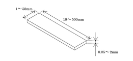
- FIG. It is a figure which shows an example of the turbidity capture
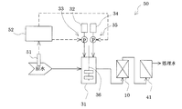
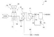
- FIG. It is a schematic system diagram of an example of a water treatment device according to the second embodiment. It is a schematic system diagram of an example of a water treatment device according to the second embodiment. It is a schematic system diagram of an example of a water treatment device according to the second embodiment. It is a schematic system diagram of an example of a water treatment device according to the second embodiment.
- FIG. 1 is a cross-sectional view showing a configuration of a filtration device according to Embodiment 1 of the present invention
- FIG. 2 is an enlarged view of a main part of FIG.
- the filtration device 10 includes a cylindrical filtration tank 11 through which the water to be treated 1 is passed and a filter body 12 that captures turbidity in the water to be treated.
- the filter body 12 includes a core material 13 connected to both ends of the filtration tank 11 in the water flow direction, and a string-like turbidity capturing unit 14.
- a circular plate 16 made of resin or the like provided with a plurality of holes to the extent that water to be treated containing turbidity can freely flow is provided at both ends of the filtration tank 11 in the water flow direction. Both ends of the core material 13 are fixed to the center of the core.
- the turbidity trapping part 14 is provided so that a part of the turbidity trapping part 14 is knitted and fixed to the core member 13 and a so-called loop-like part that is not fixed spreads radially toward the inner wall surface of the filtration tank 11.
- the filter body 12 spreads throughout the filtration tank 11. For this reason, since the turbidity capture
- acquisition part 14 is what made the long rectangle (tape) into the loop shape, and as shown to the enlarged view of the string-like turbidity capture
- a plurality of slits 15 that do not reach are provided. By providing the slit 15 in this way, the trapping effect of turbidity is improved.
- the filter body 12 is filled in the filtration tank 11 so that the porosity of the filtration part when the water to be treated is passed is 50 to 95%, preferably 60 to 90%.
- the porosity is a value obtained from the following formula.
- the filtration part is a region where the suspended matter of the water to be treated is trapped by the filter body 12, that is, the inner wall surface of the filtration tank 11 is the side surface and both ends of the water passage direction of the filter body 12 during water flow are in the thickness direction.
- the part which does not contribute to filtration (the part of the core material 13 in this embodiment) is excluded from the layer in which the turbidity trapping part 14 of the filter body 12 is filled as both ends.
- a filtration part makes the inner wall surface of the filtration tank 11 a side surface, and the turbidity of the filter body 12 makes the water flow direction both ends of the filter body 12 at the time of water flow the both ends of the thickness direction.
- the layer in which the capturing part 14 is filled is said. “The volume of the filtration part—the volume of the turbidity trapping part” is, for example, filled in the filtration tank 11 without the compacting of the filter body 12 during the filtration operation (when the water to be treated is passed) as in this embodiment.
- the volume of the core material 13 is reduced from the amount of the water to be treated which overflows when the filter body 12 is put into the filtration tank 11 filled with the water to be treated. Can be easily obtained.
- both ends of the filter body 12 are being fixed to the water flow direction both ends of the filtration tank 11, respectively, since the filter body 12 has spread over the filtration tank 11 whole at the time of the to-be-processed water flow, A portion obtained by subtracting the portion of the core material 13 from the entire inside of the filtration tank 11 is a filtration portion.
- Porosity (%) [(volume of filtration part ⁇ volume of turbidity trapping part) / volume of filtration part] ⁇ 100
- the water to be treated passes between the string-like turbid traps 14 or between the slits 15 provided in the turbid trap 14.
- the turbidity contained in the treated water is trapped in the string-like turbidity capturing part 14 and the slit 15, and the water to be treated from which the turbidity has been removed is discharged from the filtration tank 11.
- the filter body 12 is filled so that the porosity of the filtration part during water passage is 50 to 95%, water passage is not hindered and turbid trapping is also good.
- treated water industrial water, city water, well water, river water, lake water, factory waste water (particularly biological treated water obtained by biological treatment of waste water from the factory), and flocculant added to these Examples include water subjected to agglomeration treatment.
- the filter body 12 by filling the filter body 12 so that the porosity of the filtration part during water passage is 50 to 95%, water passage is not hindered and turbidity traps are improved. 10 can be suppressed, and for example, clear treated water having a turbidity of 3 or less can be obtained. If the porosity is higher than 95%, the water flow becomes good and it becomes easy to filter at high speed, but the turbidity of the treated water becomes remarkably high, and if it is lower than 50%, the trap of turbidity is good. However, the water flow is insufficient and the filtration device or the membrane separation processing means provided in the latter stage as necessary is clogged, and the differential pressure increase rate is significantly increased.
- the turbidity of the treated water is deteriorated, or the apparatus is blocked.
- the filtration device 10 filled with the filter body 12 so that the porosity is 50 to 95% even if the water to be treated has high speed operation or high turbidity, Clogging can be suppressed and clear treated water can be obtained.
- the porosity is uniform, it is preferable that the turbid trap 14 is filled to the vicinity of both ends of the filtration tank 11 in the water flow direction. It is preferable to fill up to the vicinity of the inner wall surface.
- the volume of a filtration part does not fluctuate
- it is preferably 10% or less.
- size of the filtration tank 11 is a cylinder shape, for example, it can be 100-1000 mm in diameter and 200-1000 mm in height.
- the filter tank 11 is filled with a plurality of filter bodies 11, the turbidity trapping portion 14 of the filter body 12 is enlarged, and the like. What is necessary is just to make it the porosity of the filtration part at the time of water to be 50 to 95%.
- examples of the material of the core material 13 and the turbidity capturing portion 14 include synthetic resins such as polypropylene, polyester, and nylon.
- the core material 13 may have strength by knitting synthetic fibers such as polypropylene, polyester, and nylon in the manufacturing process.
- the filter body 12 which spreads radially by twisting the metal after arranging the turbidity trapping portions 14 uniformly after using the wire made of SUS or a resin-coated metal coated with a resin like a torsion brush as a core material 13. It is good. By improving the strength of the core member 13 in this manner, the core member 13 is not bent, and the end of the filter body 12 can be easily fixed, so that the replacement work of the filter body 12 is facilitated.
- the thickness is 0.05 to 2 mm
- the width is 1 to 50 mm
- the length is (Distance from the core material when water to be treated is passed) It can be about 10 to 500 mm, preferably about 0.3 to 2 mm in thickness, 1 to 20 mm in width, and about 50 to 200 mm in length.
- the tubular filtration tank 11 is used, but it does not have to be tubular and may have a shape that allows water to pass therethrough, that is, a hollow shape, for example, a shape in which a hollow is provided in a prism.
- a hollow shape for example, a shape in which a hollow is provided in a prism.
- the both ends of the core material 13 were fixed to the plate 16, it is not limited to this, For example, you may make it fix only one end of a core material.
- the loop-like turbidity capturing portion 14 is provided so as to protrude from the core material 13, but the present invention is not limited thereto.
- One end of each turbidity trapping part may be fixed to the core material as a trapping part.
- acquisition part 14 was made into square, there is no limitation in particular, For example, circular shape may be sufficient.
- the length of each turbidity trapping part may be the same or different.
- the material of the turbidity capturing unit 14 is one type, but may be two or more types.
- acquisition part may be plural or single, and does not need to provide. And although there may not be the core material 13 and it is good also as the filter body 12 comprised only by a turbidity capture
- FIG. 4 is a schematic system diagram of a water treatment device according to Embodiment 2 of the present invention.
- symbol is attached
- the water treatment device 30 holds a reaction vessel 31 into which water to be treated (raw water) is introduced, and chemicals such as particles made of a cationic polymer that swells in water and does not substantially dissolve in water.
- a chemical introduction means 33 including a pump for introducing a chemical from the chemical tank 32 to the reaction tank 31 and a pump for introducing the inorganic flocculant from the inorganic flocculant tank 34 holding the inorganic flocculant to the reaction tank 31
- Inorganic flocculant introduction means 35 and the filtration apparatus 10 of Embodiment 1 into which water to be treated that has been subjected to agglomeration treatment such as adsorption or coagulation in the reaction tank 31 is introduced.
- water to be treated (raw water) is introduced into the reaction tank 31.
- a chemical such as particles made of a cationic polymer that swells in water held in the chemical tank 32 and does not substantially dissolve in water, or an inorganic flocculant held in the inorganic flocculant tank 34 is added to the chemical introduction means 33 or It is introduced into the reaction tank 31 by the inorganic flocculant introduction means 35 and added to the water to be treated.
- dissolve in water substantially, and the inorganic flocculant were added are stirred by the stirrer 36, and are coagulated.
- the water to be treated that has been subjected to the agglomeration treatment is discharged from the reaction tank 31 and sent to the filtration device 10 to remove turbidity.
- the filtration device 10 filled with the filter body so as to have the predetermined porosity is used, the filtration device 10 can be prevented from being blocked and clear treated water can be obtained. There is an effect.
- the water to be treated includes, for example, water containing a humic acid / fulvic acid organic substance, a biological metabolite such as sugar produced by algae, or a synthetic chemical substance such as a surfactant, specifically, Industrial water, city water, well water, river water, lake water, factory wastewater (particularly, biologically treated water obtained by biologically treating wastewater from a factory) and the like are not limited thereto.
- the humic substance refers to a corrosive substance generated by the decomposition of plants and the like into microorganisms, and includes humic acid, and the water containing the humic substance is derived from humic substance and / or humic substance. It has a soluble COD component, suspended matter and chromaticity component.
- the cationic polymer which swells in water and does not substantially dissolve in water constituting particles composed of a cationic polymer which swells in water added as a flocculant and is not substantially dissolved in water includes, for example, primary amines, It is a copolymer of a cationic monomer having a functional group such as a secondary amine, tertiary amine and their acid salts, and a quaternary ammonium group, and a crosslinking agent monomer so as not to substantially dissolve in water. .
- the cationic monomer examples include dimethylaminoethyl (meth) acrylate acid salt or its quaternary ammonium salt, dimethylaminopropyl (meth) acrylamide acid salt or its quaternary ammonium salt, diallyldimethylammonium chloride, and the like. It is done.
- the cross-linking agent monomer examples include divinyl monomers such as methylene bisacrylamide.
- anionic monomer to be copolymerized examples include (meth) acrylic acid, 2-acrylamido-2-methylpropanesulfonic acid, and alkali metal salts thereof. It is necessary to use a small amount so as not to impair the properties as a conductive polymer.
- Nonionic monomers include (meth) acrylamide, N isopropylacrylamide, N methyl (NN dimethyl) acrylamide, acrylonitrile, styrene, methyl or ethyl (meth) acrylate. Each monomer may be one kind or plural kinds.
- the amount of the cross-linking agent monomer such as divinyl monomer is required to be 0.0001 to 0.1 mol% with respect to the total monomer, and this amount comprises a cationic polymer that swells in water and does not substantially dissolve in water.
- the degree of particle swelling and the particle size in water can be adjusted.
- particles made of a cationic polymer that swells in water and does not substantially dissolve in water for example, Krivata EP (manufactured by Kurita Kogyo) is commercially available.
- an anion exchange resin such as WA20 (manufactured by Mitsubishi Chemical Corporation) may be used as a cationic polymer that swells in water and does not substantially dissolve in water.
- the average particle size of the particles made of a cationic polymer that swells in water and does not substantially dissolve in water is not particularly limited, but the average particle size in a reversed-phase emulsion liquid or a suspension-like dispersion liquid, that is, in water
- the average particle size in the unswelled state is preferably 100 ⁇ m or less, more preferably 0.1 to 10 ⁇ m.
- the form of adding particles composed of a cationic polymer that swells in water and does not substantially dissolve in water to the water to be treated is not particular limitation.
- the particles may be used as they are, or dispersed in water. You may add in the form of an emulsion liquid or a suspension-like dispersion liquid.
- the water to be treated is agglomerated by adding particles made of a cationic polymer that swells in water and does not substantially dissolve in water, that is, the water to be treated swells in water. Then, the turbidity contained in the water to be treated may be adsorbed to the particles by contacting with particles made of a cationic polymer that is substantially insoluble in water.
- particles made of a cationic polymer that swells in two or more kinds of water and does not substantially dissolve in water may be added to the water to be treated. Since the cationic polymer constituting the above particles swells in water and does not substantially dissolve in water, particles made of a cationic polymer that swells in water and does not substantially dissolve in water are also classified as ordinary polymer flocculants. Unlike, it swells in water and does not substantially dissolve in water. “Substantially insoluble in water” means that the degree of water solubility is such that it can exist as particles composed of a cationic polymer in water. Specifically, for example, solubility in water at 30 ° C. Is about 0.1 g / L or less. The degree of swelling of these particles in water is about 10 to 200 times the particle size in water compared to the particle size when not swollen with water.
- the particles made of a cationic polymer that swells in water and does not substantially dissolve in water in the form of a reversed-phase emulsion liquid will be described in detail below, but the present invention is not limited to this form. In addition, it is not a special thing but is a very general reverse phase (W / O) emulsion polymer.
- the inverse emulsion liquid contains a cationic polymer that swells in water and does not substantially dissolve in water, water, a hydrocarbon liquid, and a surfactant.
- the total mass is preferably 40 to 60% by mass.
- hydrocarbon liquids examples include, but are not limited to, isoparaffins such as isohexane, and aliphatic hydrocarbon liquids such as n-hexane, kerosene, and mineral oil.
- the surfactant examples include polyoxyethylene ethers of higher aliphatic alcohols having an HLB (hydrophilic lipophilic balance) of 7 to 10 and 10 to 20 carbon atoms, or higher fatty acids having 10 to 22 carbon atoms.
- a polyoxyethylene ester is mentioned.
- the reversed-phase emulsion liquid is a mixture of a cationic monomer or a crosslinking agent monomer, which is a raw material of a cationic polymer that swells in water and does not substantially dissolve in water, and water, a hydrocarbon liquid, and a surfactant. It can be obtained by polymerization (emulsion polymerization or suspension polymerization), but is not limited to this. For example, after various monomers are solution polymerized, they are pulverized with a homogenizer, and then a dispersant such as a surfactant. It can also be obtained by adding to a hydrocarbon liquid.
- the surface area of the particles is preferably large. Therefore, it is preferable to add the particles in the form of the above-mentioned reversed phase emulsion liquid or suspension-like dispersion liquid to the water to be treated after adding the particles to the water under stirring to swell the particles.
- the amount of particles composed of a cationic polymer that swells in water and does not substantially dissolve in water is 0.2 to 5 mg / L with respect to the water to be treated.
- the content is preferably about 1 to 50% by mass with respect to the contained turbidity.
- the pH of the water to be treated to which particles made of a cationic polymer that swells in water and does not substantially dissolve in water is not particularly limited, but may be a low pH, for example, about pH 5.0 to 7.5. preferable. This is because the cohesiveness is particularly good.
- the inorganic flocculant added to the water to be treated is not particularly limited, and examples thereof include aluminum salts such as sulfate bands and polyaluminum chloride, and iron salts such as ferric chloride and ferrous sulfate. Further, the amount of the inorganic flocculant added is not particularly limited, and may be adjusted according to the properties of the water to be treated, but is generally 0.5 to 10 mg / L in terms of aluminum or iron with respect to the water to be treated. It is.
- PAC polyaluminum chloride
- particles made of a cationic polymer that swells in water and does not substantially dissolve in water and an inorganic flocculant are added. Aggregation is optimal when the pH of the treated water is about pH 5.0 to 7.0.
- the inorganic flocculant may be added before or after the particles composed of a cationic polymer that swells in water and does not substantially dissolve in water, or after the particles are swollen in water and does not substantially dissolve in water. You may add simultaneously with the particle
- FIG. 5 it is good also as the water treatment apparatus 40 which provided the membrane separation process means 41 in the back
- FIG. Examples of the membrane separation treatment include a microfiltration membrane (MF membrane), an ultrafiltration membrane (UF membrane), a nanofiltration membrane (NF membrane), or a reverse osmosis membrane (RO membrane). These membranes may be used alone or in one or more stages. For example, membrane separation treatment that combines various membranes, such as membrane separation treatment with MF membrane or UF membrane, followed by membrane separation treatment with RO membrane. It is good.
- MF membrane microfiltration membrane
- UF membrane ultrafiltration membrane
- NF membrane nanofiltration membrane
- RO membrane reverse osmosis membrane
- industrial water, city water, well water, biologically treated water, etc. which are treated water, include humic acid / fulvic acid organic substances, biological metabolites such as sugar produced by algae, surfactants, etc.
- membrane contaminants such as synthetic chemical substances are included, when membrane separation treatment is performed, there is a problem that membrane contaminants are adsorbed on the membrane surface and membrane separation performance deteriorates.
- particles made of a cationic polymer that swells in water and does not substantially dissolve in water are added before the membrane separation treatment. Therefore, after membrane contaminants adsorb and aggregate on the particles. A membrane separation process is performed.
- the filtration device 10 and the membrane separation processing means 41 are arranged side by side.
- the present invention is not limited to this, and the filtration device 10 and the membrane separation processing means 41 may be integrally stacked vertically. . Thereby, the installation area can be reduced and the number of components can be reduced.
- the light absorbency measurement means 51 which measures the light absorbency of to-be-processed water in the raw
- the amount of particles made of a cationic polymer that swells in water introduced into the reaction tank 31 from the chemical tank 32 and does not substantially dissolve in water is received, and the absorbance data measured by the absorbance measuring means 51 is received.
- the water treatment apparatus 50 may be provided with an addition amount control means 52 for calculating the addition amount of the inorganic flocculant introduced from the inorganic flocculant tank 34 to the reaction tank 31 and controlling the addition amount.
- the addition amount control means 52 performs water treatment on the water to be treated having various absorbances having different water qualities in advance using particles composed of a cationic polymer that swells in water with a jar tester and does not substantially dissolve in water, and an inorganic flocculant.
- the addition amount correction information has a formula for determining the relationship between the absorbance of the water to be treated and the optimum addition amount of particles made of a cationic polymer that swells in water and does not substantially dissolve in water.
- the addition amount control means 52 calculates the optimum addition amount from the absorbance data of the water to be treated (raw water) measured by the absorbance measurement means 51 and this relational expression (addition amount correction information).
- the addition amount of particles composed of a cationic polymer that swells in the introduced water and does not substantially dissolve in water is controlled.
- the addition amount control means 52 preliminarily treats the water to be treated having various absorbances with different water quality using an inorganic flocculant, so that the absorbance of the water to be treated and the optimum addition amount of the inorganic flocculant are determined. Is obtained as addition amount correction information.
- the addition amount control means 52 calculates the optimum addition amount from the absorbance data of the water to be treated (raw water) measured by the absorbance measurement means 51 and this relational expression (addition amount correction information), and the inorganic flocculant introduction means. The amount of the inorganic flocculant introduced from 17 is controlled.
- particles made of a cationic polymer that swells in water and does not substantially dissolve in water first, the absorbance of the water to be treated and the water suitable for treating the water to be treated having the absorbance in advance.
- the addition amount of particles made of a cationic polymer that swells and does not substantially dissolve in water that is, the addition amount that is sufficient to agglomerate soluble organic substances that become turbid and is not excessive.
- the relationship is obtained as addition amount control information.
- the absorbance of the water to be treated is measured, and based on the measurement result of the absorbance and the addition amount correction information, particles of a cationic polymer that swells in water and does not substantially dissolve in water. Control the amount added.
- Soluble organic matter concentration A x [UV absorbance-visible absorbance]
- KMF value 0.45 ⁇ m membrane filter
- a jar test is performed in advance on water to be treated having different water qualities, for example, water to be treated such as industrial water collected on different days, and ultraviolet absorbance and visible absorbance in the following formula (I) are obtained.
- a relationship equation (addition amount control information) between the difference between and the optimum addition concentration of particles made of a cationic polymer that swells in water and does not substantially dissolve in water.
- a to C are constants depending on the water quality such as the concentration of soluble organic matter in the water to be treated
- E260 represents the absorbance at a wavelength of 260 nm
- E660 represents the absorbance at a wavelength of 660 nm.
- the absorbance of the water to be treated is measured, the optimum addition concentration of the particles is obtained from the measurement result of the absorbance and the following formula (I), and the particles of the optimum addition amount are added to the water to be treated.
- the relational expression between the difference between the ultraviolet absorbance and the visible absorbance and the optimum added concentration of the particles is shown as the addition amount control information.
- the threshold control absorbance difference swells in water when less than the predetermined value a 1 substantially the concentration of added particulate cationic polymer which does not dissolve in water and b 1, the absorbance difference is a predetermined value a 1 ⁇ a 2
- the additive concentration of particles is b 2
- the additive concentration of particles is b 3
- the present invention is not limited to this.
- the amount of soluble organic matter that becomes turbidity contained in the water to be treated by controlling the amount of particles made of a cationic polymer that swells in water and does not substantially dissolve in water, an optimum amount is obtained. Since the particles composed of a cationic polymer that swells in an amount of water and does not substantially dissolve in water can be added to the water to be treated, the water to be treated can be treated efficiently. In addition, even when the quality of the water to be treated varies, the optimum amount of particles made of a cationic polymer that swells in water and does not substantially dissolve in water according to the quality of the treated water after variation, Treated water with high clarity can be obtained stably.
- the control of the amount of inorganic flocculant added may be the same as the control of the amount of particles made of a cationic polymer that swells in water and does not substantially dissolve in water.
- the optimal amount of water can be measured. Particles made of a cationic polymer that swells and does not substantially dissolve in water and inorganic flocculants can be added to the water to be treated, so that the water to be treated can be treated efficiently, and the quality of the water to be treated Even in the case of fluctuations, the optimum amount of particles and inorganic flocculants composed of a cationic polymer that swells in water and does not substantially dissolve in water according to the quality of the treated water after fluctuations can be stably added.
- Treated water with high clarity can be obtained.
- a water treatment apparatus having a washing liquid introducing means for introducing a washing liquid and air into the filtration apparatus 10 from a direction opposite to the direction of water flow of the water to be treated may be used.
- the water treatment apparatus has a treated water tank 61 for storing the treated water treated by the membrane separation processing means 41, and the treated water (cleaning liquid) of the treated water tank 61. ) And air are sequentially introduced into the membrane separation processing means 41 and the filtration device 10.
- the treated water that has been subjected to membrane separation after filtration is stored in the treated water tank 61.
- the filter body 12 of the filtration device 10 is a solid caused by particles or an inorganic flocculant made of a cationic polymer that swells in water gradually added as a flocculant by passing water to be treated and does not substantially dissolve in water. Performance deteriorates due to adhesion of contaminants such as objects and turbidity.
- the separation membrane such as the MF membrane of the membrane separation treatment means 41 is caused by particles or inorganic flocculants made of a cationic polymer that swells in water gradually added as flocculant by the membrane separation treatment and does not substantially dissolve in water.
- the valve 63 provided between the reaction tank 31 and the filtration device 10 and the membrane separation processing means 41 and the treated water tank 61 provided at an arbitrary frequency and opened during the membrane separation process.
- the valve 64 is closed to interrupt the membrane separation process.
- another valve 65 connecting the treated water tank 61 and the membrane separation processing means 41 is opened, and a liquid obtained by mixing air with the water to be treated stored in the treated water tank 61 is subjected to membrane separation treatment by a cleaning liquid introducing means 62 such as a pump.
- the separation membrane is back-washed with a cleaning liquid by introducing it into the means 41 and passing it through the separation membrane for about 1 minute, for example.
- the washing liquid that has passed through the membrane separation processing means 41 passes through the filtration device 10, whereby the filter body 12 is backwashed with the washing liquid. Then, the cleaning liquid is discharged as drainage from the filtration device 10 through the valve 66 to the outside of the water treatment device 60. Even if there is no pump or the like for sending the cleaning liquid between the membrane separation processing means 41 and the filtration device 10, the cleaning liquid is introduced into the filtration device 10 by the cleaning liquid introduction means 62 that introduces the cleaning liquid into the membrane separation processing means 41. Can be introduced.
- the filtration part may differ at the time of filtration operation and at the time of backwashing, but it is reverse to the time of filtration.
- the volume change rate of the filtration part during washing is preferably 30% or less, particularly preferably 10% or less.
- a cationic polymer that swells in water and does not substantially dissolve in water and an inorganic flocculant are used as the flocculant, but either one may be used.
- a polymer flocculant etc. may be used and these flocculants may be used together.
- polymer flocculant examples include poly (meth) acrylic acid, a copolymer of (meth) acrylic acid and (meth) acrylamide, and anionic organic polymer flocculants such as alkali metal salts thereof, From nonionic organic polymer flocculants such as poly (meth) acrylamide, cationic monomers such as dimethylaminoethyl (meth) acrylate or quaternary ammonium salts thereof, dimethylaminopropyl (meth) acrylamide or quaternary ammonium salts thereof And a cationic organic polymer flocculant such as a copolymer of a nonionic monomer copolymerizable with these cationic monomers.
- the amount of the organic polymer flocculant added is not particularly limited, and may be adjusted according to the properties of the treated water, but is generally 0.01 to 10 mg / L in solid content with respect to the treated water.
- the flocculant is introduced into the reaction tank 31, but may be introduced before the reaction tank 31.
- a water treatment apparatus further having a purification treatment means for treated water, such as decarboxylation treatment or activated carbon treatment, may be used. And it is good also as a water treatment apparatus which comprises an ultraviolet irradiation means, an ozone treatment means, a biological treatment means, etc. as needed.
- a coagulant if necessary, a coagulant, a bactericidal agent, a deodorant, an antifoaming agent, an anticorrosive agent, and the like may be added.
- each additive may be added to the chemical tank 32 by mixing. it can.
- the filter body used for the filtration apparatus consists of the core material 13 and the string-like turbidity capture
- the core material 13 has a volume of 250 mL, and the thickness of each turbid trap 14 is 0.5 mm, width 2 mm, and length (distance from the core material when the water to be treated is passed) is 100 mm.
- the filter bodies were 30, 40, 50, 60, 70, 80, 90, 95, and 98%.
- the volume change rate of the filtration part was almost 0% when the treated water was passed and other times.
- the size of the filtration tank 11 is 200 mm in diameter and 500 mm in height.
- PAC polyaluminum chloride
- criverter EP with polymer particles for the water to be treated
- Kurita Kogyo's CE colloid equivalent value: 1.3 meq / g (as polymer particles)
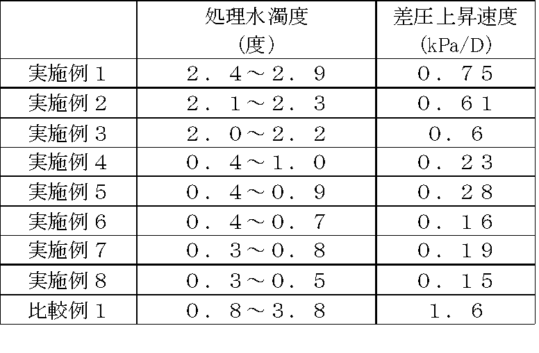
- Table 1 shows the results of measuring the turbidity of the treated water discharged from the filtration device (treated water turbidity) and the differential pressure increase rate (differential pressure increase rate) of the filtration device.
- the turbidity of the treated water was determined by a transmitted light measurement method using a kaolin standard solution, and the differential pressure increase rate of the filtration device was determined by the pressure difference between the inlet and the outlet.
- the differential pressure increase rate and treatment are remarkably higher than those outside the range of 50 to 95%. It was found that water turbidity is low, clear treated water is obtained, and blockage can be suppressed.
- Example 1 As water to be treated (raw water), industrial water with turbidity of 3.4 to 22 degrees, TOC (total organic carbon) of 0.3 to 4.8 mg / L, water temperature: 24.5 to 26.0 ° C. is shown in FIG. Using the apparatus shown (feed amount of raw water: 50 L / h), treatment was performed at LV 200 m / h while periodically changing the water quality. Note that an MF membrane was used as the separation membrane of the membrane separation processing means 41. Table 2 shows the results of measuring the turbidity of treated water discharged from the filtration device and the differential pressure increase rate of the filtration device. As shown in FIG.
- the filtration device 10 has a filter body composed of a core material and a string-like turbid trapping part, and each turbid trapping part 14 has a thickness of 0.5 mm, a width of 2 mm, and a length of 100 mm.
- the porosity of the filtration part at the time of water flow is 85%. Only one end of the core material 13 of the filter body 12 is fixed to the upstream plate 16 in the water flow direction. Although one end of the core material 13 is not fixed, since one end is fixed to the upstream plate 16, the filter medium spreads substantially uniformly throughout the filtration tank when the treated water flows.
- polyaluminum chloride (PAC: 10% by weight as Al 2 O 3 ) was added as a flocculant so as to be 30 mg / L with respect to the water to be treated.
- Example 2 The same operation as in Example 1 was performed except that 2 to 5 slits were made in addition to the portion fixed to the core of each loop-shaped turbidity trapping portion.
- Example 3 The same operation as in Example 2 was performed except that both ends of the core member 13 of the filter body 12 were fixed to the upstream and downstream plates 16 in the water flow direction, respectively.
- Example 4 The same operation as in Example 3 was performed except that 1.4 mg / L of Klibata EP was added to the water to be treated instead of PAC.
- Example 5 The same operation as in Example 3 was carried out except that 0.7 mg / L of Krivata EP was used in combination with the water to be treated.
- Example 6 The same operation as in Example 5 was performed except that the absorbance of the raw water was measured and the addition concentrations of PAC and Krivata EP were controlled based on the absorbance measurement results.
- Example 7 The same operation as in Example 5 was performed except that the turbidity of the raw water was measured and the addition concentrations of PAC and Krivata EP were controlled based on the measurement result of the absorbance.
- Example 8 The same operations as in Example 5 were performed except that the absorbance and turbidity of the raw water were measured and the addition concentrations of PAC and Krivata EP were controlled based on the measurement results of the absorbance and turbidity.
- Example 1 The same operation as in Example 8 was performed except that a sand filtration device was used instead of the filtration device.
- Example 2 As shown in Table 2, in Examples 1 to 8, it was found that the treated water turbidity and the differential pressure increase rate were low, clear treated water was obtained, and the filtration device was not clogged.
- Example 1 When explaining each Example in detail, compared with Comparative Example 1, in Example 1, the treated water turbidity was comparable, but the differential pressure increase rate was slow. Moreover, in Example 2 which provided the slit in the filter body, the treated water turbidity dropped and the differential pressure increase rate was slower than Example 1. And in Example 3 which fixed the both ends of the filter body to the filtration tank, the to-be-processed water turbidity at the time of high turbidity fell rather than Example 2.
- Example 4 in which particles made of a cationic polymer that swells in water and does not substantially dissolve in water are used as the flocculant, flocs become coarse, and the treated water turbidity is lower than that in Example 3 and the differential pressure increase rate.
- Example 5 in which particles composed of a cationic polymer that swells in water and does not substantially dissolve in water and PAC are used in combination, the treated water turbidity is lower than that in Example 3, and the differential pressure increase rate is also slower.
- Example 6 in which the addition amount of the flocculant was controlled based on the absorbance measurement result and in Example 7 in which the addition amount of the flocculant was controlled based on the turbidity measurement result, the treated water turbidity was higher than in Example 5. Decreased and the speed of differential pressure increase slowed. Moreover, in Example 8 which controlled the addition amount of the flocculant based on the absorbance measurement result and the turbidity measurement result, the treated water turbidity was lowered and the differential pressure increase rate was also slower than in Examples 6 and 7.
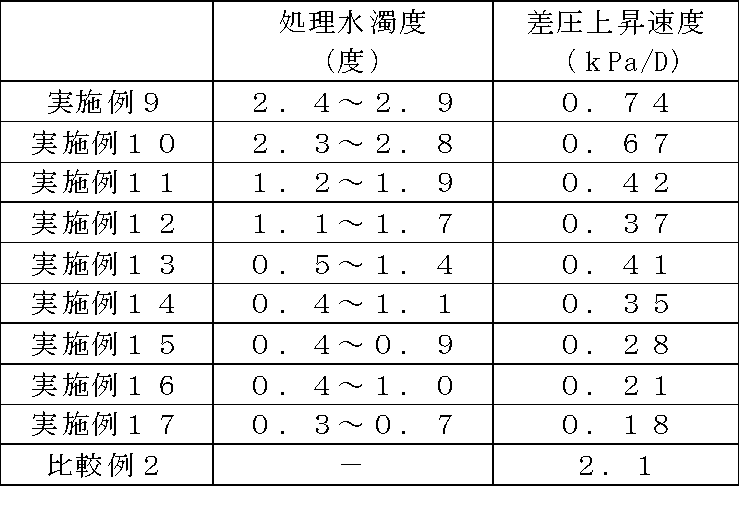
- Example 9 As the water to be treated (raw water), industrial water having a turbidity of 3.2 to 29 degrees, a TOC (total organic carbon) of 0.4 to 5 mg / L, and a water temperature of 24.5 to 26.1 ° C. was used. The same operation as Example 1 was performed except having provided the process of backwashing the membrane separation processing means and the filtration device using the treated water discharged from the membrane separation processing means. In addition, the turbidity of the treated water discharged from the filtration device and the differential pressure increase rate of the MF membrane were determined. The turbidity of the treated water was determined by a transmitted light measurement method using a kaolin standard solution, and the differential pressure increase rate of the MF membrane was determined by the pressure difference between the inlet and the outlet. The results are shown in Table 3.
- Example 10 The same operation as in Example 9 was performed except that the treated water discharged from the membrane separation processing means having the MF membrane was mixed with air.
- Example 11 The same operation as in Example 10 was performed except that 2 to 5 slits were made in addition to the portion fixed to the core of the loop-shaped turbidity trapping portion.
- Example 12 The same operation as in Example 10 was performed except that both ends of the core material 13 of the filter body 12 were fixed to the upstream and downstream plates 16 in the water flow direction, respectively. In addition, since both ends of the core material 13 are fixed by the plate 16, the volume change rate of the filtration part was almost 0% when the treated water was passed and other times such as backwashing.
- Example 13 The same operation as in Example 10 was performed except that 1.4 mg / L of Krivata EP was added to the water to be treated instead of PAC.
- Example 14 The same operation as in Example 10 was carried out except that 0.7 mg / L of Krivata EP was used in combination with the water to be treated.
- Example 15 The same operation as in Example 14 was performed except that the absorbance of the raw water was measured and the addition concentrations of PAC and Krivata EP were controlled based on the absorbance measurement result.
- Example 16 The same operation as in Example 14 was performed except that the turbidity of the raw water was measured and the addition concentration of PAC and Krivata EP was controlled based on the measurement result of the turbidity.
- Example 17 The same operations as in Example 14 were performed except that the absorbance and turbidity of the raw water were measured and the addition concentrations of PAC and Krivata EP were controlled based on the measurement results of the absorbance and turbidity.
- Example 18 The same operation as in Example 17 was performed except that the water treatment apparatus provided with the RO membrane apparatus was provided after the membrane separation treatment means using the MF membrane.
- the TOC concentration of RO membrane permeated water was determined by a wet oxidation-infrared absorption method. The results are shown in Table 4.
- Example 19 Example 18 except that instead of the RO membrane device, a water treatment device provided with a regenerative ion exchange resin device was used, and the TOC concentration of permeate of the regenerative ion exchange resin device was determined by a wet oxidation-infrared absorption method. The same operation was performed.
- Example 2 The same operation as in Example 18 was performed except that the filtration device was not used.
- Example 9 the treated water turbidity or TOC concentration, the MF membrane differential pressure increase rate was low, clear treated water was obtained, and the MF membrane was clogged. There wasn't. In addition, the filtration device was not blocked. The details of each example will be described.
- Example 9 the turbidity of the treated water was low, and the differential pressure increase rate was slower than that of Comparative Example 2.
- Example 10 in which air was mixed and backwashed, the differential pressure increase rate was slower than in Example 9.
- Example 11 in which the filter was provided with slits, the treated water turbidity was lower than in Example 10, and the differential pressure increase rate was slower.
- Example 12 which fixed the both ends of the filter body to the filtration tank, the to-be-processed water turbidity at the time of high turbidity fell rather than Example 10.
- Example 13 in which particles made of a cationic polymer that swells in water and does not substantially dissolve in water are used as the flocculant, flocs become coarse, and the treated water turbidity is lower than in Example 10 and the rate of differential pressure increase. was also late.
- Example 14 in which particles composed of a cationic polymer that swells in water and does not substantially dissolve in water and PAC are used in combination, the turbidity of the treated water is lowered and the rate of increase in the differential pressure is also slower than in Example 13.
- Example 15 in which the addition amount of the flocculant was controlled based on the absorbance measurement result and in Example 16 in which the addition amount of the flocculant was controlled based on the turbidity measurement result, the treated water turbidity was higher than in Example 14. Decreased and the speed of differential pressure increase slowed. Further, in Example 17 in which the addition amount of the flocculant was controlled based on the absorbance measurement result and the turbidity measurement result, the treated water turbidity was lowered and the differential pressure increase rate was also slower than in Examples 15 and 16. In Example 18, the TOC concentration of the RO membrane permeated water was lower than that in Example 19.
Landscapes
- Chemical & Material Sciences (AREA)
- Life Sciences & Earth Sciences (AREA)
- Hydrology & Water Resources (AREA)
- Engineering & Computer Science (AREA)
- Environmental & Geological Engineering (AREA)
- Water Supply & Treatment (AREA)
- Organic Chemistry (AREA)
- Chemical Kinetics & Catalysis (AREA)
- Separation Of Suspended Particles By Flocculating Agents (AREA)
- Separation Using Semi-Permeable Membranes (AREA)
Abstract
Description
(実施形態1)
図1は、本発明の実施形態1に係るろ過装置の構成を示す断面図であり、図2は、図1の要部拡大図である。
空隙率(%)=[(ろ過部の体積-濁質捕捉部の体積)/ろ過部の体積]×100
図4は、本発明の実施形態2に係る水処理装置の概略系統図である。なお、実施形態1と同じ部材には同じ符号を付し、重複する説明は省略してある。
=A×(E260-E660)B+C (I)
被処理水(原水)として、濁度20度の工業用水を図4に示す装置を用いて、LV200m/hで1週間処理した。なお、ろ過装置に用いたろ過体は、図1に示すように芯材13及び紐状の濁質捕捉部14からなり、ろ過槽11の通水方向両端のプレート16にそれぞれ両端が固定されている。そして、芯材13は体積250mLで、各濁質捕捉部14の厚さは、0.5mm、幅2mm、長さ(被処理水を通水した際の芯材からの距離)100mmとなるようループ状に芯材に編みこんだものであり、濁質捕捉部14の編込み密度を変化させて、通水時のろ過部(ろ過槽11内部の体積から芯材13の体積を引いたもの)の空隙率が、30、40、50、60、70、80、90、95、98%のろ過体を作製し、各ろ過体を用いて水処理した。なお、芯材は両端で固定しているため、被処理水通水時とその他のときとではろ過部の体積変化率はほぼ0%であった。また、ろ過槽11の大きさは、直径200mm、高さ500mmである。また、凝集剤として、被処理水に対して30mg/Lのポリ塩化アルミニウム(PAC:10重量% as Al2O3)及び被処理水に対してポリマー粒子として0.7mg/LのクリバータEP(栗田工業製、CE(コロイド当量値):1.3meq/g(asポリマー粒子))を添加した。ろ過装置から排出された処理水の濁度(処理水濁度)及びろ過装置の差圧上昇速度(差圧上昇速度)を測定した結果を表1に示す。なお、処理水の濁度はカオリン標準液を用いた透過光測定方法により求め、ろ過装置の差圧上昇速度は入口と出口の圧力差で求めた。

被処理水(原水)として、濁度3.4~22度、TOC(全有機炭素)0.3~4.8mg/L、水温:24.5~26.0℃の工業用水を図5に示す装置(原水の供給水量:50L/h)を用いて、定期的に水質を変動させながら、LV200m/hで処理した。なお、膜分離処理手段41の分離膜として、MF膜を用いた。ろ過装置から排出された処理水の濁度及びろ過装置の差圧上昇速度を測定した結果を表2に示す。なお、ろ過装置10は図1に示すように芯材及び紐状の濁質捕捉部からなるろ過体を有し、各濁質捕捉部14の厚さは0.5mm、幅2mm、長さ100mmで、通水時のろ過部(ろ過槽11内部の体積から芯材13の体積を引いたもの)の空隙率は85%である。そして、ろ過体12の芯材13の一端のみが、通水方向の上流側のプレート16に固定されている。なお、芯材13の一端は固定されていないが、一端が上流側のプレート16に固定されているため、処理水の通水時にろ過体はろ過槽全体に略均一に広がっていた。また、凝集剤としてポリ塩化アルミニウム(PAC:10重量%as Al2O3)を被処理水に対して、30mg/Lとなるように添加した。
ループ形状の各濁質捕捉部の芯材に固定された箇所以外に2~5本のスリットを入れた以外は、実施例1と同様の操作を行った。
ろ過体12の芯材13の両端をそれぞれ通水方向の上流側及び下流側のプレート16に固定するようにした以外は実施例2と同様の操作を行った。
PACの代わりに、クリバータEPを被処理水に対して1.4mg/L添加した以外は、実施例3と同様の操作を行った。
被処理水に対して0.7mg/LのクリバータEPを併用した以外は実施例3と同様の操作を行った。
原水の吸光度を測定し、該吸光度の測定結果に基づいてPAC及びクリバータEPの添加濃度を制御した以外は、実施例5と同様の操作を行った。
原水の濁度を測定し、該吸光度の測定結果に基づいてPAC及びクリバータEPの添加濃度を制御した以外は、実施例5と同様の操作を行った。
原水の吸光度及び濁度を測定し、該吸光度及び濁度の測定結果に基づいてPAC及びクリバータEPの添加濃度を制御した以外は、実施例5と同様の操作を行った。
ろ過装置の代わりに、砂ろ過装置を用いた以外は、実施例8と同様の操作を行った。
被処理水(原水)として、濁度3.2~29度、TOC(全有機炭素)0.4~5mg/L、水温:24.5~26.1℃の工業用水を用い、MF膜を有する膜分離処理手段から排出された処理水を用いて膜分離処理手段及びろ過装置を逆洗する工程を設けた以外は実施例1と同様の操作を行った。なお、ろ過装置から排出された処理水の濁度及びMF膜の差圧上昇速度を求めた。処理水の濁度はカオリン標準液を用いた透過光測定方法により求め、MF膜の差圧上昇速度は入口と出口の圧力差で求めた。結果を表3に示す。
MF膜を有する膜分離処理手段から排出された処理水に空気を混合したものを用いた以外は、実施例9と同様の操作を行った。
ループ形状の各濁質捕捉部の芯材に固定された箇所以外に2~5本のスリットを入れた以外は、実施例10と同様の操作を行った。
ろ過体12の芯材13の両端をそれぞれ通水方向の上流側及び下流側プレート16に固定するようにした以外は実施例10と同様の操作を行った。なお、芯材13の両端はプレート16で固定されているため、被処理水通水時と逆洗時などのその他のときとではろ過部の体積変化率はほぼ0%であった。
PACの代わりに、クリバータEPを被処理水に対して1.4mg/L添加した以外は、実施例10と同様の操作を行った。
被処理水に対して0.7mg/LのクリバータEPを併用した以外は実施例10と同様の操作を行った。
原水の吸光度を測定し、該吸光度の測定結果に基づいてPAC及びクリバータEPの添加濃度を制御した以外は、実施例14と同様の操作を行った。
原水の濁度を測定し、該濁度の測定結果に基づいてPAC及びクリバータEPの添加濃度を制御した以外は、実施例14と同様の操作を行った。
原水の吸光度及び濁度を測定し、該吸光度及び濁度の測定結果に基づいてPAC及びクリバータEPの添加濃度を制御した以外は、実施例14と同様の操作を行った。
MF膜による膜分離処理手段の後段で、RO膜装置を設けた水処理装置とした以外は、実施例17と同様の操作を行った。RO膜透過水のTOC濃度を湿式酸化-赤外吸収法で求めた。結果を表4に示す。
RO膜装置のかわりに、再生型イオン交換樹脂装置を設けた水処理装置とし、再生型イオン交換樹脂装置透過水のTOC濃度を湿式酸化-赤外吸収法で求めた以外は、実施例18と同様の操作を行った。
ろ過装置を用いなかった以外は実施例18と同様の操作を行った。

Claims (10)
- 紐状の濁質捕捉部を有し通水される被処理水中の濁質を捕捉するろ過体を、通水時のろ過部の空隙率が50~95%となるようにろ過槽に充填したものであることを特徴とするろ過装置。
- 前記ろ過体は、前記ろ過槽の通水方向の両端に接続される芯材を有し、前記紐状の濁質捕捉部は一部が前記芯材に固定されると共に前記ろ過槽の内壁面に向かって広がるように設けられていることを特徴とする請求項1に記載のろ過装置。
- 前記紐状の濁質捕捉部に、スリットが設けられていることを特徴とする請求項1又は2に記載のろ過装置。
- 被処理水が導入される反応槽と、凝集剤を前記反応槽又は反応槽の前段で導入して被処理水に前記凝集剤を添加する凝集剤導入手段と、前記反応槽の後段に設けられ前記反応槽で凝集処理した被処理水が導入される請求項1~3の何れかに記載するろ過装置とを具備することを特徴とする水処理装置。
- 前記ろ過装置の後段に、被処理水を膜分離処理する膜分離処理手段を有することを特徴とする請求項4に記載の水処理装置。
- 前記凝集剤が、無機凝集剤及び水中で膨潤し実質的に水に溶解しないカチオン性ポリマーからなる粒子の少なくとも一種であることを特徴とする請求項4又は5に記載の水処理装置。
- 前記凝集剤導入手段の前段に設けられ被処理水の吸光度を測定する吸光度測定手段と、前記吸光度測定手段で測定された吸光度に基づいて前記凝集剤の被処理水への添加量を制御する添加量制御手段とを具備することを特徴とする請求項4~6の何れかに記載の水処理装置。
- 前記吸光度が、200~400nmの紫外部及び500~700nmの可視部をそれぞれ1波長以上で測定した値であることを特徴とする請求項7に記載の水処理装置。
- 前記凝集剤導入手段の前段に設けられ被処理水の濁度を測定する濁度測定手段と、前記濁度測定手段で測定された濁度に基づいて前記凝集剤の被処理水への添加量を制御する第2添加量制御手段とを具備することを特徴とする請求項4~8の何れかに記載の水処理装置。
- 任意の頻度で、洗浄液及び空気を前記ろ過装置に導入する洗浄液導入手段をさらに有することを特徴とする請求項4~9の何れかに記載の水処理装置。
Priority Applications (4)
| Application Number | Priority Date | Filing Date | Title |
|---|---|---|---|
| JP2010536757A JP5672447B2 (ja) | 2008-11-04 | 2009-10-30 | ろ過装置及び水処理装置 |
| US13/127,166 US20110203977A1 (en) | 2008-11-04 | 2009-10-30 | Filtration apparatus and water treatment apparatus |
| KR1020117010939A KR101282985B1 (ko) | 2008-11-04 | 2009-10-30 | 여과 장치 및 수처리 장치 |
| CN200980143671.0A CN102202754B (zh) | 2008-11-04 | 2009-10-30 | 过滤装置及水处理装置 |
Applications Claiming Priority (2)
| Application Number | Priority Date | Filing Date | Title |
|---|---|---|---|
| JP2008283579 | 2008-11-04 | ||
| JP2008-283579 | 2008-11-04 |
Publications (1)
| Publication Number | Publication Date |
|---|---|
| WO2010053051A1 true WO2010053051A1 (ja) | 2010-05-14 |
Family
ID=42152861
Family Applications (1)
| Application Number | Title | Priority Date | Filing Date |
|---|---|---|---|
| PCT/JP2009/068659 Ceased WO2010053051A1 (ja) | 2008-11-04 | 2009-10-30 | ろ過装置及び水処理装置 |
Country Status (6)
| Country | Link |
|---|---|
| US (1) | US20110203977A1 (ja) |
| JP (1) | JP5672447B2 (ja) |
| KR (1) | KR101282985B1 (ja) |
| CN (1) | CN102202754B (ja) |
| MY (1) | MY150813A (ja) |
| WO (1) | WO2010053051A1 (ja) |
Cited By (3)
| Publication number | Priority date | Publication date | Assignee | Title |
|---|---|---|---|---|
| JP2012196628A (ja) * | 2011-03-22 | 2012-10-18 | Swing Corp | 浄水処理方法及び浄水処理装置 |
| JP5843071B2 (ja) * | 2010-03-30 | 2016-01-13 | 栗田工業株式会社 | 水処理装置 |
| WO2018168021A1 (ja) * | 2017-03-13 | 2018-09-20 | 栗田工業株式会社 | 凝集剤注入制御方法、制御装置および水処理システム |
Families Citing this family (3)
| Publication number | Priority date | Publication date | Assignee | Title |
|---|---|---|---|---|
| FI20165758A (fi) * | 2016-10-07 | 2018-04-08 | Kemira Oyj | Menetelmä ja järjestelmä hydrofobisten olosuhteiden ja likaantumisen kontrolloimiseksi vesi-intensiivissä prosesseissa |
| NO343524B1 (no) * | 2017-02-09 | 2019-04-01 | M Vest Water As | Fremgangsmåte for fjerning av uønsket organisk og uorganisk forurensing i væsker |
| US20220097007A1 (en) * | 2019-01-28 | 2022-03-31 | Kurita Water Industries Ltd. | Chemical dosing control method |
Citations (12)
| Publication number | Priority date | Publication date | Assignee | Title |
|---|---|---|---|---|
| JPS6411616U (ja) * | 1987-07-10 | 1989-01-20 | ||
| JPH04244205A (ja) * | 1991-01-29 | 1992-09-01 | Shinko Pantec Co Ltd | 高速濾過装置 |
| JPH10192605A (ja) * | 1997-01-09 | 1998-07-28 | Toshiba Corp | ろ床ろ過器およびこのろ過器を設置した発電プラント |
| JPH11262602A (ja) * | 1998-03-18 | 1999-09-28 | Japan Organo Co Ltd | 長繊維束を用いたろ過塔 |
| JP2002045612A (ja) * | 2000-08-01 | 2002-02-12 | Tookemi:Kk | 濾過装置 |
| JP2003024715A (ja) * | 2001-07-19 | 2003-01-28 | Nippon Rensui Co Ltd | 濾過装置 |
| JP2003035959A (ja) * | 2001-07-24 | 2003-02-07 | Mitsubishi Paper Mills Ltd | ネガ型感光性平版印刷版の現像廃液の処理方法 |
| JP2003265907A (ja) * | 2002-03-18 | 2003-09-24 | Japan Organo Co Ltd | 長繊維ろ過装置 |
| JP2004083899A (ja) * | 2002-08-06 | 2004-03-18 | Is:Kk | ポリエチレンテレフタレート解重合溶液からの微粒子の除去方法及びこれに用いた濾材の再生方法 |
| JP2004089766A (ja) * | 2002-08-29 | 2004-03-25 | Ebara Corp | 懸濁水の上向流ろ過方法及び装置 |
| JP2007185647A (ja) * | 2005-08-24 | 2007-07-26 | Tokuyama Corp | シリコン粉含有排水の処理方法 |
| JP2008173534A (ja) * | 2007-01-16 | 2008-07-31 | Toray Ind Inc | 水処理方法および水処理装置 |
Family Cites Families (9)
| Publication number | Priority date | Publication date | Assignee | Title |
|---|---|---|---|---|
| CH556800A (de) * | 1973-07-13 | 1974-12-13 | Swissair | Verfahren und anlage zur aufbereitung von abwasser zu brauchwasser. |
| SE7710010L (sv) * | 1976-10-11 | 1978-04-12 | Mueller Hans | Forfarande och anordning for filtrering av vetskor och gaser samt anvendning av forfarandet resp anordningen |
| JPS5931355Y2 (ja) * | 1981-11-19 | 1984-09-05 | 日本産業機械株式会社 | 浸漬「ろ」床装置 |
| JPS6411616A (en) * | 1987-07-06 | 1989-01-17 | Yuji Fukuda | Filter for use in channel |
| US5420432A (en) * | 1991-03-19 | 1995-05-30 | Welsh Water Enterprises Limited | Organic pollutant monitor |
| US5643449A (en) * | 1991-05-15 | 1997-07-01 | Brinkley; Herman E. | Apparatus for lifting oil-based liquid |
| US6200619B1 (en) * | 1996-06-17 | 2001-03-13 | Fuji Oil Co., Ltd. | Preserving agent and preserving method |
| US7632410B2 (en) * | 2003-08-21 | 2009-12-15 | Christopher Heiss | Universal water purification system |
| JP2008246372A (ja) * | 2007-03-30 | 2008-10-16 | Kurita Water Ind Ltd | 排水処理方法 |
-
2009
- 2009-10-30 KR KR1020117010939A patent/KR101282985B1/ko not_active Expired - Fee Related
- 2009-10-30 CN CN200980143671.0A patent/CN102202754B/zh not_active Expired - Fee Related
- 2009-10-30 MY MYPI20111869 patent/MY150813A/en unknown
- 2009-10-30 US US13/127,166 patent/US20110203977A1/en not_active Abandoned
- 2009-10-30 WO PCT/JP2009/068659 patent/WO2010053051A1/ja not_active Ceased
- 2009-10-30 JP JP2010536757A patent/JP5672447B2/ja active Active
Patent Citations (12)
| Publication number | Priority date | Publication date | Assignee | Title |
|---|---|---|---|---|
| JPS6411616U (ja) * | 1987-07-10 | 1989-01-20 | ||
| JPH04244205A (ja) * | 1991-01-29 | 1992-09-01 | Shinko Pantec Co Ltd | 高速濾過装置 |
| JPH10192605A (ja) * | 1997-01-09 | 1998-07-28 | Toshiba Corp | ろ床ろ過器およびこのろ過器を設置した発電プラント |
| JPH11262602A (ja) * | 1998-03-18 | 1999-09-28 | Japan Organo Co Ltd | 長繊維束を用いたろ過塔 |
| JP2002045612A (ja) * | 2000-08-01 | 2002-02-12 | Tookemi:Kk | 濾過装置 |
| JP2003024715A (ja) * | 2001-07-19 | 2003-01-28 | Nippon Rensui Co Ltd | 濾過装置 |
| JP2003035959A (ja) * | 2001-07-24 | 2003-02-07 | Mitsubishi Paper Mills Ltd | ネガ型感光性平版印刷版の現像廃液の処理方法 |
| JP2003265907A (ja) * | 2002-03-18 | 2003-09-24 | Japan Organo Co Ltd | 長繊維ろ過装置 |
| JP2004083899A (ja) * | 2002-08-06 | 2004-03-18 | Is:Kk | ポリエチレンテレフタレート解重合溶液からの微粒子の除去方法及びこれに用いた濾材の再生方法 |
| JP2004089766A (ja) * | 2002-08-29 | 2004-03-25 | Ebara Corp | 懸濁水の上向流ろ過方法及び装置 |
| JP2007185647A (ja) * | 2005-08-24 | 2007-07-26 | Tokuyama Corp | シリコン粉含有排水の処理方法 |
| JP2008173534A (ja) * | 2007-01-16 | 2008-07-31 | Toray Ind Inc | 水処理方法および水処理装置 |
Cited By (4)
| Publication number | Priority date | Publication date | Assignee | Title |
|---|---|---|---|---|
| JP5843071B2 (ja) * | 2010-03-30 | 2016-01-13 | 栗田工業株式会社 | 水処理装置 |
| JP2012196628A (ja) * | 2011-03-22 | 2012-10-18 | Swing Corp | 浄水処理方法及び浄水処理装置 |
| WO2018168021A1 (ja) * | 2017-03-13 | 2018-09-20 | 栗田工業株式会社 | 凝集剤注入制御方法、制御装置および水処理システム |
| JP2018149495A (ja) * | 2017-03-13 | 2018-09-27 | 栗田工業株式会社 | 凝集剤注入制御方法、制御装置および水処理システム |
Also Published As
| Publication number | Publication date |
|---|---|
| KR101282985B1 (ko) | 2013-07-05 |
| JPWO2010053051A1 (ja) | 2012-04-05 |
| CN102202754A (zh) | 2011-09-28 |
| MY150813A (en) | 2014-02-28 |
| JP5672447B2 (ja) | 2015-02-18 |
| US20110203977A1 (en) | 2011-08-25 |
| KR20110084937A (ko) | 2011-07-26 |
| CN102202754B (zh) | 2014-10-01 |
Similar Documents
| Publication | Publication Date | Title |
|---|---|---|
| CN103768947B (zh) | 膜分离方法 | |
| JP5218731B2 (ja) | 水処理方法及び水処理装置 | |
| JP5561473B2 (ja) | 濾過装置及び水処理装置 | |
| JP5843071B2 (ja) | 水処理装置 | |
| JP5672447B2 (ja) | ろ過装置及び水処理装置 | |
| JP5282864B2 (ja) | 膜分離方法及び膜分離装置 | |
| JP3409322B2 (ja) | 純水製造方法 | |
| JP2011206750A (ja) | 水処理方法及び水処理装置 | |
| JP5348369B2 (ja) | 水処理方法 | |
| JP2012206066A (ja) | 好気性生物処理水からの水の回収方法 | |
| JP2010179247A (ja) | ろ過装置及び水処理装置 | |
| JP2019188338A (ja) | 水処理方法及び水処理装置 | |
| CN112739448B (zh) | 膜用水处理药品及膜处理方法 | |
| Johir et al. | Deep bed filter as pre-treatment to stormwater | |
| JP2016093789A (ja) | 水処理方法及び水処理システム | |
| JP2021186745A (ja) | 凝集膜ろ過システムおよび凝集膜ろ過方法 | |
| JP2005111404A (ja) | 凝集濾過方法 | |
| CA2817377C (en) | Use of water soluble block copolymers to improve membrane bioreactor systems in water treatment | |
| JP2020069448A (ja) | 浄水処理方法及び浄水処理装置 | |
| JP2018075544A (ja) | 水処理装置および水処理方法 | |
| JP2009240905A (ja) | 膜分離方法及び膜分離装置 | |
| JP2016093781A (ja) | 水処理方法及び水処理システム |
Legal Events
| Date | Code | Title | Description |
|---|---|---|---|
| WWE | Wipo information: entry into national phase |
Ref document number: 200980143671.0 Country of ref document: CN |
|
| 121 | Ep: the epo has been informed by wipo that ep was designated in this application |
Ref document number: 09824751 Country of ref document: EP Kind code of ref document: A1 |
|
| ENP | Entry into the national phase |
Ref document number: 2010536757 Country of ref document: JP Kind code of ref document: A |
|
| WWE | Wipo information: entry into national phase |
Ref document number: 13127166 Country of ref document: US |
|
| NENP | Non-entry into the national phase |
Ref country code: DE |
|
| ENP | Entry into the national phase |
Ref document number: 20117010939 Country of ref document: KR Kind code of ref document: A |
|
| WWE | Wipo information: entry into national phase |
Ref document number: 1147/MUMNP/2011 Country of ref document: IN |
|
| 122 | Ep: pct application non-entry in european phase |
Ref document number: 09824751 Country of ref document: EP Kind code of ref document: A1 |