WO2010052922A1 - インバータ一体型電動圧縮機 - Google Patents
インバータ一体型電動圧縮機 Download PDFInfo
- Publication number
- WO2010052922A1 WO2010052922A1 PCT/JP2009/005921 JP2009005921W WO2010052922A1 WO 2010052922 A1 WO2010052922 A1 WO 2010052922A1 JP 2009005921 W JP2009005921 W JP 2009005921W WO 2010052922 A1 WO2010052922 A1 WO 2010052922A1
- Authority
- WO
- WIPO (PCT)
- Prior art keywords
- inverter
- motor drive
- drive circuit
- electric compressor
- integrated electric
- Prior art date
- Legal status (The legal status is an assumption and is not a legal conclusion. Google has not performed a legal analysis and makes no representation as to the accuracy of the status listed.)
- Ceased
Links
Images



Classifications
-
- F—MECHANICAL ENGINEERING; LIGHTING; HEATING; WEAPONS; BLASTING
- F04—POSITIVE - DISPLACEMENT MACHINES FOR LIQUIDS; PUMPS FOR LIQUIDS OR ELASTIC FLUIDS
- F04B—POSITIVE-DISPLACEMENT MACHINES FOR LIQUIDS; PUMPS
- F04B39/00—Component parts, details, or accessories, of pumps or pumping systems specially adapted for elastic fluids, not otherwise provided for in, or of interest apart from, groups F04B25/00 - F04B37/00
- F04B39/12—Casings; Cylinders; Cylinder heads; Fluid connections
- F04B39/121—Casings
-
- F—MECHANICAL ENGINEERING; LIGHTING; HEATING; WEAPONS; BLASTING
- F04—POSITIVE - DISPLACEMENT MACHINES FOR LIQUIDS; PUMPS FOR LIQUIDS OR ELASTIC FLUIDS
- F04C—ROTARY-PISTON, OR OSCILLATING-PISTON, POSITIVE-DISPLACEMENT MACHINES FOR LIQUIDS; ROTARY-PISTON, OR OSCILLATING-PISTON, POSITIVE-DISPLACEMENT PUMPS
- F04C23/00—Combinations of two or more pumps, each being of rotary-piston or oscillating-piston type, specially adapted for elastic fluids; Pumping installations specially adapted for elastic fluids; Multi-stage pumps specially adapted for elastic fluids
- F04C23/008—Hermetic pumps
-
- F—MECHANICAL ENGINEERING; LIGHTING; HEATING; WEAPONS; BLASTING
- F04—POSITIVE - DISPLACEMENT MACHINES FOR LIQUIDS; PUMPS FOR LIQUIDS OR ELASTIC FLUIDS
- F04C—ROTARY-PISTON, OR OSCILLATING-PISTON, POSITIVE-DISPLACEMENT MACHINES FOR LIQUIDS; ROTARY-PISTON, OR OSCILLATING-PISTON, POSITIVE-DISPLACEMENT PUMPS
- F04C23/00—Combinations of two or more pumps, each being of rotary-piston or oscillating-piston type, specially adapted for elastic fluids; Pumping installations specially adapted for elastic fluids; Multi-stage pumps specially adapted for elastic fluids
- F04C23/02—Pumps characterised by combination with, or adaptation to, specific driving engines or motors
-
- F—MECHANICAL ENGINEERING; LIGHTING; HEATING; WEAPONS; BLASTING
- F04—POSITIVE - DISPLACEMENT MACHINES FOR LIQUIDS; PUMPS FOR LIQUIDS OR ELASTIC FLUIDS
- F04C—ROTARY-PISTON, OR OSCILLATING-PISTON, POSITIVE-DISPLACEMENT MACHINES FOR LIQUIDS; ROTARY-PISTON, OR OSCILLATING-PISTON, POSITIVE-DISPLACEMENT PUMPS
- F04C29/00—Component parts, details or accessories of pumps or pumping installations, not provided for in groups F04C18/00 - F04C28/00
- F04C29/0042—Driving elements, brakes, couplings, transmissions specially adapted for pumps
- F04C29/0085—Prime movers
-
- H—ELECTRICITY
- H02—GENERATION; CONVERSION OR DISTRIBUTION OF ELECTRIC POWER
- H02K—DYNAMO-ELECTRIC MACHINES
- H02K11/00—Structural association of dynamo-electric machines with electric components or with devices for shielding, monitoring or protection
- H02K11/01—Structural association of dynamo-electric machines with electric components or with devices for shielding, monitoring or protection for shielding from electromagnetic fields, i.e. structural association with shields
- H02K11/014—Shields associated with stationary parts, e.g. stator cores
- H02K11/0141—Shields associated with casings, enclosures or brackets
-
- H—ELECTRICITY
- H02—GENERATION; CONVERSION OR DISTRIBUTION OF ELECTRIC POWER
- H02K—DYNAMO-ELECTRIC MACHINES
- H02K11/00—Structural association of dynamo-electric machines with electric components or with devices for shielding, monitoring or protection
- H02K11/02—Structural association of dynamo-electric machines with electric components or with devices for shielding, monitoring or protection for suppression of electromagnetic interference
-
- H—ELECTRICITY
- H02—GENERATION; CONVERSION OR DISTRIBUTION OF ELECTRIC POWER
- H02K—DYNAMO-ELECTRIC MACHINES
- H02K11/00—Structural association of dynamo-electric machines with electric components or with devices for shielding, monitoring or protection
- H02K11/02—Structural association of dynamo-electric machines with electric components or with devices for shielding, monitoring or protection for suppression of electromagnetic interference
- H02K11/026—Suppressors associated with brushes, brush holders or their supports
-
- H—ELECTRICITY
- H02—GENERATION; CONVERSION OR DISTRIBUTION OF ELECTRIC POWER
- H02K—DYNAMO-ELECTRIC MACHINES
- H02K11/00—Structural association of dynamo-electric machines with electric components or with devices for shielding, monitoring or protection
- H02K11/02—Structural association of dynamo-electric machines with electric components or with devices for shielding, monitoring or protection for suppression of electromagnetic interference
- H02K11/028—Suppressors associated with the rotor
-
- H—ELECTRICITY
- H02—GENERATION; CONVERSION OR DISTRIBUTION OF ELECTRIC POWER
- H02K—DYNAMO-ELECTRIC MACHINES
- H02K11/00—Structural association of dynamo-electric machines with electric components or with devices for shielding, monitoring or protection
- H02K11/04—Structural association of dynamo-electric machines with electric components or with devices for shielding, monitoring or protection for rectification
- H02K11/049—Rectifiers associated with stationary parts, e.g. stator cores
- H02K11/05—Rectifiers associated with casings, enclosures or brackets
-
- H—ELECTRICITY
- H02—GENERATION; CONVERSION OR DISTRIBUTION OF ELECTRIC POWER
- H02K—DYNAMO-ELECTRIC MACHINES
- H02K11/00—Structural association of dynamo-electric machines with electric components or with devices for shielding, monitoring or protection
- H02K11/30—Structural association with control circuits or drive circuits
- H02K11/33—Drive circuits, e.g. power electronics
-
- F—MECHANICAL ENGINEERING; LIGHTING; HEATING; WEAPONS; BLASTING
- F04—POSITIVE - DISPLACEMENT MACHINES FOR LIQUIDS; PUMPS FOR LIQUIDS OR ELASTIC FLUIDS
- F04C—ROTARY-PISTON, OR OSCILLATING-PISTON, POSITIVE-DISPLACEMENT MACHINES FOR LIQUIDS; ROTARY-PISTON, OR OSCILLATING-PISTON, POSITIVE-DISPLACEMENT PUMPS
- F04C18/00—Rotary-piston pumps specially adapted for elastic fluids
- F04C18/02—Rotary-piston pumps specially adapted for elastic fluids of arcuate-engagement type, i.e. with circular translatory movement of co-operating members, each member having the same number of teeth or tooth-equivalents
- F04C18/0207—Rotary-piston pumps specially adapted for elastic fluids of arcuate-engagement type, i.e. with circular translatory movement of co-operating members, each member having the same number of teeth or tooth-equivalents both members having co-operating elements in spiral form
- F04C18/0215—Rotary-piston pumps specially adapted for elastic fluids of arcuate-engagement type, i.e. with circular translatory movement of co-operating members, each member having the same number of teeth or tooth-equivalents both members having co-operating elements in spiral form where only one member is moving
-
- F—MECHANICAL ENGINEERING; LIGHTING; HEATING; WEAPONS; BLASTING
- F04—POSITIVE - DISPLACEMENT MACHINES FOR LIQUIDS; PUMPS FOR LIQUIDS OR ELASTIC FLUIDS
- F04C—ROTARY-PISTON, OR OSCILLATING-PISTON, POSITIVE-DISPLACEMENT MACHINES FOR LIQUIDS; ROTARY-PISTON, OR OSCILLATING-PISTON, POSITIVE-DISPLACEMENT PUMPS
- F04C2240/00—Components
- F04C2240/30—Casings or housings
-
- F—MECHANICAL ENGINEERING; LIGHTING; HEATING; WEAPONS; BLASTING
- F04—POSITIVE - DISPLACEMENT MACHINES FOR LIQUIDS; PUMPS FOR LIQUIDS OR ELASTIC FLUIDS
- F04C—ROTARY-PISTON, OR OSCILLATING-PISTON, POSITIVE-DISPLACEMENT MACHINES FOR LIQUIDS; ROTARY-PISTON, OR OSCILLATING-PISTON, POSITIVE-DISPLACEMENT PUMPS
- F04C2240/00—Components
- F04C2240/40—Electric motor
-
- F—MECHANICAL ENGINEERING; LIGHTING; HEATING; WEAPONS; BLASTING
- F04—POSITIVE - DISPLACEMENT MACHINES FOR LIQUIDS; PUMPS FOR LIQUIDS OR ELASTIC FLUIDS
- F04C—ROTARY-PISTON, OR OSCILLATING-PISTON, POSITIVE-DISPLACEMENT MACHINES FOR LIQUIDS; ROTARY-PISTON, OR OSCILLATING-PISTON, POSITIVE-DISPLACEMENT PUMPS
- F04C2240/00—Components
- F04C2240/40—Electric motor
- F04C2240/403—Electric motor with inverter for speed control
-
- F—MECHANICAL ENGINEERING; LIGHTING; HEATING; WEAPONS; BLASTING
- F04—POSITIVE - DISPLACEMENT MACHINES FOR LIQUIDS; PUMPS FOR LIQUIDS OR ELASTIC FLUIDS
- F04C—ROTARY-PISTON, OR OSCILLATING-PISTON, POSITIVE-DISPLACEMENT MACHINES FOR LIQUIDS; ROTARY-PISTON, OR OSCILLATING-PISTON, POSITIVE-DISPLACEMENT PUMPS
- F04C2240/00—Components
- F04C2240/80—Other components
- F04C2240/803—Electric connectors or cables; Fittings therefor
-
- F—MECHANICAL ENGINEERING; LIGHTING; HEATING; WEAPONS; BLASTING
- F04—POSITIVE - DISPLACEMENT MACHINES FOR LIQUIDS; PUMPS FOR LIQUIDS OR ELASTIC FLUIDS
- F04C—ROTARY-PISTON, OR OSCILLATING-PISTON, POSITIVE-DISPLACEMENT MACHINES FOR LIQUIDS; ROTARY-PISTON, OR OSCILLATING-PISTON, POSITIVE-DISPLACEMENT PUMPS
- F04C2240/00—Components
- F04C2240/80—Other components
- F04C2240/808—Electronic circuits (e.g. inverters) installed inside the machine
-
- F—MECHANICAL ENGINEERING; LIGHTING; HEATING; WEAPONS; BLASTING
- F04—POSITIVE - DISPLACEMENT MACHINES FOR LIQUIDS; PUMPS FOR LIQUIDS OR ELASTIC FLUIDS
- F04C—ROTARY-PISTON, OR OSCILLATING-PISTON, POSITIVE-DISPLACEMENT MACHINES FOR LIQUIDS; ROTARY-PISTON, OR OSCILLATING-PISTON, POSITIVE-DISPLACEMENT PUMPS
- F04C2270/00—Control; Monitoring or safety arrangements
- F04C2270/07—Electric current
-
- F—MECHANICAL ENGINEERING; LIGHTING; HEATING; WEAPONS; BLASTING
- F04—POSITIVE - DISPLACEMENT MACHINES FOR LIQUIDS; PUMPS FOR LIQUIDS OR ELASTIC FLUIDS
- F04C—ROTARY-PISTON, OR OSCILLATING-PISTON, POSITIVE-DISPLACEMENT MACHINES FOR LIQUIDS; ROTARY-PISTON, OR OSCILLATING-PISTON, POSITIVE-DISPLACEMENT PUMPS
- F04C2270/00—Control; Monitoring or safety arrangements
- F04C2270/10—Voltage
Definitions
- the present invention relates to an inverter-integrated electric compressor in which a motor drive circuit including an inverter is assembled in a compressor, and in particular, workability when a normal mode coil and a common mode coil as noise removing parts are assembled in a motor drive circuit.
- the present invention relates to an inverter-integrated electric compressor.
- JP 2008-202564 A Japanese Patent Laid-Open No. 6-36951
- the inverter-integrated electric compressor as described in Patent Document 1, in order to further reduce the influence of electromagnetic noise, when the coil component as described in Patent Document 2 is used, the inverter-integrated electric compressor is used. Since the compressor is supplied with a larger current than a general compressor, it is necessary to wind a plurality of relatively thick conductors around the coil core in order to suppress the amount of heat generated.
- the object of the present invention is to focus on the above-mentioned problems, simplify the mechanism for electrically connecting coil parts for removing electromagnetic noise and the like to the motor drive circuit, and improve the assembling property of the coil parts.
- Another object of the present invention is to provide an inverter-integrated electric compressor that ensures the reliability of the connection state of electrical connection points.
- the work of inserting into the terminal hole becomes unnecessary, and the workability when the coil component is assembled to the substrate of the motor drive circuit is improved. Further, since the protrusion provided on the pedestal is formed so as to fit into the pedestal mounting hole provided in the case member, the end of the conductive wire is connected to the end of the conductive wire before joining the motor drive circuit. Positioning can be ensured so as to come to the location, and connection reliability at the joint location is sufficiently ensured.
- the end of the conducting wire can be joined to a bus bar provided in the motor driving circuit.
- the terminal hole is bored in a biased manner toward the bus bar side of the protrusion installation portion so that the conductor is exposed on the bus bar side of the protrusion installation portion.
- a plurality of joining protrusions can be provided at the end of the bus bar. If it does in this way, when joining a bus bar, a conducting wire, or bus bars, it becomes possible to ensure connection reliability of the electrical connection location.
- the inverter-integrated electric compressor according to the present invention can be particularly preferably used when the joining is performed by TIG welding.
- TIG welding When electrical connection is performed by TIG welding, it is necessary to widen the distance between terminals to be welded to a certain distance or more so that an arc blown from the welding torch does not reach any part other than the part to be welded.
- the interval between the plurality of conductors from the coil component is regulated to a predetermined interval by the plurality of terminal holes arranged so as to be arranged in the protrusion installation portion of the pedestal. Therefore, it is possible to accurately fly the arc at the time of TIG welding to the site to be welded, and the connection reliability of the welded portion is ensured.
- the inverter-integrated electric compressor of the present invention it is preferable to chamfer the peripheral portion of the terminal hole on the coil component side opening. For example, it is possible to easily and reliably insert the conducting wire from the coil component into the terminal hole by applying a tapered chamfering in which the opening diameter gradually decreases in the depth direction of the terminal hole.
- the inverter-integrated electric compressor according to the present invention can be applied to virtually any type of compressor, but is mounted in a narrow space and is particularly susceptible to noise from other devices. It can be suitably used as a compressor for use.
- the driving circuit 21 for the motor 7 is provided in the compressor housing 12 (front housing), and more specifically, on the outer surface side of the partition wall 22 with the refrigerant suction path side formed in the compressor housing 12.
- a motor drive circuit 21 is provided.
- the motor drive circuit 21 supplies power to the motor 7 via a sealed terminal 23 (an output terminal of the motor drive circuit 21) attached through the partition wall 22 and a lead wire 24.
- the path side and the motor drive circuit 21 installation side are sealed.
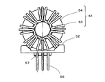
- FIG. 3 is a view showing a coil component 51 attached to the motor drive circuit 21 of FIG. 1 and a pedestal 52 for attaching to the motor drive circuit 21 while supporting the coil component 51.
- the coil component 51 includes a coil 53 and a core 54 (or a core case in which the core is accommodated), and three sets of coil conductors 55 are wound around the donut-shaped core 54 to form the coil 53.
- the pedestal 52 is provided with six terminal holes 57, and the end portions of the coil conducting wires 55 are inserted one by one so that the distance between them is widened.
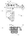
- FIG. 4 shows the pedestal 52 of FIG. 3, wherein (a) is a plan view, (b) is a rear view, (c) is a right side view, (d) is a front view, and (e) is a bottom view. is there.
- the pedestal 52 is provided with an elongated protrusion 56, and a terminal hole 57 into which the coil conductor 55 is inserted is formed in the protrusion 56.
- the terminal hole 57 is perforated so as to be biased to the upper side of FIG. As described above, since the position of the terminal hole 57 is biased in one direction, when the coil conductor 55 is electrically connected to the motor drive circuit 21, the coil conductor 55 inserted into the terminal hole 57 will be described later.
- FIG. 6 shows the case member 58 of FIG. 5, (a) is a perspective view of the back side of the surface shown in FIG. 5 (a) as viewed from above, and (b) is shown in FIG. 5 (a). It is a perspective view which shows the surface side.
- FIG. 6B three joining protrusions 61 are provided on the bus bar 60 provided along one end of the pedestal mounting hole 59.
Landscapes
- Engineering & Computer Science (AREA)
- Power Engineering (AREA)
- Mechanical Engineering (AREA)
- General Engineering & Computer Science (AREA)
- Physics & Mathematics (AREA)
- Electromagnetism (AREA)
- Microelectronics & Electronic Packaging (AREA)
- Compressor (AREA)
- Applications Or Details Of Rotary Compressors (AREA)
- Coils Or Transformers For Communication (AREA)
- Inverter Devices (AREA)
Abstract
Description
図1は、本発明の一実施態様に係るインバータ一体型電動圧縮機1の基本構成として、車両空調装置用のスクロール型電動圧縮機の例を示している。図1において、2は、固定スクロール3と可動スクロール4からなる圧縮機構を示している。可動スクロール4は、ボールカップリング5を介して自転が阻止された状態で、固定スクロール3に対して旋回されるようになっている。圧縮機ハウジング(センターハウジング)6内には、モータ7が組み込まれており、この内蔵モータ7によって主軸8(回転軸)が回転駆動される。主軸8の一端側に配設された偏心ピン9、それに対して回転自在に係合された偏心ブッシュ10を介して、主軸8の回転運動が可動スクロール4の旋回運動に変換されるようになっている。本実施態様では、被圧縮流体としての冷媒を吸入する吸入ポート11が圧縮機ハウジング(フロントハウジング)12に設けられており、吸入された冷媒は、モータ7配置部を通して圧縮機構2へと導かれ、圧縮機構2で圧縮された冷媒は、吐出孔13、吐出室14、圧縮機ハウジング(リアハウジング)15に設けられた吐出ポート16を通して外部回路に送られる。
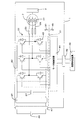
通してモータ駆動用高電圧回路30へ給電され、ノイズフィルタ37、平滑用のコンデンサ27を介してインバータ42に供給され、インバータ42で電源46からの直流が疑似三相交流に変換された後、モータ7へと供給される。モータ制御回路44へは、例えば、車両の空調制御装置48から、低電圧の電力が制御信号用コネクタ49を介して供給される。図2では、この制御信号用コネクタ49と、高電圧用コネクタ47とは、離れた位置に図示してあるが、実際には、図1に示した同一のコネクタ28内に装備されている。制御回路26に、シールドプレート31が固定され、このシールドプレート31が、図2に示すように、モータ駆動用高電圧回路30と制御用低電圧回路45を備えた制御回路26との間に介在され、モータ駆動用高電圧回路30を極力広い範囲にわたって覆い、モータ駆動用高電圧回路30から制御用低電圧回路45側へのノイズの影響を抑制している。
2 圧縮機構
3 固定スクロール
4 可動スクロール
5 ボールカップリング
6 圧縮機ハウジング(センターハウジング)
7 モータ
8 主軸
9 偏心ピン
10 偏心ブッシュ
11 吸入ポート
12 圧縮機ハウジング(フロントハウジング)
13 吐出孔
14 吐出室
15 圧縮機ハウジング(リアハウジング)
16 吐出ポート
21 モータ駆動回路
22 仕切壁
23 密封端子
24 リード線
25 IPM
26 制御回路
27 コンデンサ
28 コネクタ
29 蓋部材
30 モータ駆動用高電圧回路
31 シールドプレート
37 ノイズフィルタ
41 モータ巻線
42 インバータ
43 パワー素子
44 モータ制御回路
45 制御用低電圧回路
46 外部電源
47 高電圧用コネクタ
48 空調制御装置
49 制御信号用コネクタ
51 コイル部品
52 台座
53 コイル
54 コア
55 導線
56 突起
57 端子孔
58 ケース部材
59 台座取付け孔
60 バスバー
61 接合用突起
Claims (7)
- モータが内蔵され、インバータを含むモータ駆動回路が圧縮機ハウジングで囲まれた収容空間内に設けられたインバータ一体型電動圧縮機において、
複数本の導線が並行に巻かれたコイル部品が、台座を介して前記モータ駆動回路に取り付けられ、該台座には、前記モータ駆動回路を収容するケース部材に設けられた台座取付け孔に嵌合可能な突起が設けられ、該突起設置部に複数の端子孔が配設され、該複数の端子孔には、前記コイル部品からの複数本の導線が互いの間隔が広げられるようにして各1本ずつ挿入され、各導線の末端が前記モータ駆動回路と電気的に接続されていることを特徴とするインバータ一体型電動圧縮機。 - 前記導線の末端が、前記モータ駆動回路に設けられたバスバーに接合されている、請求項1に記載のインバータ一体型電動圧縮機。
- 前記端子孔が、前記突起設置部の前記バスバー側に偏って穿孔されており、該突起設置部のバスバー側において前記導線が露出されている、請求項2に記載のインバータ一体型電動圧縮機。
- 前記バスバーの先端に、複数の接合用突起が設けられている、請求項2または3に記載のインバータ一体型電動圧縮機。
- 前記接合がTIG溶接により行われている、請求項2~4のいずれかに記載のインバータ一体型電動圧縮機。
- 前記端子孔の前記コイル部品側開口の周縁部に、面取りが施されている、請求項1~5のいずれかに記載のインバータ一体型電動圧縮機。
- 車両空調装置用圧縮機からなる、請求項1~6のいずれかに記載のインバータ一体型電動圧縮機。
Priority Applications (3)
| Application Number | Priority Date | Filing Date | Title |
|---|---|---|---|
| DE112009002657.5T DE112009002657B4 (de) | 2008-11-06 | 2009-11-06 | Elektrischer Verdichter mit integriertem Wechselrichter |
| US13/128,113 US8698364B2 (en) | 2008-11-06 | 2009-11-06 | Inverter-integrated electric compressor |
| CN2009801446695A CN102203420A (zh) | 2008-11-06 | 2009-11-06 | 逆变器一体型电动压缩机 |
Applications Claiming Priority (2)
| Application Number | Priority Date | Filing Date | Title |
|---|---|---|---|
| JP2008285570A JP5138551B2 (ja) | 2008-11-06 | 2008-11-06 | インバータ一体型電動圧縮機 |
| JP2008-285570 | 2008-11-06 |
Publications (1)
| Publication Number | Publication Date |
|---|---|
| WO2010052922A1 true WO2010052922A1 (ja) | 2010-05-14 |
Family
ID=42152735
Family Applications (1)
| Application Number | Title | Priority Date | Filing Date |
|---|---|---|---|
| PCT/JP2009/005921 Ceased WO2010052922A1 (ja) | 2008-11-06 | 2009-11-06 | インバータ一体型電動圧縮機 |
Country Status (5)
| Country | Link |
|---|---|
| US (1) | US8698364B2 (ja) |
| JP (1) | JP5138551B2 (ja) |
| CN (1) | CN102203420A (ja) |
| DE (1) | DE112009002657B4 (ja) |
| WO (1) | WO2010052922A1 (ja) |
Cited By (2)
| Publication number | Priority date | Publication date | Assignee | Title |
|---|---|---|---|---|
| WO2017149649A1 (ja) * | 2016-03-01 | 2017-09-08 | 三菱電機株式会社 | 電子回路基板およびコイル装置 |
| WO2026078956A1 (ja) * | 2024-10-08 | 2026-04-16 | 株式会社Ihi | 回転機械 |
Families Citing this family (23)
| Publication number | Priority date | Publication date | Assignee | Title |
|---|---|---|---|---|
| JP5308917B2 (ja) * | 2009-05-29 | 2013-10-09 | サンデン株式会社 | インバータ一体型電動圧縮機 |
| WO2014058843A2 (en) * | 2012-10-08 | 2014-04-17 | Trane International Inc. | Hvac electrical system power supply packaging system |
| JP6096003B2 (ja) | 2013-02-21 | 2017-03-15 | 三菱重工オートモーティブサーマルシステムズ株式会社 | インバータ一体型電動圧縮機 |
| SG2013069224A (en) * | 2013-09-13 | 2015-04-29 | Rockwell Automation Asia Pacific Business Ctr Pte Ltd | Motor drive with inherent power isolation |
| JP2016019401A (ja) * | 2014-07-10 | 2016-02-01 | 富士電機株式会社 | 電力変換装置一体型電動機 |
| DE102014114837A1 (de) * | 2014-10-13 | 2016-04-14 | Bitzer Kühlmaschinenbau Gmbh | Kältemittelverdichter |
| JP6584911B2 (ja) * | 2015-10-19 | 2019-10-02 | 三菱重工サーマルシステムズ株式会社 | インバータ一体型電動圧縮機及び回路基板、並びに回路基板の製造方法 |
| DE102015122342A1 (de) * | 2015-12-21 | 2017-06-22 | OET GmbH | Kompressor |
| JP6673468B2 (ja) | 2016-03-31 | 2020-03-25 | 株式会社豊田自動織機 | 車載用電動圧縮機 |
| DE112017001684T5 (de) * | 2016-03-31 | 2018-12-13 | Kabushiki Kaisha Toyota Jidoshokki | Fahrzeugseitiger elektrischer Kompressor |
| US10384548B2 (en) * | 2016-04-28 | 2019-08-20 | Ge Global Sourcing Llc | Systems and methods for a vehicle inverter connection bus |
| CN109478823B (zh) * | 2016-07-20 | 2020-12-29 | 日本电产株式会社 | 马达 |
| DE102017100251B4 (de) | 2017-01-09 | 2023-12-14 | Hanon Systems | Anordnung mit einer Vorrichtung zum Aufnehmen und Abstützen von Stromschienen |
| JP6700610B2 (ja) * | 2017-01-12 | 2020-05-27 | 株式会社豊田自動織機 | 車載用流体機械 |
| US10746450B2 (en) | 2017-01-17 | 2020-08-18 | Regal Beloit America, Inc. | Electric motor and method of use |
| JP7135967B2 (ja) | 2019-03-27 | 2022-09-13 | 株式会社豊田自動織機 | 電動圧縮機 |
| DE102019207942A1 (de) | 2019-05-29 | 2020-12-03 | Brose Fahrzeugteile SE & Co. Kommanditgesellschaft, Würzburg | Elektrischer Kältemittelantrieb eines Kraftfahrzeugs |
| KR102723247B1 (ko) * | 2019-10-08 | 2024-10-31 | 한온시스템 주식회사 | 고정력이 향상된 인덕터, 이를 포함하는 인버터 및 모터 시스템 |
| DE202021004447U1 (de) | 2021-02-05 | 2024-08-26 | Brose Fahrzeugteile SE & Co. Kommanditgesellschaft, Würzburg | Befestigungsanordnung eines leiterplattenmontierten Bauelements |
| DE102021201100A1 (de) | 2021-02-05 | 2022-08-11 | Brose Fahrzeugteile SE & Co. Kommanditgesellschaft, Würzburg | Befestigungsanordnung eines leiterplattenmontierten Bauelements |
| DE102021201099A1 (de) | 2021-02-05 | 2022-08-11 | Brose Fahrzeugteile SE & Co. Kommanditgesellschaft, Würzburg | Befestigungsanordnung eines leiterplattenmontierten Bauelements |
| JP7497698B2 (ja) * | 2021-03-31 | 2024-06-11 | 株式会社豊田自動織機 | 流体機械 |
| DE102023002782A1 (de) * | 2023-07-07 | 2025-01-09 | Mercedes-Benz Group AG | Leistungsversorgungseinrichtung für ein Kraftfahrzeug, insbesondere einen Kraftwagen, sowie Kraftfahrzeug |
Citations (4)
| Publication number | Priority date | Publication date | Assignee | Title |
|---|---|---|---|---|
| JPS59160420A (ja) * | 1983-01-15 | 1984-09-11 | エ−・ゲ−・オ−・エレクトロ−ゲレ−テ・ブランク・ウント・フイツシエル | 電気調理板 |
| JPH0716526U (ja) * | 1993-08-09 | 1995-03-17 | 住友電装株式会社 | 回路絶縁板 |
| JPH08335843A (ja) * | 1995-06-06 | 1996-12-17 | Enomoto:Kk | 水晶デバイス及びその製造方法 |
| JP2008193767A (ja) * | 2007-02-01 | 2008-08-21 | Mitsubishi Heavy Ind Ltd | バスバー接続構造およびインバータ一体型電動圧縮機 |
Family Cites Families (8)
| Publication number | Priority date | Publication date | Assignee | Title |
|---|---|---|---|---|
| JPH06102053B2 (ja) | 1989-06-14 | 1994-12-14 | 松下電器産業株式会社 | 炊飯器 |
| JPH0468511U (ja) * | 1990-10-24 | 1992-06-17 | ||
| JP2733415B2 (ja) | 1992-07-16 | 1998-03-30 | 富士電気化学株式会社 | チョークコイル |
| TW407394B (en) * | 1997-10-16 | 2000-10-01 | Toshiba Corp | Frequency converter to output electric driving power to motor and filter installed on it |
| JP2002057047A (ja) * | 2000-08-08 | 2002-02-22 | Minebea Co Ltd | コモンモードチョークコイル |
| JP2002198236A (ja) * | 2000-12-27 | 2002-07-12 | Minebea Co Ltd | コモンモードチョークコイル |
| EP1363026A3 (en) * | 2002-04-26 | 2004-09-01 | Denso Corporation | Invertor integrated motor for an automotive vehicle |
| JP5247045B2 (ja) | 2007-02-22 | 2013-07-24 | サンデン株式会社 | インバータ一体型電動圧縮機の製造方法 |
-
2008
- 2008-11-06 JP JP2008285570A patent/JP5138551B2/ja not_active Expired - Fee Related
-
2009
- 2009-11-06 DE DE112009002657.5T patent/DE112009002657B4/de not_active Expired - Fee Related
- 2009-11-06 WO PCT/JP2009/005921 patent/WO2010052922A1/ja not_active Ceased
- 2009-11-06 CN CN2009801446695A patent/CN102203420A/zh active Pending
- 2009-11-06 US US13/128,113 patent/US8698364B2/en active Active
Patent Citations (4)
| Publication number | Priority date | Publication date | Assignee | Title |
|---|---|---|---|---|
| JPS59160420A (ja) * | 1983-01-15 | 1984-09-11 | エ−・ゲ−・オ−・エレクトロ−ゲレ−テ・ブランク・ウント・フイツシエル | 電気調理板 |
| JPH0716526U (ja) * | 1993-08-09 | 1995-03-17 | 住友電装株式会社 | 回路絶縁板 |
| JPH08335843A (ja) * | 1995-06-06 | 1996-12-17 | Enomoto:Kk | 水晶デバイス及びその製造方法 |
| JP2008193767A (ja) * | 2007-02-01 | 2008-08-21 | Mitsubishi Heavy Ind Ltd | バスバー接続構造およびインバータ一体型電動圧縮機 |
Cited By (3)
| Publication number | Priority date | Publication date | Assignee | Title |
|---|---|---|---|---|
| WO2017149649A1 (ja) * | 2016-03-01 | 2017-09-08 | 三菱電機株式会社 | 電子回路基板およびコイル装置 |
| JPWO2017149649A1 (ja) * | 2016-03-01 | 2018-06-07 | 三菱電機株式会社 | 電子回路基板およびコイル装置 |
| WO2026078956A1 (ja) * | 2024-10-08 | 2026-04-16 | 株式会社Ihi | 回転機械 |
Also Published As
| Publication number | Publication date |
|---|---|
| DE112009002657B4 (de) | 2015-12-24 |
| DE112009002657T5 (de) | 2012-06-14 |
| DE112009002657T8 (de) | 2013-01-03 |
| CN102203420A (zh) | 2011-09-28 |
| US8698364B2 (en) | 2014-04-15 |
| JP2010112260A (ja) | 2010-05-20 |
| JP5138551B2 (ja) | 2013-02-06 |
| US20110206544A1 (en) | 2011-08-25 |
Similar Documents
| Publication | Publication Date | Title |
|---|---|---|
| JP5138551B2 (ja) | インバータ一体型電動圧縮機 | |
| JP5261139B2 (ja) | インバータ一体型電動圧縮機 | |
| JP5416388B2 (ja) | インバータ一体型電動圧縮機 | |
| JP5291436B2 (ja) | インバータ一体型電動圧縮機 | |
| US8159100B2 (en) | Integrated electronic compressor | |
| CA2895591C (en) | Electric motor and electric pump | |
| JP2011144788A (ja) | 電動圧縮機 | |
| US7955141B2 (en) | Inverter connection terminal with cables attached to parts of the terminal projecting from upper and lower surfaces of a plate | |
| US10938269B2 (en) | Motor with stress absorbing portions | |
| WO2015141272A1 (ja) | インバータ一体型電動圧縮機 | |
| CN105317655A (zh) | 电动压缩机 | |
| KR20110135221A (ko) | 전동식압축기의 스테이터 및 그 조립방법 | |
| WO2014104121A1 (ja) | 電動モータおよび電動ポンプ | |
| WO2017163810A1 (ja) | インバーター体型電動圧縮機 | |
| WO2005113982A1 (ja) | インバータ装置一体型電動圧縮機及びこれを適用した車両用空調装置 | |
| EP2623787B1 (en) | Motor-driven compressor | |
| US20190305625A1 (en) | Motor | |
| JP2002320366A (ja) | ブラシレスモータ | |
| US20130202461A1 (en) | Motor-driven compressor | |
| JP2021132427A (ja) | 車載用電動圧縮機 | |
| JP7596645B2 (ja) | 電動圧縮機 | |
| JP5534905B2 (ja) | 電動機、電動機の結線方法及びこの電動機を用いた換気送風機 | |
| JP4652924B2 (ja) | モータの製造方法及びモータ | |
| JP2020162270A (ja) | 電動圧縮機 | |
| JP2007267490A (ja) | モータハウジング及びモータ |
Legal Events
| Date | Code | Title | Description |
|---|---|---|---|
| WWE | Wipo information: entry into national phase |
Ref document number: 200980144669.5 Country of ref document: CN |
|
| 121 | Ep: the epo has been informed by wipo that ep was designated in this application |
Ref document number: 09824622 Country of ref document: EP Kind code of ref document: A1 |
|
| WWE | Wipo information: entry into national phase |
Ref document number: 13128113 Country of ref document: US |
|
| WWE | Wipo information: entry into national phase |
Ref document number: 1120090026575 Country of ref document: DE |
|
| 122 | Ep: pct application non-entry in european phase |
Ref document number: 09824622 Country of ref document: EP Kind code of ref document: A1 |