WO2010050039A1 - ハイブリッド車両およびその制御方法 - Google Patents
ハイブリッド車両およびその制御方法 Download PDFInfo
- Publication number
- WO2010050039A1 WO2010050039A1 PCT/JP2008/069861 JP2008069861W WO2010050039A1 WO 2010050039 A1 WO2010050039 A1 WO 2010050039A1 JP 2008069861 W JP2008069861 W JP 2008069861W WO 2010050039 A1 WO2010050039 A1 WO 2010050039A1
- Authority
- WO
- WIPO (PCT)
- Prior art keywords
- power storage
- storage device
- sub power
- switching
- voltage
- Prior art date
Links
- 238000000034 method Methods 0.000 title claims abstract description 208
- 238000003860 storage Methods 0.000 claims abstract description 314
- 230000008569 process Effects 0.000 claims abstract description 183
- 238000006243 chemical reaction Methods 0.000 claims abstract description 17
- 230000002457 bidirectional effect Effects 0.000 claims abstract description 16
- 238000002485 combustion reaction Methods 0.000 claims description 49
- 238000012545 processing Methods 0.000 claims description 44
- 230000000670 limiting effect Effects 0.000 claims description 25
- 238000012937 correction Methods 0.000 claims description 10
- 230000002829 reductive effect Effects 0.000 claims description 9
- 230000008859 change Effects 0.000 claims description 8
- 230000007423 decrease Effects 0.000 abstract description 7
- 230000004044 response Effects 0.000 abstract description 6
- 239000003990 capacitor Substances 0.000 description 13
- 230000007246 mechanism Effects 0.000 description 12
- 238000009499 grossing Methods 0.000 description 11
- 238000010586 diagram Methods 0.000 description 10
- 239000000446 fuel Substances 0.000 description 6
- 230000006870 function Effects 0.000 description 6
- 230000002411 adverse Effects 0.000 description 5
- 238000007599 discharging Methods 0.000 description 5
- 230000001172 regenerating effect Effects 0.000 description 5
- NKYDKCVZNMNZCM-UHFFFAOYSA-N 5-chloro-3h-1,3-benzothiazole-2-thione Chemical compound ClC1=CC=C2SC(S)=NC2=C1 NKYDKCVZNMNZCM-UHFFFAOYSA-N 0.000 description 4
- 101100533727 Arabidopsis thaliana SMR3 gene Proteins 0.000 description 3
- 101100368940 Caenorhabditis elegans tbb-2 gene Proteins 0.000 description 3
- 101100533725 Mus musculus Smr3a gene Proteins 0.000 description 3
- 101100149716 Rattus norvegicus Vcsa1 gene Proteins 0.000 description 3
- 101150037481 SMR1 gene Proteins 0.000 description 3
- 101100286750 Saccharomyces cerevisiae (strain ATCC 204508 / S288c) ILV2 gene Proteins 0.000 description 3
- 101100152546 Uromyces fabae TBB1 gene Proteins 0.000 description 3
- 238000001514 detection method Methods 0.000 description 3
- 238000011084 recovery Methods 0.000 description 3
- 101100028962 Saccharomyces cerevisiae (strain ATCC 204508 / S288c) PDR1 gene Proteins 0.000 description 2
- 101150096622 Smr2 gene Proteins 0.000 description 2
- 230000003247 decreasing effect Effects 0.000 description 2
- 238000005259 measurement Methods 0.000 description 2
- 230000009467 reduction Effects 0.000 description 2
- 230000008929 regeneration Effects 0.000 description 2
- 238000011069 regeneration method Methods 0.000 description 2
- 239000004065 semiconductor Substances 0.000 description 2
- HBBGRARXTFLTSG-UHFFFAOYSA-N Lithium ion Chemical compound [Li+] HBBGRARXTFLTSG-UHFFFAOYSA-N 0.000 description 1
- 230000001174 ascending effect Effects 0.000 description 1
- 230000000694 effects Effects 0.000 description 1
- 230000005669 field effect Effects 0.000 description 1
- 229910001416 lithium ion Inorganic materials 0.000 description 1
- 230000014759 maintenance of location Effects 0.000 description 1
- 229910052987 metal hydride Inorganic materials 0.000 description 1
- 238000012986 modification Methods 0.000 description 1
- 230000004048 modification Effects 0.000 description 1
- 230000007935 neutral effect Effects 0.000 description 1
- 229910052759 nickel Inorganic materials 0.000 description 1
- PXHVJJICTQNCMI-UHFFFAOYSA-N nickel Substances [Ni] PXHVJJICTQNCMI-UHFFFAOYSA-N 0.000 description 1
- -1 nickel metal hydride Chemical class 0.000 description 1
- 238000002360 preparation method Methods 0.000 description 1
- 230000002441 reversible effect Effects 0.000 description 1
- 230000001360 synchronised effect Effects 0.000 description 1
Images


Classifications
-
- B—PERFORMING OPERATIONS; TRANSPORTING
- B60—VEHICLES IN GENERAL
- B60K—ARRANGEMENT OR MOUNTING OF PROPULSION UNITS OR OF TRANSMISSIONS IN VEHICLES; ARRANGEMENT OR MOUNTING OF PLURAL DIVERSE PRIME-MOVERS IN VEHICLES; AUXILIARY DRIVES FOR VEHICLES; INSTRUMENTATION OR DASHBOARDS FOR VEHICLES; ARRANGEMENTS IN CONNECTION WITH COOLING, AIR INTAKE, GAS EXHAUST OR FUEL SUPPLY OF PROPULSION UNITS IN VEHICLES
- B60K6/00—Arrangement or mounting of plural diverse prime-movers for mutual or common propulsion, e.g. hybrid propulsion systems comprising electric motors and internal combustion engines ; Control systems therefor, i.e. systems controlling two or more prime movers, or controlling one of these prime movers and any of the transmission, drive or drive units Informative references: mechanical gearings with secondary electric drive F16H3/72; arrangements for handling mechanical energy structurally associated with the dynamo-electric machine H02K7/00; machines comprising structurally interrelated motor and generator parts H02K51/00; dynamo-electric machines not otherwise provided for in H02K see H02K99/00
- B60K6/20—Arrangement or mounting of plural diverse prime-movers for mutual or common propulsion, e.g. hybrid propulsion systems comprising electric motors and internal combustion engines ; Control systems therefor, i.e. systems controlling two or more prime movers, or controlling one of these prime movers and any of the transmission, drive or drive units Informative references: mechanical gearings with secondary electric drive F16H3/72; arrangements for handling mechanical energy structurally associated with the dynamo-electric machine H02K7/00; machines comprising structurally interrelated motor and generator parts H02K51/00; dynamo-electric machines not otherwise provided for in H02K see H02K99/00 the prime-movers consisting of electric motors and internal combustion engines, e.g. HEVs
- B60K6/42—Arrangement or mounting of plural diverse prime-movers for mutual or common propulsion, e.g. hybrid propulsion systems comprising electric motors and internal combustion engines ; Control systems therefor, i.e. systems controlling two or more prime movers, or controlling one of these prime movers and any of the transmission, drive or drive units Informative references: mechanical gearings with secondary electric drive F16H3/72; arrangements for handling mechanical energy structurally associated with the dynamo-electric machine H02K7/00; machines comprising structurally interrelated motor and generator parts H02K51/00; dynamo-electric machines not otherwise provided for in H02K see H02K99/00 the prime-movers consisting of electric motors and internal combustion engines, e.g. HEVs characterised by the architecture of the hybrid electric vehicle
- B60K6/44—Series-parallel type
- B60K6/445—Differential gearing distribution type
-
- B—PERFORMING OPERATIONS; TRANSPORTING
- B60—VEHICLES IN GENERAL
- B60L—PROPULSION OF ELECTRICALLY-PROPELLED VEHICLES; SUPPLYING ELECTRIC POWER FOR AUXILIARY EQUIPMENT OF ELECTRICALLY-PROPELLED VEHICLES; ELECTRODYNAMIC BRAKE SYSTEMS FOR VEHICLES IN GENERAL; MAGNETIC SUSPENSION OR LEVITATION FOR VEHICLES; MONITORING OPERATING VARIABLES OF ELECTRICALLY-PROPELLED VEHICLES; ELECTRIC SAFETY DEVICES FOR ELECTRICALLY-PROPELLED VEHICLES
- B60L3/00—Electric devices on electrically-propelled vehicles for safety purposes; Monitoring operating variables, e.g. speed, deceleration or energy consumption
- B60L3/0023—Detecting, eliminating, remedying or compensating for drive train abnormalities, e.g. failures within the drive train
- B60L3/0046—Detecting, eliminating, remedying or compensating for drive train abnormalities, e.g. failures within the drive train relating to electric energy storage systems, e.g. batteries or capacitors
-
- B—PERFORMING OPERATIONS; TRANSPORTING
- B60—VEHICLES IN GENERAL
- B60L—PROPULSION OF ELECTRICALLY-PROPELLED VEHICLES; SUPPLYING ELECTRIC POWER FOR AUXILIARY EQUIPMENT OF ELECTRICALLY-PROPELLED VEHICLES; ELECTRODYNAMIC BRAKE SYSTEMS FOR VEHICLES IN GENERAL; MAGNETIC SUSPENSION OR LEVITATION FOR VEHICLES; MONITORING OPERATING VARIABLES OF ELECTRICALLY-PROPELLED VEHICLES; ELECTRIC SAFETY DEVICES FOR ELECTRICALLY-PROPELLED VEHICLES
- B60L50/00—Electric propulsion with power supplied within the vehicle
- B60L50/10—Electric propulsion with power supplied within the vehicle using propulsion power supplied by engine-driven generators, e.g. generators driven by combustion engines
- B60L50/16—Electric propulsion with power supplied within the vehicle using propulsion power supplied by engine-driven generators, e.g. generators driven by combustion engines with provision for separate direct mechanical propulsion
-
- B—PERFORMING OPERATIONS; TRANSPORTING
- B60—VEHICLES IN GENERAL
- B60L—PROPULSION OF ELECTRICALLY-PROPELLED VEHICLES; SUPPLYING ELECTRIC POWER FOR AUXILIARY EQUIPMENT OF ELECTRICALLY-PROPELLED VEHICLES; ELECTRODYNAMIC BRAKE SYSTEMS FOR VEHICLES IN GENERAL; MAGNETIC SUSPENSION OR LEVITATION FOR VEHICLES; MONITORING OPERATING VARIABLES OF ELECTRICALLY-PROPELLED VEHICLES; ELECTRIC SAFETY DEVICES FOR ELECTRICALLY-PROPELLED VEHICLES
- B60L50/00—Electric propulsion with power supplied within the vehicle
- B60L50/50—Electric propulsion with power supplied within the vehicle using propulsion power supplied by batteries or fuel cells
- B60L50/60—Electric propulsion with power supplied within the vehicle using propulsion power supplied by batteries or fuel cells using power supplied by batteries
- B60L50/61—Electric propulsion with power supplied within the vehicle using propulsion power supplied by batteries or fuel cells using power supplied by batteries by batteries charged by engine-driven generators, e.g. series hybrid electric vehicles
-
- B—PERFORMING OPERATIONS; TRANSPORTING
- B60—VEHICLES IN GENERAL
- B60L—PROPULSION OF ELECTRICALLY-PROPELLED VEHICLES; SUPPLYING ELECTRIC POWER FOR AUXILIARY EQUIPMENT OF ELECTRICALLY-PROPELLED VEHICLES; ELECTRODYNAMIC BRAKE SYSTEMS FOR VEHICLES IN GENERAL; MAGNETIC SUSPENSION OR LEVITATION FOR VEHICLES; MONITORING OPERATING VARIABLES OF ELECTRICALLY-PROPELLED VEHICLES; ELECTRIC SAFETY DEVICES FOR ELECTRICALLY-PROPELLED VEHICLES
- B60L58/00—Methods or circuit arrangements for monitoring or controlling batteries or fuel cells, specially adapted for electric vehicles
- B60L58/10—Methods or circuit arrangements for monitoring or controlling batteries or fuel cells, specially adapted for electric vehicles for monitoring or controlling batteries
- B60L58/18—Methods or circuit arrangements for monitoring or controlling batteries or fuel cells, specially adapted for electric vehicles for monitoring or controlling batteries of two or more battery modules
- B60L58/21—Methods or circuit arrangements for monitoring or controlling batteries or fuel cells, specially adapted for electric vehicles for monitoring or controlling batteries of two or more battery modules having the same nominal voltage
-
- B—PERFORMING OPERATIONS; TRANSPORTING
- B60—VEHICLES IN GENERAL
- B60W—CONJOINT CONTROL OF VEHICLE SUB-UNITS OF DIFFERENT TYPE OR DIFFERENT FUNCTION; CONTROL SYSTEMS SPECIALLY ADAPTED FOR HYBRID VEHICLES; ROAD VEHICLE DRIVE CONTROL SYSTEMS FOR PURPOSES NOT RELATED TO THE CONTROL OF A PARTICULAR SUB-UNIT
- B60W10/00—Conjoint control of vehicle sub-units of different type or different function
- B60W10/04—Conjoint control of vehicle sub-units of different type or different function including control of propulsion units
- B60W10/06—Conjoint control of vehicle sub-units of different type or different function including control of propulsion units including control of combustion engines
-
- B—PERFORMING OPERATIONS; TRANSPORTING
- B60—VEHICLES IN GENERAL
- B60W—CONJOINT CONTROL OF VEHICLE SUB-UNITS OF DIFFERENT TYPE OR DIFFERENT FUNCTION; CONTROL SYSTEMS SPECIALLY ADAPTED FOR HYBRID VEHICLES; ROAD VEHICLE DRIVE CONTROL SYSTEMS FOR PURPOSES NOT RELATED TO THE CONTROL OF A PARTICULAR SUB-UNIT
- B60W10/00—Conjoint control of vehicle sub-units of different type or different function
- B60W10/04—Conjoint control of vehicle sub-units of different type or different function including control of propulsion units
- B60W10/08—Conjoint control of vehicle sub-units of different type or different function including control of propulsion units including control of electric propulsion units, e.g. motors or generators
-
- B—PERFORMING OPERATIONS; TRANSPORTING
- B60—VEHICLES IN GENERAL
- B60W—CONJOINT CONTROL OF VEHICLE SUB-UNITS OF DIFFERENT TYPE OR DIFFERENT FUNCTION; CONTROL SYSTEMS SPECIALLY ADAPTED FOR HYBRID VEHICLES; ROAD VEHICLE DRIVE CONTROL SYSTEMS FOR PURPOSES NOT RELATED TO THE CONTROL OF A PARTICULAR SUB-UNIT
- B60W20/00—Control systems specially adapted for hybrid vehicles
- B60W20/10—Controlling the power contribution of each of the prime movers to meet required power demand
- B60W20/13—Controlling the power contribution of each of the prime movers to meet required power demand in order to stay within battery power input or output limits; in order to prevent overcharging or battery depletion
-
- B—PERFORMING OPERATIONS; TRANSPORTING
- B60—VEHICLES IN GENERAL
- B60W—CONJOINT CONTROL OF VEHICLE SUB-UNITS OF DIFFERENT TYPE OR DIFFERENT FUNCTION; CONTROL SYSTEMS SPECIALLY ADAPTED FOR HYBRID VEHICLES; ROAD VEHICLE DRIVE CONTROL SYSTEMS FOR PURPOSES NOT RELATED TO THE CONTROL OF A PARTICULAR SUB-UNIT
- B60W30/00—Purposes of road vehicle drive control systems not related to the control of a particular sub-unit, e.g. of systems using conjoint control of vehicle sub-units
- B60W30/18—Propelling the vehicle
- B60W30/18009—Propelling the vehicle related to particular drive situations
- B60W30/18054—Propelling the vehicle related to particular drive situations at stand still, e.g. engine in idling state
-
- B—PERFORMING OPERATIONS; TRANSPORTING
- B60—VEHICLES IN GENERAL
- B60K—ARRANGEMENT OR MOUNTING OF PROPULSION UNITS OR OF TRANSMISSIONS IN VEHICLES; ARRANGEMENT OR MOUNTING OF PLURAL DIVERSE PRIME-MOVERS IN VEHICLES; AUXILIARY DRIVES FOR VEHICLES; INSTRUMENTATION OR DASHBOARDS FOR VEHICLES; ARRANGEMENTS IN CONNECTION WITH COOLING, AIR INTAKE, GAS EXHAUST OR FUEL SUPPLY OF PROPULSION UNITS IN VEHICLES
- B60K1/00—Arrangement or mounting of electrical propulsion units
- B60K1/02—Arrangement or mounting of electrical propulsion units comprising more than one electric motor
-
- B—PERFORMING OPERATIONS; TRANSPORTING
- B60—VEHICLES IN GENERAL
- B60L—PROPULSION OF ELECTRICALLY-PROPELLED VEHICLES; SUPPLYING ELECTRIC POWER FOR AUXILIARY EQUIPMENT OF ELECTRICALLY-PROPELLED VEHICLES; ELECTRODYNAMIC BRAKE SYSTEMS FOR VEHICLES IN GENERAL; MAGNETIC SUSPENSION OR LEVITATION FOR VEHICLES; MONITORING OPERATING VARIABLES OF ELECTRICALLY-PROPELLED VEHICLES; ELECTRIC SAFETY DEVICES FOR ELECTRICALLY-PROPELLED VEHICLES
- B60L2210/00—Converter types
- B60L2210/20—AC to AC converters
-
- B—PERFORMING OPERATIONS; TRANSPORTING
- B60—VEHICLES IN GENERAL
- B60L—PROPULSION OF ELECTRICALLY-PROPELLED VEHICLES; SUPPLYING ELECTRIC POWER FOR AUXILIARY EQUIPMENT OF ELECTRICALLY-PROPELLED VEHICLES; ELECTRODYNAMIC BRAKE SYSTEMS FOR VEHICLES IN GENERAL; MAGNETIC SUSPENSION OR LEVITATION FOR VEHICLES; MONITORING OPERATING VARIABLES OF ELECTRICALLY-PROPELLED VEHICLES; ELECTRIC SAFETY DEVICES FOR ELECTRICALLY-PROPELLED VEHICLES
- B60L2220/00—Electrical machine types; Structures or applications thereof
- B60L2220/10—Electrical machine types
- B60L2220/14—Synchronous machines
-
- B—PERFORMING OPERATIONS; TRANSPORTING
- B60—VEHICLES IN GENERAL
- B60L—PROPULSION OF ELECTRICALLY-PROPELLED VEHICLES; SUPPLYING ELECTRIC POWER FOR AUXILIARY EQUIPMENT OF ELECTRICALLY-PROPELLED VEHICLES; ELECTRODYNAMIC BRAKE SYSTEMS FOR VEHICLES IN GENERAL; MAGNETIC SUSPENSION OR LEVITATION FOR VEHICLES; MONITORING OPERATING VARIABLES OF ELECTRICALLY-PROPELLED VEHICLES; ELECTRIC SAFETY DEVICES FOR ELECTRICALLY-PROPELLED VEHICLES
- B60L2260/00—Operating Modes
- B60L2260/20—Drive modes; Transition between modes
- B60L2260/22—Standstill, e.g. zero speed
-
- B—PERFORMING OPERATIONS; TRANSPORTING
- B60—VEHICLES IN GENERAL
- B60L—PROPULSION OF ELECTRICALLY-PROPELLED VEHICLES; SUPPLYING ELECTRIC POWER FOR AUXILIARY EQUIPMENT OF ELECTRICALLY-PROPELLED VEHICLES; ELECTRODYNAMIC BRAKE SYSTEMS FOR VEHICLES IN GENERAL; MAGNETIC SUSPENSION OR LEVITATION FOR VEHICLES; MONITORING OPERATING VARIABLES OF ELECTRICALLY-PROPELLED VEHICLES; ELECTRIC SAFETY DEVICES FOR ELECTRICALLY-PROPELLED VEHICLES
- B60L2270/00—Problem solutions or means not otherwise provided for
- B60L2270/10—Emission reduction
- B60L2270/14—Emission reduction of noise
- B60L2270/145—Structure borne vibrations
-
- B—PERFORMING OPERATIONS; TRANSPORTING
- B60—VEHICLES IN GENERAL
- B60L—PROPULSION OF ELECTRICALLY-PROPELLED VEHICLES; SUPPLYING ELECTRIC POWER FOR AUXILIARY EQUIPMENT OF ELECTRICALLY-PROPELLED VEHICLES; ELECTRODYNAMIC BRAKE SYSTEMS FOR VEHICLES IN GENERAL; MAGNETIC SUSPENSION OR LEVITATION FOR VEHICLES; MONITORING OPERATING VARIABLES OF ELECTRICALLY-PROPELLED VEHICLES; ELECTRIC SAFETY DEVICES FOR ELECTRICALLY-PROPELLED VEHICLES
- B60L58/00—Methods or circuit arrangements for monitoring or controlling batteries or fuel cells, specially adapted for electric vehicles
- B60L58/10—Methods or circuit arrangements for monitoring or controlling batteries or fuel cells, specially adapted for electric vehicles for monitoring or controlling batteries
- B60L58/12—Methods or circuit arrangements for monitoring or controlling batteries or fuel cells, specially adapted for electric vehicles for monitoring or controlling batteries responding to state of charge [SoC]
-
- B—PERFORMING OPERATIONS; TRANSPORTING
- B60—VEHICLES IN GENERAL
- B60W—CONJOINT CONTROL OF VEHICLE SUB-UNITS OF DIFFERENT TYPE OR DIFFERENT FUNCTION; CONTROL SYSTEMS SPECIALLY ADAPTED FOR HYBRID VEHICLES; ROAD VEHICLE DRIVE CONTROL SYSTEMS FOR PURPOSES NOT RELATED TO THE CONTROL OF A PARTICULAR SUB-UNIT
- B60W2510/00—Input parameters relating to a particular sub-units
- B60W2510/24—Energy storage means
- B60W2510/242—Energy storage means for electrical energy
- B60W2510/244—Charge state
-
- Y—GENERAL TAGGING OF NEW TECHNOLOGICAL DEVELOPMENTS; GENERAL TAGGING OF CROSS-SECTIONAL TECHNOLOGIES SPANNING OVER SEVERAL SECTIONS OF THE IPC; TECHNICAL SUBJECTS COVERED BY FORMER USPC CROSS-REFERENCE ART COLLECTIONS [XRACs] AND DIGESTS
- Y02—TECHNOLOGIES OR APPLICATIONS FOR MITIGATION OR ADAPTATION AGAINST CLIMATE CHANGE
- Y02T—CLIMATE CHANGE MITIGATION TECHNOLOGIES RELATED TO TRANSPORTATION
- Y02T10/00—Road transport of goods or passengers
- Y02T10/60—Other road transportation technologies with climate change mitigation effect
- Y02T10/62—Hybrid vehicles
-
- Y—GENERAL TAGGING OF NEW TECHNOLOGICAL DEVELOPMENTS; GENERAL TAGGING OF CROSS-SECTIONAL TECHNOLOGIES SPANNING OVER SEVERAL SECTIONS OF THE IPC; TECHNICAL SUBJECTS COVERED BY FORMER USPC CROSS-REFERENCE ART COLLECTIONS [XRACs] AND DIGESTS
- Y02—TECHNOLOGIES OR APPLICATIONS FOR MITIGATION OR ADAPTATION AGAINST CLIMATE CHANGE
- Y02T—CLIMATE CHANGE MITIGATION TECHNOLOGIES RELATED TO TRANSPORTATION
- Y02T10/00—Road transport of goods or passengers
- Y02T10/60—Other road transportation technologies with climate change mitigation effect
- Y02T10/70—Energy storage systems for electromobility, e.g. batteries
-
- Y—GENERAL TAGGING OF NEW TECHNOLOGICAL DEVELOPMENTS; GENERAL TAGGING OF CROSS-SECTIONAL TECHNOLOGIES SPANNING OVER SEVERAL SECTIONS OF THE IPC; TECHNICAL SUBJECTS COVERED BY FORMER USPC CROSS-REFERENCE ART COLLECTIONS [XRACs] AND DIGESTS
- Y02—TECHNOLOGIES OR APPLICATIONS FOR MITIGATION OR ADAPTATION AGAINST CLIMATE CHANGE
- Y02T—CLIMATE CHANGE MITIGATION TECHNOLOGIES RELATED TO TRANSPORTATION
- Y02T10/00—Road transport of goods or passengers
- Y02T10/60—Other road transportation technologies with climate change mitigation effect
- Y02T10/7072—Electromobility specific charging systems or methods for batteries, ultracapacitors, supercapacitors or double-layer capacitors
-
- Y—GENERAL TAGGING OF NEW TECHNOLOGICAL DEVELOPMENTS; GENERAL TAGGING OF CROSS-SECTIONAL TECHNOLOGIES SPANNING OVER SEVERAL SECTIONS OF THE IPC; TECHNICAL SUBJECTS COVERED BY FORMER USPC CROSS-REFERENCE ART COLLECTIONS [XRACs] AND DIGESTS
- Y02—TECHNOLOGIES OR APPLICATIONS FOR MITIGATION OR ADAPTATION AGAINST CLIMATE CHANGE
- Y02T—CLIMATE CHANGE MITIGATION TECHNOLOGIES RELATED TO TRANSPORTATION
- Y02T10/00—Road transport of goods or passengers
- Y02T10/60—Other road transportation technologies with climate change mitigation effect
- Y02T10/72—Electric energy management in electromobility
Definitions
- the present invention relates to a hybrid vehicle and a control method therefor, and more specifically to control of a hybrid vehicle equipped with a main power supply device and a plurality of sub power storage devices as a vehicle power source.
- electric vehicles such as electric vehicles, hybrid vehicles, and fuel cell vehicles have been developed and put into practical use as environmentally friendly vehicles.
- These electric vehicles are equipped with a power supply system for supplying motor driving power configured to include a motor for generating vehicle driving force and a power storage device.
- the hybrid vehicle is configured to be able to travel by using the output energy of the internal combustion engine directly or indirectly.
- Patent Document 1 Japanese Patent Application Laid-Open No. 2008-109840
- Patent Document 2 Japanese Patent Application Laid-Open No. 2003-209969
- Patent Document 3 a voltage converter (converter) as a charge / discharge adjustment mechanism is provided for each power storage device (battery).
- Patent Document 3 in Japanese Patent Application Laid-Open No. 2008-167620 (Patent Document 3), in a vehicle equipped with a main power storage device and a plurality of sub power storage devices, a converter corresponding to the main power storage device and a plurality of sub power storage devices are disclosed.
- one of the plurality of sub power storage devices is selectively connected to the converter, and the driving power of the vehicle driving motor is supplied by the main power storage device and the selected sub power storage device. Is done.
- SOC State of Charge
- a plurality of sub power storage devices are used sequentially by connecting a new sub power storage device to the converter.
- the travel distance EV (Electric Vehicle) travel distance
- the connection of the sub power storage device is switched, only the power of the main power storage device can be used, so that the power that can be input and output as a whole power supply system is reduced.
- traveling by only the motor output and traveling by both the motor output and the engine output are selected according to the traveling state. For this reason, the engine is intermittently operated with a start process or a stop process during traveling of the vehicle.
- a charge / discharge request to the power supply system is generated.
- motor power for cranking the engine is output from the power supply system.
- motor power for deceleration control by driving the motor after fuel cut and for using the regenerative brake immediately before the stop is input / output to / from the power supply system.
- the present invention has been made to solve such problems, and an object of the present invention is to provide a main power storage device and a sub power storage device, and a voltage converter (converter) by a plurality of sub power storage devices.
- a voltage converter converter
- a hybrid vehicle includes a motor that generates vehicle driving power, an internal combustion engine, a main power storage device, a power supply line, a first voltage converter, and a plurality of sub power storages provided in parallel with each other.
- An apparatus, a 2nd voltage converter, a connection part, a switching control apparatus, and a travel control part are provided.
- the internal combustion engine is configured to be able to output vehicle drive power independently of the motor.
- the power supply line is configured to supply power to an inverter that drives and controls the motor.
- the first voltage converter is provided between the power supply line and the main power storage device, and is configured to perform bidirectional voltage conversion.
- the second voltage converter is provided between the plurality of sub power storage devices and the power supply line, and configured to perform bidirectional voltage conversion between one of the plurality of sub power storage devices and the power supply line.
- the connecting unit is provided between the plurality of sub power storage devices and the second voltage converter, and selectively connects the selected sub power storage device among the plurality of sub power storage devices to the second voltage converter. Composed.
- the switching control device is configured to control selective connection between the plurality of sub power storage devices and the second voltage converter.
- the travel control unit is configured to distribute the overall required power of the hybrid vehicle to the output power of the motor and the output power of the internal combustion engine. The traveling control unit prohibits the start process of the stopped internal combustion engine and the stop process of the operated internal combustion engine during the connection switching process between the plurality of sub power storage devices and the second voltage converter.
- a method for controlling a hybrid vehicle wherein the hybrid vehicle includes the motor, the internal combustion engine, the main power storage device, the power supply line, the first voltage converter, the plurality of sub power storage devices, 2 voltage converters, a connection unit, a switching control device, and a travel control unit.
- the control method includes a step of determining whether or not a connection switching process between the plurality of sub power storage devices and the second voltage converter is being performed, and a start of the internal combustion engine in a stopped state during the connection switching process. And a step of prohibiting the stop process of the internal combustion engine in the process and the operating state.
- the execution of the start process and the stop process of the internal combustion engine is prohibited. Can be prevented.
- the hybrid vehicle includes a rotation element whose rotation speed is changed by an output change of the internal combustion engine, and a protection control unit that generates one of a start request and a stop request for the internal combustion engine to suppress over-rotation of the rotation element.
- the travel control unit permits the start process or the stop process of the internal combustion engine regardless of whether the connection switching process is being performed.
- the control method further includes a step of permitting a start process or a stop process of the internal combustion engine regardless of whether or not the connection switching process is being performed when a start request or a stop request is generated by the protection control unit.
- the switching control device includes a switching determination unit and a switching prohibition unit.
- the switching determination unit is configured to determine whether or not a switching request for the selected sub power storage device needs to be generated based on a state of charge of the remaining capacity (SOC) of the selected sub power storage device in use.
- the switching prohibiting unit is configured to instruct the switching determining unit not to generate a switching request when the internal combustion engine is in the starting process or the stopping process.
- the control method includes a step of determining whether or not connection switching processing between the plurality of sub power storage devices and the second voltage converter is being performed, and starting the internal combustion engine in a stopped state during the connection switching processing. And a step of prohibiting the stop process of the internal combustion engine in the process and the operating state.
- the start of the connection switching process of the sub power storage device can be prohibited during execution of the start process or the stop process of the internal combustion engine, so that the start / stop process of the internal combustion engine and the sub power storage can be more reliably performed. It is possible to prevent the apparatus connection switching process from being executed simultaneously.
- a hybrid vehicle in another aspect of the present invention, includes a motor that generates vehicle driving power, an internal combustion engine, a main power storage device, a power supply line, a first voltage converter, and a plurality of parallel vehicles.
- a sub power storage device, a second voltage converter, a connection unit, and a switching control device are provided.
- the internal combustion engine is configured to be able to output vehicle drive power independently of the motor.
- the power supply line is configured to supply power to an inverter that drives and controls the motor.
- the first voltage converter is provided between the power supply line and the main power storage device, and is configured to perform bidirectional voltage conversion.
- the second voltage converter is provided between the plurality of sub power storage devices and the power supply line, and configured to perform bidirectional voltage conversion between one of the plurality of sub power storage devices and the power supply line.
- the connecting unit is provided between the plurality of sub power storage devices and the second voltage converter, and selectively connects the selected sub power storage device among the plurality of sub power storage devices to the second voltage converter.
- the switching control device is configured to control selective connection between the plurality of sub power storage devices and the second voltage converter.
- the switching control device includes a switching determination unit that determines whether or not a switching request for the selected sub power storage device needs to be generated based on the state of charge of the remaining capacity (SOC) of the selected sub power storage device in use, and the internal combustion engine is started. And a switching prohibiting unit that instructs the switching determining unit not to generate a switching request for the selected sub power storage device during the processing or the stop processing.
- a method for controlling a hybrid vehicle wherein the hybrid vehicle includes the motor, the internal combustion engine, the main power storage device, the power supply line, the first voltage converter, and the plurality of sub power storage devices described above. , A second voltage converter, a connection unit, and a switching control device.
- the control method includes a step of determining whether or not a connection switching process between the plurality of sub power storage devices and the second voltage converter is being performed, and a start of the internal combustion engine in a stopped state during the connection switching process. And a step of prohibiting the stop process of the internal combustion engine in the process and the operating state.
- the start of the connection switching process of the sub power storage device is prohibited during the start process or the stop process of the internal combustion engine.
- the start process or the stop process of the internal combustion engine it is possible to prevent the occurrence of power input / output accompanying the start / stop of the engine during the connection switching process of the sub power storage device.
- the connection switching process adversely affects the vehicle drivability. It can prevent giving.
- the switching control device further includes a boosting instruction unit, a first power limiting unit, a connection switching control unit, and a second power limiting unit.
- the boosting instruction unit sets the voltage of the power supply line to be higher than the output voltage of the main power storage device and the output voltage of the sub power storage device connected to the second voltage converter after switching.
- the first power limiting unit is configured to gradually reduce the input / output power upper limit value by the selected sub power storage device to zero after the voltage of the power supply line reaches the first voltage.
- the connection switching control unit is configured to switch connections between the plurality of sub power storage devices and the second voltage converter when the input / output power upper limit value is set to zero by the first power limiting unit.
- the second power limiting unit includes a sub power storage device newly connected to the second voltage converter after the connection switching control unit switches the connection between the plurality of sub power storage devices and the second voltage converter.
- the input / output power upper limit value is gradually increased to a value corresponding to the state of charge.
- the control method sets the voltage of the power supply line to be higher than the output voltage of the main power storage device and the output voltage of the sub power storage device connected to the second voltage converter after switching.
- a hybrid vehicle having a power storage configuration that includes a main power storage device and a sub power storage device and shares a voltage converter (converter) with the plurality of power storage devices, It is possible to prevent adverse effects on drivability.
- FIG. 2 is a circuit diagram showing a detailed configuration of each inverter shown in FIG. 1. It is a circuit diagram which shows the detailed structure of each converter shown in FIG. It is a functional block diagram explaining driving control of a hybrid vehicle. It is a flowchart which shows the rough process sequence of the selection sub electrical storage apparatus connection switching process in the hybrid vehicle by embodiment of this invention.
- 6 is a flowchart illustrating details of a sub power storage device switching determination process shown in FIG. 5. It is a flowchart explaining the detail of the pressure
- FIG. 6 It is a flowchart explaining the detail of the connection switching process shown in FIG. 6 is a flowchart for explaining details of a return process shown in FIG. 5. It is an operation waveform diagram at the time of switching processing of a selection sub power storage device in a hybrid vehicle according to an embodiment of the present invention.
- 5 is a first flowchart illustrating a control process for engine start / stop restriction in the hybrid vehicle according to the embodiment of the present invention.
- 6 is a second flowchart illustrating a control process for engine start / stop restriction in the hybrid vehicle according to the embodiment of the present invention.
- FIG. 1 is a diagram showing a main configuration of a hybrid vehicle according to an embodiment of the present invention.
- hybrid vehicle 1 includes batteries BA, BB1, and BB2, which are power storage devices, connection portions 39A and 39B, converters 12A and 12B, smoothing capacitors C1, C2, and CH, and voltage sensor 10A.
- a power supply system for a hybrid vehicle includes a battery BA that is a main power storage device, a power supply line PL2 that supplies power to inverter 14 that drives motor generator MG2, and a main power storage device (BA) and power supply line PL2.
- Converter 12A that is a voltage converter that is provided in between and performs bidirectional voltage conversion, batteries BB1 and BB2 that are a plurality of sub power storage devices provided in parallel to each other, and a plurality of sub power storage devices (BB1 and BB2) )
- the power supply line PL2 and a converter 12B that is a voltage converter that performs bidirectional voltage conversion is selectively connected to any one of the plurality of sub power storage devices (BB1, BB2), and performs bidirectional voltage conversion with the power feed line PL2.
- the sub power storage device (one of BB1 or BB2) and the main power storage device (BA) can output, for example, the maximum power allowed for the electrical load (22 and MG2) connected to the power supply line by simultaneous use.
- the chargeable capacity is set as shown. As a result, traveling at maximum power is possible in EV traveling without using the engine. If the power storage state of the sub power storage device deteriorates, the sub power storage device may be replaced and run further. If the power of the sub power storage device is consumed, the maximum power can be traveled without using the sub power storage device by using the engine in addition to the main power storage device.
- the converter 12B is shared by a plurality of sub power storage devices, so that the number of converters need not be increased by the number of power storage devices.
- a battery may be added in parallel to the batteries BB1 and BB2.
- hybrid vehicle 1 further includes a battery charging device (charging converter) 6 for connection to an external power supply 8 which is a commercial power supply of AC 100V, for example.
- the battery charger 6 converts alternating current into direct current and regulates the voltage to supply battery charging power.
- the configuration enabling external charging includes a system in which the neutral point of the stator coils of motor generators MG1 and MG2 is connected to an AC power supply, and converters 12A and 12B combined to form an AC / DC converter. A functioning method may be used.
- Smoothing capacitor C1 is connected between power supply line PL1A and ground line SL2.
- the voltage sensor 21 ⁇ / b> A detects the voltage VLA across the smoothing capacitor C ⁇ b> 1 and outputs it to the control device 30.
- Converter 12A can boost the voltage across terminals of smoothing capacitor C1 and supply the boosted voltage to power supply line PL2.
- Smoothing capacitor C2 is connected between power supply line PL1B and ground line SL2.
- the voltage sensor 21B detects the voltage VLB across the smoothing capacitor C2 and outputs it to the control device 30.
- Converter 12B can boost the voltage across terminals of smoothing capacitor C2 and supply it to power supply line PL2.
- Smoothing capacitor CH smoothes the voltage boosted by converters 12A and 12B.
- the voltage sensor 13 detects the inter-terminal voltage VH of the smoothing capacitor CH and outputs it to the control device 30.
- converters 12A and 12B can step down voltage VH between terminals smoothed by smoothing capacitor CH and supply it to power supply lines PL1A and PL1B.
- the inverter 14 converts the DC voltage supplied from the converter 12B and / or 12A into a three-phase AC voltage and outputs it to the motor generator MG1.
- Inverter 22 converts the DC voltage applied from converters 12B and / or 12A into a three-phase AC voltage and outputs the same to motor generator MG2.
- the power split mechanism 3 is a mechanism that is coupled to the engine 4 and the motor generators MG1 and MG2 and distributes power between them.
- a planetary gear mechanism having three rotating shafts of a sun gear, a planetary carrier, and a ring gear can be used.
- rotation of two of the three rotation shafts is determined, rotation of the other one rotation shaft is forcibly determined.
- These three rotation shafts are connected to the rotation shafts of engine 4 and motor generators MG1, MG2, respectively.
- the rotating shaft of motor generator MG2 is coupled to wheel 2 by a reduction gear and a differential gear (not shown).
- a reduction gear for the rotation shaft of motor generator MG2 may be further incorporated in power split device 3. That is, the change in the engine output not only changes the engine rotation speed, but also changes the rotation speed of the rotating elements (MG1, MG2, etc.) connected to the power split mechanism 3 through the change in the engine rotation speed.
- the change in the engine output not only changes the engine rotation speed, but also changes the
- Connection portion 39A includes a system main relay SMR2 connected between the positive electrode of battery BA and power supply line PL1A, a system main relay SMR1 connected in series with system main relay SMR2, and a limiting resistor R, A system main relay SMR3 connected between a negative electrode (ground line SL1) of battery BA and node N2 is included.
- System main relays SMR1 to SMR3 are controlled to be in a conductive state (ON) / non-conductive state (OFF) in accordance with relay control signals CONT1 to CONT3 given from control device 30, respectively.
- Voltage sensor 10A measures voltage VA between the terminals of battery BA. Furthermore, the temperature sensor 11A measures the temperature TA of the battery BA, and the current sensor 9A measures the input / output current IA of the battery BA. Measurement values obtained by these sensors are output to the control device 30. Based on these measured values, control device 30 monitors the state of battery BA represented by SOC (State of Charge).
- SOC State of Charge
- Connection portion 39B is provided between power supply line PL1B and ground line SL2 and batteries BB1 and BB2.
- Connection unit 39B includes relay SR1 connected between the positive electrode of battery BB1 and power supply line PL1B, relay SR1G connected between the negative electrode of battery BB1 and ground line SL2, and the positive electrode and power supply line of battery BB2.
- Relay SR2 connected between PL1B and relay SR2G connected between the negative electrode of battery BB2 and ground line SL2.
- Relays SR1 and SR2 are controlled to be in a conductive state (ON) / non-conductive state (OFF) in accordance with relay control signals CONT4 and CONT5 given from control device 30, respectively.
- Relays SR1G and SR2G are controlled to be in a conductive state (ON) / non-conductive state (OFF) in accordance with relay control signals CONT6 and CONT7 given from control device 30, respectively.
- ground line SL2 extends through converters 12A and 12B to inverters 14 and 22 side.
- Voltage sensors 10B1 and 10B2 measure voltages VBB1 and VBB2 between terminals of batteries BB1 and BB2, respectively. Furthermore, temperature sensors 11B1 and 11B2 measure temperatures TBB1 and TBB2 of batteries BB1 and BB2, respectively. Current sensors 9B1 and 9B2 measure input / output currents IB1 and IB2 of batteries BB1 and BB2. Measurement values obtained by these sensors are output to the control device 30. Based on these measured values, control device 30 monitors the states of batteries BB1 and BB2 represented by SOC (State of Charge).
- SOC State of Charge
- batteries BA, BB1, and BB2 for example, secondary batteries such as lead storage batteries, nickel metal hydride batteries, and lithium ion batteries, and large-capacity capacitors such as electric double layer capacitors can be used.
- the inverter 14 is connected to the power supply line PL2 and the ground line SL2. Inverter 14 receives the boosted voltage from converters 12A and / or 12B and drives motor generator MG1 to start engine 4, for example. Inverter 14 returns the electric power generated by motor generator MG1 by the power transmitted from engine 4 to converters 12A and 12B. At this time, converters 12A and 12B are controlled by control device 30 so as to operate as a step-down converter.
- Current sensor 24 detects the current flowing through motor generator MG1 as motor current value MCRT1, and outputs motor current value MCRT1 to control device 30.
- the inverter 22 is connected in parallel with the inverter 14 to the power supply line PL2 and the ground line SL2. Inverter 22 converts the DC voltage output from converters 12 ⁇ / b> A and 12 ⁇ / b> B into a three-phase AC voltage and outputs the same to motor generator MG ⁇ b> 2 driving wheel 2. Inverter 22 returns the electric power generated in motor generator MG2 to converters 12A and 12B along with regenerative braking. At this time, converters 12A and 12B are controlled by control device 30 so as to operate as a step-down converter.
- Current sensor 25 detects the current flowing through motor generator MG2 as motor current value MCRT2, and outputs motor current value MCRT2 to control device 30.
- the control device 30 is composed of a CPU (Central Processing Unit) (not shown) and an electronic control unit (ECU) with a built-in memory, and based on a map and a program stored in the memory, an operation using measured values from each sensor. Perform processing. Note that a part of the control device 30 may be configured to execute predetermined numerical / logical operation processing by hardware such as an electronic circuit.
- CPU Central Processing Unit
- ECU electronice control unit
- control device 30 includes torque command values and rotation speeds of motor generators MG1, MG2, voltages VBA, VBB1, VBB2, VLA, VLB, VH, motor current values MCRT1, MCRT2, and a start signal.
- Control device 30 outputs control signal PWUB for instructing boosting to converter 12B, control signal PWDB for instructing step-down, and a shutdown signal instructing prohibition of operation.
- control device 30 provides control signal PWMI1 for giving a drive instruction to convert inverter 14 to a DC voltage that is output from converters 12A and 12B into an AC voltage for driving motor generator MG1, and motor generator MG1.
- control signal PWMC1 for performing a regeneration instruction for converting the generated AC voltage into a DC voltage and returning it to the converters 12A and 12B is output.
- control device 30 converts control signal PWMI2 for instructing inverter 22 to drive to convert DC voltage into AC voltage for driving motor generator MG2, and AC voltage generated by motor generator MG2 to DC voltage.
- a control signal PWMC2 for performing a regeneration instruction for conversion and returning to the converters 12A and 12B is output.
- FIG. 2 is a circuit diagram showing a detailed configuration of inverters 14 and 22 in FIG.
- inverter 14 includes a U-phase arm 15, a V-phase arm 16, and a W-phase arm 17.
- U-phase arm 15, V-phase arm 16, and W-phase arm 17 are connected in parallel between power supply line PL2 and ground line SL2.
- U-phase arm 15 includes IGBT (Insulated gate Bipolar Transistor) elements Q3 and Q4, IGBT elements Q3 and Q4, and anti-parallel diodes D3 and D4 respectively connected in series between power supply line PL2 and ground line SL2. including.
- the cathode of diode D3 is connected to the collector of IGBT element Q3, and the anode of diode D3 is connected to the emitter of IGBT element Q3.
- the cathode of diode D4 is connected to the collector of IGBT element Q4, and the anode of diode D4 is connected to the emitter of IGBT element Q4.
- V-phase arm 16 includes IGBT elements Q5 and Q6 connected in series between power supply line PL2 and ground line SL2, and antiparallel diodes D5 and D6, respectively. Connections of IGBT elements Q5 and Q6 and antiparallel diodes D5 and D6 are the same as those of U-phase arm 15.
- W-phase arm 17 includes IGBT elements Q7 and Q8 connected in series between power supply line PL2 and ground line SL2, and antiparallel diodes D7 and D8, respectively. Connection of IGBT elements Q7 and Q8 and antiparallel diodes D7 and D8 is the same as that of U-phase arm 15.
- the IGBT element is shown as a representative example of a power semiconductor switching element that can be controlled on and off. That is, a power semiconductor switching element such as a bipolar transistor or a field effect transistor can be used in place of the IGBT element.
- each phase arm is connected to each phase end of each phase coil of motor generator MG1. That is, motor generator MG1 is a three-phase permanent magnet synchronous motor, and one end of each of three coils of U, V, and W phases is connected to the midpoint.
- the other end of the U-phase coil is connected to a line UL drawn from the connection node of IGBT elements Q3 and Q4.
- the other end of the V-phase coil is connected to a line VL drawn from the connection node of IGBT elements Q5 and Q6.
- the other end of the W-phase coil is connected to a line WL drawn from the connection node of IGBT elements Q7 and Q8.
- inverter 22 in FIG. 1 is also different in that it is connected to motor generator MG2, but since the internal circuit configuration is the same as that of inverter 14, detailed description thereof will not be repeated.
- FIG. 2 shows that the control signals PWMI and PWMC are given to the inverter, but this is for avoiding complicated description. As shown in FIG. 1, separate control signals PWMI1 are used. , PWMC1 and control signals PWMI2 and PWMC2 are input to inverters 14 and 22, respectively.
- FIG. 3 is a circuit diagram showing a detailed configuration of converters 12A and 12B in FIG.
- converter 12A includes a reactor L1 having one end connected to power supply line PL1A, IGBT elements Q1, Q2 connected in series between power supply line PL2 and ground line SL2, Including anti-parallel diodes D1, D2.
- reactor L1 The other end of reactor L1 is connected to the emitter of IGBT element Q1 and the collector of IGBT element Q2.
- the cathode of diode D1 is connected to the collector of IGBT element Q1, and the anode of diode D1 is connected to the emitter of IGBT element Q1.
- the cathode of diode D2 is connected to the collector of IGBT element Q2, and the anode of diode D2 is connected to the emitter of IGBT element Q2.
- FIG. 1 is different from converter 12A in that it is connected to power supply line PL1B instead of power supply line PL1A, but the internal circuit configuration is the same as that of converter 12A, and therefore detailed description will not be repeated. .
- FIG. 3 shows that the control signals PWU and PWD are given to the converter, but in order to avoid the description being complicated, as shown in FIG. 1, separate control signals PWUA are provided.
- PWDA and control signals PWUB, PWDB are input to inverters 14, 22, respectively.
- motor generator MG 1 includes battery BA (main power storage device) and a sub power storage device selected from batteries BB 1 and BB 2 (hereinafter also referred to as “selected sub power storage device BB”). Power is exchanged with MG2.
- control device 30 Based on detection values of voltage sensor 10A, temperature sensor 11A, and current sensor 9A, control device 30 includes SOC (M) indicating the remaining capacity of the main power storage device, and input upper limit power Win (M) indicating the upper limit value of charging power. And an output upper limit power Wout (M) indicating the upper limit value of the discharge power.
- SOC SOC
- M input upper limit power Win
- M output upper limit power Wout
- control device 30 determines SOC (B) and input / output upper limit power Win (S) for selected sub power storage device BB based on the detection values of voltage sensors 10B1, 10B2, temperature sensors 11B1, 11B2, and current sensors 9B1, 9B2. ), Wout (S).
- the SOC is indicated by the ratio (%) of the current charge amount to the full charge state of each battery.
- Win and Wout are indicated as upper limit values of electric power so that the battery (BA, BB1, BB2) is not overcharged or overdischarged even when the electric power is discharged for a predetermined time (for example, about 10 seconds).
- FIG. 4 is a functional block diagram illustrating a control configuration related to travel control of hybrid vehicle 1 realized by control device 30, specifically, power distribution control between engine 4 and motor generators MG1 and MG2. A figure is shown.
- Each functional block shown in FIG. 4 is realized by execution of a predetermined program stored in advance by the control device 30 and / or arithmetic processing by an electronic circuit (hardware) in the control device 30.
- total power calculation unit 260 calculates total required power Pttl for hybrid vehicle 1 as a whole based on vehicle speed and pedal operation (accelerator pedal). Note that the total required power Pttl can also include power (engine output) required for generating battery charging power by the motor generator MG1 in accordance with the vehicle situation.
- the traveling control unit 250 includes the input / output upper limit powers Win (M) and Wout (M) of the main power storage device BA, the input / output upper limit powers Win (S) and Wout (S) of the selected sub power storage device BB, and total power calculation.
- the total required power Pttl from the unit 260 and the regenerative brake request when operating the brake pedal are input.
- Traveling control unit 250 has a total input / output power of motor generators MG1 and MG2 that is limited in charging (Win (M) + Win (S)) and discharging (Wout (M) for main power storage device BA and selected sub power storage device BB. ) + Wout (S)), torque command values Tqcom1 and Tqcom2 as motor control commands are generated.
- the vehicle drive power by motor generator MG2 and the vehicle drive power by engine 4 are distributed so that total required power Pttl is ensured.
- the operation of the engine 4 is suppressed by maximizing the use of externally charged battery power, or the vehicle driving power by the engine 4 is set corresponding to a region where the engine 4 can operate with high efficiency. By this, high fuel consumption vehicle travel control is realized.
- the inverter control unit 270 generates control signals PWMI1 and PWMC1 for the inverter 14 based on the torque command value Tqcom1 and the motor current value MCRT1 of the motor generator MG1.
- inverter control unit 280 generates control signals PWMI2 and PWMC2 for inverter 22 based on torque command value Tqcom2 and motor current value MCRT2 of motor generator MG2.
- the traveling control unit 250 generates an engine control command according to the set value of the vehicle driving power by the set engine. Further, the operation of the engine 4 is controlled by a control device (engine ECU) (not shown) in accordance with the engine control command.
- the total required power Pttl is equal to or less than the output upper limit power Wout (M) + Wout (S) for the entire battery. In this case, the vehicle travels only by the vehicle driving power by the motor generator MG2 without operating the engine 4. On the other hand, when the total required power Pttl exceeds Wout (M) + Wout (S), the engine 4 is started.
- the driving force power distribution between the engine 4 and the motor generator MG2 is controlled so that the battery SOC is maintained at a predetermined target value. Is done. That is, traveling control in which the engine 4 is more easily operated than in the EV mode is performed.
- the traveling control unit 250 generates a start request for the engine 4 when it is necessary to start the stopped engine 4 in accordance with the driving force power distribution control as described above.
- motor generator MG1 is controlled to generate cranking torque (forward rotation torque) of engine 4. That is, in the engine start process, it is necessary to supply the power consumption of motor generator MG1 for generating the cranking torque from the power supply system.
- the traveling control unit 250 generates an engine stop request when it is necessary to stop the operating engine 4 according to the driving force power distribution control as described above.
- an engine stop command is generated in response to this stop request, the fuel supply in the engine 4 is stopped (fuel cut), and in order to suppress vibration, the motor generator MG1 performs deceleration control after the fuel cut.
- Motor driving and regenerative brake use just before engine stop is executed. In the engine stop process, electric power for driving the motor and regenerative braking is input / output to / from the power supply system.
- engine 4 and motor generators MG ⁇ b> 1 and MG ⁇ b> 2 are connected via power split mechanism 3, and therefore, a rotating element connected to power split mechanism 3, for example, engine 4.
- an engine start request or an engine stop request for parts protection may be generated for the purpose of suppressing the motor generator MG1 when the rotational speed thereof is excessively increased.
- the engine 4 is stopped and the engine output torque is extracted to reduce the rotational speed of the motor generator MG1 and the engine 4, or the engine 4 is started to suppress the rotational speed of the motor generator MG1 in the negative direction. This is the case.
- charge / discharge control is performed so that the electric power of the selected sub power storage device BB is used preferentially over the main power storage device BA. For this reason, when the SOC of the selected sub power storage device BB in use while the vehicle is traveling decreases, it becomes necessary to switch the selected sub power storage device BB. For example, when the battery BB1 is selected as the selected sub power storage device BB at the time of starting the vehicle, a connection switching process for disconnecting the battery BB1 from the converter 12B and connecting the battery BB2 as the new selected sub power storage device BB to the converter 12B is performed. It needs to be executed.
- the connection switching process of the selected sub power storage device since only the main power storage device BA can be used, the power that can be input / output as a whole power supply system is reduced. Further, as described above, input / output of electric power to the power supply system occurs in the engine start / stop processing. Therefore, when the connection switching process of the selected sub power storage device and the engine start / stop process are executed in an overlapping manner, the vehicle drive power that can be generated in the entire vehicle is temporarily caused by the influence of the electric power required for the engine start / stop process. May not be able to be secured, and this may affect the drivability of the vehicle.
- connection switching process of the selected sub power storage device there is a risk of causing an unintended short circuit path due to the connection of a new high voltage battery, which may cause a problem in device protection, etc. Great care must be taken to prevent the occurrence of short-circuit paths. Further, during the period of the connection switching process, power supply and power recovery by the selected sub power storage device BB is impossible, and thus charging / discharging is restricted so that overcharge and overdischarge do not occur in the entire power supply system during the period. Is required.
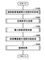
- FIG. 5 is a flowchart showing a schematic processing procedure of the switching process of the selected sub power storage device in the power supply system of the hybrid vehicle according to the embodiment of the present invention.
- 6 to 10 are flowcharts illustrating details of steps S100, S200, S300, S400, and S500 of FIG.
- the control device 30 can repeatedly execute the control processing procedure according to the flowcharts shown in FIGS. 5 to 10 at a predetermined cycle by executing a predetermined program stored in advance at a predetermined cycle. Thereby, the connection switching process of the sub power storage device in the power supply system of the hybrid vehicle according to the embodiment of the present invention can be realized.
- control device 30 executes a switching determination process for the selected sub power storage device.
- the following steps S200 to S500 are executed.
- steps S200 to S500 are substantially not executed.
- control device 30 executes pre-switching boost processing, and in step S300, power limit change processing is performed so that an excessive charge / discharge request is not generated for the power supply system during the connection switching period of the sub power storage device.
- step S400 control device 30 executes a connection switching process for actually switching the connection between selected sub power storage device BB and converter 12B, and after the completion, in step S500, a control process is performed to execute a return process to generate a new selected sub power storage device.
- the power supply by the device BB is started.
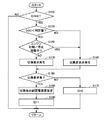
- FIG. 6 is a flowchart for explaining the details of the switching determination process (S100) of the selected sub power storage device in FIG.
- variable ID indicating the progress (status) of the connection switching process.
- control device 30 determines whether or not a switching request needs to be generated based on the state of charge (SOC) of selected sub power storage device BB. For example, the SOC of selected sub power storage device BB is compared with a predetermined determination value, and when the SOC is lower than the determination value, step S110 is determined as YES.
- SOC state of charge
- control device 30 proceeds to step S130 when step S120 is NO, that is, when the SOC of selected sub power storage device BB is lower than the determination value and neither the engine start process nor the stop process is executed.
- the process proceeds to generate a switching request for the selected sub power storage device BB.
- control device 30 proceeds to step S140.
- the switching request is not generated.
- control device 30 does not generate a switching request in step S140.
- step S105 is determined as YES, so that the switching determination process is executed again. As a result, even if SOC ⁇ determination value is satisfied during the execution of the stop process or the start process of the engine 4, the generation of the switching request is waited until the end of the process.
- Steps S110 to S180 are skipped.
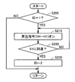
- FIG. 7 is a flowchart for explaining the details of the pre-switching boosting process (S200) shown in FIG.
- ID 1 and a switching request for selected sub power storage device BB is made and the switching process is started (YES in S205)
- control device 30 determines that power supply line PL2 is set in step S210.
- a boost command for converter 12A is generated so as to boost voltage VH to predetermined voltage V1.
- the predetermined voltage V1 is set to a voltage higher than the higher one of the output voltages of the main power storage device BA and the newly connected selected sub power storage device BB (for example, BB2).
- predetermined voltage V1 is set to control upper limit voltage VHmax that can be boosted by converter 12A, voltage VH at the time of the boost command is made higher than both output voltage of main power storage device BA and selected sub power storage device BB after switching. Can be surely high.
- predetermined voltage V1 is determined each time with a margin according to the output voltages of main power storage device BA and selected sub power storage device BB after switching. Also good.
- step S210 the control device 30 determines whether the voltage VH has reached the predetermined voltage V1 based on the detection value of the voltage sensor 13 in step S220. For example, when VH ⁇ V1 is maintained for a predetermined time, step S220 is determined as YES.
- the control device 30 advances the ID from 1 to 2.
- ID ⁇ 1 NO in S205
- the subsequent steps S210 to S230 are skipped.
- step S200 the control device 30 executes a power limit changing process as shown in FIG.
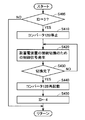
- FIG. 8 is a flowchart for explaining the details of the power limit change process (S300) shown in FIG.
- control device 30 starts temporary relaxation of the charge / discharge restriction of main power storage device BA in step S310. Specifically, the absolute values of input / output upper limit powers Win (M) and Wout (M) of main power storage device BA are temporarily increased.
- control device 30 gradually decreases the absolute values of input / output upper limit powers Win (S) and Wout (S) of selected sub power storage device BB. For example, Wout (S) and Win (S) are gradually decreased toward 0 according to a predetermined constant rate.
- ID 3 indicates a state in which the pre-switching boosting process and the power limit changing process have been completed and connection switching between sub power storage devices BB1 and BB2 and converter 12B can be started.
- control device 30 executes the sub power storage device connection switching process in step S400.
- FIG. 9 is a flowchart for explaining the details of the connection switching process (S400) of the sub power storage device shown in FIG.
- ID ⁇ 3 NO in S405
- the processes in subsequent steps S410 to S450 are skipped.
- control device 30 stops converter 12B as preparation for switching the connection of the sub power storage device in step S410. That is, in the converter 12B, the IGBT elements Q1, Q2 are forcibly turned off in response to the shutdown command. Then, in step S420, control device 30 generates a relay control signal for actually switching the connection of the sub power storage device. For example, in order to disconnect battery BB1 from converter 12B and to connect battery BB2 to converter 12B, relay control signals CONT4 and CONT6 are generated to turn off relays SR1 and SR1G, while relays SR2 and SR2G are turned on. Thus, relay control signals CONT5 and CONT7 are generated.
- control device 30 determines whether or not the relay connection switching instructed in step S420 has been completed.
- control device 30 restarts converter 12B and starts a switching operation in step S440, and advances ID from 3 to 4 in step S450.
- control device 30 executes the return process at step S500.
- FIG. 10 is a flowchart for explaining the details of the return processing (S500) shown in FIG.
- control device 30 ends temporary relaxation of the charge / discharge restriction of main power storage device BA started in step S310 (FIG. 7) in step S510. .
- Wout (M) and Win (M) basically return to the values before the start of the switching process of the selected sub power storage device BB.
- control device 30 converts input / output upper limit power Win (S), Wout (S) of selected sub power storage device BB, which has been reduced to 0 by power limiting processing (step S300), to a new selected sub power storage device (for example, The battery BB2) is gradually raised to the values of Win and Wout.
- control device 30 confirms whether or not input / output upper limit power Win (S), Wout (S) has returned to the values of Win, Wout of the new selected sub power storage device BB in step S530. During the period until the return is completed (NO in S530), step S520 is repeatedly executed, and the input / output upper limit powers Win (S) and Wout (S) gradually increase at a constant rate.
- control device 30 When the restoration of the input / output upper limit powers Win (S) and Wout (S) is completed (when YES is determined in S530), the control device 30 returns the ID to 0 again in step S540. Thereby, in the power supply system, a state in which normal power supply and power recovery by main power storage device BA and new selected sub power storage device BB are possible is reproduced.
- control device 30 advances the process to step S550, and turns off the boost command generated in step S210 (FIG. 6).
- the voltage command value of power supply line PL2 is also a normal value set according to the state of motor generators MG1, MG2.
- step S570 the switching determination process in step S100 is executed at a predetermined cycle, so that the switching process of the selected sub power storage device is started again as necessary.
- ID 0 is maintained depending on the situation.
- the configuration can be made such that the switching process of the selected sub power storage device from the second time onward can be executed.
- FIG. 11 shows operation waveforms in the switching process of the selected sub power storage device in the power supply system of the hybrid vehicle according to the embodiment of the present invention described with reference to FIGS.
- step S200 the pre-switching boosting process (step S200) is executed, and the voltage VH of the feed line PL2 is raised toward the predetermined voltage V1 by the converter 12A.
- the ID is changed from 1 to 2.
- the power limit changing process (S300) is executed, and charging / discharging of the main power storage device BA is temporarily alleviated. That is, a temporary increase in the absolute values of the input / output upper limit powers Win (M) and Wout (M) is started. Further, the input / output upper limit powers Win (S) and Wout (S) of the selected sub power storage device BB are gradually decreased at a constant rate toward zero. In this period, converter 12B is controlled to stop charging / discharging of currently selected sub power storage device (battery BB1). Alternatively, converter 12B may shut down from time t1.
- the ID is changed from 2 to 3.
- relay connection switching processing is completed and battery BB2 as a new selected sub power storage device is connected to converter 12B, converter 12B is activated again.
- the ID is changed from 3 to 4 at time t4.
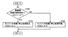
- FIG. 13 shows a flowchart for explaining engine start / stop restriction according to the flag RQES.
- control device 30 determines whether or not there is an engine stop request or a start request in step S800.
- the engine stop request and the start request are based on the comparison between the input / output upper limit power in the entire power supply system and the total required power Pttl, or for the purpose of component protection, for example, the engine 4 or the motor generator MG1. It is generated for the purpose of suppressing the excessive increase of the rotation speed.
- control device 30 proceeds to step S810 to determine whether engine 4 start request or stop request is for component protection. Determine.
- control device 30 When it is not a stop request or a start request for parts protection (NO determination in S810), control device 30 further permits engine start / stop processing based on flag RQES in step S820. Determine whether to prohibit. Specifically, when flag RQES is on (YES in S820), that is, during the sub power storage device switching process, start / stop process of engine 4 is prohibited in step S830. In this case, even if a start request or a stop request for engine 4 is generated, generation of an engine start command or a stop command by travel control unit 250 (FIG. 4) is caused by flag RQES when the sub power storage device switching process ends. Wait until is turned off.
- control device 30 proceeds to step S840 to respond to the engine stop request or the engine start request, or to start engine 4 or Allow stop processing to start.
- control device 30 does not depend on flag RQES, that is, the switching process of the sub power storage device. Even during the process, the process proceeds to step S840 to permit the engine start process and the engine stop process. That is, the engine stop request or engine start request for parts protection is preferentially permitted.
- FIG. 14 is a functional block diagram illustrating functional parts for switching processing of the selected sub power storage device and engine start / stop restriction in the control configuration of the hybrid vehicle according to the embodiment of the present invention.
- Each functional block shown in FIG. 14 is realized by software processing by the control device 30 by execution of a predetermined program or a dedicated electronic circuit (hardware processing).
- switching determination unit 100 receives SOC (BB1) and SOC (BB2) indicating the state of charge of batteries BB1 and BB2, and determines that SOC of selected sub power storage device BB currently in use is a predetermined determination. Determine if the value has fallen below the value.
- the switching determination unit 100 executes the determination process at a predetermined cycle, and the ID changes from 0 to 1 when the selected sub power storage device needs to be switched. Let Thereby, a switching request for the selected sub power storage device is generated. That is, the function of the switching determination unit 100 corresponds to the process of step S110 in FIG.
- the battery switching prohibition unit 210 Based on the flag STPEG indicating that the engine stop process is being performed and the flag STREG indicating that the engine start process is being performed, the battery switching prohibition unit 210 performs the switching determination unit 100 during the engine start process and the engine stop process. On the other hand, a flag FINH for prohibiting the generation of the switching request is output. Specifically, the prohibition flag FINH is turned on when one of the flags STREG and STPEG is on, while the prohibition flag FINH is turned off when both the flags STREG and STPEG are off.
- Converter control unit 200 generates control signals PWUA and PWDA for converter 12A based on voltages VH and VLA and voltage command value VHref so that voltage VH of power supply line PL2 becomes voltage command value VHref.
- the power limiting unit 120 sets the input / output upper limit power Win (S), Wout (S) of the selected sub power storage device BB.
- the input / output upper limit powers Win (S) and Wout (S) are the SOC (SOC (BB1) or SOC (BB2)), battery temperature (TBB1 or TBB2), and output of the battery selected as the selected sub power storage device BB. It is set based on the voltage (VB1 or VB2).
- the ID is changed from 2 to 3.
- power limiting unit 120 changes input / output upper limit power Win (S), Wout (S) to Win of new selected sub power storage device BB after switching. , Win to a value corresponding to Win.
- the ID is changed from 4 to 0.
- the power limiting unit 120 performs the processing of steps S320 to S340 in FIG. 8, the processing of steps S520 to S540 in FIG. 10, and the “first power limiting unit” and “second power limiting unit” of the present invention. The function is realized.
- the power limiting unit 130 sets the input / output upper limit power Win (M) and Wout (M) of the main power storage device BA.
- input / output upper limit powers Win (M) and Wout (M) are set based on SOC (BA) of main power storage device BA, battery temperature TA, and output voltage VA.
- the power limiting unit 130 implements the processing of step S310 of FIG. 8 and step S510 of FIG. 10 and the function of the “third power limiting unit” of the present invention.
- Relay control signals CONT4 to CONT7 are generated. For example, when switching selected sub power storage device BB from battery BB1 to battery BB2, relay control signals CONT4 to CONT7 are generated such that relays SR1 and SR1G are turned off while relays SR2 and SR2G are turned on.
- the shutdown command is stopped and the converter 12B is restarted, and the ID is changed from 3 to 4.
- connection switching control unit 140 corresponds to the processing in step S400 in FIG. 5 (S405 to S450 in FIG. 9).
- the protection control unit 215 generates an engine start / stop request (not shown) for component protection based on the rotation speed of the rotating elements (for example, the motor generator MG1, the engine 4, etc.) connected to the power split mechanism 3. At the same time, a flag PRT indicating an engine start / stop request for protecting parts is turned on.
- steps S810 to S840 in FIG. 13 can be executed by the travel control unit 250 (FIG. 4) based on the flags PRT and RQES.
- the start processing and the stop processing of the internal combustion engine are prohibited during the connection switching processing of the sub power storage device, and the internal combustion engine
- the execution of the connection switching process of the sub power storage device during the start process or the stop process of can be prohibited. Therefore, during the connection switching process of the sub power storage device, it is possible to avoid fluctuations in the vehicle drive power that can be output due to the power input / output due to the engine start / stop process. (Drivability) can be prevented from being adversely affected.
- the input / output upper limit powers Win (S) and Wout (S) of the selected sub power storage device BB are appropriately limited. It can avoid being requested.
- the connection switching process of the sub power storage devices at the time of switching the selected sub power storage device is executed appropriately and smoothly. Is possible.
Landscapes
- Engineering & Computer Science (AREA)
- Transportation (AREA)
- Mechanical Engineering (AREA)
- Chemical & Material Sciences (AREA)
- Combustion & Propulsion (AREA)
- Power Engineering (AREA)
- Sustainable Development (AREA)
- Sustainable Energy (AREA)
- Life Sciences & Earth Sciences (AREA)
- Automation & Control Theory (AREA)
- Electric Propulsion And Braking For Vehicles (AREA)
- Hybrid Electric Vehicles (AREA)
- Control Of Vehicle Engines Or Engines For Specific Uses (AREA)
Abstract
Description
好ましくは、切換制御装置は、昇圧指示部と、第1の電力制限部と、接続切換制御部と、第2の電力制限部とをさらに含む。昇圧指示部は、切換要求が発生されたときに、給電ラインの電圧を、主蓄電装置の出力電圧および切換後に第2の電圧変換器と接続される副蓄電装置の出力電圧よりも高い第1の電圧とするように第1の電圧変換器に指示するように構成される。第1の電力制限部は、給電ラインの電圧が第1の電圧に達した後に、選択副蓄電装置による入出力電力上限値を徐々に零まで減少させるように構成される。接続切換制御部は、第1の電力制限部によって入出力電力上限値が零に設定されたときに、複数の副蓄電装置および第2の電圧変換器の間の接続を切換えるように構成される。第2の電力制限部は、接続切換制御部により複数の副蓄電装置および第2の電圧変換器の間の接続が切換えられた後に、第2の電圧変換器と新たに接続された副蓄電装置の充電状態に対応する値まで、入出力電力上限値を徐々に上昇させるように構成される。
また好ましくは、制御方法は、切換要求が発生されたときに、給電ラインの電圧を、主蓄電装置の出力電圧および切換後に第2の電圧変換器と接続される副蓄電装置の出力電圧よりも高い第1の電圧とするように第1の電圧変換器に指示するステップと、給電ラインの電圧が第1の電圧に達した後に、選択副蓄電装置による入出力電力上限値を徐々に零まで減少させるステップと、減少させるステップによって入出力電力上限値が零に設定されたときに、複数の副蓄電装置と第2の電圧変換器との間の接続を切換えるステップと、切換えるステップにより複数の副蓄電装置と第2の電圧変換器との間の接続が切換えられた後に、第2の電圧変換器と新たに接続された副蓄電装置の充電状態に対応する値まで、入出力電力上限値を徐々に上昇させるステップとをさらに備える。
このようにすると、第2の電圧変換器と副蓄電装置との接続切換の際には、主蓄電装置の出力電圧および新たに使用する副蓄電装置の出力電圧のいずれよりも高い第1の電圧まで給電ラインを昇圧した後に、新たに使用する副蓄電装置を第2の電圧変換器と接続することができる。これにより、給電ラインを介して、新たに使用する副蓄電装置からの短絡経路が形成されることを防止できる。また、副蓄電装置の接続切換前に副蓄電装置の入出力電力上限値を絞るとともに、接続切換完了後に当該入出力電力上限値を徐々に復帰させるので、接続切換のため副蓄電装置に対する電力入出力が不能である期間において、電源システムに対して過度の充放電電力が要求されることを防止できる。
図1を参照して、ハイブリッド車両1は、蓄電装置であるバッテリBA,BB1,BB2と、接続部39A,39Bと、コンバータ12A,12Bと、平滑用コンデンサC1,C2,CHと、電圧センサ10A,10B1,10B2,13,21A,21Bと、温度センサ11A,11B1,11B2と、電流センサ9A,9B1,9B2と、給電ラインPL2と、インバータ14,22と、モータジェネレータMG1,MG2と、車輪2と、動力分割機構3と、エンジン4と、制御装置30とを含む。
制御装置30は、これらの測定値に基づいて、SOC(State of Charge)に代表されるバッテリBAの状態を監視する。
なお、バッテリBA,BB1,BB2としては、たとえば、鉛蓄電池、ニッケル水素電池、リチウムイオン電池等の二次電池や、電気二重層コンデンサ等の大容量キャパシタなどを用いることができる。
図2を参照して、インバータ14は、U相アーム15と、V相アーム16と、W相アーム17とを含む。U相アーム15、V相アーム16、およびW相アーム17は、給電ラインPL2と接地ラインSL2との間に並列に接続される。
図3を参照して、コンバータ12Aは、一方端が電源ラインPL1Aに接続されるリアクトルL1と、給電ラインPL2と接地ラインSL2との間に直列に接続されるIGBT素子Q1,Q2と、それぞれの逆並列ダイオードD1,D2とを含む。
Claims (10)
- [規則91に基づく訂正 10.02.2010]
車両駆動パワーを発生するモータ(MG2)と、
前記モータとは独立に車両駆動パワーを出力可能に構成された内燃機関(4)と、
主蓄電装置(BA)と、
前記モータを駆動制御するインバータ(22)に給電を行う給電ライン(PL2)と、
前記給電ラインと前記主蓄電装置との間に設けられ、双方向の電圧変換を行うように構成された第1の電圧変換器(12A)と、
互いに並列に設けられた複数の副蓄電装置(BB1,BB2)と、
前記複数の副蓄電装置と前記給電ラインとの間に設けられ、前記複数の副蓄電装置のうちの1つと前記給電ラインの間で双方向の電圧変換を行うように構成された第2の電圧変換器(12B)と、
前記複数の副蓄電装置と前記第2の電圧変換器との間に設けられ、前記複数の副蓄電装置のうちの選択副蓄電装置(BB)を選択的に前記第2の電圧変換器と接続するように構成された接続部(39B)と、
前記複数の副蓄電装置と前記第2の電圧変換器との間の選択的な接続を制御するように構成された切換制御装置(30)と、
ハイブリッド車両の全体要求パワー(Pttl)を、前記モータの出力パワーと、前記内燃機関の出力パワーとに分配する走行制御部(250)とを備え、
前記走行制御部は、前記複数の副蓄電装置と前記第2の電圧変換器との間の接続切換処理中には、停止状態の前記内燃機関の始動処理および作動状態の前記内燃機関の停止処理を禁止する、ハイブリッド車両。 - 前記内燃機関(4)の出力変化により回転速度が変化される回転要素(MG1)と、
前記回転要素の過回転を抑制するために前記内燃機関の始動要求および停止要求の一方を生成する保護制御部(215)とをさらに備え、
前記走行制御部(250)は、前記保護制御部によって前記始動要求または前記停止要求が生成されたときには、前記接続切換処理中であるか否かにかかわらず前記内燃機関の前記始動処理または前記停止処理を許可する、請求の範囲第1項に記載のハイブリッド車両。 - 前記切換制御装置(30)は、
使用中の前記選択副蓄電装置の残存容量(SOC)の充電状態に基づいて、前記選択副蓄電装置の切換要求の発生要否を判定するように構成された切換判定部(100)と、
前記内燃機関が前記始動処理中または前記停止処理中であるときに、前記切換要求を発生しないように前記切換判定部に指示するように構成された切換禁止部(210)とを含む、請求の範囲第1項に記載のハイブリッド車両。 - [規則91に基づく訂正 10.02.2010]
車両駆動パワーを発生するモータ(MG2)および前記モータとは独立に車両駆動パワーを出力可能に構成された内燃機関(4)を搭載したハイブリッド車両(1)であって、
主蓄電装置(BA)と、
前記モータを駆動制御するインバータ(22)に給電を行う給電ライン(PL2)と、
前記給電ラインと前記主蓄電装置との間に設けられ、双方向の電圧変換を行うように構成された第1の電圧変換器(12A)と、
互いに並列に設けられた複数の副蓄電装置(BB1,BB2)と、
前記複数の副蓄電装置と前記給電ラインとの間に設けられ、前記複数の副蓄電装置のうちの1つと前記給電ラインの間で双方向の電圧変換を行うように構成された第2の電圧変換器(12B)と、
前記複数の副蓄電装置と前記第2の電圧変換器との間に設けられ、前記複数の副蓄電装置のうちの選択副蓄電装置(BB)を選択的に前記第2の電圧変換器と接続するように構成された接続部(39B)と、
前記複数の副蓄電装置と前記第2の電圧変換器との間の選択的な接続を制御するように構成された切換制御装置(30)とを備え、
前記切換制御装置は、
使用中の前記選択副蓄電装置の残存容量(SOC)の充電状態に基づいて、前記選択副蓄電装置の切換要求の発生要否を判定する切換判定部(100)と、
前記内燃機関が始動処理中または停止処理中であるときに、前記選択副蓄電装置の切換要求を発生しないように前記切換判定部に指示する切換禁止部(210)とを含む、ハイブリッド車両。 - [規則91に基づく訂正 10.02.2010]
前記切換制御装置は、
前記切換要求が発生されたときに、前記給電ラインの電圧(VH)を、前記主蓄電装置の出力電圧および切換後に前記第2の電圧変換器と接続される副蓄電装置の出力電圧よりも高い第1の電圧(V1)とするように前記第1の電圧変換器に指示するように構成された昇圧指示部(110)と、
前記給電ラインの電圧が前記第1の電圧に達した後に、前記選択副蓄電装置による入出力電力上限値(Win(S),Wout(S))を徐々に零まで減少させるように構成された第1の電力制限部(120)と、
前記第1の電力制限部によって前記入出力電力上限値が零に設定されたときに、前記複数の副蓄電装置および前記第2の電圧変換器の間の接続を切換えるように構成された接続切換制御部(140)と、
前記接続切換制御部により複数の副蓄電装置および前記第2の電圧変換器の間の接続が切換えられた後に、前記第2の電圧変換器と新たに接続された副蓄電装置の充電状態に対応する値まで、前記入出力電力上限値を徐々に上昇させるように構成された第2の電力制限部(120)とをさらに含む、請求の範囲第3項または第4項に記載のハイブリッド車両。 - [規則91に基づく訂正 10.02.2010]
ハイブリッド車両の制御方法であって、
前記ハイブリッド車両は、
車両駆動パワーを発生するモータ(MG2)と、
前記モータとは独立に車両駆動パワーを出力可能に構成された内燃機関(4)と、
主蓄電装置(BA)と、
前記モータを駆動制御するインバータ(22)に給電を行う給電ライン(PL2)と、
前記給電ラインと前記主蓄電装置との間に設けられ、双方向の電圧変換を行うように構成された第1の電圧変換器(12A)と、
互いに並列に設けられた複数の副蓄電装置(BB1,BB2)と、
前記複数の副蓄電装置と前記給電ラインとの間に設けられ、前記複数の副蓄電装置のうちの1つと前記給電ラインの間で双方向の電圧変換を行うように構成された第2の電圧変換器(12B)と、
前記複数の副蓄電装置と前記第2の電圧変換器との間に設けられ、前記複数の副蓄電装置のうちの選択された副蓄電装置(BB)を選択的に前記第2の電圧変換器と接続するように構成された接続部(39B)と、
前記複数の副蓄電装置と前記第2の電圧変換器との間の選択的な接続を制御するように構成された切換制御装置(30)と、
前記ハイブリッド車両の全体要求パワー(Pttl)を、前記モータの出力パワーと、前記内燃機関の出力パワーとに分配する走行制御部(250)とを備え、
前記制御方法は、
前記複数の副蓄電装置と前記第2の電圧変換器との間の接続切換処理中であるか否かを判定するステップ(S700)と、
前記接続切換処理中において、停止状態の前記内燃機関の始動処理および作動状態の前記内燃機関の停止処理を禁止するステップ(S820)とを備える、ハイブリッド車両の制御方法。 - [規則91に基づく訂正 10.02.2010]
前記ハイブリッド車両は、
前記内燃機関(4)の出力変化により回転速度が変化される回転要素(MG1)と、
前記回転要素の過回転を抑制するために前記内燃機関の始動要求および停止要求の一方を生成する保護制御部(215)とをさらに備え、
前記制御方法は、
前記保護制御部によって前記始動要求または前記停止要求が生成されたときには、前記接続切換処理中であるか否かにかかわらず前記内燃機関の前記始動処理または前記停止処理を許可するステップ(S810)をさらに備える、請求の範囲第6項に記載のハイブリッド車両の制御方法。 - 使用中の選択副蓄電装置の残存容量(SOC)の充電状態に基づいて、前記選択副蓄電装置の切換要求の発生要否を判定するステップ(S110)と、
前記内燃機関が前記始動処理中または前記停止処理中であるときに、前記選択副蓄電装置の充電状態にかかわらず前記切換要求を発生しないように指示するステップ(S120)とをさらに備える、請求の範囲第6項に記載のハイブリッド車両の制御方法。 - [規則91に基づく訂正 10.02.2010]
ハイブリッド車両の制御方法であって、
前記ハイブリッド車両は、
車両駆動パワーを発生するモータ(MG2)と、
前記モータとは独立に車両駆動パワーを出力可能に構成された内燃機関(4)と、
主蓄電装置(BA)と、
前記モータを駆動制御するインバータ(22)に給電を行う給電ライン(PL2)と、
前記給電ラインと前記主蓄電装置との間に設けられ、双方向の電圧変換を行うように構成された第1の電圧変換器(12A)と、
互いに並列に設けられた複数の副蓄電装置(BB1,BB2)と、
前記複数の副蓄電装置と前記給電ラインとの間に設けられ、前記複数の副蓄電装置のうちの1つと前記給電ラインの間で双方向の電圧変換を行うように構成された第2の電圧変換器(12B)と、
前記複数の副蓄電装置と前記第2の電圧変換器との間に設けられ、前記複数の副蓄電装置のうちの選択された副蓄電装置(BB)を選択的に前記第2の電圧変換器と接続するように構成された接続部(39B)と、
前記複数の副蓄電装置と前記第2の電圧変換器との間の選択的な接続を制御するように構成された切換制御装置(30)と、
前記制御方法は、
使用中の選択副蓄電装置の残存容量(SOC)の充電状態に基づいて、前記選択副蓄電装置の切換要求の発生要否を判定するステップ(S110)と、
前記内燃機関が始動処理中または停止処理中であるときに、前記選択副蓄電装置の充電状態にかかわらず前記切換要求を発生しないように指示するステップ(S120)とを備える、ハイブリッド車両の制御方法。 - [規則91に基づく訂正 10.02.2010]
前記切換要求が発生されたときに、前記給電ラインの電圧(VH)を、前記主蓄電装置の出力電圧および切換後に前記第2の電圧変換器と接続される副蓄電装置の出力電圧よりも高い第1の電圧(V1)とするように前記第1の電圧変換器に指示するステップ(S200)と、
前記給電ラインの電圧が前記第1の電圧に達した後に、前記選択副蓄電装置による入出力電力上限値(Win(S),Wout(S))を徐々に零まで減少させるステップ(S320~S340)と、
前記減少させるステップによって前記入出力電力上限値が零に設定されたときに、前記複数の副蓄電装置と前記第2の電圧変換器との間の接続を切換えるステップ(S400)と、
前記切換えるステップにより複数の副蓄電装置と前記第2の電圧変換器との間の接続が切換えられた後に、前記第2の電圧変換器と新たに接続された副蓄電装置の充電状態に対応する値まで、前記入出力電力上限値を徐々に上昇させるステップ(S520~S540)とをさらに備える、請求の範囲第8項または第9項に記載のハイブリッド車両の制御方法。
Priority Applications (5)
| Application Number | Priority Date | Filing Date | Title |
|---|---|---|---|
| EP08877750.3A EP2351677B1 (en) | 2008-10-31 | 2008-10-31 | Hybrid vehicle and method for controlling the same |
| CN2008801316856A CN102196954B (zh) | 2008-10-31 | 2008-10-31 | 混合动力车辆及其控制方法 |
| US13/003,727 US8571733B2 (en) | 2008-10-31 | 2008-10-31 | Hybrid vehicle and method for controlling the same |
| PCT/JP2008/069861 WO2010050039A1 (ja) | 2008-10-31 | 2008-10-31 | ハイブリッド車両およびその制御方法 |
| JP2010535580A JP5099229B2 (ja) | 2008-10-31 | 2008-10-31 | ハイブリッド車両およびその制御方法 |
Applications Claiming Priority (1)
| Application Number | Priority Date | Filing Date | Title |
|---|---|---|---|
| PCT/JP2008/069861 WO2010050039A1 (ja) | 2008-10-31 | 2008-10-31 | ハイブリッド車両およびその制御方法 |
Publications (1)
| Publication Number | Publication Date |
|---|---|
| WO2010050039A1 true WO2010050039A1 (ja) | 2010-05-06 |
Family
ID=42128417
Family Applications (1)
| Application Number | Title | Priority Date | Filing Date |
|---|---|---|---|
| PCT/JP2008/069861 WO2010050039A1 (ja) | 2008-10-31 | 2008-10-31 | ハイブリッド車両およびその制御方法 |
Country Status (5)
| Country | Link |
|---|---|
| US (1) | US8571733B2 (ja) |
| EP (1) | EP2351677B1 (ja) |
| JP (1) | JP5099229B2 (ja) |
| CN (1) | CN102196954B (ja) |
| WO (1) | WO2010050039A1 (ja) |
Families Citing this family (23)
| Publication number | Priority date | Publication date | Assignee | Title |
|---|---|---|---|---|
| US8077483B2 (en) | 2007-04-06 | 2011-12-13 | Power Integrations, Inc. | Method and apparatus for sensing multiple voltage values from a single terminal of a power converter controller |
| US8077486B2 (en) | 2007-04-06 | 2011-12-13 | Power Integrations, Inc. | Method and apparatus for power converter fault condition detection |
| US8527126B2 (en) * | 2008-10-31 | 2013-09-03 | Toyota Jidosha Kabushiki Kaisha | Power supply system for electrically powered vehicle and method for controlling the same |
| US8538616B2 (en) * | 2008-10-31 | 2013-09-17 | Toyota Jidosha Kabushiki Kaisha | Power supply system for electrically powered vehicle, electrically powered vehicle, and method for controlling the same |
| US8793041B2 (en) * | 2008-10-31 | 2014-07-29 | Toyota Jidosha Kabushiki Kaisha | Electric powered vehicle and control method for the same |
| CN102449873A (zh) | 2009-04-01 | 2012-05-09 | 伊格皮切尔科技有限责任公司 | 混合能量存储系统、包括该存储系统的可再生能量系统及其使用方法 |
| JP5152408B2 (ja) | 2009-06-10 | 2013-02-27 | トヨタ自動車株式会社 | ハイブリッド車両およびその制御方法 |
| KR101297150B1 (ko) * | 2012-01-12 | 2013-08-21 | 주진관 | 이차전지를 이용한 전원장치의 충방전 전환장치 |
| US10046646B2 (en) * | 2013-09-06 | 2018-08-14 | Samsung Sdi Co., Ltd. | Power conversion system for electric vehicles |
| US10202042B2 (en) * | 2013-10-04 | 2019-02-12 | Samsung Sdi Co., Ltd. | Electric vehicle power conversion system |
| FR3015804B1 (fr) * | 2013-12-20 | 2016-01-29 | Valeo Sys Controle Moteur Sas | Systeme d'entrainement, procede de commande d'un onduleur et programme d'ordinateur associe |
| DE102014016620B4 (de) * | 2014-10-24 | 2021-08-26 | Audi Ag | Verfahren zum Betrieb einer Energiespeichereinrichtung in einem Kraftfahrzeug und Kraftfahrzeug |
| JP6252519B2 (ja) * | 2015-03-06 | 2017-12-27 | トヨタ自動車株式会社 | ハイブリッド車の制御装置 |
| KR101875996B1 (ko) * | 2015-06-17 | 2018-07-06 | 현대자동차주식회사 | 친환경 차량용 양방향 컨버터 제어 장치 및 방법 |
| US10020759B2 (en) * | 2015-08-04 | 2018-07-10 | The Boeing Company | Parallel modular converter architecture for efficient ground electric vehicles |
| CN105305580B (zh) * | 2015-10-09 | 2018-07-03 | 阳光电源股份有限公司 | 一种电机控制系统及其控制方法和控制器 |
| TWI633738B (zh) * | 2016-09-07 | 2018-08-21 | 華碩電腦股份有限公司 | 儲能單元充放電模組及其充放電方法 |
| US10518652B2 (en) * | 2017-05-24 | 2019-12-31 | Toyota Motor Engineering & Manufacturing North America, Inc. | Fuel cell vehicle with power modules |
| WO2019058821A1 (ja) * | 2017-09-22 | 2019-03-28 | 株式会社村田製作所 | 蓄電装置 |
| JP6888512B2 (ja) * | 2017-10-16 | 2021-06-16 | トヨタ自動車株式会社 | ハイブリッド自動車 |
| DE102018102211B3 (de) * | 2018-02-01 | 2019-09-19 | Dr. Ing. H.C. F. Porsche Aktiengesellschaft | Batteriesystem für ein batteriebetriebenes elektrisches Fahrzeug und Verfahren zum Nutzen einer Restreichweite eines solchen |
| US11211814B2 (en) * | 2018-04-23 | 2021-12-28 | Spiers New Technologies, Inc. | Circuitry to prevent lithium plating within a lithium ion battery |
| KR20220123861A (ko) * | 2021-03-02 | 2022-09-13 | 현대자동차주식회사 | 차량 및 그 제어 방법 |
Citations (6)
| Publication number | Priority date | Publication date | Assignee | Title |
|---|---|---|---|---|
| JP2003209969A (ja) | 2001-12-06 | 2003-07-25 | General Motors Corp <Gm> | 電動モータ電源管理システム |
| JP2007062589A (ja) * | 2005-08-31 | 2007-03-15 | Toyota Motor Corp | ハイブリッド型車両 |
| JP2007098981A (ja) * | 2005-09-30 | 2007-04-19 | Toyota Motor Corp | 車両用電源装置 |
| JP2008109840A (ja) | 2006-09-28 | 2008-05-08 | Toyota Motor Corp | 電源システムおよびそれを備えた車両、電源システムの制御方法ならびにその制御方法をコンピュータに実行させるためのプログラムを記録したコンピュータ読取可能な記録媒体 |
| JP2008154439A (ja) * | 2006-11-20 | 2008-07-03 | Toyota Motor Corp | 電源回路の制御装置 |
| JP2008167620A (ja) | 2007-01-04 | 2008-07-17 | Toyota Motor Corp | 車両の電源装置および車両 |
Family Cites Families (22)
| Publication number | Priority date | Publication date | Assignee | Title |
|---|---|---|---|---|
| US6047787A (en) | 1998-02-03 | 2000-04-11 | Ecostar Electric Drive Systems Llc | Voltage control method for an electric motor control system |
| JP3961721B2 (ja) * | 1999-07-05 | 2007-08-22 | 株式会社デンソー | ハイブリッド車の駆動装置 |
| JP3750608B2 (ja) * | 2002-01-23 | 2006-03-01 | トヨタ自動車株式会社 | 車両における蓄電装置の制御装置 |
| JP2004359032A (ja) | 2003-06-03 | 2004-12-24 | Sony Corp | 電動アシスト自転車及び電動車両 |
| JP4165481B2 (ja) | 2004-09-08 | 2008-10-15 | 三菱ふそうトラック・バス株式会社 | ハイブリッド電気自動車の制御装置 |
| JP4517984B2 (ja) | 2005-09-01 | 2010-08-04 | トヨタ自動車株式会社 | ハイブリッド自動車 |
| JP4715466B2 (ja) * | 2005-11-24 | 2011-07-06 | トヨタ自動車株式会社 | ハイブリッド自動車 |
| JP4514725B2 (ja) | 2006-03-31 | 2010-07-28 | ダイハツ工業株式会社 | 車両の走行動力切り替え制御方法 |
| JP4745879B2 (ja) * | 2006-04-06 | 2011-08-10 | 日立ビークルエナジー株式会社 | ハイブリッド車両制御システム、ハイブリッド車両制御方法及び車両用蓄電池制御システム |
| JP2008087516A (ja) * | 2006-09-29 | 2008-04-17 | Toyota Motor Corp | ハイブリッド車両およびハイブリッド車両の走行制御方法 |
| JP4840197B2 (ja) | 2007-03-06 | 2011-12-21 | トヨタ自動車株式会社 | 車両の電源装置および車両の電源装置の制御方法 |
| JP2010187423A (ja) * | 2007-04-25 | 2010-08-26 | Toyota Motor Corp | 車両の制御装置 |
| US8718847B2 (en) * | 2008-10-14 | 2014-05-06 | Toyota Jidosha Kabushiki Kaisha | Control apparatus and control method for hybrid vehicle |
| JP5099230B2 (ja) * | 2008-10-31 | 2012-12-19 | トヨタ自動車株式会社 | 電動車両の電源システムおよびその制御方法 |
| US8793041B2 (en) * | 2008-10-31 | 2014-07-29 | Toyota Jidosha Kabushiki Kaisha | Electric powered vehicle and control method for the same |
| US8538616B2 (en) * | 2008-10-31 | 2013-09-17 | Toyota Jidosha Kabushiki Kaisha | Power supply system for electrically powered vehicle, electrically powered vehicle, and method for controlling the same |
| US8571734B2 (en) * | 2008-10-31 | 2013-10-29 | Toyota Jidosha Kabushiki Kaisha | Power supply system for electrically powered vehicle and method for controlling the same |
| US8527126B2 (en) * | 2008-10-31 | 2013-09-03 | Toyota Jidosha Kabushiki Kaisha | Power supply system for electrically powered vehicle and method for controlling the same |
| JP5477030B2 (ja) * | 2009-05-22 | 2014-04-23 | 日産自動車株式会社 | 電動車両の制御装置 |
| WO2010143280A1 (ja) * | 2009-06-10 | 2010-12-16 | トヨタ自動車株式会社 | 電動車両および電動車両の制御方法 |
| US8583307B2 (en) * | 2009-06-10 | 2013-11-12 | Toyota Jidosha Kabushiki Kaisha | Power supply system for electrically powered vehicle and method for controlling the same |
| JP5152408B2 (ja) * | 2009-06-10 | 2013-02-27 | トヨタ自動車株式会社 | ハイブリッド車両およびその制御方法 |
-
2008
- 2008-10-31 WO PCT/JP2008/069861 patent/WO2010050039A1/ja active Application Filing
- 2008-10-31 EP EP08877750.3A patent/EP2351677B1/en active Active
- 2008-10-31 JP JP2010535580A patent/JP5099229B2/ja active Active
- 2008-10-31 CN CN2008801316856A patent/CN102196954B/zh active Active
- 2008-10-31 US US13/003,727 patent/US8571733B2/en active Active
Patent Citations (6)
| Publication number | Priority date | Publication date | Assignee | Title |
|---|---|---|---|---|
| JP2003209969A (ja) | 2001-12-06 | 2003-07-25 | General Motors Corp <Gm> | 電動モータ電源管理システム |
| JP2007062589A (ja) * | 2005-08-31 | 2007-03-15 | Toyota Motor Corp | ハイブリッド型車両 |
| JP2007098981A (ja) * | 2005-09-30 | 2007-04-19 | Toyota Motor Corp | 車両用電源装置 |
| JP2008109840A (ja) | 2006-09-28 | 2008-05-08 | Toyota Motor Corp | 電源システムおよびそれを備えた車両、電源システムの制御方法ならびにその制御方法をコンピュータに実行させるためのプログラムを記録したコンピュータ読取可能な記録媒体 |
| JP2008154439A (ja) * | 2006-11-20 | 2008-07-03 | Toyota Motor Corp | 電源回路の制御装置 |
| JP2008167620A (ja) | 2007-01-04 | 2008-07-17 | Toyota Motor Corp | 車両の電源装置および車両 |
Non-Patent Citations (1)
| Title |
|---|
| See also references of EP2351677A4 * |
Also Published As
| Publication number | Publication date |
|---|---|
| JPWO2010050039A1 (ja) | 2012-03-29 |
| EP2351677A1 (en) | 2011-08-03 |
| EP2351677A4 (en) | 2013-05-01 |
| JP5099229B2 (ja) | 2012-12-19 |
| CN102196954B (zh) | 2013-10-23 |
| US8571733B2 (en) | 2013-10-29 |
| EP2351677B1 (en) | 2016-05-04 |
| US20110178664A1 (en) | 2011-07-21 |
| CN102196954A (zh) | 2011-09-21 |
Similar Documents
| Publication | Publication Date | Title |
|---|---|---|
| JP5099229B2 (ja) | ハイブリッド車両およびその制御方法 | |
| JP5024454B2 (ja) | 電動車両の電源システムおよびその制御方法 | |
| JP5141772B2 (ja) | 電動車両の電源システムおよびその制御方法 | |
| JP5141773B2 (ja) | 電動車両および電動車両の制御方法 | |
| JP5152408B2 (ja) | ハイブリッド車両およびその制御方法 | |
| JP5099230B2 (ja) | 電動車両の電源システムおよびその制御方法 | |
| JP4798305B2 (ja) | 電動車両の電源システムおよびその制御方法 | |
| JP4888600B2 (ja) | 電動車両の電源システム、電動車両および電動車両の制御方法 | |
| JP5029784B2 (ja) | 電動車両および電動車両の制御方法 | |
| JP4743342B2 (ja) | 電動車両の電源システム、電動車両および電動車両の電源システムの制御方法 |
Legal Events
| Date | Code | Title | Description |
|---|---|---|---|
| WWE | Wipo information: entry into national phase |
Ref document number: 200880131685.6 Country of ref document: CN |
|
| 121 | Ep: the epo has been informed by wipo that ep was designated in this application |
Ref document number: 08877750 Country of ref document: EP Kind code of ref document: A1 |
|
| WWE | Wipo information: entry into national phase |
Ref document number: 13003727 Country of ref document: US |
|
| WWE | Wipo information: entry into national phase |
Ref document number: 2008877750 Country of ref document: EP |
|
| ENP | Entry into the national phase |
Ref document number: 2010535580 Country of ref document: JP Kind code of ref document: A |
|
| NENP | Non-entry into the national phase |
Ref country code: DE |