WO2010046983A1 - 粒子線治療装置 - Google Patents
粒子線治療装置 Download PDFInfo
- Publication number
- WO2010046983A1 WO2010046983A1 PCT/JP2008/069227 JP2008069227W WO2010046983A1 WO 2010046983 A1 WO2010046983 A1 WO 2010046983A1 JP 2008069227 W JP2008069227 W JP 2008069227W WO 2010046983 A1 WO2010046983 A1 WO 2010046983A1
- Authority
- WO
- WIPO (PCT)
- Prior art keywords
- particle beam
- detector ring
- detector
- therapy system
- ring
- Prior art date
- Legal status (The legal status is an assumption and is not a legal conclusion. Google has not performed a legal analysis and makes no representation as to the accuracy of the status listed.)
- Ceased
Links
Images







Classifications
-
- A—HUMAN NECESSITIES
- A61—MEDICAL OR VETERINARY SCIENCE; HYGIENE
- A61N—ELECTROTHERAPY; MAGNETOTHERAPY; RADIATION THERAPY; ULTRASOUND THERAPY
- A61N5/00—Radiation therapy
- A61N5/10—X-ray therapy; Gamma-ray therapy; Particle-irradiation therapy
-
- A—HUMAN NECESSITIES
- A61—MEDICAL OR VETERINARY SCIENCE; HYGIENE
- A61N—ELECTROTHERAPY; MAGNETOTHERAPY; RADIATION THERAPY; ULTRASOUND THERAPY
- A61N5/00—Radiation therapy
- A61N5/10—X-ray therapy; Gamma-ray therapy; Particle-irradiation therapy
- A61N5/1048—Monitoring, verifying, controlling systems and methods
- A61N5/1049—Monitoring, verifying, controlling systems and methods for verifying the position of the patient with respect to the radiation beam
- A61N2005/1052—Monitoring, verifying, controlling systems and methods for verifying the position of the patient with respect to the radiation beam using positron emission tomography [PET] single photon emission computer tomography [SPECT] imaging
-
- A—HUMAN NECESSITIES
- A61—MEDICAL OR VETERINARY SCIENCE; HYGIENE
- A61N—ELECTROTHERAPY; MAGNETOTHERAPY; RADIATION THERAPY; ULTRASOUND THERAPY
- A61N5/00—Radiation therapy
- A61N5/10—X-ray therapy; Gamma-ray therapy; Particle-irradiation therapy
- A61N2005/1085—X-ray therapy; Gamma-ray therapy; Particle-irradiation therapy characterised by the type of particles applied to the patient
- A61N2005/1087—Ions; Protons
Definitions
- the present invention relates to a particle beam therapy apparatus that performs treatment by irradiating a subject with a particle beam, and more particularly to a particle beam therapy apparatus that can monitor an irradiation region of a particle beam during therapy.
- the affected area of the subject may be irradiated with radiation.
- a particle beam therapy system using a particle beam has been developed (see, for example, Non-Patent Document 1).
- a conventional particle beam therapy system 51 includes a top plate 52 on which a subject M is placed, a particle beam source 53 that irradiates a particle beam, and annihilation ⁇ rays emitted from the body of the subject M.
- a first detector ring 54 and a second detector ring 55 for detecting a pair are included.
- the particle beam source 53 is disposed at a position where both detector rings 54 and 55 are sandwiched.
- the particle beam source 53 can go around the subject M around the body axis of the subject M. That is, the gap provided between the detector rings 54 and 55 serves as a path for the particle beam.
- the first detector ring 54 is configured by arranging block-shaped radiation detectors 61 in a ring shape.
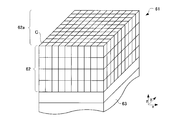
- the radiation detector 61 includes a scintillator 62 that converts radiation into fluorescence, and a photomultiplier tube (hereinafter referred to as a photodetector) 63 that detects fluorescence.
- the scintillator 62 has a rectangular parallelepiped scintillator crystal C arranged three-dimensionally, and the photodetector 63 can identify which scintillator crystal C the fluorescence is emitted from. That is, the radiation detector 61 can identify where the radiation is incident on the scintillator 62.
- the surface farthest from the photodetector 63 is referred to as an incident surface 62a for convenience.
- both detector rings 54 and 55 in the conventional particle beam therapy system 51 have a configuration in which radiation detectors 61 are simply arranged. That is, the scintillator 62 is configured to face the inner sides of both detector rings 54 and 55. Specifically, the scintillator 62 is configured to face the same position in the body axis direction A of the subject M.
- a particle beam beam is irradiated from the particle beam source 53 to the subject M placed on the top plate 52.
- the particle beam source 53 makes a round around the body axis of the subject M while irradiating the particle beam, and continues to irradiate the subject M with the particle beam while changing the irradiation angle.
- the particle beam loses energy in the body of the subject M.
- the nucleus located at the point where the particle beam lost energy is converted into a nuclide that causes ⁇ + decay. This nucleus undergoes ⁇ + decay and emits positrons.
- the generated positron hits an electron existing in the vicinity thereof and disappears.
- a pair of annihilation gamma ray pairs are generated that travel in directions opposite to each other by 180 °.
- This annihilation gamma ray pair penetrates the subject M and is detected by both detector rings 54 and 55.
- the conventional particle beam therapy system 51 estimates the point where the particle beam has lost energy by specifying the location where the annihilation ⁇ -ray pair is generated. At the point where the particle beam loses energy, the nearby cells are destroyed. In this way, it can be seen whether the particle beam accurately targets the lesioned part of the subject M.
- An annihilation gamma ray pair is an example of radiation derived from a particle beam.
- both annihilation gamma ray pairs must be detected. This is because the generation point of the annihilation ⁇ -ray pair is specified by obtaining a line connecting two points where the annihilation ⁇ -ray pair is detected (line of response: hereinafter referred to as LOR as appropriate).
- LOR line of response
- the conventional configuration has the following problems. That is, according to the conventional configuration, since it is necessary to provide a passage through which the particle beam source 53 passes, there is a problem that the detection sensitivity of the annihilation ⁇ -ray pair is not sufficient. That is, since there is a restriction that the position of the lesion area of the subject M in the body axis direction A and the particle beam source 53 must always be the same position, the detection sensitivity of the annihilation ⁇ -ray pair is sacrificed. Specifically, the detection sensitivity of the annihilation ⁇ -ray pair possessed by the detector ring strongly depends on the direction in which the annihilation ⁇ -ray pair is incident on the detector ring.
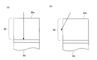
- the annihilation ⁇ ray pair is substantially perpendicular to the body axis direction A. Enter the first detector ring 54 at an angle. Then, as shown in FIG. 18A, one of the ⁇ -rays forming a pair of annihilation ⁇ -rays is incident from the incident surface 62 a of the scintillator 62 and travels toward the photodetector 63. Then, since the ⁇ -rays pass through the thick scintillator 62 before reaching the photodetector 63, the ⁇ -rays are surely converted into fluorescence, and the detection sensitivity of ⁇ -rays is high.
- both detector rings 54 and 55 of the particle beam therapy system 51 are provided avoiding a passage through which the particle beam source 53 passes. Since the position of the lesioned part of the subject M in the body axis direction A and the particle beam source 53 must always be at the same position regardless of the rotation of the particle beam source 53, the particles in the body axis direction A of the subject M The point where the line beam loses energy and the positions of both detector rings 54 and 55 are different from each other. That is, the annihilation gamma ray pair enters the first detector ring 54 from the oblique direction with respect to the body axis direction A. Then, as shown in FIG.
- ⁇ rays are not necessarily directed from the incident surface 62 a of the scintillator 62 toward the photodetector 63, but appear toward the side surface of the scintillator 62.
- some of the ⁇ -rays constituting the annihilation ⁇ -ray pair emerge from the side surface of the scintillator 62 while bypassing the central portion of the scintillator 62. Since such ⁇ rays are not converted into fluorescence, they are not detected by the radiation detector 61 after all.
- the thickness of the scintillator 62 on the path of the ⁇ -rays at the side end in the body axis direction A of the scintillator 62 is. Is lacking. This is because the ⁇ rays incident from the incident surface 62 a of the scintillator 62 bypass the central portion of the scintillator 62 and immediately go to the side surface of the scintillator 62.
- the ⁇ -rays emitted from the subject M in the particle beam therapy apparatus 51 are administered by a PET (Positoron Emission Tomography) device that administers to the subject M a radiopharmaceutical that releases annihilation ⁇ -ray pairs and
- the dose is very small, and the dose is, for example, about 1/1000 to 1/100 of that of a PET apparatus.
- two detector rings 54 and 55 are provided. Due to having two detector rings, the manufacturing cost of the particle beam therapy system 51 will increase. However, if a single detector ring is used, it is impossible to detect both ⁇ rays of the annihilation ⁇ ray pair.
- the detector ring is single.
- a radiation detector cannot be disposed at the position G. That is, it is not possible to detect annihilation ⁇ rays that travel while maintaining the position G. Instead, an annihilation gamma ray pair whose traveling direction does not follow the position G is detected. As shown in FIG. 19,
- one of the ⁇ rays of the annihilation ⁇ ray pair proceeds forward in the body axis direction A of the subject M, and the other of the ⁇ rays is the body axis direction of the subject M. Proceed backwards at A. It is impossible to detect such annihilation gamma ray pairs with a single detector ring. This is because the position of the radiation detector provided in the detector ring is the same in the body axis direction A of the subject M. After all, according to the conventional configuration, the detector ring cannot be made single.
- the present invention has been made in view of such circumstances, and an object of the present invention is to provide a particle beam therapy apparatus having a passage through which a particle beam passes and a point where a particle beam loses energy and a detector ring. It is an object to provide a particle beam therapy system having high detection sensitivity of an annihilation radiation pair even if the positions of these are different from each other in the body axis direction A of the subject M.
- the present invention has the following configuration. That is, in the particle beam therapy system according to the present invention, the scintillator having an incident surface that converts radiation into fluorescence and makes the radiation incident, the light guide that transmits and receives fluorescence, and the photodetector that detects fluorescence are in the same direction.
- a radiation detector is formed by stacking, and has a detector ring formed by arranging them in a ring shape.
- the detector ring tilting means for tilting the detector ring in a reversible manner with respect to the top plate, and detection is performed by the detector ring tilting means.
- the upper end of the device ring is inclined toward one direction of the top plate extending direction, and the lower end of the detector ring is inclined toward one direction opposite to the one direction of extending the top plate.
- the detector ring tilting means for tilting the detector ring in a reversible manner is provided.
- the detector ring is inclined with respect to the top plate. More specifically, the upper end of the detector ring is inclined toward one direction in which the top plate extends. Moreover, the lower end of the detector ring is inclined toward a direction opposite to one direction of the extending direction of the top plate.
- the particle beam source irradiates the particle beam toward the top plate. Therefore, the detector ring cannot be provided at a position that obstructs the progress of the particle beam.
- the detector ring can be inclined with respect to the top plate.
- the positional relationship between the detector ring and the particle beam can be changed. Therefore, according to the present invention, since the detector ring can be retracted from the particle beam by tilting the detector ring, a particle beam therapy apparatus capable of detecting annihilation radiation while irradiating the particle beam can be provided. It is.
- the annihilation radiation pair is detected by a single detector ring. Then, the detector ring detects an annihilation radiation pair generated inside. In other words, any pair of annihilation radiation will be incident on the detector ring at a substantially right angle. Therefore, the decrease in detection sensitivity described in FIG. 18 is suppressed.
- the upper end and the lower end of the detector ring are inclined so as to be opposite to each other.
- the particle beam therapy system can generate a map of the generation distribution of annihilation radiation pairs inside the detector ring opening.
- the lesion area of the subject is positioned inside the opening of the detector ring, which means that the annihilation radiation pair in the lesion area of the subject is also irradiated during particle irradiation.
- the occurrence distribution can be acquired.
- the manufacturing cost of the particle beam therapy apparatus strongly depends on the number of radiation detectors mounted on the detector ring, it is possible to provide a particle beam therapy system in which the manufacturing cost is significantly reduced compared to the conventional one. .
- the detector ring described above has an elliptical shape, and when the detector ring is tilted to a predetermined tilt angle, the radiation detector of the detector ring has a virtual direction in which the extending direction coincides with the top plate. It is more desirable if it is along a simple cylinder.
- the detector ring is vertically long in the vertical direction, it is more desirable.
- the detector ring has a vertically long elliptical shape in the vertical direction.
- the radiation detector included in the detector ring has a characteristic arrangement at a predetermined inclination angle. That is, the radiation detector is along a virtual cylinder. This is a cylinder in which the extending direction coincides with the top plate, and the shape when the cylinder is cut obliquely coincides with the elliptical shape of the detector ring.
- the array of radiation detectors provided in the detector ring is also along this virtual cylinder. As the detector ring is tilted, the upper and lower parts of the detector ring approach the top plate.
- the detector ring since the detector ring is vertically long in the vertical direction, the detector ring does not reliably interfere with the subject.
- the detector ring tilting means described above tilts the detector ring with the short axis of the elliptical detector ring as the central axis, and the short axis of the detector ring is independent of the inclination of the detector ring. It is more desirable if the position is constant.
- a particle beam therapy system capable of reliably imaging a lesioned part of a subject simply by aligning the lesioned part of the subject and the short axis of the detector ring. it can. That is, according to the above configuration, since the position of the minor axis of the detector ring is constant regardless of the inclination of the detector ring, the minor axis of the detector ring is always detected regardless of the inclination. It is located inside the opening. Therefore, according to the said structure, the particle beam therapy apparatus which can image the lesioned part of a subject more simply and reliably can be provided.
- the detector ring described above can also be configured to detect radiation derived from the particle beam while being tilted and moved by the detector ring tilting means.
- the detector ring described above may be configured to detect radiation derived from the particle beam while being tilted by the detector ring tilting means and maintaining the tilt angle.
- a particle beam therapy system with high detection sensitivity of annihilation radiation can be provided. It is expected that various nuclides are generated at the point where the particle beam loses energy in the body of the subject. The energy and properties of the radiation that they decay and emit vary. Some single photons can also be emitted, not annihilation gamma ray pairs. Such a single photon can be detected by the detector ring. This causes noise when attempting to image the action position of the particle beam using the annihilation gamma ray pair.
- the inclination of a detector ring can be made suitable including a direction.
- the detector ring may be configured to irradiate the particle beam while moving the detector ring in an inclined manner. It is good also as a structure which irradiates a particle beam with the angle maintained.
- the detector ring tilting means for tilting the detector ring in a reversible manner is provided.
- the detector ring is inclined with respect to the top plate.
- the particle beam source irradiates the particle beam toward the top plate.
- the detector ring can be inclined with respect to the top plate. Therefore, according to the present invention, since the detector ring can be retracted from the particle beam by tilting the detector ring, a particle beam therapy apparatus capable of detecting annihilation radiation while irradiating the particle beam can be provided. .
- the lesioned part of the subject can be positioned inside the opening of the detector ring even when the particle beam is irradiated. According to the present invention, it is not necessary to provide two detector rings as in the prior art, and an annihilation radiation pair can be sufficiently detected only by providing a single detector ring.
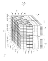
- FIG. 1 is a perspective view of a radiation detector according to Embodiment 1.
- FIG. It is a functional block diagram explaining the structure of the particle beam therapy apparatus which concerns on Example 1.
- FIG. It is a top view explaining the structure of the ellipse detector ring which concerns on Example 1.
- FIG. It is sectional drawing explaining the structure of the ellipse detector ring which concerns on Example 1.
- FIG. It is sectional drawing explaining the structure of the particle beam therapy apparatus which concerns on the structure of Example 1.
- FIG. It is sectional drawing explaining the structure of the particle beam therapy apparatus which concerns on the structure of Example 1.
- FIG. It is sectional drawing explaining the structure of the particle beam therapy apparatus which concerns on the structure of Example 1.
- FIG. It is sectional drawing explaining rotation of the particle beam source which concerns on Example 1.
- FIG. 3 is a flowchart for explaining the operation of the particle beam therapy system according to the first embodiment. It is a perspective view explaining the structure of the gantry which concerns on 1 modification of this invention. It is a perspective view explaining the structure of the top plate which concerns on 1 modification of this invention. It is a perspective view explaining the structure of the conventional particle beam therapy apparatus. It is a perspective view explaining the structure of the conventional particle beam therapy apparatus. It is sectional drawing explaining the structure of the conventional particle beam therapy apparatus. It is sectional drawing explaining the structure of the conventional particle beam therapy apparatus. It is sectional drawing explaining the structure of the conventional particle beam therapy apparatus. It is sectional drawing explaining the structure of the conventional particle beam therapy apparatus. It is sectional drawing explaining the structure of the conventional particle beam therapy apparatus. It is sectional drawing explaining the structure of the conventional particle beam therapy apparatus. It is sectional drawing explaining the structure of the conventional particle beam therapy apparatus.
- ⁇ rays are an example of the radiation of the present invention.
- FIG. 1 is a perspective view of the radiation detector according to the first embodiment.
- the radiation detector 1 according to the first embodiment includes a scintillator crystal layer 2D, a scintillator crystal layer 2C, a scintillator crystal layer 2B, and a scintillator crystal layer 2A, each of which is laminated in the z direction.
- the scintillator 2 formed in this way, a photomultiplier tube (hereinafter referred to as a photodetector) 3 provided on the lower surface of the scintillator 2 and having a position specifying function for detecting fluorescence emitted from the scintillator 2, A light guide 4 for transmitting and receiving fluorescence is provided at a position interposed between the light detector 3 and the light detector 3. Accordingly, each of the scintillator crystal layers is laminated in the direction toward the photodetector 3.
- the scintillator crystal layer 2 ⁇ / b> A serves as a radiation incident surface 14 in the scintillator 2.
- each scintillator crystal layer 2A, 2B, 2C, 2D is optically coupled, and a transmissive material t is provided between the respective layers.
- a thermosetting resin made of silicon resin can be used as the material of the transmission material t.
- the scintillator crystal layer 2A is a light-receiving portion for ⁇ rays emitted from a radioactive ray source, and 32 block scintillator crystals in the x direction and 32 in the y direction are based on the scintillator crystal a (1, 1). It is configured to be two-dimensionally arranged in an individual matrix.
- scintillator crystals a (1,1) to scintillator crystals a (1,32) are arranged in the y direction to form a scintillator crystal array, and 32 scintillator crystal arrays are arranged in the x direction to form a scintillator crystal layer.
- 2A is formed.
- the scintillator crystal layers 2B, 2C, and 2D also have 32 scintillator crystals in the x direction based on each of the scintillator crystals b (1,1), c (1,1), and d (1,1).
- the configuration is such that 32 pieces are arranged two-dimensionally in a matrix in the y direction.
- a transmission material t is also provided between adjacent scintillator crystals. Accordingly, each of the scintillator crystals is surrounded by the transmission material t.
- the thickness of the transmission material t is about 25 ⁇ m. Note that ⁇ rays correspond to the radiation of the present invention.
- the scintillator crystal layers 2A, 2B, 2C, 2D provided in the scintillator 2 are provided with a first reflector r extending in the x direction and a second reflector s extending in the y direction. Both the reflectors r and s are inserted in the gaps between the arranged scintillator crystals.
- the scintillator 2 is configured by three-dimensionally arranging scintillator crystals suitable for detecting ⁇ rays. That is, the scintillator crystal is composed of Lu 2 (1-X) Y 2X SiO 5 (hereinafter referred to as LYSO ) in which Ce is diffused. Each of the scintillator crystals is a rectangular parallelepiped having a length in the x direction of 1.45 mm, a width in the y direction of 1.45 mm, and a height in the z direction of 4.5 mm regardless of the scintillator crystal layer. Of the surfaces of the scintillator 2, four side surfaces in contact with the light guide 4 are covered with a reflection film (not shown). Moreover, the photodetector 3 is a multi-anode type, and can specify the positions of incident fluorescence x and y.
- the light guide 4 is provided to guide the fluorescence emitted from the scintillator 2 to the photodetector 3. Therefore, the light guide 4 is optically coupled to the scintillator 2 and the photodetector 3.
- a plurality of connection terminals 3p are provided on the bottom surface of the photodetector 3 away from the scintillator 2.
- the connection terminal 3p is connected to a bleeder unit 16 described later.
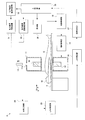
- FIG. 2 is a functional block diagram illustrating the configuration of the particle beam therapy system according to the first embodiment.
- the particle beam therapy system 9 according to the first embodiment includes a top plate 10 on which the subject M is placed, a gantry 11, and an ellipse detector ring 12 provided inside the gantry 11. I have.
- the ellipse detector ring 12 corresponds to the detector ring of the present invention.
- the gantry 11 is provided with a slit 11a for the purpose of securing a path for the particle beam.
- the details of the slit 11a will be described later.
- the particle beam therapy system 9 is further provided with each unit for acquiring a tomographic image of the subject M.
- the particle beam therapy system 9 receives a ⁇ -ray detection signal representing the detection position, detection intensity, and detection time of ⁇ -rays from the ellipse detector ring 12 and performs simultaneous counting of annihilation ⁇ -ray pairs.
- an image forming unit 27 for forming a radiation tomographic image of the region of interest.
- the particle beam therapy apparatus 9 which concerns on Example 1 is provided with the particle beam source 13 which irradiates a particle beam.
- the particle beam source 13 is driven by a particle beam source driving mechanism 31 and can turn around a base axis C along the body axis direction A of the subject M.
- the particle beam source drive mechanism 31 is controlled by a particle beam source drive control unit 32. Further, the particle irradiation of the particle beam source 13 is controlled by the particle beam source irradiation control unit 33.
- the particle beam source 13 is swung around the body axis of the subject M while the direction of the particle irradiation of the particle beam source 13 is changed. Specifically, the particle beam source 13 irradiates the particle beam in the direction toward the base axis C regardless of the turning movement. That is, the particle beam source 13 irradiates the particle beam toward one point belonging to the base axis C regardless of the turning movement. The particle beam irradiated from the particle beam source 13 is introduced into the gantry 11 by passing through the slit 11a.
- the particle beam therapy system 9 includes the tilt mechanism 14 that tilts the ellipse detector ring 12 and the tilt control unit 15 that controls the tilt mechanism 14.
- the tilt control unit corresponds to the detector ring tilting means of the present invention.
- the particle beam therapy system 9 includes a main control unit 35 that comprehensively controls various control units and a display unit 36 that displays a radiation tomographic image.
- the main control unit 35 is constituted by a CPU, and executes various programs, whereby the coincidence counting unit 24, the LOR specifying unit 25, the LOR correcting unit 26, the image forming unit 27, the particle beam source drive control unit 32, and the particles
- the radiation source irradiation control unit 33 is realized.
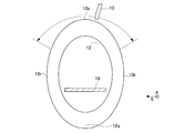
- the ellipse detector ring 12 has an elliptical elliptical plate 12a having an elliptical through hole at the center.
- the radiation detector 1 is arranged in an annular shape along the elliptical plate 12 a to form an elliptical detector ring 12. Therefore, the ellipse detector ring 12 has an elliptical opening 12b in the center. And all the incident surfaces which each radiation detector 1 has are arrange
- the ellipse detector ring 12 has an elliptical shape that is vertically long in the vertical direction, and P in the figure represents the short axis of the elliptical detector ring 12 that has an elliptical shape.
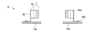
- FIG. 4 is a cross-sectional view of the ellipse detector ring 12 according to the first embodiment. This sectional view is a sectional view when the ellipse detector ring 12 is cut along the direction in which the opening extends.
- a bleeder unit 16 that supplies power to the radiation detector 1 is attached to the radiation detector 1, and the first radiation detector and the bleeder unit 16 are integrally held by an L-shaped holder 20.
- the holder 20 has a main plate 20a for fixing the bleeder unit 16 and a sub-plate 20b for fixing the holder 20 itself to the elliptical plate 12a.
- the bleeder unit 16 is fixed to the elliptical plate 12a via the holder 20.
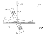
- FIG. 5 shows an initial state before using the particle beam therapy system 9 according to the configuration of the first embodiment.
- the ellipse detector ring 12 is not inclined, and the positions of the radiation detector 1 provided in the ellipse detector ring 12 in the body axis direction A of the subject M are all the same.
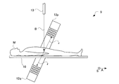
- the ellipse detector ring 12 has the upper end 12 p of the ellipse detector ring 12 facing forward in the body axis direction A of the subject M as shown in FIG. 6. Be inclined. Then, the lower end 12q of the ellipse detector ring 12 is inclined toward the rear in the body axis direction A of the subject M.
- the body axis direction A of the subject M coincides with the extending direction of the top plate 10 according to the first embodiment.
- the positional relationship between the particle beam source 13 and the ellipse detector ring 12 is changed from the initial state, and the ellipse detector ring 12 is on the path of the particle beam B irradiated by the particle beam source 13. not exist.
- the particle beam B irradiated from the particle beam source 13 bypasses the ellipse detector ring 12 and reaches the subject M.
- the upper end 12p of the ellipse detector ring 12 is inclined toward the front in the body axis direction A of the subject M. The inclination in this direction is referred to as the forward inclination for convenience.
- the particle beam is converted into an annihilation gamma ray pair r in the body of the subject M. Since the traveling directions of the ⁇ -rays constituting the annihilation ⁇ -ray pair are opposite to each other by 180 °, for example, one of the ⁇ -rays travels forward and above the top plate 10 and the other of the ⁇ -rays May travel to the rear and below the top plate 10. As described above, according to the configuration of the first embodiment, the ellipse detector ring 12 is inclined with respect to the particle beam, so that it is not necessary to prepare two detector rings as in the conventional configuration. The annihilation gamma ray pair can be detected.
- the annihilation ⁇ -ray pair r is incident on the detector ring at an angle close to a right angle. Since the ⁇ -ray pair r incident on the detector ring surely passes through the central part of the scintillator 2 of the radiation detector 1 because of such a configuration, the first embodiment is more effective than the conventional configuration. In the configuration of ⁇ , the detection sensitivity of ⁇ rays is higher.
- the ellipse detector ring 12 tilts the upper end 12 p of the ellipse detector ring 12 toward the rear in the body axis direction A of the subject M according to the control of the tilt control unit 15.
- the lower end 12q of the ellipse detector ring 12 is inclined toward the front in the body axis direction A of the subject M. In this way, the tilt control unit 15 can tilt in the opposite direction.
- the S / N ratio is better in the intermediate state between the state of FIG. 6 and the state of FIG. Furthermore, for example, it may be better when the tilt angle is in the initial state. If the tilt angle is in the initial state, the particle beam B does not reach the subject as shown in FIG. However, even when the tilt angle is in the initial state, the annihilation ⁇ -ray pair can be detected. That is, before irradiating the particle beam B from the particle beam source 13, the ellipse detector ring 12 is tilted, the particle beam B is irradiated in this state, and the irradiation of the particle beam B is stopped. The ellipse detector ring 12 can be configured to return to the initial position.
- the annihilation ⁇ -ray pair can be detected while irradiating the subject M with the particle beam B.
- the particle beam loses energy
- nuclides that emit annihilation gamma rays are generated.
- this does not immediately radiate annihilation gamma ray pairs. Therefore, if detection of the annihilation ⁇ -ray pair is started by returning the ellipse detector ring 12 to the initial position while the nuclide that emits the annihilation ⁇ -ray pair remains, the S / N ratio is good. In some cases, annihilation ⁇ -ray pairs can be detected with.
- the ellipse detector ring 12 is moved to a predetermined position and the annihilation gamma ray pair is detected, but the configuration of the first embodiment is not limited to this. That is, it is possible to adopt a configuration in which the annihilation ⁇ -ray pair is detected by irradiating the particle beam B while tilting the ellipse detector ring 12.
- the ellipse detector ring 12 when the ellipse detector ring 12 reaches a predetermined prohibition angle, irradiation of the particle beam B from the particle beam source 13 is prohibited.
- the ellipsoid detector ring 12 can be tilted and irradiated with the particle beam B to detect the annihilation ⁇ -ray pair.
- the short axis P of the ellipse detector ring 12 is shown.
- This short axis P is the central axis of the inclination of the ellipse detector ring 12. That is, the ellipse detector ring 12 is tilted while maintaining the position of the short axis P.
- the major axis of the ellipse detector ring 12 is inclined following the inclination of the ellipse detector ring 12.
- FIG. 8 is a cross-sectional view illustrating the turning of the particle beam source according to the first embodiment.
- the particle beam source 13 can turn around the body axis of the subject M by turning from the vertically upward position of the ellipse detector ring 12.
- the particle beam source 13 can make a round around the body axis of the subject M.
- the particle beam is not always irradiated during the turning movement.
- both end 12r in the body side direction A of the subject M in the ellipse detector ring 12 only rotates and does not move. That is, the effect of changing the position of the ellipse detector ring 12 by inclining the ellipse detector ring 12 becomes smaller as it approaches the both ends 12r in the body side direction A of the subject M.
- the particle beam source 13 When the particle beam source 13 is swung to the vicinity of the short axis P in the ellipse detector ring 12, the particle beam B emitted from the particle beam source 13 eventually interferes with the ellipse detector ring 12. Therefore, the particle beam source 13 is configured to irradiate the particle beam when the particle beam source 13 is swung around the major axis of the ellipse detector ring 12.
- the gantry 11 As the particle beam B turns, the gantry 11 is provided with a slit 11a. That is, as shown in FIG. 9, the gantry 11 is provided with a slit 11 a extending so as to go around the body axis of the subject M. The shape of the slit 11a coincides with the trajectory of the particle beam B that rotates.
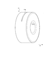
- FIG. 10 is a perspective view illustrating the ellipse detector ring according to the first embodiment.
- FIG. 10 shows a state where the ellipse detector ring 12 is tilted to the maximum angle.
- the side edge of the ellipse detector ring 12 is included in the surface of the virtual cylinder 40 whose extending direction coincides with the body axis direction A of the subject M.
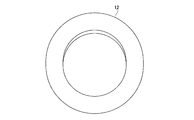
- the ellipse detector ring 12 has a perfect circular shape.
- the radiation detectors 1 arranged in the ellipse detector ring 12 are arranged along the shape of the ellipse detector ring 12, when the ellipse detector ring 12 is tilted to the maximum angle, ellipse detection is performed.
- Each of the radiation detectors 1 deployed in the instrument ring 12 will be along the cylinder 40 described above.
- the ellipse detector ring 12 does not interfere with the subject M.
- the upper part of the ellipse detector ring 12 descends and approaches the subject M.
- the operation of the particle beam therapy apparatus 9 includes a placement step S1 for placing the subject M on the top board 10, an inclination step S2 for inclining the ellipse detector ring 12, and a particle beam source 13.
- a placement step S1 for placing the subject M on the top board 10
- an inclination step S2 for inclining the ellipse detector ring 12
- a particle beam source 13 are provided with an irradiation step S3 for irradiating the subject M with the particle beam B and a detection step S4 for detecting annihilation ⁇ rays derived from the particle beam.
- the subject M is placed on the top board 10 (placement step S1). Then, the operator moves the table 10 forward and backward along the body axis direction A of the subject M so that the lesioned part of the subject M becomes the passing position of the particle beam B emitted from the particle beam source 13. Next, the operator instructs the ellipse detector ring 12, and the ellipse detector ring 12 is tilted to the tilt angle and tilt direction as instructed by the operator (tilt step S2). In the particle beam therapy apparatus 9, when the ellipse detector ring 12 reaches a predetermined inclination angle, the irradiation of the particle beam B is permitted and the apparatus waits until the operator gives an instruction.
- the particle beam B is irradiated from the particle source 13 (irradiation step S3). Then, the annihilation gamma ray pair derived from the particle beam B is detected by the ellipse detector ring 12 (detection step S4).
- the image forming unit 27 generates a distribution map of annihilation ⁇ rays detected from the subject M based on the detection data transmitted by the ellipse detector ring 12. This is displayed on the display unit 36, and the operator can confirm whether the particle beam B has reached the lesioned part accurately. In this way, the operation of the particle beam therapy system 9 according to the first embodiment is finished. In addition, you may perform above-mentioned inclination step S2 and irradiation step S3 simultaneously. That is, the ellipse detector ring 12 may be configured to irradiate the particle beam B while being tilted.
- An annihilation gamma ray pair generated inside the subject M is detected by one of the radiation detectors 1 provided in the ellipse detector ring 12.
- the ellipse detector ring 12 sends detection data indicating that ⁇ rays have been detected to the coincidence counting unit 24.
- the coincidence counting unit 24 when detection data derived from two different scintillator crystals are contained in a time window having a predetermined time width, it is assumed that this is due to an annihilation gamma ray pair, and this number of times is calculated. Count. This is the count number.
- the exit direction of the annihilation ⁇ -ray pair is determined.
- the detection data regarded as simultaneous by the coincidence counting unit 24 includes positional information indicating which scintillator crystal emits fluorescence.
- the LOR specifying unit 25 calculates an LOR (Line of Response) that is a line segment connecting the two scintillator crystals, and sends the LOR and the corresponding count number to the LOR correcting unit 26.
- the detection data transmitted by the ellipse detector ring 12 includes information on the tilt direction and tilt angle of the ellipse detector ring 12.
- correction for removing the influence of the inclination of the ellipse detector ring 12 is applied to the LOR.
- the relative positional relationship between the ellipse detector ring 12 and the subject M changes.
- LOR only indicates the relative position of the annihilation ⁇ ray pair generation position in the ellipse detector ring 12.
- the direction indicated by the LOR changes according to the inclination angle of the ellipse detector ring 12, so that it is not possible to specify where the annihilation ⁇ -rays are generated.
- the LOR is virtually tilted based on the tilt direction and tilt angle information of the ellipse detector ring 12 included in the detection data.
- the influence of the change in the inclination of the ellipse detector ring 12 is removed. Therefore, according to the configuration of the first embodiment, even when the ellipse detector ring 12 is inclined, the generation position of the annihilation ⁇ -ray pair can be specified.
- the corrected LOR and the corresponding count number are sent to the image forming unit 27.
- the image forming unit 27 maps the occurrence distribution of annihilation ⁇ -ray pairs on the tomographic plane of the subject M based on the corrected LOR and the corresponding count number.
- the tomographic image thus formed is displayed on the display unit 36. If the generation distribution of annihilation ⁇ -ray pairs is displayed, it is possible to monitor a site where the particle beam in the tomographic plane of the subject M has lost energy. In this way, it can be confirmed whether or not the particle beam in the particle beam therapy system 9 acts on the lesioned part of the subject M reliably.
- the tilt control unit 15 that tilts the ellipse detector ring 12 in a reversible manner is provided.
- the ellipse detector ring 12 is inclined with respect to the top plate 10. More specifically, the upper end 12 p of the ellipse detector ring 12 is inclined toward one direction in which the top plate 10 extends. Further, the lower end 12q of the ellipse detector ring 12 is inclined toward a direction opposite to one direction in which the top plate 10 extends.
- the particle beam source 13 irradiates the particle beam B toward the top plate 10. Therefore, the ellipse detector ring 12 cannot be provided at a position that obstructs the progression of the particle beam B.
- the ellipse detector ring 12 can be inclined with respect to the top plate 10. This also means that the positional relationship between the ellipse detector ring 12 and the particle beam B can be changed. Therefore, according to the first embodiment, since the ellipse detector ring 12 can be retracted from the particle beam B by tilting the ellipse detector ring 12, annihilation radiation can be detected while irradiating the particle beam B.
- the particle beam therapy apparatus 9 can be provided.
- the annihilation gamma ray pair is detected by a single ellipse detector ring 12. Then, the annihilation gamma ray pair generated inside the ellipse detector ring 12 is detected. In other words, any of the annihilation gamma ray pairs are incident on the single ellipse detector ring 12 at a substantially right angle. Therefore, the decrease in detection sensitivity described with reference to FIG. 18 is suppressed.
- the upper end 12p and the lower end 12q of the ellipse detector ring 12 are inclined so as to be directed in opposite directions.
- a predetermined area a lesion area of the subject M
- the particle beam therapy system 9 can generate a map of the generation distribution of annihilation gamma ray pairs in the opening of the ellipse detector ring 12.
- the lesion area of the subject M is positioned inside the opening of the ellipse detector ring 12, which means that the lesion area of the subject M is also irradiated while the particle beam is irradiated.
- the generation distribution of annihilation gamma ray pairs in the region can be acquired. That is, according to the configuration of the first embodiment, it is not necessary to provide two detector rings as in the prior art, and it is possible to sufficiently detect annihilation ⁇ -ray pairs simply by providing a single ellipse detector ring 12. . Since the manufacturing cost of the particle beam therapy apparatus 9 depends strongly on the number of radiation detectors 1 mounted on the ellipse detector ring 12, the particle beam therapy whose manufacturing cost is significantly reduced compared to the conventional one. A device 9 can be provided.
- the ellipse detector ring 12 has a vertically long elliptical shape in the vertical direction.
- the radiation detector 1 included in the ellipse detector ring 12 has a characteristic arrangement at a predetermined inclination angle. That is, the radiation detector 1 is along the virtual cylinder 40. This is because the shape when the cylinder 40 whose extending direction coincides with the top 10 is cut obliquely is the same as the elliptical shape of the ellipse detector ring 12.
- the arrangement of the radiation detectors 1 provided in the ellipse detector ring 12 is also arranged along the virtual cylinder 40.
- the ellipse detector ring 12 As the ellipse detector ring 12 is tilted, the upper and lower parts of the ellipse detector ring 12 approach the top plate 10. However, according to the configuration of the first embodiment, since the ellipse detector ring 12 is vertically long in the vertical direction, the ellipse detector ring 12 does not reliably interfere with the subject M.
- the configuration of the first embodiment particles that can reliably image the lesioned part of the subject M simply by matching the lesioned part of the subject M with the minor axis P of the ellipse detector ring 12.
- the line therapy apparatus 9 can be provided. That is, according to the configuration of the first embodiment, the position of the short axis P of the ellipse detector ring 12 is constant regardless of the inclination of the ellipse detector ring 12, so Is always located inside the opening of the ellipse detector ring 12 regardless of the inclination. Therefore, according to the configuration of the first embodiment, it is possible to provide the particle beam therapy apparatus 9 that can more easily and reliably image the lesioned part of the subject M.
- the particle beam therapy system 9 with high detection sensitivity of the annihilation gamma ray pair can be provided. It is expected that various nuclides are generated at the point where the particle beam loses energy in the body of the subject M. The energy and properties of the radiation that they decay and emit vary. Some single photons can also be emitted, not annihilation gamma ray pairs. Such a single photon may be detected by the ellipse detector ring 12. This causes noise when attempting to image the action position of the particle beam using the annihilation gamma ray pair. However, according to the configuration of the first embodiment, the inclination of the ellipse detector ring 12 can be made suitable including the direction.
- the ellipse detector ring 12 may be configured to irradiate the particle beam while the ellipse detector ring 12 is inclined and the preferred inclination of the ellipse detector ring 12 is determined.
- the particle beam B may be irradiated with the tilt angle maintained.
- the present invention is not limited to the above configuration, and can be modified as follows.
- the configuration of the first embodiment described above relates to the particle beam therapy for irradiating the subject M with the particle beam.
- the particle beam therapy apparatus 9 of the present invention is a general PET (Positoron Emission Tomography). It can also be used as a device. That is, a radiopharmaceutical labeled with a positron emitting radioisotope can be injected and administered to the subject M, and the distribution inside the subject M can be imaged.
- the scintillator crystal referred to in the above-described embodiments is composed of LYSO.
- the scintillator crystal may be composed of other materials such as GSO (Gd 2 SiO 5 ) instead. Good. According to this modification, it is possible to provide a method of manufacturing a radiation detector that can provide a cheaper radiation detector.
- the scintillator is provided with four scintillator crystal layers, but the present invention is not limited to this.
- a scintillator composed of one scintillator crystal layer may be applied to the present invention.
- the number of scintillator crystal layers can be freely adjusted according to the application of the radiation detector.
- the fluorescence detector is composed of a photomultiplier tube, but the present invention is not limited to this. Instead of the photomultiplier tube, a photodiode, an avalanche photodiode, or the like may be used.
- the gantry 11 has a single slit, but the present invention is not limited to this.
- it can be set as the structure provided with the two slits 11a on the upper and lower sides of the gantry 11.
- the top plate 10 can be provided with a hole 10 a through which the particle beam passes.
- the top plate 10 may be divided into two to provide the first fragment 10b and the second fragment 10c, and the slit 10d through which the particle beam passes may be provided between the first fragment 10b and the second fragment 10c.
- the present invention is suitable for a medical radiation imaging apparatus.
Landscapes
- Health & Medical Sciences (AREA)
- Engineering & Computer Science (AREA)
- Biomedical Technology (AREA)
- Pathology (AREA)
- Nuclear Medicine, Radiotherapy & Molecular Imaging (AREA)
- Radiology & Medical Imaging (AREA)
- Life Sciences & Earth Sciences (AREA)
- Animal Behavior & Ethology (AREA)
- General Health & Medical Sciences (AREA)
- Public Health (AREA)
- Veterinary Medicine (AREA)
- Radiation-Therapy Devices (AREA)
- Measurement Of Radiation (AREA)
- Nuclear Medicine (AREA)
Abstract
Description
「アイ・トリプルイー・ニュークリア・サイエンス・シンポジウム・コンフェレンス・レコード」(Nuclear Science Symposium Conference Record)(米国)、2007年11月、第5号、p3688-3690
すなわち、従来の構成によれば、粒子線源53を通過させる通路を設ける必要があるので、消滅γ線対の検出感度が十分でないという問題点がある。すなわち、被検体Mの病変部の体軸方向Aにおける位置と、粒子線源53とは常に同一位置としなければならないという制約があるために、消滅γ線対の検出感度が犠牲となる。具体的には、検出器リングが有する消滅γ線対の検出感度は、消滅γ線対が検出器リングに入射した方向に強く依存する。
すなわち、本発明に係る粒子線治療装置は、放射線を蛍光に変換するとともに放射線を入射させる入射面を有するシンチレータと、蛍光を授受するライトガイドと、蛍光を検出する光検出器とが同一方向に積層されて放射線検出器が構成され、それらが環状に配列されて構成される検出器環を有し、これに加えて、検出器環の有する開口に挿入された細長状の天板と、粒子線ビームを照射する粒子線照射手段とを備えた粒子線治療装置において、検出器環を天板に対して反転自在に傾斜させる検出器環傾斜手段を更に備え、検出器環傾斜手段により、検出器環の上端は、天板の延伸方向の一方向に向けて傾斜されるとともに、検出器環の下端は、天板の延伸方向の一方向と逆の方向に向けて傾斜されることを特徴とするものである。
2 シンチレータ
3 光検出器
4 ライトガイド
9 粒子線治療装置
10 天板
12 楕円検出器リング(検出器環)
13 粒子線源(粒子線照射手段)
15 傾斜制御部(検出器環傾斜手段)
Claims (6)
- 放射線を蛍光に変換するとともに放射線を入射させる入射面を有するシンチレータと、前記蛍光を授受するライトガイドと、前記蛍光を検出する光検出器とが同一方向に積層されて放射線検出器が構成され、それらが環状に配列されて構成される検出器環を有し、これに加えて、前記検出器環の有する開口に挿入された細長状の天板と、粒子線ビームを照射する粒子線照射手段とを備えた粒子線治療装置において、
前記検出器環を前記天板に対して反転自在に傾斜させる検出器環傾斜手段を更に備え、
前記検出器環傾斜手段により、前記検出器環の上端は、前記天板の延伸方向の一方向に向けて傾斜されるとともに、前記検出器環の下端は、前記天板の延伸方向の一方向と逆の方向に向けて傾斜されることを特徴とする粒子線治療装置。 - 請求項1に記載の粒子線治療装置において、
前記検出器環は、楕円形状をしており、
前記検出器環が所定の傾斜角度まで傾斜された際、前記検出器環の有する前記放射線検出器は、伸びる方向が前記天板と一致した仮想的な円筒に沿っていることを特徴とする粒子線治療装置。 - 請求項1または請求項2に記載の粒子線治療装置において、前記検出器環は、鉛直方向に縦長となっていることを特徴とする粒子線治療装置。
- 請求項2または請求項3に記載の粒子線治療装置において、
前記検出器環傾斜手段は、楕円形状となっている前記検出器環の短軸を中心軸として前記検出器環を傾斜させ、
前記検出器環の傾斜に係らず、前記検出器環の短軸の位置は、一定となっていることを特徴とする粒子線治療装置。 - 請求項1ないし請求項4のいずれかに記載の粒子線治療装置において、前記検出器環は、前記検出器環傾斜手段によって傾斜移動されながら前記粒子線ビームに由来する放射線を検出することを特徴とする粒子線治療装置。
- 請求項1ないし請求項4のいずれかに記載の粒子線治療装置において、前記検出器環は、前記検出器環傾斜手段によって傾斜された後、その傾斜角度が保持された状態で前記粒子線ビームに由来する放射線を検出することを特徴とする粒子線治療装置。
Priority Applications (4)
| Application Number | Priority Date | Filing Date | Title |
|---|---|---|---|
| US13/124,279 US8410447B2 (en) | 2008-10-23 | 2008-10-23 | Particle radiotherapy apparatus |
| CN200880131334.5A CN102164635B (zh) | 2008-10-23 | 2008-10-23 | 粒子线治疗装置 |
| PCT/JP2008/069227 WO2010046983A1 (ja) | 2008-10-23 | 2008-10-23 | 粒子線治療装置 |
| JP2010534635A JP5120459B2 (ja) | 2008-10-23 | 2008-10-23 | 粒子線治療装置 |
Applications Claiming Priority (1)
| Application Number | Priority Date | Filing Date | Title |
|---|---|---|---|
| PCT/JP2008/069227 WO2010046983A1 (ja) | 2008-10-23 | 2008-10-23 | 粒子線治療装置 |
Publications (1)
| Publication Number | Publication Date |
|---|---|
| WO2010046983A1 true WO2010046983A1 (ja) | 2010-04-29 |
Family
ID=42119044
Family Applications (1)
| Application Number | Title | Priority Date | Filing Date |
|---|---|---|---|
| PCT/JP2008/069227 Ceased WO2010046983A1 (ja) | 2008-10-23 | 2008-10-23 | 粒子線治療装置 |
Country Status (4)
| Country | Link |
|---|---|
| US (1) | US8410447B2 (ja) |
| JP (1) | JP5120459B2 (ja) |
| CN (1) | CN102164635B (ja) |
| WO (1) | WO2010046983A1 (ja) |
Cited By (2)
| Publication number | Priority date | Publication date | Assignee | Title |
|---|---|---|---|---|
| CN102596318A (zh) * | 2010-08-30 | 2012-07-18 | 株式会社东芝 | 放射线治疗装置以及控制方法 |
| CN110585607A (zh) * | 2011-03-31 | 2019-12-20 | 反射医疗公司 | 用于在发射引导的放射治疗中使用的系统和方法 |
Families Citing this family (4)
| Publication number | Priority date | Publication date | Assignee | Title |
|---|---|---|---|---|
| EP2821099B1 (en) * | 2012-02-29 | 2019-07-24 | Hitachi, Ltd. | X-ray therapy system |
| US20140066755A1 (en) * | 2012-08-29 | 2014-03-06 | ProNova Solutions, LLC | Simultaneous Imaging and Particle Therapy Treatment system and Method |
| CN107744399A (zh) * | 2017-09-25 | 2018-03-02 | 中派科技(深圳)有限责任公司 | 高能粒子注入系统及高能粒子注入控制方法 |
| JP2024511277A (ja) | 2021-02-19 | 2024-03-13 | メビオン・メディカル・システムズ・インコーポレーテッド | 粒子線治療システムのためのガントリー |
Citations (5)
| Publication number | Priority date | Publication date | Assignee | Title |
|---|---|---|---|---|
| JP2001124857A (ja) * | 1999-10-22 | 2001-05-11 | Toshiba Corp | ポジトロンカメラシステムおよびそのシステムにおけるビーム照射位置測定方法 |
| JP2002090458A (ja) * | 2000-09-14 | 2002-03-27 | Shimadzu Corp | Ect装置 |
| JP2004144529A (ja) * | 2002-10-23 | 2004-05-20 | Hitachi Ltd | 放射線検査装置 |
| JP2004243078A (ja) * | 2003-02-14 | 2004-09-02 | Naotoshi Maeda | 位置合わせのためのx線横断断層画像装置を取り付けた医療用放射線の回転型集中照射装置と、回転中心に標的領域を移動するための可動ベッド |
| JP3746747B2 (ja) * | 2002-09-11 | 2006-02-15 | 三菱重工業株式会社 | 放射線治療装置 |
Family Cites Families (7)
| Publication number | Priority date | Publication date | Assignee | Title |
|---|---|---|---|---|
| JP4316394B2 (ja) * | 2004-01-21 | 2009-08-19 | 株式会社東芝 | 荷電ビーム装置 |
| TWI290430B (en) * | 2005-02-02 | 2007-11-21 | Shimadzu Corp | Scanning electron beam device |
| JP4797140B2 (ja) * | 2007-01-18 | 2011-10-19 | 独立行政法人国立がん研究センター | 荷電粒子線照射装置 |
| EP2138866B1 (en) * | 2007-04-17 | 2019-03-06 | National Institutes for Quantum and Radiological Science and Technology | Pet device and method for reconstituting image of the same |
| US8497480B2 (en) * | 2008-12-16 | 2013-07-30 | Shimadzu Corporation | Particle radiotherapy apparatus |
| US8118488B2 (en) * | 2009-01-05 | 2012-02-21 | Mobius Imaging, Llc | Mobile medical imaging system and methods |
| US9687200B2 (en) * | 2010-06-08 | 2017-06-27 | Accuray Incorporated | Radiation treatment delivery system with translatable ring gantry |
-
2008
- 2008-10-23 JP JP2010534635A patent/JP5120459B2/ja not_active Expired - Fee Related
- 2008-10-23 CN CN200880131334.5A patent/CN102164635B/zh not_active Expired - Fee Related
- 2008-10-23 WO PCT/JP2008/069227 patent/WO2010046983A1/ja not_active Ceased
- 2008-10-23 US US13/124,279 patent/US8410447B2/en not_active Expired - Fee Related
Patent Citations (5)
| Publication number | Priority date | Publication date | Assignee | Title |
|---|---|---|---|---|
| JP2001124857A (ja) * | 1999-10-22 | 2001-05-11 | Toshiba Corp | ポジトロンカメラシステムおよびそのシステムにおけるビーム照射位置測定方法 |
| JP2002090458A (ja) * | 2000-09-14 | 2002-03-27 | Shimadzu Corp | Ect装置 |
| JP3746747B2 (ja) * | 2002-09-11 | 2006-02-15 | 三菱重工業株式会社 | 放射線治療装置 |
| JP2004144529A (ja) * | 2002-10-23 | 2004-05-20 | Hitachi Ltd | 放射線検査装置 |
| JP2004243078A (ja) * | 2003-02-14 | 2004-09-02 | Naotoshi Maeda | 位置合わせのためのx線横断断層画像装置を取り付けた医療用放射線の回転型集中照射装置と、回転中心に標的領域を移動するための可動ベッド |
Cited By (7)
| Publication number | Priority date | Publication date | Assignee | Title |
|---|---|---|---|---|
| CN102596318A (zh) * | 2010-08-30 | 2012-07-18 | 株式会社东芝 | 放射线治疗装置以及控制方法 |
| EP2520335A4 (en) * | 2010-08-30 | 2013-05-22 | Toshiba Kk | RADIATION THERAPY DEVICE AND CONTROL PROCEDURE THEREFOR |
| US8598531B2 (en) | 2010-08-30 | 2013-12-03 | Kabushiki Kaisha Toshiba | Radiation therapy apparatus and control method |
| US9035262B2 (en) | 2010-08-30 | 2015-05-19 | Kabushiki Kaisha Toshiba | Radiation therapy apparatus and control method |
| CN102596318B (zh) * | 2010-08-30 | 2015-08-05 | 株式会社东芝 | 放射线治疗装置以及控制方法 |
| CN110585607A (zh) * | 2011-03-31 | 2019-12-20 | 反射医疗公司 | 用于在发射引导的放射治疗中使用的系统和方法 |
| CN110585607B (zh) * | 2011-03-31 | 2022-07-19 | 反射医疗公司 | 用于在发射引导的放射治疗中使用的系统和方法 |
Also Published As
| Publication number | Publication date |
|---|---|
| JPWO2010046983A1 (ja) | 2012-03-15 |
| US8410447B2 (en) | 2013-04-02 |
| US20110198502A1 (en) | 2011-08-18 |
| CN102164635B (zh) | 2014-01-15 |
| JP5120459B2 (ja) | 2013-01-16 |
| CN102164635A (zh) | 2011-08-24 |
Similar Documents
| Publication | Publication Date | Title |
|---|---|---|
| JP5187401B2 (ja) | 粒子線治療装置 | |
| CN105324684B (zh) | 用于放射治疗处置引导和验证的探测器 | |
| EP2140913A1 (en) | Device and method for particle therapy verification | |
| US12287438B2 (en) | Ion beam emission apparatus and detection system therefor | |
| JP5120459B2 (ja) | 粒子線治療装置 | |
| EP3513220B1 (en) | Combined imaging detector for x-ray and nuclear imaging | |
| CN109891268B (zh) | 具有视差补偿的伽马辐射探测器 | |
| JP5195910B2 (ja) | 放射線断層撮影装置 | |
| US7211801B2 (en) | Radiation detector | |
| US11067709B2 (en) | Radiation position detection method, radiation position detector, and PET apparatus | |
| JP5104951B2 (ja) | 粒子線治療装置 | |
| JP2018105648A (ja) | 放射線位置検出方法、放射線位置検出器及びpet装置 | |
| KR101450804B1 (ko) | 방사선 검출기를 이용한 수술용 영상 유도 기기 |
Legal Events
| Date | Code | Title | Description |
|---|---|---|---|
| WWE | Wipo information: entry into national phase |
Ref document number: 200880131334.5 Country of ref document: CN |
|
| 121 | Ep: the epo has been informed by wipo that ep was designated in this application |
Ref document number: 08877549 Country of ref document: EP Kind code of ref document: A1 |
|
| WWE | Wipo information: entry into national phase |
Ref document number: 2010534635 Country of ref document: JP |
|
| WWE | Wipo information: entry into national phase |
Ref document number: 13124279 Country of ref document: US |
|
| NENP | Non-entry into the national phase |
Ref country code: DE |
|
| 122 | Ep: pct application non-entry in european phase |
Ref document number: 08877549 Country of ref document: EP Kind code of ref document: A1 |