WO2010044284A1 - 端子挿入不良判定方法 - Google Patents
端子挿入不良判定方法 Download PDFInfo
- Publication number
- WO2010044284A1 WO2010044284A1 PCT/JP2009/052606 JP2009052606W WO2010044284A1 WO 2010044284 A1 WO2010044284 A1 WO 2010044284A1 JP 2009052606 W JP2009052606 W JP 2009052606W WO 2010044284 A1 WO2010044284 A1 WO 2010044284A1
- Authority
- WO
- WIPO (PCT)
- Prior art keywords
- press
- period
- pressure
- terminal
- determined
- Prior art date
- Legal status (The legal status is an assumption and is not a legal conclusion. Google has not performed a legal analysis and makes no representation as to the accuracy of the status listed.)
- Ceased
Links
Images








Classifications
-
- H—ELECTRICITY
- H01—ELECTRIC ELEMENTS
- H01R—ELECTRICALLY-CONDUCTIVE CONNECTIONS; STRUCTURAL ASSOCIATIONS OF A PLURALITY OF MUTUALLY-INSULATED ELECTRICAL CONNECTING ELEMENTS; COUPLING DEVICES; CURRENT COLLECTORS
- H01R13/00—Details of coupling devices of the kinds covered by groups H01R12/70 or H01R24/00 - H01R33/00
- H01R13/64—Means for preventing incorrect coupling
- H01R13/641—Means for preventing incorrect coupling by indicating incorrect coupling; by indicating correct or full engagement
-
- H—ELECTRICITY
- H01—ELECTRIC ELEMENTS
- H01R—ELECTRICALLY-CONDUCTIVE CONNECTIONS; STRUCTURAL ASSOCIATIONS OF A PLURALITY OF MUTUALLY-INSULATED ELECTRICAL CONNECTING ELEMENTS; COUPLING DEVICES; CURRENT COLLECTORS
- H01R4/00—Electrically-conductive connections between two or more conductive members in direct contact, i.e. touching one another; Means for effecting or maintaining such contact; Electrically-conductive connections having two or more spaced connecting locations for conductors and using contact members penetrating insulation
- H01R4/24—Connections using contact members penetrating or cutting insulation or cable strands
- H01R4/2416—Connections using contact members penetrating or cutting insulation or cable strands the contact members having insulation-cutting edges, e.g. of tuning fork type
- H01R4/242—Connections using contact members penetrating or cutting insulation or cable strands the contact members having insulation-cutting edges, e.g. of tuning fork type the contact members being plates having a single slot
Definitions
- This invention relates to a technique for inserting a pressure contact terminal.
- Patent Document 1 There is a technique disclosed in Patent Document 1 as a technique for automatically inserting a terminal.
- Patent Document 1 discloses a technique for inserting and fixing a pin terminal on a printed circuit board.
- an electric circuit component an electric circuit body having an insertion hole portion in which a press-fitted portion is formed and an electric wire is laid so as to cross the insertion hole portion, a press-contact portion that can be press-contacted to the electric wire, and the press-contact portion And a press-contact terminal having a press-fit portion that is press-fit into the press-fit portion after the portion is press-contacted to the electric wire, and the press contact terminal is inserted into the insertion hole.
- an object of the present invention is to determine a terminal insertion state when a press contact terminal having a press contact portion and a press fit portion is inserted into an insertion hole.
- a terminal insertion failure determination method includes an insertion hole portion in which a press-fit portion is formed, and an electric circuit body in which an electric wire is laid so as to cross the insertion hole portion.
- the press contact terminal When inserting a press-contact terminal having a press-contact portion that can be press-contacted to the electric wire and a press-fit portion that is press-fit into the press-fit portion after the press-contact portion is press-contacted to the electric wire into the insertion hole portion, the press contact terminal And (a) determining whether or not the pressure during the pressure contact period in which the pressure contact portion is pressed against the wire satisfies a preset condition, and A step of determining a defective state when it is determined that the pressure is not satisfied, and (b) a pressure in an intermediate period between the press-contact period and the press-fit period in which the press-fit part is press-fitted into the press-fit part is set in advance.
- the terminal insertion failure determination method it is possible to set conditions suitable for each of the press-contact period, the press-fitting period, and the intermediate period, and the terminal insertion failure state is determined based on the determination result of each period. Can be determined.
- the terminal insertion failure determination method according to the second aspect is the terminal insertion failure determination method according to the first aspect, and in the step (a), the maximum value of the pressure in the pressure contact period is preset. It is determined whether or not the pressure contact period threshold condition is satisfied, and when it is determined that the pressure contact period threshold condition is not satisfied, the defective state is determined. In the step (b), the minimum pressure value in the intermediate period is determined. Is determined whether or not the predetermined intermediate period threshold condition is satisfied, and when it is determined that the intermediate period threshold condition is not satisfied, the defective state is determined.
- step (c) in the press-in period, It is determined whether or not the maximum pressure value satisfies a preset press-fitting period threshold condition, and when it is determined that the press-fitting period threshold condition is not satisfied, the defective state is determined.
- the pressure is large at the time of press-contact, large at the time of press-fitting, and small in the middle. Therefore, as in the terminal insertion failure determination method according to the second aspect, whether the press-contact period has a maximum value, the press-fit period has a maximum value, and an intermediate period has a minimum value that satisfies a predetermined threshold condition. By determining whether or not, a defective state of terminal insertion can be determined based on the determination result of each period.
- the terminal insertion failure determination method is the terminal insertion failure determination method according to the second aspect, and the maximum pressure in the pressure contact period is set as the pressure contact period threshold condition in the step (a).
- a pressure contact period lower limit threshold value to be satisfied is set, and an intermediate period upper limit threshold value to be satisfied by a minimum pressure value in the intermediate period is set as the intermediate period threshold value condition in the step (b), and in the step (c)
- a press-fit period lower limit threshold that should be satisfied by the maximum value of the pressure during the press-fit period is set.
- the third aspect it is possible to determine a pressure shortage during the pressure contact period, an excessive pressure during the intermediate period, and a pressure shortage during the press-fitting period as a defective state of terminal insertion, and the terminal insertion according to the insertion characteristics of each period It is possible to more appropriately determine the defective state.
- the terminal insertion failure determination method according to the fourth aspect is the terminal insertion failure determination method according to the third aspect, wherein, in the step (a), the maximum pressure value in the pressure contact period is the pressure contact period. When it is determined that the lower limit threshold is not satisfied, it is determined that there is no electric wire or no terminal, and in the step (b), it is determined that the minimum pressure value in the intermediate period does not satisfy the intermediate period upper limit threshold. In the step (c), it is determined that there is insufficient press-fitting when it is determined that the maximum pressure value in the press-fitting period does not satisfy the press-fitting period lower limit threshold.
- the terminal insertion failure determination method it is possible to specify a failure state based on the determination result in each period.
- the terminal insertion failure determination method according to the fifth aspect is the terminal insertion failure determination method according to the third aspect, wherein the maximum value of the pressure in the press-fitting period is set as the press-fitting period threshold condition in the step (c). Is further set as a press-fit period upper limit threshold value to be satisfied.
- the fifth aspect it is possible to determine a lack of pressure during the press-fitting period as a terminal insertion failure, and it is possible to more appropriately determine a terminal insertion failure state.
- the terminal insertion failure determination method according to the sixth aspect is the terminal insertion failure determination method according to the fifth aspect, wherein in the step (a), the maximum pressure value in the pressure contact period is the pressure contact period. When it is determined that the lower limit threshold is not satisfied, it is determined that there is no electric wire or no terminal, and in the step (b), it is determined that the minimum pressure value in the intermediate period does not satisfy the intermediate period upper limit threshold. In the step (c), when it is determined that the maximum value of the pressure during the press-fitting period does not satisfy the press-fitting period lower limit threshold, it is determined that the press-fitting is insufficient, and the press-fitting period upper limit threshold When it is determined that the condition is not satisfied, it is determined that there is excessive press-fitting.
- the terminal insertion failure determination method it is possible to specify a failure state based on the determination result in each period.
- a terminal insertion failure determination method is the terminal insertion failure determination method according to the first to sixth aspects, wherein (d) a maximum value of pressure applied to the pressure contact terminal within the pressure contact period is determined.
- the method further includes a step of obtaining a timing to be generated, determining whether or not the timing is within a period determined according to the displacement of the press contact terminal, and determining that the electric wire position is abnormal when not within the period.
- the timing for generating the maximum value of pressure within the pressure contact period is obtained, and whether or not this timing is within the period determined according to the displacement of the pressure contact terminal. It is possible to identify a defect due to an abnormal electric wire position.
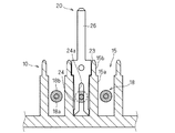
- FIG. 2 is a sectional view taken along line II-II in FIG.
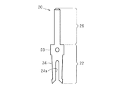
- It is a front view of a press-contact terminal.
- It is a schematic front view of the press-contact terminal insertion apparatus which concerns on 1st Embodiment.
- It is a schematic side view of the press-contact terminal insertion device according to the first embodiment.
- It is a hardware block diagram of the determination part which concerns on 1st Embodiment.
- It is a figure which shows a pressure waveform when a press-contact terminal is inserted favorably.
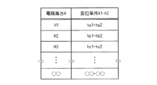
- FIG. It is a figure which shows that the height of the electric wire currently laid by the electric circuit body changes with each insertion hole part. It is a figure which shows the press-contact height when a press-contact terminal is inserted in the insertion hole part from which an electric wire height differs. It is a figure which shows a pressure waveform and a displacement waveform when a press-contact terminal is finally inserted in the insertion hole part by which the electric wire is laid in the height of Ha. It is a figure which shows a pressure waveform and a displacement waveform when a press-contact terminal is finally inserted in the insertion hole part by which the electric wire is laid in the height of Hc. It is a figure which shows the correspondence table of displacement conditions h1-h2 with respect to the electric wire height H. FIG. It is a flowchart which shows the defect determination process of the terminal insertion which concerns on 2nd Embodiment.
- the present press contact terminal inserting device is a device for inserting the press contact terminal into the electric circuit body through the temporary insertion operation and the final insert operation.
- FIG. 1 is a schematic plan view showing the electric circuit body 10 in which the press contact terminal 20 is inserted
- FIG. 2 is a sectional view taken along the line II-II in FIG. 1
- FIG. 3 is a front view of the press contact terminal 20.
- the electric circuit body 10 includes a circuit assembly member 12 formed of an insulating material such as a resin, and electric wires 18 laid on the circuit assembly member 12 with a predetermined wiring pattern.
- the circuit assembly member 12 has a substantially rectangular plate-like member 13 and a plurality of protrusions 14 formed so as to protrude from one main surface of the plate-like member 13.
- An insertion hole 15 into which the press contact terminal 20 can be inserted is formed in the protrusion 14, and a slit portion 16 into which the electric wire 18 can be inserted and extended extends from the distal end portion of the protrusion 14 toward the proximal end portion. Is formed.
- a press-fit portion 15b wider than the back side portion 15a is formed in the opening portion of the insertion hole portion 15, and the press contact terminal 20 is mainly press-fitted into the press-fit portion 15b so that a predetermined position is obtained. And held fixed in posture.
- the electric wire 18 has a configuration in which a covering portion 18b such as an insulating resin is covered around a conductive core wire portion 18a, and is laid in a predetermined wiring pattern passing through the protrusion 14 on one main surface of the plate-like member 13. Has been.
- the electric wire 18 is disposed so as to cross the insertion hole 15 by being inserted and disposed in the slit portion 16 in a portion passing through the protrusion 14.
- the press contact terminal 20 is formed of a conductive plate such as a metal plate, and has an elongated plate shape in which the connection portion 26 and the insertion portion 22 are connected in a straight line.
- the connecting portion 26 is formed in a shape that can be connected to other connector terminals.
- the connection part 26 may be formed in a shape connectable to electrical components such as a fuse and a relay in addition to the connector terminal.
- the insertion portion 22 is a portion that is inserted into the insertion hole portion 15, and includes a press-fit portion 23 that is formed in a portion on the connection portion 26 side and a press-contact portion 24 that is formed in a portion on the tip side thereof. Yes.
- the press-fit portion 23 is formed to be wider (here, slightly wider) than the width of the press-fit portion 15b, and can be press-fitted into the press-fit portion 15b.
- the pressure contact portion 24 has a pressure contact concave portion 24a having a substantially U-shaped slit extending from the distal end side toward the proximal end side.
- the width of the press-contact recess 24a is set to be smaller (slightly smaller here) than the diameter of the core portion 18a of the electric wire 18, and the opening of the press-contact recess 24a is gradually widened in the opening direction. Is formed into a shape.
- the press-contact recess 24a cuts into the covering portion 18b. Finally, both side edges of the press-contact recess 24a come into contact with the core wire portion 18a and electrically. Get connected. Further, the width of the distal end portion of the press contact portion 24 is set to be approximately the same as or smaller (slightly smaller) than the width of the back side portion 15a of the insertion hole portion 15. Then, in a state where the press contact portion 24 is inserted into the back side portion 15a of the insertion hole portion 15, both outer edge portions of the press contact portion 24 come into contact with both side walls of the back side portion 15a, and the opening of the press contact recess 24a is suppressed. The electrical connection state between the pressure contact portion 24 and the core wire portion 18a is more reliably maintained.
- FIG. 4 is a schematic front view of the press contact terminal inserting device 60
- FIG. 5 is a schematic side view of the press contact terminal inserting device 60.
- the X direction in FIGS. 4 and 5 and the Y direction perpendicular thereto are directions that define the operation plane of the XY stage 52 shown in the figure, and the Z direction electrically connects the press contact terminal 20 with the terminal insertion mechanism 30.
- the circuit body 10 is moved closer to and away from the circuit body 10.
- the orientation in the Z direction may be described using the top and bottom according to the attitude of the pressure contact terminal insertion device 60 of FIGS. 4 and 5.
- this direction is used for convenience of explanation, and does not limit the posture or the operation direction of the press contact terminal insertion device 60.
- the press contact terminal insertion device 60 includes a terminal insertion mechanism 30 that inserts the press contact terminal 20 into the electrical circuit body 10 and an electrical circuit body support portion 50 that supports the electrical circuit body 10.
- the electric circuit body support portion 50 is configured to be able to support the electric circuit body 10 in a substantially horizontal posture.
- the electric circuit body support portion 50 is configured by a known support mechanism such as a holding mechanism or a fitting mechanism.
- the electric circuit body support section 50 has a general XY stage 52 composed of a plurality of linear actuators, etc., so that the electric circuit body 10 can be moved on the illustrated XY plane (substantially horizontal plane). keeping.
- the electric circuit body support part 50 arrange
- the electric circuit body 10 is configured to be movable.
- the terminal insertion mechanism section 30 includes a drive mechanism section 32, a lift movement section 34 that is moved up and down by the drive mechanism section 32, and a head section 36 that includes a holding section 38 that holds the press contact terminal 20.
- the drive mechanism unit 32 includes a drive unit and a transmission mechanism (not shown), and is configured to transmit the driving force of the drive unit to the elevation moving unit 34 as a force for moving the elevation moving unit 34 up and down by the transmission mechanism.
- a drive mechanism unit 32 for example, a drive motor as a drive unit and a rotational movement of the drive motor are converted into a linear reciprocating motion in the up-and-down direction of the terminal insertion mechanism unit 30 to be moved up and down.
- the structure provided with the transmission mechanism containing the cam which transmits can be employ
- the up-and-down moving unit 34 and the head unit 36 supported by the up-and-down moving unit 34 are moved up and down.
- the drive mechanism unit 32 is not limited to the configuration of the drive motor and a transmission mechanism such as a cam, but is configured to be able to move the up-and-down moving unit 34 close to and away from the electric circuit body 10 along the Z direction. I just need it.
- the up-and-down moving unit 34 may be configured by an air cylinder, a hydraulic cylinder, a linear motor, or the like.
- the elevating / lowering moving part 34 is supported by the drive mechanism part 32 and the like so as to be movable up and down, and can be moved close to and away from the electric circuit body 10 by driving the drive mechanism part 32.
- the lifting / lowering moving part 34 supports the head part 36 in a suspended manner at the lower end portion on the electric circuit body 10 side, and the head moving part 34 moves up and down to move the head part 36 to the electric circuit body 10.
- the lifting / lowering moving part 34 is stopped and disposed at a top dead center separated from the electric circuit body 10 (here, the position where the holding part 38 is disposed at a position where the press contact terminal 20 is delivered).
- the terminal insertion operation to be described later, it is disposed at a position close to the electric circuit body 10 (position where the press contact terminal 20 held by the holding portion 38 is inserted into the insertion hole portion 15).
- a pressure sensor 40 for detecting the pressure applied to the press contact terminal 20 at the time of inserting the terminal is incorporated in the lifting / lowering moving part 34. This will be described later.
- the head unit 36 is supported by the up-and-down moving unit 34, and is moved close to and away from the electric circuit body 10 held by the XY stage 52 by the movement of the up-and-down moving unit 34 in the Z direction. Further, the head portion 36 has a holding portion 38 capable of holding the press contact terminal 20 on the tip side (lower side) thereof.
- the holding portion 38 has a pair of holding pieces, and one of the pair of holding pieces can be opened and closed with respect to the other, and the one holding piece can be opened and closed with a pressure contact between the pair of holding pieces.
- the terminal 20 can be held and released. More specifically, the holding portion 38 is pressed in such a posture that the insertion portion 22 side of the press contact terminal 20 faces downward (electric circuit body 10 side) and the flat direction of the press contact terminal 20 is substantially parallel to the Y direction.
- the terminal 20 is configured to be held between a pair of holding pieces.
- the holding unit 38 is configured to hold the press contact terminal 20 at the start of temporary insertion and permanent insertion, which will be described later, and to release the holding when temporary insertion and permanent insertion are completed.
- the drive mechanism for opening and closing the one holding piece for example, a configuration is adopted in which the rotational driving force of the motor is transmitted as a force for opening and closing the one holding piece by a transmission mechanism including a cam. can do.
- a drive mechanism may be configured to be incorporated in the holding unit 38 itself, or may be configured to be provided outside the holding unit 38 and to operate the holding piece by pressing one holding piece from the outside. .
- the motor of the drive mechanism unit 32 may be used.
- the drive mechanism that opens and closes one holding piece may have a configuration using an air cylinder, a hydraulic cylinder, an electromagnetic actuator, or the like.
- the holding portion 38 is configured to be able to hold the press-fit portion 23 of the press-contact terminal 20 between a pair of holding pieces at the time of temporary insertion, and at the time of main insertion, the press-fit portion 24 and the press-fit portion 23 of the press-contact terminal 20.
- the connecting portion 26 of the press contact terminal 20 (here, the connecting portion 26 side from the boundary portion between the connecting portion 26 and the press fitting portion 23) can be held.
- the holding portion 38 is disposed at an upper position where it can receive the press contact terminal 20 supplied from a terminal feeding device (not shown), and one holding piece is open. .
- a terminal feeding device not shown
- one holding piece is closed and the press contact terminal 20 is held and received between the pair of holding pieces. Yes.
- the terminal insertion mechanism 30 has a pressure sensor 40 that can detect the pressure applied to the press contact terminal 20 when the press contact terminal 20 is inserted.
- the pressure sensor 40 is composed of a piezo element or the like. When a pressure is applied to the pressure sensor 40, a voltage corresponding to the applied pressure is output as a pressure detection signal due to the piezoelectric effect of the piezoelectric element. And the pressure detection signal of the pressure sensor 40 is output to the determination part 90 mentioned later, and the determination part 90 performs the pass / fail determination of the press contact terminal 20, and the determination of a defective state based on the pressure detection signal.
- the pressure sensor 40 has a through hole in the center, and is provided in a sensor holder 42 interposed between the elevating / lowering moving part 34 and the head part 36. That is, the sensor holder 42 includes an upper sensor holder 42 a fixed to the up-and-down moving unit 34 and a lower sensor holder 42 b fixed to the head unit 36. The pressure sensor 40 is provided between the upper sensor holder 42a and the lower sensor holder 42b along the Z direction.
- the upper sensor holder 42a and the lower sensor holder 42b are connected so as to be relatively close to and away from each other. More specifically, the upper sensor holder 42a has a through hole that opens in a substantially circular shape through which the fixing bolt 44 can be inserted along the Z direction (here, a through hole having a diameter slightly larger than the outer diameter of the fixing bolt 44). ) And a concave portion (in this case, having a diameter slightly larger than the diameter of the head of the fixing bolt 44 and a height of the head). A concave part slightly deeper than that is formed.
- the fixing bolt 44 has an outer diameter that can be inserted into a through hole formed in the pressure sensor 40.
- a concave portion into which a part of the pressure sensor 40 can be fitted in a posture in which the pressure sensor 40 can measure the pressure applied in the Z direction is formed below the upper sensor holder 42a.
- a screw hole into which the fixing bolt 44 can be screwed is formed on the upper side of the lower sensor holder 42b.
- the fixing bolt 44 inserted from the upper side of the upper sensor holder 42a is further inserted through the through hole of the pressure sensor 40 fitted to the lower side of the upper sensor holder 42a. Screwed into the screw hole of the side sensor holder 42b. Thereby, the upper sensor holder 42a and the lower sensor holder 42b are coupled. At this time, there is a gap between the upper sensor holder 42 a and the lower sensor holder 42 b, and it is configured to be indirectly coupled via the pressure sensor 40. Thereby, it can suppress that the pressure at the time of terminal insertion disperse
- a preload can be applied to the pressure sensor 40, and the pressure can be accurately detected from the moment when the pressure is applied when the terminal is inserted.
- the XY stage 52 and the terminal insertion mechanism 30 operate according to a control command from the insertion controller 80.
- the insertion control unit 80 is a general computer having a CPU, a RAM, a ROM, an input / output circuit, etc. (not shown).
- the insertion control unit 80 holds the insertion hole 15 designated as an insertion target in the electrical circuit body 10 into which the press contact terminal 20 is inserted while the electrical circuit body 10 is supported on the XY stage 52.
- a control command for causing the terminal insertion mechanism 30 to perform an insertion operation is given. The terminal insertion operation will be described later.
- the insertion control unit 80 outputs the insertion start signal at the timing when the press contact terminal 20 is held again and the main insertion operation is started as will be described later. Then, the output insertion start signal is input to the determination unit 90 and used for processing for extracting pressure data of the main insertion operation for determining the failure of terminal insertion.
- the insertion control unit 80 only needs to be able to output the insertion start signal at the timing of starting the main insertion operation.
- the insertion control unit 80 measures the time from the start of insertion and outputs the insertion start signal after a predetermined time has elapsed.
- the rotation angle of a motor used as a drive unit in the terminal insertion mechanism 30 may be acquired and an insertion start signal may be output at a predetermined rotation angle.
- the insertion control unit 80 receives the continuation / stop signal output from the determination unit 90, and outputs a control command for stopping the insertion operation to the terminal insertion mechanism unit 30 and the XY stage 52 when the stop signal is received. To stop the insertion operation.
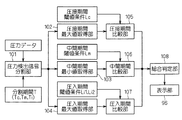
- FIG. 6 is a hardware block diagram of the determination unit 90.
- the determination unit 90 converts time series data of pressure based on the pressure detection signal of the pressure sensor 40 into the pressure contact period Tc and the intermediate period Tm.
- the terminal insertion failure is divided into the press-fitting periods Ti, and it is determined whether or not a preset condition is satisfied in each period, thereby determining the failure of terminal insertion.
- the determination unit 90 has a configuration in which a CPU 92, a RAM 93, a ROM 94, an AD conversion unit 95, a display unit 96, an input unit 97, and an input / output circuit unit 98 are connected by a bus.
- the CPU 92 executes a program stored in the ROM 94 to execute a process of determining whether or not the terminal is inserted and determining a defective state.
- the ROM 94 is a rewritable nonvolatile semiconductor memory such as a flash memory, and stores data such as a divided period T, a threshold condition L, and a program.
- the data of the divided period T and the threshold condition L is appropriately read by the CPU 92 and used for determination.
- the divided period T includes a press-contact period Tc, an intermediate period Tm, and a press-fit period Ti.
- the threshold condition L includes a press-contact period lower limit threshold Lc as a press-contact period threshold condition and an intermediate period as a intermediate period threshold condition.
- the period upper limit threshold Lm, the press-fit period lower limit threshold Li1 and the press-fit period upper limit threshold Li2 as the press-fit period threshold conditions are included. These divided periods T and threshold conditions L will be described later.
- the AD conversion unit 95 is a circuit that converts an analog signal into a digital signal.
- the AD detection unit 95 converts a pressure detection signal (here, a voltage value) output from the pressure sensor 40 into a digital signal at a predetermined sampling period, and generates digital pressure data. And used for the determination process inside the determination unit 90.
- the time-series data of the pressure converted here may be stored in the RAM 93 or may be temporarily stored in the ROM 94 and used for determination processing in the determination unit 90.
- the display unit 96 includes a general liquid crystal display or the like, and is set to display a pressure waveform with time on the horizontal axis and pressure level on the vertical axis based on pressure data (see FIG. 8). That is, when the pressure contact terminal insertion device 60 is inserting a terminal, the pressure detection signal from the pressure sensor 40 is AD converted by the AD conversion unit, and the display unit 96 displays the horizontal axis as time. The pressure waveform with the vertical axis taken as the pressure level is displayed.
- the display unit 96 may be set to display a later-described divided period T and threshold condition L stored in the ROM 94 on the pressure waveform. Moreover, it is good to set so that the quality of a terminal insertion mentioned later and a bad state may be displayed.
- the AD conversion unit 95 and the display unit 96 are incorporated in the determination unit 90, but the AD conversion unit 95 and the display unit 96 are integrally configured as a separate device from the determination unit 90. May be.
- the input unit 97 is configured by a general input device such as a keyboard, a mouse, and a touch panel, and is configured so that an operator can input data such as a divided period T, a threshold condition L, and a program. Data such as the divided period T, the threshold condition L, and the program input by the input unit 97 are stored in the ROM 94, read into the CPU 92 as necessary, and used for various processes.
- the input / output circuit unit 98 is an interface circuit that relays signals between the insertion control unit 80 and the determination unit 90, and is output by the insertion control unit 80 at the timing when the terminal insertion mechanism unit 30 starts the main insertion operation. An insertion start signal is input. Further, at the end of the terminal insertion failure determination, a continuation / stop signal can be output to the insertion control unit 80 according to the result of the insertion failure determination.
- the input / output circuit unit 98 outputs a continuation signal when it is determined that the terminal insertion is good, and outputs a stop signal when it is determined as defective.
- the determination unit 90 includes the pressure detection signal dividing unit 101, the press-contact period maximum value acquisition unit 102, the intermediate period minimum value acquisition unit 103, and the press-fitting period maximum value acquisition unit 104. , A press contact period comparison unit 105, an intermediate period comparison unit 106, a press fit period comparison unit 107, an overall determination unit 108, and a display unit 96.
- the pressure detection signal dividing unit 101 converts the pressure data at the time of the main insertion operation obtained by AD conversion of the pressure detection signal of the pressure sensor 40 into the press contact period Tc, the intermediate period Tm, and the press fit period Ti based on the divided period T. Divide into
- the pressure contact period maximum value acquisition unit 102 acquires the maximum value Pcmax of the pressure data in the pressure contact period Tc among the pressure data divided by the pressure detection signal dividing unit 101. Then, the pressure contact period comparison unit 105 compares the acquired maximum value Pcmax of the pressure contact period Tc with a preset pressure contact period lower limit threshold Lc, and determines that the maximum value Pcmax of the pressure contact period Tc is smaller than the pressure contact period lower limit threshold Lc. If it is determined, it is determined that the pressure contact period threshold condition is not satisfied.
- the intermediate period minimum value acquisition unit 103 acquires the minimum value Pmmin of the pressure data in the intermediate period Tm among the pressure data divided by the pressure detection signal dividing unit 101. Then, the intermediate period comparison unit 106 compares the acquired minimum value Pmmin of the intermediate period Tm with a preset intermediate period upper limit threshold Lm, and determines that the minimum value Pmmin of the intermediate period Tm is greater than the intermediate period upper limit threshold Lm. If it is determined, it is determined that the intermediate period threshold condition is not satisfied.
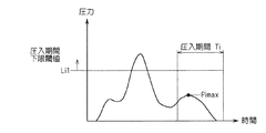
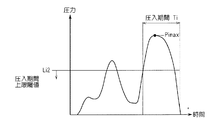
- the press-in period maximum value acquisition unit 104 acquires the maximum value Pimax of the pressure data in the press-in period Ti among the pressure data divided by the pressure detection signal dividing unit 101. Then, the press-in period comparison unit 107 compares the acquired maximum value Pimax of the press-in period Ti with preset press-in period lower limit threshold Li1 and press-in period upper limit threshold Li2, and the maximum value Pimax of the press-in period Ti is lower than the press-in period lower limit. If it is smaller than the threshold Li1, or if it is larger than the press-fit period upper limit threshold Li2, it is determined that the press-fit period threshold condition is not satisfied.
- the overall determination unit 108 determines that terminal insertion is good when the determination results obtained by the press contact period comparison unit 105, the intermediate period comparison unit 106, and the press fit period comparison unit 107 satisfy all the conditions, and the determination result. If one of the results does not satisfy the condition, the terminal insertion is determined to be defective.
- the overall determination unit 108 determines that there is no electric wire or no terminal when the pressure contact period comparison unit 105 determines that the condition is not satisfied (here, the maximum value Pcmax is smaller than the pressure contact period lower limit threshold Lc), If the period comparison unit 106 determines that the condition is not satisfied (here, the minimum value Pmmin is greater than the intermediate period upper limit threshold Lm), it is determined that the terminal position is shifted.
- the overall determination unit 108 determines that the press-fitting is insufficient, and the maximum value Pimax is the press-fitting period upper limit threshold Li2. If it is determined that it is larger, it is determined that there is excessive press-fitting.
- the terminal insertion quality is output to the display unit 96, and the defective state is output to the display unit 96 in the items of no wire or no terminal, terminal displacement, insufficient press-fitting, and insufficient press contact.
- the operator can check the terminal insertion state.
- the display of the terminal insertion state on the display unit 96 can be in various identifiable display forms such as characters or symbols.
- Terminal insertion operation of pressure contact terminal insertion device > Next, the terminal insertion operation of the press contact terminal insertion device 60 will be described.
- the terminal insertion mechanism 30 has a top dead center where the elevating / lowering unit 34 is separated from the electric circuit body 10 (XY stage 52) (here, the holding unit 38 is at a position where the press contact terminal 20 is delivered). It is disposed at a position where it is disposed.
- the holding portion 38 is a transfer position (here, the up-and-down moving portion 34 is moved upward) by the terminal feeding device in a state where one holding piece is open and the pressure contact terminal 20 is not held. (Position at the dead point).
- the XY stage 52 is arranged so that the electric circuit body 10 can be set.
- the operator sets the electric circuit body 10 on the XY stage 52 and inputs a terminal insertion operation start command. Then, a control command for moving the electric circuit body 10 to the XY stage 52 is given by the insertion control unit 80.
- the insertion hole portion 15 designated as the insertion target in the electric circuit body 10 is positioned almost immediately below the position where the holding portion 38 holds the press contact terminal 20 (the proximity movement of the holding portion 38). The electric circuit body 10 is moved so as to be disposed at a position forward in the direction).
- one holding piece of the holding unit 38 is closed by the control command of the insertion control unit 80, and the press contact terminal 20 is held between the pair of holding pieces.
- the holding portion 38 holds the portion from the tip of the connection portion 26 of the press contact terminal 20 to the boundary between the press fit portion 23 and the press contact portion 24.
- the holding portion 38 is lowered by driving the terminal insertion mechanism portion 30 according to a control command of the insertion control portion 80.
- the press contact terminal 20 held by the holding unit 38 starts to move close to the electric circuit body 10 supported by the XY stage 52.
- the press contact terminal 20 is inserted into the insertion hole 15, and the press contact part 24 protruding from the tip of the holding portion 38 of the press contact terminal 20 is inserted into the insertion hole. 15 is inserted halfway.
- the press contact terminal 20 is in a state in which the press contact portion 24 is inserted into the insertion hole 15 to such an extent that it can stand on its own. This insertion operation is called a temporary insertion operation.
- one holding piece of the holding portion 38 is opened and the press contact terminal 20 is released.
- the up-and-down moving part 34 is moved upward by the drive mechanism part 32, and the holding part 38 moves away from the electric circuit body 10. At this time, the tip of the holding portion 38 moves away until it is disposed above the height of the boundary between the connection portion 26 protruding from the insertion hole 15 of the self-standing press contact terminal 20 and the press-fit portion 23.
- the holding portion 38 moves away, the one holding piece is closed again, and the holding portion 38 is substantially the entire connection portion 26 of the press contact terminal 20 (a position slightly above the boundary between the connection portion 26 and the press fitting portion 23). Will be held.
- the up-and-down moving part 34 is again moved downward by the drive mechanism part 32, and the holding part 38 moves close to the electric circuit body 10. Then, first, the press-contact recess 24 a of the press-contact portion 24 of the press-contact terminal 20 is cut into the covering portion 18 b of the electric wire 18 laid on the electric circuit body 10 and is press-connected to the electric wire 18. At this time, the press-contact concave portion 24a comes into contact with the core portion 18a of the electric wire 18 and is electrically connected. Thereafter, the entire press-fit portion 23 is press-fitted into the press-fit portion 15b of the electric circuit body 10, and the press contact terminal 20 is inserted and connected to the insertion hole 15 (see FIG. 2). This insertion operation is called a main insertion operation.
- the holding unit 38 is moved away from the electric circuit body 10 and is supplied with the press contact terminal 20. It is disposed at a receivable position. Further, the XY stage 52 starts moving the electric circuit body 10 to the next designated position. Thereby, the next terminal insertion can be performed.
- FIG. 8 is an example of a pressure waveform when the insertion of the terminal is normally performed
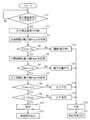
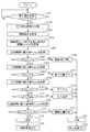
- FIG. 9 is a flowchart of the insertion failure determination of the press contact terminal 20.
- the terminal insertion failure determination is performed by appropriately reading the divided period T and each threshold condition L stored in the ROM 94 by the CPU 92 and dividing the pressure data at the time of the main insertion operation by the divided period T. Thereafter, the terminal insertion failure determination is performed based on the threshold condition L of each period.
- FIG. 8 is an example of a pressure waveform in which pressure is plotted on the vertical axis and time is plotted on the horizontal axis in the pressure data when the insertion operation is normally performed.
- the pressure contact terminal 20 is pressed against the electric wire 18 at the portion where the pressure on the side with the earlier time along the time axis (the left side of the pressure waveform in FIG.
- the portion protruding downward in the meantime is a pressure waveform until the press-fitting operation is started after the press-fitting operation is performed.
- the first small upwardly convex portion is an inertia component when the holding portion 38 starts to move closer from the stop state when the main insertion operation starts.
- a division period T for dividing the pressure waveform (pressure data at the time of the main insertion operation) into periods for each operation is set.
- the divided period T includes a press contact period Tc, an intermediate period Tm, and a press fit period Ti.
- the press-contact period Tc is a period during which the press-contact portion 24 of the press-contact terminal 20 is press-contacted to the electric wire 18 in FIG.
- the press-fitting period Ti is a period during which the press-fit portion 23 of the press contact terminal 20 is press-fitted into the press-fit portion 15 b of the electric circuit body 10.
- the intermediate period Tm is a period between the press-contact period Tc and the press-fit period Ti.
- the divided period T is set experimentally or speculatively by the insertion operation or design value of the press contact terminal 20 by the insertion device, for example, from the time when the insertion start signal is input from the insertion control unit 80. Set as elapsed time.
- the division processing in the pressure detection signal dividing unit 101 is also realized by dividing the elapsed time of the intermediate period T, the press-contact period Tc, and the press-in period Ti with reference to the timing when the insertion start signal is input from the insertion control unit 80. can do.
- the threshold condition L includes a pressing period lower limit threshold Lc, an intermediate period upper limit threshold Lm, a press-fitting period lower limit threshold Li1, and a press-fitting period upper limit threshold Li2, which are threshold conditions for each period.
- the pressure contact period lower limit threshold Lc is a condition for the maximum value Pcmax of the pressure contact period Tc.
- the pressure contact period lower limit threshold Lc defines the lower limit condition of the maximum value Pcmax of the pressure contact period Tc.
- the pressure contact portion 24 is pressure contacted with the electric wire 18, so that the maximum value Pcmax of the main pressure contact period Tc is a value equal to or greater than the predetermined pressure required for pressure contact in the normal terminal insertion state. I guess that. Therefore, when the maximum value Pcmax is smaller than the pressure contact period lower limit threshold Lc, it can be considered that the insertion is defective.
- the reason why the maximum pressure value Pcmax in the pressure contact period Tc is smaller than the pressure contact period lower limit threshold Lc is the case where the pressure contact terminal 20 or the electric wire 18 is not provided.
- the intermediate period upper limit threshold Lm is a condition for the minimum value Pmmin of the intermediate period Tm.
- the intermediate period upper limit threshold Lm defines the upper limit condition of the minimum value Pmmin of the intermediate period Tm. That is, since the intermediate period Tm is a period in which neither pressure contact nor press-fitting is performed, it is estimated that the minimum value Pmmin of the pressure in the intermediate period Tm is not greater than the predetermined pressure in a normal terminal insertion state. Therefore, when the minimum value Pmmin is larger than the intermediate period upper limit threshold Lm, it can be considered that the insertion is defective.
- the reason why the minimum pressure value Pmmin in the intermediate period Tm is larger than the intermediate period upper limit threshold value Lm is that the press contact terminal 20 is not inserted at a normal position (position displacement of the press contact terminal 20). It can be considered that force is generated.
- the press-fit period lower limit threshold Li1 and the press-fit period upper limit threshold Li2 are conditions for the maximum value Pimax of the press-fit period Ti.
- the press-fit period lower limit threshold Li1 is a lower-limit condition
- the press-fit period upper limit threshold Li2 is An upper limit condition is defined.
- the press-fitting period Ti is a period in which the press-contact terminal 20 is press-fitted into the press-fit portion 15b. Therefore, in a normal terminal insertion state, the maximum value Pimax of the main press-fitting period Ti is within a predetermined range necessary for press-fitting. It is assumed that pressure values are observed.
- the threshold condition L set for each period may be a threshold value that defines only a lower limit and an upper limit, or may be a threshold range that defines a range from the lower limit to the upper limit.
- the threshold condition L can be set experimentally or speculatively by inserting the press contact terminal 20.
- step S1 the determination unit 90 determines whether or not an insertion start signal is input. If there is no input, the process of step S1 is repeated. On the other hand, when an insertion start signal is output by the insertion control unit 80 at the timing when this insertion operation is started, this insertion start signal is input to the input / output circuit unit 98. Then, the determination unit 90 determines that an insertion start signal has been input, and proceeds to step S2.
- step S2 the determination unit 90 reads the divided period T stored in the ROM 94 and divides the pressure data into the press contact period Tc, the intermediate period Tm, and the press fit period Ti, and then proceeds to step S3.
- the pressure waveform as shown in FIG. 8 may be displayed on the display unit 96 based on the pressure data of the main insertion period Ta.
- step S3 the pressure contact period maximum value Pcmax is acquired from the pressure data of the divided pressure contact period Tc, and the process proceeds to step S4. That is, the maximum pressure value is searched for in the pressure data of the press contact period Tc, and this value is set as the press contact period maximum value Pcmax.
- step S4 the pressure contact period lower limit threshold value Lc stored in the ROM 94 is read to determine whether or not the pressure contact period maximum value Pcmax is larger than the pressure contact period lower limit threshold value Lc (whether or not the pressure contact period threshold value condition is satisfied).
- the process proceeds to S5, and the pressure contact period maximum value Pcmax is smaller than the pressure contact period lower limit threshold Lc (pressure contact period threshold value). If it is determined that the condition is not satisfied, the process proceeds to step S12.
- the pressure contact period maximum value Pcmax and the pressure contact period lower limit threshold Lc are the same, the process may proceed to either step S5 or step S12.
- step S5 the intermediate period minimum value Tmmin is acquired in the pressure data of the divided intermediate period Tm, and the process proceeds to step S6. That is, the minimum pressure value is searched for in the pressure data of the intermediate period Tm, and this value is set as the intermediate period minimum value Pmmin.
- step S6 the intermediate period upper limit threshold value Lm stored in the ROM 94 is read to determine whether the intermediate period minimum value Pmmin is smaller than the intermediate period upper limit threshold value Lm (whether the intermediate period threshold value condition is satisfied). If it is determined that the intermediate period minimum value Pmmin is smaller than the intermediate period upper limit threshold value Lm (intermediate period threshold value condition is satisfied), the process proceeds to S7, and the intermediate period minimum value Pmmin is larger than the intermediate period upper limit threshold value Lm (intermediate period threshold value). If it is determined that the condition is not satisfied, the process proceeds to step S13.
- the process may proceed to either step S7 or step S13.
- step S7 the press-fit period maximum value Pimax is acquired in the pressure data of the divided press-fit period Ti, and the process proceeds to step S8. That is, the maximum pressure value is searched in the pressure data of the press-fitting period Ti, and this value is set as the press-fit period maximum value Pimax.
- step S8 the press-fit period lower limit threshold Li1 stored in the ROM 94 is read to determine whether the press-fit period maximum value Pimax is larger than the press-fit period lower limit threshold Li1 (whether the lower limit condition of the press-fit period threshold condition is satisfied). To do. When it is determined that the press-fit period maximum value Pimax is larger than the press-fit period lower limit threshold Li1 (the lower limit condition of the press-fit period threshold condition is satisfied), the process proceeds to step S9, and the press-fit period maximum value Pimax is smaller than the press-fit period lower limit threshold Li1 (press fit) If it is determined that the lower limit condition of the period threshold condition is not satisfied, the process proceeds to step S14.
- the press-fit period maximum value Pimax and the press-fit period lower limit threshold Li1 are the same, the process may proceed to either step S9 or step S14.
- step S9 the press-fit period upper limit threshold Li2 stored in the ROM 94 is read to determine whether the press-fit period maximum value Pimax is smaller than the press-fit period upper limit threshold Li2 (whether the upper limit condition of the press-fit period threshold condition is satisfied). To do. If it is determined that the press-fit period maximum value Pimax is smaller than the press-fit period upper limit threshold Li2 (the upper-limit condition of the press-fit period threshold condition is met), the process proceeds to step S10, and the press-fit period maximum value Pimax is greater than the press-fit period upper limit threshold Li2 If it is determined that the upper limit condition of the period threshold condition is not satisfied, the process proceeds to step S15.
- the process may proceed to either step S10 or step S15.
- step S10 it is determined that the terminal insertion state is good and is output to the display unit 96, and the process proceeds to step S11. As a result, good characters are displayed on the display unit 96.
- step S11 a continuation signal for continuing the terminal insertion operation is output. Then, it returns to step S1 and can determine the defect of terminal insertion again.
- step S12 it is determined that terminal insertion is no wire or no terminal, a signal indicating no wire or no terminal is output to the display unit 96, and the process proceeds to step S16.
- no electric wire refers to a state in which the electric wire 18 is not disposed in the slit portion 16 of the protrusion 14 that is the target of the electric circuit body 10.
- no terminal refers to a state in which the terminal insertion operation is performed in a state where the holding portion 38 of the press contact terminal insertion device does not hold the press contact terminal 20 and the press contact terminal 20 is not inserted into the insertion hole 15.
- the pressure is smaller than that during normal terminal insertion (FIG. 8) over the entire period, and the maximum value Pcmax of the press contact period is the lower limit of the press contact period in the press contact period Tc.
- step S13 it is determined that the terminal insertion state is a terminal position shift, a terminal position shift signal is output to the display unit 96, and the process proceeds to step S16.
- the terminal position deviation character is displayed on the display unit 96.
- the displacement of the terminal position means that when the holding portion 38 grips the pressure contact terminal 20, the pressure contact terminal 20 is inserted because it is held obliquely or cannot be held at a predetermined position.
- the posture inserted into the hole portion 15 is different from that during normal insertion, and indicates a state in which alignment failure occurs.
- the pressure in the intermediate period Tm appears larger than that in normal terminal insertion, and a pressure waveform in which the intermediate period minimum value Pmmin is larger than the intermediate period upper limit threshold Lm appears.
- step S14 it is determined that the terminal insertion state is insufficient press-fitting, a signal indicating insufficient press-fitting is output to the display unit 96, and the process proceeds to step S16.
- insufficient press-fitting means that the holding position of the pressure contact terminal 20 by the holding portion 38 is closer to the pressure contact portion 24 than the normal holding position, or the holding portion 38 holding portion of the holding portion 38 slides when the terminal is inserted.
- the press-fit portion 23 of the press contact terminal 20 is press-fitted, the press-fit portion 23 is not completely press-fitted into the press-fit portion 15b.
- the pressure in the press-fitting period Ti appears smaller than that in normal terminal insertion, and a pressure waveform in which the press-fitting period maximum value Pimax is smaller than the press-fitting period lower limit threshold Li1 appears.
- step S15 the terminal insertion state is determined to be excessive press-fitting, an excessive press-fitting signal is output to the display unit 96, and the process proceeds to step S16.
- excessive press-fitting refers to the press-fitting portion when the press-fitting portion 23 of the press-contact terminal 20 is press-fitted because the holding position of the press-contact terminal 20 by the holding portion 38 is closer to the end of the connection portion 26 than the normal grip position.
- the press-fitting portion 23 of the press contact terminal 20 is inserted from the press-fitted portion 15b of the insertion hole 15 to the back side portion 15a side after the press-fitting portion 23 is completely press-fitted into the press-fitted portion 15b.
- the inside of the insertion hole 15 may be damaged.
- the pressure in the press-in period Ti appears larger than that in normal terminal insertion, and a pressure waveform in which the press-in period maximum value Pimax is larger than the press-in period upper limit threshold Li2 appears.
- step S16 it is determined that the terminal insertion state is defective, a failure signal is output to the display unit 96, and the process proceeds to step S17. Thereby, a defective character is displayed on the display unit 96.
- step S17 a stop signal for stopping the terminal insertion operation is output. Then, it returns to step S1 and can determine the defect of terminal insertion again.
- the display of the terminal insertion state on the display unit 96 is not limited to the characters indicating the insertion state as described above, and may be various identifiable display forms such as symbols and figures.
- the operator can remove the press contact terminal 20, determine whether or not the electric circuit body 10 can be used, and remove the press contact terminal by checking the defective state displayed on the display unit 96 as described above. This can be used for investigating the cause of the failure of the insertion device 60 or the like.
- the discrimination processing for each period (S3 and S4, S5 and S6, S7 and S8, and S9) is expressed as serial processing. Any processing configuration of pseudo parallel processing may be used. That is, it is only necessary to perform the determination in each period as described above, and to determine the failure of terminal insertion based on the determination result in each period. In addition, the determination of terminal insertion failure may be changed in order of processing as long as the same determination can be made. However, in the case of a defective state without wires or terminals, it is estimated that the pressure is smaller than the press-fit period lower limit threshold Li1 even during the press-fit period Ti as shown in FIG.
- step S9 when the process of step S9 is performed before the process of step S6, there is a possibility that it is determined as a defective state with insufficient press-fitting, regardless of a defective state without wires or terminals. Therefore, by performing the process of step S6 before the process of step S9, the defective state can be identified more reliably.
- the conditions suitable for determining the terminal insertion state with respect to the pressure at the time of terminal insertion for each of the press-contact period Tc, the intermediate period Tm, and the press-fit period Ti can be determined based on the determination result of each period.
- the terminal insertion failure state can be determined based on the determination result of each period.
- the pressure contact period Tc it is determined whether or not the maximum pressure contact period value Pcmax is larger than the pressure contact period lower limit threshold Lc (whether or not the pressure contact period threshold value is satisfied), and in the intermediate period Tm, the intermediate period minimum value Pmmin is the upper limit of the intermediate period. It is determined whether or not the threshold value Lm is smaller (whether or not the intermediate period threshold value condition is satisfied).
- the press-fitting period Ti whether or not the press-fit period maximum value Pimax is larger than the press-fit period lower limit threshold Li1 and the press-fit period maximum value Pimax are press-fitted. It is determined whether or not it is smaller than the period upper limit threshold Li2 (whether or not the press-fit period threshold condition is satisfied). Thereby, the defective state of terminal insertion can be more appropriately determined based on the determination result of each period.
- the pressure contact period threshold condition is not satisfied
- the intermediate period minimum value Pmmin is the intermediate period upper limit threshold Lm.
- the terminal position is shifted, and it is determined that the press-fit period maximum value Pimax is smaller than the press-fit period lower limit threshold Li1 (does not satisfy the press-fit period threshold condition).
- the electric circuit body 10 is made of plastic or the like. Even when it is formed of a material that is relatively easily deformed and has a large pressure waveform variation when the pressure contact terminal is inserted, erroneous determination due to the influence of the pressure waveform variation can be suppressed.
- the press contact terminal 20 is provided with the holding portion 38 capable of holding and releasing the press contact terminal 20, and the holding portion 38 is held in the state where the press contact terminal 20 is held.
- the pressure sensor 40 that outputs a pressure detection signal corresponding to the pressure applied to the pressure contact terminal 20 when the pressure contact terminal 20 is inserted. Then, based on the pressure detection signal from the pressure sensor 40, the pressure applied to the pressure contact terminal 20 is a pressure contact period Tc in which the pressure contact portion 24 is pressed into the electric wire 18, and a pressure insertion period Ti in which the pressure fit portion 23 is press-fitted into the press-fit portion 15b.
- the pressure data from the start of the main insertion operation is divided into a press-contact period Tc, an intermediate period Tm, and a press-in period Ti provided for each press-in action of the press-in action, press-in action, and the action between the main insertion actions.
- the threshold condition L can be set in each of the intermediate period Tm and the press-fitting period Ti. Thereby, it is determined whether or not the threshold condition L is satisfied in each period, and the insertion failure determination of the press contact terminal 20 can be performed more accurately depending on whether or not all the requirements are satisfied.
- the terminal insertion failure determination method is not limited to the present embodiment.
- the consistency between the pressure reference waveform and the measurement waveform may be observed in each period.
- the terminal insertion failure determination method is shown based on the determination results, the terminal insertion failure state is determined based on the items of no wire or no terminal, terminal displacement, insufficient press-fitting, and excessive press-fitting. Instead, the terminal insertion failure determination method can determine whether or not a condition is satisfied in the press-contact period Tc, the intermediate period Tm, and the press-in period Ti, and can determine a terminal insertion failure state based on the determination result. Anything is acceptable.
- FIG. 14 is a schematic front view of the pressure contact terminal insertion device 160 according to the second embodiment
- FIG. 15 is a diagram showing that the heights of the electric wires 18 laid on the electric circuit body 10 are different
- FIG. It is a figure which shows the press-contact height when a terminal is inserted when length differs.
- differences from the first embodiment will be mainly described, and the same components as those in the first embodiment will be denoted by the same reference numerals and description thereof will be omitted.
- the installation height of the electric wires 18 laid on the electric circuit body 10 may differ depending on the insertion hole 15 (Ha, Hb, Hc). Accordingly, as shown in FIG. 16, the position where the press contact portion 24 of the press contact terminal 20 is press-contacted to the electric wire 18 is also different. That is, if the electric wire 18 is in the upper position (see Ha) near the insertion side opening of the insertion hole 15, the press contact portion 24 is pressed against the electric wire 18 at a relatively early time after the start of insertion. Is at a lower position close to the back side of the insertion hole 15 (see Hc), the pressure contact portion 24 is pressed against the electric wire 18 at a relatively late stage after the start of insertion.
- the terminal insertion device 160 according to the second embodiment has different determination requirements for the electric wires 18 laid at different heights, and aims to more accurately determine terminal insertion failure.
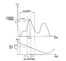
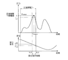
- the terminal insertion device 160 according to the second embodiment uses the displacement sensor 200 to detect the displacement of the holding unit 38 when the terminal is inserted, and the period when the displacement is within a preset displacement condition. (Displacement condition period) It is determined whether or not the maximum value Pcmax of the pressure contact period Tc exists within the condition of Kc1-Kc2.
- the electric circuit body support 50 is provided with the displacement sensor 200.
- the displacement sensor 200 is configured by a non-contact displacement sensor including known sensors such as an eddy current displacement sensor, a laser displacement sensor, an ultrasonic displacement sensor, and the approaching / separating direction of the holding unit 38 with respect to the electric circuit body 10. It is configured to detect a displacement in the (Z direction) and output a displacement detection signal corresponding to the displacement.
- the displacement sensor 200 is disposed at a non-movable portion other than the XY stage 52 of the electric circuit body support section 50. Further, a detected portion support portion 204 is provided above the head portion 36 of the terminal insertion mechanism portion 30.
- the detected portion support portion 204 supports the detected portion 202 so as to be disposed at a position substantially immediately above the displacement sensor 200 disposed in the electric circuit body support portion 50.
- the detected contact terminal insertion device 160 moves closer to and away from the displacement sensor 200.
- the displacement of the holding portion 38 in the approaching / separating direction (Z direction) can be detected.
- the displacement detection signal output from the displacement sensor 200 is input to the determination unit 90, converted into a digital signal at a predetermined sampling period by the AD conversion unit 95 of the determination unit 90, and determined by the determination unit 90 as digital displacement data.
- the time-series data of the AD-converted displacement may be stored in the RAM 93 or may be temporarily stored in the ROM 94 and used for determination processing in the determination unit 90.
- FIG. 17 shows a pressure waveform and a displacement waveform when the press contact terminal 20 is normally inserted into the insertion hole 15 where the electric wire 18 is laid at the height of Ha in FIG. 15, and FIG. These are a pressure waveform and a displacement waveform when the press contact terminal 20 is normally fully inserted into the insertion hole 15 where the electric wire 18 is laid at a height.
- the press contact portion 24 When the electric wire 18 is laid at a height of Ha (a position higher than Hc), the press contact portion 24 is pressed against the electric wire 18 at a relatively early time after the start of insertion, as shown in FIG.
- the time when the maximum value Pcmax of the pressure contact period Tc appears (the pressure contact period maximum value time Tcmax) also appears at a relatively early point.
- the press contact portion 24 when the electric wire 18 is laid at the height of Hc (position lower than Ha), as shown in FIG. 18, the press contact portion 24 is pressed against the electric wire 18 at a relatively late stage after the start of insertion. Therefore, the pressure contact period maximum value time Tcmax also appears at a relatively late time point.
- the maximum pressure contact period time Tcmax appears within a period in which the holding portion 38 of the press contact terminal insertion device 60 is located in a certain displacement range based on the electric wire position. Guessed. Therefore, when the pressure contact period maximum value time Tcmax does not appear within a period based on a preset displacement range, it can be considered that the electric wire position is abnormal.
- the heights of the electric wires 18 laid at different heights in the electric circuit body 10 are divided into several levels to be the electric wire heights H, and are pressed against the electric wire heights H in the respective insertion holes 15.
- a displacement condition h1-h2 where the maximum value Pcmax of the period Tc should appear is set in advance.
- the display unit 96 can display a correspondence table of the displacement conditions h1-h2 with respect to the wire height H as shown in FIG. 19, and the input unit 97 displays the wire height H and the displacement conditions h1-h2 in the correspondence table. Input is enabled.
- the wire height H input by the input unit 97 and the corresponding displacement conditions h1-h2 are stored in the ROM 94 and read into the CPU 92 as appropriate.
- the information of the height of the electric wire 18 laid in the electric circuit body 10 is stored in the ROM 94 for each insertion hole 15 in the order of insertion as the electric wire height H divided into several levels.
- the data is read by the CPU 92 as appropriate.
- the data of the wire height H for each insertion hole 15 may be input from the input unit 97. Since the electric wire height H is determined according to the wiring pattern of the electric wires 18 laid on the electric circuit body 10 or the shape of the slit portion 16, the electric wire height H is determined based on the specifications of the electric circuit body 10 itself. Good.
- the correspondence between the level of the wire height H and the displacement condition h1-h2 depends on the length of the pressure contact portion 24 of the pressure contact terminal 20, the depth of the pressure contact recess 24a, the height of the wire, and the like. Can be set speculatively.
- FIG. 20 is a flowchart showing terminal insertion failure determination processing of the press-contact terminal insertion device 160 according to the second embodiment.
- step S101 the determination unit 90 determines whether or not an insertion start signal has been input. If there is no input, the process of step S101 is repeated. On the other hand, when an insertion start signal is output by the insertion control unit 80 at the timing when this insertion operation is started, this insertion start signal is input to the input / output circuit unit 98. Then, the determination unit 90 determines that an insertion start signal has been input, and proceeds to step S102.
- step S102 the determination unit 90 reads the divided period T stored in the ROM 94 and divides the pressure data into the press-contact period Tc, the intermediate period Tm, and the press-fit period Ti, and then proceeds to step S103.
- the pressure waveform as shown in FIGS. 17 and 18 may be displayed on the display unit 96 based on the pressure data of the main insertion period Ta.
- step S103 the wire height H at the designated insertion hole 15 is read from the wire height H data stored in the ROM 94, and the process proceeds to step S104.
- step S104 the displacement condition h1-h2 corresponding to the wire height H in the designated insertion hole 15 read in step S103 is selected from the correspondence relationship between the wire height H stored in the ROM 94 and the displacement condition h1-h2. Read and go to step S105. Then, based on the displacement waveform (displacement data) output from the displacement sensor 200, a period in which the displacement is within the displacement condition h1-h2 is searched in the pressure contact period Tc, and this period is set as the displacement condition period Kc1-Kc2. . At this time, the displacement condition h1-h2 may be a condition including or not including h1 and h2.
- step S105 the pressure contact period maximum value Pcmax is acquired from the pressure data of the divided pressure contact period Tc, and the process proceeds to step S106. That is, the maximum pressure value is searched for in the pressure data of the press contact period Tc, and this value is set as the press contact period maximum value Pcmax.
- the pressure contact period lower limit threshold value Lc stored in the ROM 94 is read, and it is determined whether or not the pressure contact period maximum value Pcmax is larger than the pressure contact period lower limit threshold value Lc (whether or not the pressure contact period threshold value condition is satisfied).
- the process proceeds to S107, and the pressure contact period maximum value Pcmax is smaller than the pressure contact period lower limit threshold Lc (pressure contact period threshold value). If it is determined that the condition is not satisfied, the process proceeds to step S116.
- the pressure contact period maximum value Pcmax and the pressure contact period lower limit threshold Lc are the same, the process may proceed to either step S107 or step S116.
- step S107 the intermediate period minimum value Pmmin is acquired in the pressure data of the divided intermediate period Tm, and the process proceeds to step S108. That is, the minimum pressure value is searched for in the pressure data of the intermediate period Tm, and this value is set as the intermediate period minimum value Pmmin.
- step S108 the intermediate period upper limit threshold value Lm stored in the ROM 94 is read to determine whether the intermediate period minimum value Pmmin is smaller than the intermediate period upper limit threshold value Lm (whether the intermediate period threshold value condition is satisfied).
- the process proceeds to S109, and the intermediate period minimum value Pmmin is larger than the intermediate period upper limit threshold Lm (intermediate period threshold value). If it is determined that the condition is not satisfied, the process proceeds to step S117.
- the process may proceed to either step S109 or step S117.
- step S109 the press-fit period maximum value Pimax is acquired in the pressure data of the divided press-fit period Ti, and the process proceeds to step S110. That is, the maximum pressure value is searched in the pressure data of the press-fitting period Ti, and this value is set as the press-fit period maximum value Pimax.
- step S110 the press-fit period lower limit threshold Li1 stored in the ROM 94 is read to determine whether the press-fit period maximum value Pimax is larger than the press-fit period lower limit threshold Li1 (whether the lower limit of the press-fit period threshold condition is satisfied). To do. When it is determined that the press-fit period maximum value Pimax is larger than the press-fit period lower limit threshold Li1 (satisfying the lower limit of the press-fit period threshold condition), the process proceeds to step S111, and the press-fit period maximum value Pimax is smaller than the press-fit period lower limit threshold Li1 ( If it is determined that the lower limit of the press-fitting period threshold value condition is not satisfied, the process proceeds to step S118. Here, if the press-fit period maximum value Pimax and the press-fit period lower limit threshold Li1 are the same, the process may proceed to either step S111 or step S118.
- step S111 the press-fit period upper limit threshold Li2 stored in the ROM 94 is read to determine whether the press-fit period maximum value Pimax is smaller than the press-fit period upper limit threshold Li2 (whether the upper limit of the press-fit period threshold condition is satisfied). .
- the process proceeds to step S112, and the press-fit period maximum value Pimax is greater than the press-fit period upper limit threshold Li2 (press-fit period). If it is determined that the upper limit of the threshold condition is not satisfied, the process proceeds to step S119.
- the press-fit period maximum value Pimax and the press-fit period upper limit threshold Li2 are the same, the process may proceed to either step S112 or step S119.
- step S112 the pressure contact period maximum value time Tcmax in which the pressure contact period maximum value Pcmax appears in the pressure contact period Tc is acquired, and the process proceeds to step S113. That is, in the pressure data of the pressure contact period Tc, the time when the pressure contact period maximum value Pcmax appears is searched, and this value is set as the pressure contact period maximum value time Tcmax.
- step S113 whether or not the pressure contact period maximum value time Tcmax acquired in step S112 satisfies the displacement condition period Kc1-Kc2 acquired in step S104, that is, the pressure contact period maximum value time Tcmax is larger than the time Kc1 and the time Kc2. Or less. If the determination result is YES, the process proceeds to step S114. If the determination result is NO, the process proceeds to step S120. Here, when the pressure contact period maximum value time Tcmax and the displacement condition period Kc1 or Kc2 are the same, the process may proceed to either step S114 or step S120.
- step S114 the terminal insertion state is determined to be good, a signal indicating that the terminal is inserted is output to the display unit 96, and the process proceeds to step S115. As a result, good characters are displayed on the display unit 96. In step S115, a continuation signal for continuing the terminal insertion operation is output. Thereafter, the process returns to step S101, and the terminal insertion failure determination can be performed again.
- step S116 the terminal insertion state is determined as no wire or no terminal, a signal indicating no wire or no terminal is output to the display unit 96, and the process proceeds to step S121. As a result, characters without wires or terminals are displayed on the display unit 96.
- step S117 the terminal insertion state is determined to be a terminal position shift, a terminal position shift signal is output to the display unit 96, and the process proceeds to step S121. As a result, the terminal position deviation character is displayed on the display unit 96.
- step S118 the terminal insertion state is determined to be insufficient press-fitting, a signal indicating insufficient press-fitting is output to the display unit 96, and the process proceeds to step S121. As a result, characters with insufficient press-fitting are displayed on the display unit 96.
- step S119 the terminal insertion state is determined to be excessive press-fitting, an excessive press-fitting signal is output to the display unit 96, and the process proceeds to step S121. As a result, excessive press-fitting characters are displayed on the display unit 96.
- step S120 the terminal insertion state is determined to be an electric wire position abnormality, and an electric wire position abnormality signal is output to the display unit 96, and the process proceeds to step S121.
- the electric wire position abnormality character is displayed on the display unit 96.
- the electric wire position abnormality refers to a state in which the electric wire 18 disposed in the slit portion 16 of the protrusion 14 to be the target of the electric circuit body 10 is not at a specified height.
- the pressure contact period maximum value time Tcmax in which the pressure contact period maximum value Pcmax occurs in the pressure contact period Tc is outside the displacement condition period Kc1-Kc2 (time earlier or later than the displacement condition period Kc1-Kc2). A pressure waveform appears.
- step S121 the terminal insertion state is determined to be defective, a failure signal is output to the display unit 96, and the process proceeds to step S122. Thereby, a defective character is displayed on the display unit 96.
- step S122 a stop signal for stopping the terminal insertion operation is output. Thereafter, the process returns to step S101, and the terminal insertion failure determination can be performed again.
- the display of the terminal insertion state on the display unit 96 is not limited to the characters indicating the insertion state as described above, and may be various identifiable display forms such as symbols and figures.
- the operator can remove the press contact terminal 20, determine whether or not the electric circuit body 10 can be used, and remove the press contact terminal by checking the defective state displayed on the display unit 96 as described above. This can be useful for investigating the cause of the failure of the insertion device 160 or the like.
- the determination processing for each period (steps S105 and S106, S107 and S108, S109 and S110, S111, S112, and S113) is expressed in a serial process.
- Any processing configuration of processing, serial processing, or pseudo-parallel processing may be used, as long as it is possible to determine the terminal insertion failure by performing the determination in each period as described above and combining the determination results of all the periods. .
- the determination of terminal insertion failure may be changed in order of processing as long as the same determination can be made.
- the timing (maximum pressure period time Tcmax) at which the pressure contact period maximum value Pcmax occurs as shown in FIG. 11 may be delayed from the normal terminal insertion time (FIG.
- step S108 can be more reliably identified by performing the process in step S113 before the process in step S113.
- the displacement condition h1-h2 is set for the specified wire height H, and the displacement condition period Kc1-Kc2 in which the displacement data of the holding portion 38 at the time of terminal insertion is within the displacement condition h1-h2 is acquired. . Then, the terminal insertion failure determination is performed by determining whether or not the pressure contact period maximum value time Tcmax in which the pressure contact period maximum value Pcmax appears satisfies the displacement condition period Kc1-Kc2.
- the press contact terminal insertion device 160 configured as described above is configured to be able to acquire displacement data based on the displacement detection signal of the displacement sensor 200 disposed on the electric circuit body support 50.
- the determination unit 90 of the press contact terminal insertion device 160 stores the wire height H in each insertion hole 15 and acquires the information on the height of the insertion hole 15 into which the terminal is inserted.
- a displacement condition h1-h2 in which the pressure contact period maximum value Pcmax appears when favorable terminal insertion is performed is set in advance, and the displacement condition period Kc1-Kc2 is within the displacement condition h1-h2. Is acquired.
- the terminal insertion failure determination method is applied to the pressure contact terminal insertion devices 60 and 160 .
- this terminal insertion failure determination method is also applied to terminal insertion devices other than the pressure contact terminal insertion devices 60 and 160.
- the present invention can also be applied to a case where the press contact terminal is inserted by a single insertion operation without going through a temporary insertion operation.
Landscapes
- Manufacturing Of Electrical Connectors (AREA)
- Testing Of Short-Circuits, Discontinuities, Leakage, Or Incorrect Line Connections (AREA)
Abstract
Description
以下、第1実施形態に係る端子挿入不良判定方法について説明する。ここでは、圧接端子挿入装置60に適用した例で説明する。本圧接端子挿入装置は、仮挿入動作と本挿入動作との動作を経て圧接端子を電気回路体に挿入するための装置である。
説明の便宜上、まず対象となる電気回路体10及び圧接端子20について説明する。図1は圧接端子20が挿入された電気回路体10を示す概略平面図、図2は図1におけるII-II線断面図、図3は圧接端子20の正面図である。
<2.1.圧接端子挿入装置の全体構成>
次に、圧接端子挿入装置60について説明する。図4は圧接端子挿入装置60の概略正面図、図5は圧接端子挿入装置60の概略側面図である。
次に、本圧接端子挿入装置60の端子挿入動作について説明する。
次に、判定部90及びその端子挿入不良判定についてより詳細に説明する。図8は端子の挿入が正常に行われたときの圧力波形例、図9は圧接端子20の挿入不良判定のフローチャートである。
次に、第2実施形態に係る圧接端子挿入装置について説明する。図14は第2実施形態に係る圧接端子挿入装置160の概略正面図、図15は電気回路体10に敷設されている電線18の高さが異なることを示す図、図16は電線18の高さが異なる場合に端子を挿入したときの圧接高さを示す図である。なお、本実施の形態の説明において、第1実施形態との相違点を中心に説明し、第1実施形態と同様の構成部分については同一符号を付してその説明を省略する。
Claims (7)
- 被圧入部が形成された挿入穴部を有し前記挿入穴部を横切るようにして電線が敷設された電気回路体の前記挿入穴部に、前記電線に圧接可能な圧接部と前記圧接部が前記電線に圧接された後に前記被圧入部に圧入される圧入部とを有する圧接端子を挿入する際、前記圧接端子の挿入不良を判定する端子挿入不良判定方法であって、
(a)前記圧接部が前記電線に圧接される圧接期間における圧力が、予め設定された条件を満たすか否かを判別し、条件を満たさないと判別された場合にその不良状態を判定する工程と、
(b)前記圧接期間と前記圧入部が前記被圧入部に圧入される圧入期間との中間期間における圧力が、予め設定された条件を満たすか否かを判別し、条件を満たさないと判別された場合にその不良状態を判定する工程と、
(c)前記圧入期間における圧力が、予め設定された条件を満たすか否かを判別し、条件を満たさないと判別された場合にその不良状態を判定する工程と、
を備える端子挿入不良判定方法。 - 請求項1に記載の端子挿入不良判定方法であって、
前記工程(a)では、前記圧接期間における圧力の最大値が予め設定された圧接期間閾値条件を満たすか否かを判別して、前記圧接期間閾値条件を満たさないと判別された場合にその不良状態を判定し、
前記工程(b)では、前記中間期間における圧力の最小値が予め設定された中間期間閾値条件を満たすか否かを判別し、前記中間期間閾値条件を満たさないと判別された場合にその不良状態を判定し、
前記工程(c)では、前記圧入期間における圧力の最大値が予め設定された圧入期間閾値条件を満たすか否かを判別して、前記圧入期間閾値条件を満たさないと判別された場合にその不良状態を判定する、端子挿入不良判定方法。 - 請求項2に記載の端子挿入不良判定方法であって、
前記工程(a)における前記圧接期間閾値条件として、前記圧接期間における圧力の最大値が満たすべき圧接期間下限閾値が設定され、
前記工程(b)における前記中間期間閾値条件として、前記中間期間における圧力の最小値が満たすべき中間期間上限閾値が設定され、
前記工程(c)における圧入期間閾値条件として、前記圧入期間における圧力の最大値が満たすべき圧入期間下限閾値が設定される、端子挿入不良判定方法。 - 請求項3記載の端子挿入不良判定方法であって、
前記工程(a)では、前記圧接期間における圧力の最大値が、前記圧接期間下限閾値を満たさないと判別された場合に電線なし又は端子なしと判定し、
前記工程(b)では、前記中間期間における圧力の最小値が、前記中間期間上限閾値を満たさないと判別された場合に端子位置ずれと判定し、
前記工程(c)では、前記圧入期間における圧力の最大値が、前記圧入期間下限閾値を満たさないと判別された場合に圧入不足と判定する、端子挿入不良判定方法。 - 請求項3記載の端子挿入不良判定方法であって、
前記工程(c)における圧入期間閾値条件として、前記圧入期間における圧力の最大値が満たすべき圧入期間上限閾値がさらに設定される、端子挿入不良判定方法。 - 請求項5記載の端子挿入不良判定方法であって、
前記工程(a)では、前記圧接期間における圧力の最大値が、前記圧接期間下限閾値を満たさないと判別された場合に電線なし又は端子なしと判定し、
前記工程(b)では、前記中間期間における圧力の最小値が、前記中間期間上限閾値を満たさないと判別された場合に端子位置ずれと判定し、
前記工程(c)では、前記圧入期間における圧力の最大値が、前記圧入期間下限閾値を満たさないと判別された場合に圧入不足と判定し、前記圧入期間上限閾値を満たさないと判別された場合に圧入過多と判定する、端子挿入不良判定方法。 - 請求項1~請求項6のいずれかに記載の端子挿入不良判定方法であって、
(d)前記圧接期間内において前記圧接端子にかかる圧力の最大値を生ずるタイミングを求め、前記タイミングが前記圧接端子の変位に応じて決定される期間内にあるか否かを判別し、当該期間内に無い場合に電線位置異常と判定する工程、をさらに含む端子挿入不良判定方法。
Priority Applications (2)
| Application Number | Priority Date | Filing Date | Title |
|---|---|---|---|
| US12/996,019 US20110184682A1 (en) | 2008-10-15 | 2009-02-17 | Terminal insertion defect determining method |
| CN2009801050999A CN101946375B (zh) | 2008-10-15 | 2009-02-17 | 端子插入缺陷判定方法 |
Applications Claiming Priority (2)
| Application Number | Priority Date | Filing Date | Title |
|---|---|---|---|
| JP2008-266283 | 2008-10-15 | ||
| JP2008266283A JP5051094B2 (ja) | 2008-10-15 | 2008-10-15 | 端子挿入不良判定方法 |
Publications (1)
| Publication Number | Publication Date |
|---|---|
| WO2010044284A1 true WO2010044284A1 (ja) | 2010-04-22 |
Family
ID=42106454
Family Applications (1)
| Application Number | Title | Priority Date | Filing Date |
|---|---|---|---|
| PCT/JP2009/052606 Ceased WO2010044284A1 (ja) | 2008-10-15 | 2009-02-17 | 端子挿入不良判定方法 |
Country Status (4)
| Country | Link |
|---|---|
| US (1) | US20110184682A1 (ja) |
| JP (1) | JP5051094B2 (ja) |
| CN (1) | CN101946375B (ja) |
| WO (1) | WO2010044284A1 (ja) |
Cited By (1)
| Publication number | Priority date | Publication date | Assignee | Title |
|---|---|---|---|---|
| JP2018125978A (ja) * | 2017-02-01 | 2018-08-09 | トヨタ自動車株式会社 | ジャンクションボックスの良否判定方法 |
Families Citing this family (6)
| Publication number | Priority date | Publication date | Assignee | Title |
|---|---|---|---|---|
| JP5215331B2 (ja) * | 2010-02-03 | 2013-06-19 | トヨタ自動車東日本株式会社 | 作業判定システム及び作業判定方法並びに該作業判定方法を記録した記録媒体 |
| JP5858806B2 (ja) * | 2012-01-27 | 2016-02-10 | 新日鐵住金株式会社 | ブレーキディスク付き鉄道車輪の組立て装置 |
| JP5753500B2 (ja) * | 2012-01-27 | 2015-07-22 | 新日鐵住金株式会社 | ブレーキディスク付き鉄道車輪におけるブレーキディスクのうねり測定装置 |
| JP6629263B2 (ja) * | 2017-06-06 | 2020-01-15 | 矢崎総業株式会社 | 端子ズレ量検知方法、端子挿入方法、端子ズレ量検知装置、及び端子挿入装置 |
| JP6590863B2 (ja) * | 2017-06-06 | 2019-10-16 | 矢崎総業株式会社 | 端子挿入方法及び端子挿入装置 |
| CN118583038B (zh) * | 2024-08-02 | 2024-10-18 | 浙江明禾新能科技股份有限公司 | 端子检测工装 |
Citations (2)
| Publication number | Priority date | Publication date | Assignee | Title |
|---|---|---|---|---|
| JP2003123932A (ja) * | 2001-10-19 | 2003-04-25 | Furukawa Electric Co Ltd:The | 圧接端子と被覆電線の接続状態検知方法 |
| JP2004080886A (ja) * | 2002-08-14 | 2004-03-11 | Furukawa Electric Co Ltd:The | 電気接続箱および電気接続箱のタブアライメント保持具 |
Family Cites Families (4)
| Publication number | Priority date | Publication date | Assignee | Title |
|---|---|---|---|---|
| JP3282977B2 (ja) * | 1996-11-22 | 2002-05-20 | 株式会社オートネットワーク技術研究所 | 圧接端子の設計方法 |
| JP4176977B2 (ja) * | 2000-09-28 | 2008-11-05 | 矢崎総業株式会社 | 端子金具の検査装置 |
| CN1297044C (zh) * | 2001-06-15 | 2007-01-24 | 矢崎总业株式会社 | 接线端压接状态的测试方法 |
| JP4069321B2 (ja) * | 2003-07-25 | 2008-04-02 | 住友電装株式会社 | 端子の挿入量検査装置 |
-
2008
- 2008-10-15 JP JP2008266283A patent/JP5051094B2/ja not_active Expired - Fee Related
-
2009
- 2009-02-17 CN CN2009801050999A patent/CN101946375B/zh not_active Expired - Fee Related
- 2009-02-17 WO PCT/JP2009/052606 patent/WO2010044284A1/ja not_active Ceased
- 2009-02-17 US US12/996,019 patent/US20110184682A1/en not_active Abandoned
Patent Citations (2)
| Publication number | Priority date | Publication date | Assignee | Title |
|---|---|---|---|---|
| JP2003123932A (ja) * | 2001-10-19 | 2003-04-25 | Furukawa Electric Co Ltd:The | 圧接端子と被覆電線の接続状態検知方法 |
| JP2004080886A (ja) * | 2002-08-14 | 2004-03-11 | Furukawa Electric Co Ltd:The | 電気接続箱および電気接続箱のタブアライメント保持具 |
Cited By (1)
| Publication number | Priority date | Publication date | Assignee | Title |
|---|---|---|---|---|
| JP2018125978A (ja) * | 2017-02-01 | 2018-08-09 | トヨタ自動車株式会社 | ジャンクションボックスの良否判定方法 |
Also Published As
| Publication number | Publication date |
|---|---|
| JP2010097758A (ja) | 2010-04-30 |
| CN101946375A (zh) | 2011-01-12 |
| US20110184682A1 (en) | 2011-07-28 |
| JP5051094B2 (ja) | 2012-10-17 |
| CN101946375B (zh) | 2012-10-17 |
Similar Documents
| Publication | Publication Date | Title |
|---|---|---|
| JP5051094B2 (ja) | 端子挿入不良判定方法 | |
| JP6396008B2 (ja) | ケーブルの絶縁体剥離方法 | |
| JP6052787B2 (ja) | 打ち抜き加工による切断面の良否判定方法 | |
| JP2012233778A (ja) | 接触端子装置 | |
| US20070062237A1 (en) | Crimping Device | |
| EP2023450B1 (en) | Method of connecting flat cable to connecting terminal | |
| JP2009272116A (ja) | 端子検査治具及び端子検査方法 | |
| JP6000046B2 (ja) | プローブユニットおよび検査装置 | |
| US6308430B1 (en) | Examination of insulation displacement connection | |
| JP2006234428A (ja) | コンタクトプローブおよび検査装置 | |
| JP2008108971A (ja) | ワイヤボンディング装置及びワイヤボンディング方法 | |
| JP2008261678A (ja) | 検査プローブ接触検知機構および回路基板検査装置 | |
| KR20090111097A (ko) | 피씨비 기판의 핀 불량 삽입 검출방법 및 그 검출 지그장치 | |
| JP2010040481A (ja) | 端子圧着状態良否判別装置、端子圧着加工装置、端子圧着状態良否判別方法及び端子圧着状態良否判別プログラム | |
| JP2021077794A (ja) | ピンの圧入管理装置、管理方法、管理プログラム、及びピン付属基板の製造方法 | |
| JP3708287B2 (ja) | 自動車用ワイヤーハーネス製造における電線の圧接 | |
| JP2691201B2 (ja) | 圧着機及び圧着方法 | |
| CN2465191Y (zh) | 横杆式探针测试装置 | |
| JP4030275B2 (ja) | フラットケーブルと接続端子との接続時の接続不良検出方法 | |
| JP5431524B2 (ja) | 検査プローブ接触検知機構および回路基板検査装置 | |
| KR20110044352A (ko) | 전극을 이용한 금속 인서트 감지장치 | |
| JP4282083B2 (ja) | マイクロクラック検査方法及び装置 | |
| KR20190071880A (ko) | 피부 감각 측정 장치 및 피부 감각 측정 방법 그리고 피부 탄성도 측정 장치 및 피부 탄성도 측정 방법 | |
| JP4308038B2 (ja) | 部品実装検査方法および回路基板検査装置 | |
| KR20250099386A (ko) | 플렉스 케이블의 접합 과정의 모니터링을 위한 방법 및 플렉스 케이블 |
Legal Events
| Date | Code | Title | Description |
|---|---|---|---|
| WWE | Wipo information: entry into national phase |
Ref document number: 200980105099.9 Country of ref document: CN |
|
| 121 | Ep: the epo has been informed by wipo that ep was designated in this application |
Ref document number: 09820462 Country of ref document: EP Kind code of ref document: A1 |
|
| WWE | Wipo information: entry into national phase |
Ref document number: 12996019 Country of ref document: US |
|
| NENP | Non-entry into the national phase |
Ref country code: DE |
|
| 122 | Ep: pct application non-entry in european phase |
Ref document number: 09820462 Country of ref document: EP Kind code of ref document: A1 |