WO2010041508A1 - フォトマスク - Google Patents
フォトマスク Download PDFInfo
- Publication number
- WO2010041508A1 WO2010041508A1 PCT/JP2009/063672 JP2009063672W WO2010041508A1 WO 2010041508 A1 WO2010041508 A1 WO 2010041508A1 JP 2009063672 W JP2009063672 W JP 2009063672W WO 2010041508 A1 WO2010041508 A1 WO 2010041508A1
- Authority
- WO
- WIPO (PCT)
- Prior art keywords
- photomask
- base material
- frame
- ene
- humidity
- Prior art date
- Legal status (The legal status is an assumption and is not a legal conclusion. Google has not performed a legal analysis and makes no representation as to the accuracy of the status listed.)
- Ceased
Links
Images


Classifications
-
- G—PHYSICS
- G03—PHOTOGRAPHY; CINEMATOGRAPHY; ANALOGOUS TECHNIQUES USING WAVES OTHER THAN OPTICAL WAVES; ELECTROGRAPHY; HOLOGRAPHY
- G03F—PHOTOMECHANICAL PRODUCTION OF TEXTURED OR PATTERNED SURFACES, e.g. FOR PRINTING, FOR PROCESSING OF SEMICONDUCTOR DEVICES; MATERIALS THEREFOR; ORIGINALS THEREFOR; APPARATUS SPECIALLY ADAPTED THEREFOR
- G03F1/00—Originals for photomechanical production of textured or patterned surfaces, e.g., masks, photo-masks, reticles; Mask blanks or pellicles therefor; Containers specially adapted therefor; Preparation thereof
- G03F1/60—Substrates
Definitions
- the present invention relates to a photomask used for manufacturing an electric circuit board such as a semiconductor, a liquid crystal display or a printed wiring board, and etching a metal foil.
- the mask used for this photolithography is usually called a photomask or a reticle, and generally comprises an optically transparent base material and a light shielding layer provided on the surface of the base material.
- photomasks masks used for photolithography called photomasks or reticles are collectively referred to as “photomasks”.
- a polyester film and a glass such as soda lime glass or quartz glass are appropriately selected and used according to required characteristics.
- a polyester film is often used when the line width of the pattern is relatively large and the required accuracy regarding the position and shape is not strict, such as etching processing of a printed wiring board or metal foil.
- glass such as soda lime glass or quartz glass was exclusively used when the line width of the pattern was small and the required accuracy regarding the position and shape was severe as in semiconductors and liquid crystal displays.
- the change in humidity caused by the weather is particularly large compared to the change in temperature, and it greatly affects the accuracy and shape of photomasks using polyester film as a base material. In dealing with this, the biggest problem was suppression of dimensional changes accompanying changes in humidity.
- Patent Documents 1 and 2 disclose techniques for stacking to reduce dimensional changes.
- Patent Document 1 and Patent Document 2 still has a dimensional change accompanying changes in temperature and humidity, compared to a substrate using glass. However, it was still large and could not always cope with the recent demands for finer patterns and stricter required accuracy.
- the present invention can cope with the recent thinning of the pattern of printed wiring boards and the strictness of required accuracy without using glass as a base material, and uses a polyester film as a base material.
- An object is to provide a photomask having the same convenience as the case.
- the photomask of the present invention is A substrate made of a film or sheet mainly composed of a polymer compound; A light shielding layer disposed on at least one surface of the substrate; A frame disposed on at least one surface of the substrate; A photomask comprised of at least The photomask is In an atmosphere where it is used and stored, The base material is fixed to the frame in a tensioned state.
- the photomask of the present invention can be used or stored in the same manner as a photomask using a substrate made of glass in response to the recent demands for thinning the pattern and stricter accuracy requirements. This can be dealt with without special adjustment, and the manufacturing cost can be reduced.
- the photomask of the present invention is
- the frame is made of a material having a coefficient of thermal expansion of 35 ppm / ° C. or less.
- a photomask using a frame made of a material having such a coefficient of thermal expansion has no dimensional change associated with a change in humidity, and the dimensional change associated with a temperature change is smaller than that of a conventional photomask. Therefore, it is possible to cope with the situation without special adjustment of the atmosphere, and the manufacturing cost can be reduced.
- the photomask of the present invention is The substrate is characterized in that the coefficient of thermal expansion is higher than the coefficient of linear expansion of humidity.
- the frame is necessary to always maintain tension against the dimensional change accompanying the humidity change in the atmosphere used and stored.
- the fixed temperature can be set widely, and the choice of processing conditions is expanded.
- the photomask of the present invention is
- the base material has a cyclic olefin resin as a main component.
- Such a base material mainly composed of a cyclic olefin resin is suitable because it has high heat resistance and has a wide selection range of fixing temperature, low water absorption and low coefficient of linear expansion of humidity.
- the present invention even if glass is not used as a base material, it can cope with the recent thinning of printed wiring board patterns and stricter required accuracy, and is equivalent to the case where a polyester film is used as a base material.
- a photomask having convenience can be provided.
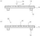
- FIG. 1 is a schematic view of a photomask of the present invention
- FIG. 1 (a) is a front view
- FIG. 1 (b) is a cross-sectional view taken along line XX of FIG. 1 (a).
- FIG. 2 is an explanatory diagram for explaining a pattern formed on the photomask of the present invention.
- FIG. 2A is a front view of the photomask on which a plurality of patterns are formed
- FIG. It is a front view of the photomask in which one pattern was formed.
- FIG. 3 is a process diagram for explaining the photomask manufacturing method of the present invention.
- FIG. 4 is a process diagram for explaining the photomask manufacturing method of the present invention.
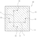
- FIG. 5 is a front view of a photomask on which a score for a change measurement test of a distance between scores is drawn.
- FIG. 1 is a schematic view of a photomask of the present invention
- FIG. 1 (a) is a front view
- FIG. 1 (b) is a cross-sectional view taken along line XX of FIG. 1 (a)
- Comprising: Fig.2 (a) is a front view of the photomask in which the several pattern was formed, FIG.2 (b) formed one pattern
- FIGS. 3 and 4 are process diagrams for explaining the photomask manufacturing method of the present invention.
- a photomask 10 of the present invention is used for photolithography for optically transferring a photomask pattern in the manufacture of an electric circuit board such as a semiconductor, a liquid crystal display or a printed wiring board, or in the etching of a metal foil.
- a photomask 10 of the present invention includes a base material 14 made of a film or sheet mainly composed of a polymer compound, and one of the base materials 14.
- the light shielding layer 16 is disposed on the surface (upper surface side in FIG. 1), and the frame 12 is disposed on the other surface (lower surface side in FIG. 1) of the base material 14.
- the photomask 10 of the present invention is characteristic in that the base material 14 is fixed to the frame 12 in a tensioned state in the atmosphere in which it is used and stored.
- the shape of the base material 14 and the frame 12 is usually a quadrangle or a rectangle. However, this shape is not particularly limited, and may be, for example, a circle or a polygon. Further, the frame 12 may be provided on both surfaces of the base material 14 in order to increase the mechanical strength of the photomask 10 and suppress deformation such as warpage. In that case, the frame 12 is provided on the light shielding layer 16. It may be provided.
- a film or sheet mainly composed of a polymer compound used as the base material 14 of such a photomask 10 needs to be optically transparent.
- optically transparent means that the light transmittance at the wavelength of the light source used for photolithography is high, and the light transmittance is 70% or more, preferably 80% or more, more preferably 85% or more. It is.
- the atmosphere in which the above-described photomask 10 is used or stored normally has a temperature range of 20 ° C. to 60 ° C. and a humidity range of 40% RH to 70% RH.
- the base material 14 needs to be fixed to the frame 12 made of a specific material in a state where tension is applied in the atmosphere.
- the base material 14 since the base material 14 needs to be fixed to the frame 12 under tension in an atmosphere where the photomask 10 is used or stored, a polymer compound used as the base material 14 is used. It is preferable that the thermal linear expansion coefficient of the film or sheet as the main component is larger than the humidity linear expansion coefficient.
- the temperature at the time of fixing is usually set to 50 ° C. or more, and the temperature difference from 50 ° C. This can be achieved by utilizing the shrinkage of the base material 14 (product of temperature difference and coefficient of thermal expansion).
- the shrinkage of the base material 14 due to the temperature difference between the fixed temperature and 50 ° C. is larger than the shrinkage due to the humidity change.
- the photomask 10 of the present invention it is preferable to use a base material 14 having a thermal linear expansion coefficient larger than the humidity linear expansion coefficient.
- the maximum change in humidity is 100% RH (0% RH to 100% RH). Therefore, the heat resistance temperature of the base material 14 may be exceeded and processing may not be possible.
- the thermal linear expansion coefficient is defined as a dimensional change with respect to a temperature of 1 ° C.
- the humidity linear expansion coefficient is defined as a dimensional change with respect to a humidity of 1% RH.
- the polymer compound used for the base material 14 of the present invention for example, an acrylic resin, a polyester resin, a polycarbonate resin, a cyclic olefin resin, or the like can be used.
- the cyclic olefin resin is preferable because of its high heat resistance and a wide selection range of the fixing temperature, low water absorption and low coefficient of linear expansion of humidity.
- cyclic olefin resin examples include, for example, a cyclic olefin resin, a trade name “ARTON” (manufactured by JSR Corporation), a trade name “ZEONEX” (manufactured by ZEON Corporation), and a trade name “ZEONOR” (ZEON CORPORATION). And a product name “Apel” (Mitsui Chemicals Co., Ltd.), and a polymer compound obtained by using a cyclic olefin compound represented by the following formula (1) as a monomer. Can be mentioned.
- R 1 to R 4 each independently represent a hydrogen atom; a halogen atom; a substituted or unsubstituted carbon atom which may have a linking group containing oxygen, nitrogen, sulfur or silicon 1 Represents a hydrocarbon group of ⁇ 15 or other monovalent organic group.
- R 1 and R 2 or R 3 and R 4 may be bonded to each other to form an alkylidene group
- R 1 and R 2 , R 3 and R 4, or R 2 and R 3 may be They may be bonded to each other to form a carbocycle or a heterocycle (these carbocycles or heterocycles may be monocyclic structures, or other rings may be condensed to form a polycyclic structure).
- the formed carbocyclic or heterocyclic ring may be an aromatic ring or a non-aromatic ring.
- X represents an integer of 0 to 3
- y represents 0 or 1.
- Specific examples of the cyclic olefin compound represented by the formula (1) include the compounds shown below.
- these cyclic olefin compounds may be used alone or in combination of two or more. Moreover, you may use together the compound copolymerizable with these monomers.
- the kind and amount of the cyclic olefin compound and copolymerizable compound constituting the monomer or monomer composition are appropriately selected depending on the properties required for the obtained cyclic olefin resin.
- cyclic olefin-based resins those having a glass transition temperature (Tg) of 80 ° C. or higher, preferably 100 ° C. or higher, more preferably 120 ° C. or higher have a fixing temperature when fixing the frame 12 and the substrate 14.
- Tg glass transition temperature
- cyclic olefin-based resin that can be used in the present invention is not limited to these examples.
- the thickness of the film or sheet mainly composed of the polymer compound used as the substrate 14 in the present invention is not particularly limited as long as the above conditions are satisfied, but is usually 0.01 mm to 50 mm, preferably 0.05 mm. It is ⁇ 30 mm, more preferably 0.1 mm to 15 mm.
- the thickness of the base material 14 is less than 0.01 mm, it may be too thin to reduce the strength of the photomask 10 and make it difficult to handle.
- the thickness of the base material 14 exceeds 50 mm, the weight of the photomask 10 increases, which may make handling difficult.
- the film or sheet mainly composed of the polymer compound used as the base material 14 is blended with an antioxidant, a coupling agent, an antistatic agent, a flame retardant, a dye, a pigment and the like as long as it is optically transparent. May be.
- a reinforcing material such as glass fiber, glass cloth or various fillers may be contained.
- the method for producing a film or sheet mainly composed of a polymer compound used as the substrate 14 in the present invention is not particularly limited, and known methods such as an injection molding method, a blow molding method, a melt extrusion method, and a solution casting method. It can manufacture by the method of. Further, it may be stretched.
- the frame 12 is preferably made of a material having a coefficient of thermal expansion of 35 ppm / ° C. or less, more preferably 30 ppm / ° C. or less, still more preferably 15 ppm / ° C. or less, and most preferably 10 ppm / ° C. or less.
- Examples of the material of the frame 12 include glass-based materials such as soda lime glass, Pyrex (registered trademark) glass, and quartz glass, aluminum, silicon, nickel, carbon steel, stainless steel (SUS304, SUS316, SUS410), and iron.
- Metallic materials such as nickel alloys (42 alloy), ceramics materials such as alumina, aluminum nitride, silicon carbide and silicon nitride, epoxy resins and polyester resins containing fillers such as glass fiber, silica, alumina and boron nitride, Examples thereof include composite resin materials such as polyimide resin and polycarbonate resin.
- glass-based materials, ceramic-based materials, and metal-based materials are preferable because they are substantially free from dimensional changes due to humidity, and metal-based materials are more preferable because they are excellent in workability.
- the thickness and width of the frame 12 of the photomask 10 in the present invention are not particularly limited as long as they are not deformed by the tension of the film or sheet mainly composed of the polymer compound to be fixed.
- the width is 100 mm and the width is 5 mm to 150 mm.
- the light shielding layer 16 used in the present invention a conventionally known one can be applied, and for example, it can be obtained by coating a silver salt photosensitive emulsion. Furthermore, it is also possible to use a photosensitive ink or paint obtained by blending a pigment or a dye with a photosensitive resin.
- the thickness of the light shielding layer 16 may be any thickness as long as the light transmittance of the light shielding portion is usually 1% or less, and is usually 2 to 10 ⁇ m.
- the light shielding layer 16 can be formed by providing a metal thin film by vapor deposition or the like.
- chromium or a multilayer film of chromium and chromium oxide is often used, but silicon, iron oxide, molybdenum silicite, or the like can also be used as a film material.
- the thickness of the light shielding layer 16 is as follows. Usually 80 to 150 nm.
- the light shielding layer 16 is usually provided on one surface of the base material, but does not prevent the light shielding layer 16 from being provided on both surfaces.
- a functional layer such as a protective layer, an antireflection layer, or an antistatic layer can be provided on the base material 14 or the light shielding layer 16.
- a functional layer may be provided by coating a liquid raw material, or may be provided by bonding a film having these functions.
- a plurality of types of patterns may be formed on one light shielding layer 16 and can be appropriately selected.
- the base material 14 is fixed in a tensioned state to the frame 12 made of a material having a thermal linear expansion coefficient of 35 ppm / ° C. or less in an atmosphere where it is used and stored. Therefore, there is no dimensional change associated with a humidity change, and the dimensional change associated with a temperature change can be significantly reduced as compared with a conventional photomask.
- a frame 12 made of a material having a thermal linear expansion coefficient of 35 ppm / ° C. or less is prepared.
- an adhesive is applied to one surface of the frame 12 (the upper surface in FIG. 3B).
- a base material 14 that is slightly larger than the frame 12 is bonded onto the frame 12 to which the adhesive is applied at room temperature.
- the adhesive is cured by heating at a temperature higher than the temperature at which the base material 14 is used and stored, usually 100 ° C. or higher, and the base material 14 is fixed to the frame 12. Then, when it cools to the temperature used or stored, the base material 14 will be fixed to the flame
- the light shielding layer 16 is provided on the surface of the base material 14 where the frame 12 is not adhered (the upper surface in FIG. 3C).
- the method of providing the light shielding layer 16 varies depending on the material of the light shielding layer 16. For example, in the case of a silver salt photosensitive emulsion, coating is performed using a known coater such as a roll coater or a slit coater, followed by drying.
- a known coater such as a roll coater or a slit coater
- a metal thin film such as a chromium / chromium oxide composite layer
- a resist layer for etching is usually further provided thereon.
- a liquid resist or a dry film resist may be used. Further, either a positive type or a negative type may be used.
- a pattern 20 that matches the desired pattern is formed on the light shielding layer 16 with a laser 18 or an electron beam, and then post-processing such as development is performed.
- a functional layer (not shown) having functions such as surface protection, antireflection, and antistatic may be further formed on the base material 14 and the light shielding layer 16. .
- the photomask 10 of the present invention is manufactured by the simple process as described above, and the base material 14 is used and stored in the frame 12 made of a material having a thermal linear expansion coefficient of 35 ppm / ° C. or less. Since it is fixed in a tensioned state in the atmosphere, there is almost no dimensional change associated with a change in humidity, and the dimensional change associated with a temperature change can be significantly reduced as compared with a conventional photomask.
- the photomask of the present invention has a special atmosphere for use or storage in the same way as a photomask using a substrate made of glass, in response to the recent demand for finer patterns and stricter accuracy. This can be dealt with without adjustment, and the manufacturing cost can be reduced.
- Example 1 First, a frame 12 made of 42 alloy (thermal linear expansion coefficient: 4 ppm, humidity linear expansion coefficient: 0), outer shape of 430 mm square, frame width of 30 mm, and thickness of 1.0 mm was prepared (FIG. 3A).
- thermosetting adhesive was applied to one surface of the frame 12, and a trade name “ARTON” (manufactured by JSR Corporation) (glass transition temperature: 171 ° C., thermal linear expansion on the adhesive-coated surface.
- the base material 14 made of a film of 450 mm square and 100 ⁇ m thickness obtained by the solution casting method using a rate of 62 ppm and a humidity linear expansion coefficient of 4 ppm is attached so that no slack occurs in an atmosphere of 25 ° C. and 55% RH. Combined.
- the adhesive was cured by heating at 160 ° C. for 5 hours, and the base material 14 was fixed to the frame 12 (FIG. 3B).
- the obtained frame 12 and the base material 14 fixed to the frame 12 were returned to an atmosphere of 25 ° C. and 55% RH, and the portion of the base material 14 that protruded from the frame 12 was cut with a cutter.
- the photomask precursor thus obtained was measured for measurement as shown in FIG. 5 using a laser drawing apparatus (DI-2080, manufactured by Pentax Co., Ltd.) in an atmosphere of 25 ° C. and 55% RH. 22 was drawn in four places on the base material 14 so that the distance L between the ratings was 350 mm, and then developed and dried to obtain a photomask (A-1).
- a photomask precursor was obtained in the same manner as in Example 1 except that a composite layer of chromium / chromium oxide having a thickness of 100 nm was deposited instead of coating / drying the silver salt photosensitive emulsion in providing the light shielding layer 16. It was.
- a negative resist (manufactured by JSR Corporation: THB-110N) is applied to the light shielding layer 16 of the photomask precursor thus obtained and dried, and then a laser drawing apparatus (DI-2080, manufactured by Pentax Corporation) is applied.
- the measurement score 22 is drawn at four locations on the base 14 so that the distance L between the scores is 350 mm, and then developed, etched, resist stripped, washed and dried to obtain a photomask ( A-2) was obtained.
- a photomask (B-1) using a silver salt gelatin emulsion as a light-shielding layer 16 was prepared in the same manner as in Example 1 except that the frame 12 was not provided.
- a photomask (B-2) was obtained in the same manner as in Example 2 except that the frame 12 was not provided, and a 430 mm square and a chromium / chromium oxide composite layer was used as the light shielding layer 16.
- the photomask (A-1) obtained in Example 1 was exposed to an atmosphere of “25 ° C., 55% RH” for 24 hours, and then the center was pierced with a household sewing needle in the same atmosphere to make a hole. As a result, it was confirmed that the base material 14 had been tensioned at once.
- the photomask (A-2) obtained in Example 2 was also “25 ° C., 20% RH”, “25 ° C., 55% RH”, “25 ° C., 80% RH” in the same manner as in Example 1.
- the center of the photomask was pierced with a household sewing needle, and a hole was formed. It was confirmed that the base material 14 was also tensioned. It was.
- the photomasks (A-1, A-2) fixed to the frame 12 with the base material 14 in a tensioned state have no dimensional change due to humidity change, and change in temperature. It was confirmed that the accompanying dimensional change was remarkably small as compared with the photomasks (B-1, B-2) without the frame 12.
- the photomasks (A-1, A-2) of Example 1 and Example 2 obtained by the manufacturing method of the present invention are in response to the recent demands for finer patterns and stricter required accuracy. This shows that the photomask using the base material 14 made of glass can be used without special adjustment of the atmosphere used or stored.
- the dimensional change of the photomask accompanying the temperature change is almost the same as the thermal linear expansion coefficient of the 42 alloy which is the material of the frame 12, and this is because the thermal linear expansion coefficient is further reduced in order to further reduce the dimensional change. This suggests that a small material should be used for the frame.
Landscapes
- Physics & Mathematics (AREA)
- General Physics & Mathematics (AREA)
- Preparing Plates And Mask In Photomechanical Process (AREA)
Abstract
[課題]ガラスを基材として用いなくても、近年のプリント配線基板のパターンの細線化や要求精度の厳格化に対応でき、かつ、ポリエステルフィルムを基材として用いた場合と同等の利便性を有するフォトマスクを提供すること。 [解決手段]高分子化合物を主成分とするフィルムまたはシートからなる基材と、前記基材の少なくとも一方の面に配設された遮光層と、前記基材の少なくとも一方の面に配設されたフレームと、から少なくとも構成されたフォトマスクであって、前記フォトマスクは、使用および保管される雰囲気において、前記基材が、前記フレームに張力のかかった状態で固定されている。
Description
半導体や液晶ディスプレイあるいはプリント配線基板などの電気回路基板の製造や金属箔のエッチング加工などの際に用いられるフォトマスクに関する。
従来より半導体や液晶ディスプレイあるいはプリント配線基板などの電気回路基板の製造や金属箔のエッチング加工などにおいて、マスクのパターンを光学的に転写するフォトリソグラフィーが広く用いられている。
このフォトリソグラフィーに用いられるマスクは、通常フォトマスクもしくはレチクルと称されることが多く、一般的には光学的に透明な基材と、この基材の表面に設けられた遮光層と、から構成されている。本発明においては、係るフォトマスクもしくはレチクルと称されるフォトリソグラフィーに用いられるマスクを「フォトマスク」と総称する。
なお、この光学的に透明な基材には、ポリエステルフィルムおよびソーダライムガラスや石英ガラスなどのガラスが、要求される特性に応じて適宜選択されて用いられている。
すなわち、プリント配線基板や金属箔のエッチング加工のように比較的パターンの線幅が大きく、位置や形状に関する要求精度が厳しくない場合には、ポリエステルフィルムが用いられることが多い。
一方、半導体や液晶ディスプレイのようにパターンの線幅が小さく、位置や形状に関する要求精度が厳しい場合には、ソーダライムガラスや石英ガラスなどのガラスが専ら用いられていた。
近年、携帯電話やデジタルカメラなどのプリント配線基板が搭載される最終製品は、小型化,薄肉化が急速に進んでおり、この結果、各種半導体や抵抗,コンデンサーといった電子部品の実装密度が上がり、パターンが細線化し、要求精度も厳しくなっている。
このため、従来のポリエステルフィルムでは、温度や湿度の変化により寸法変化が生じてしまい、パターンの細線化や要求精度の厳格化に対応できないという問題が生じていた。
特に天候などによって生ずる湿度の変化は、温度の変化に比べて大きく、ポリエステルフィルムを基材として用いたフォトマスクの精度や形状に大きな影響を与えるため、パターンの細線化や要求精度の厳格化に対応する上で、湿度の変化に伴う寸法変化の抑制が最大の問題であった。
このため、専ら半導体や液晶ディスプレイの製造に使用していたガラスを、プリント配線基板製造用の基材として用いる場合が多々発生している。
しかしながら、フォトマスクの基材としてガラスを用いた場合、ポリエステルフィルムと比べてコストアップするだけでなく、破損防止や重量増加に伴う作業性の低下あるいは保管場所確保が問題となる。
このため、ガラスよりも安価なポリエステルフィルムを基材とするフォトマスクにおいて、温度や湿度の変化に伴う寸法変化を低減させるため、従来のポリエステルフィルムからなる基材のフォトマスクに他の透明フィルムを積層して、寸法変化を少なくする技術が特許文献1および特許文献2に開示されている。
しかしながら、特許文献1および特許文献2に記載されたような透明フィルムを積層したポリエステルフィルムを用いた基板は、ガラスを用いた基材と比べてしまうと、やはり温度や湿度の変化に伴う寸法変化が相変わらず大きく、近年のパターンの細線化や要求精度の厳格化の要求に必ずしも十分対応できるものではなかった。
本発明はこのような現状に鑑み、ガラスを基材として用いなくても、近年のプリント配線基板のパターンの細線化や要求精度の厳格化に対応でき、かつ、ポリエステルフィルムを基材として用いた場合と同等の利便性を有するフォトマスクを提供することを目的とする。
本発明は、前述したような従来技術における課題および目的を達成するために発明されたものであって、
本発明のフォトマスクは、
高分子化合物を主成分とするフィルムまたはシートからなる基材と、
前記基材の少なくとも一方の面に配設された遮光層と、
前記基材の少なくとも一方の面に配設されたフレームと、
から少なくとも構成されたフォトマスクであって、
前記フォトマスクは、
使用および保管される雰囲気において、
前記基材が、前記フレームに張力のかかった状態で固定されていることを特徴とする。
本発明のフォトマスクは、
高分子化合物を主成分とするフィルムまたはシートからなる基材と、
前記基材の少なくとも一方の面に配設された遮光層と、
前記基材の少なくとも一方の面に配設されたフレームと、
から少なくとも構成されたフォトマスクであって、
前記フォトマスクは、
使用および保管される雰囲気において、
前記基材が、前記フレームに張力のかかった状態で固定されていることを特徴とする。
このように基材が張力のかかった状態でフレームに固定されていれば、湿度変化に伴う寸法変化が殆どなく、温度変化に伴う寸法変化も従来のフォトマスクと比べて著しく小さくすることができる。
このため、本発明のフォトマスクであれば、近年のパターンの細線化や要求精度の厳格化の要求に対して、ガラスからなる基材を用いたフォトマスクと同様に、使用もしくは保管される雰囲気を特別に調整しなくても対応することができ、製造コストを削減することができる。
また、本発明のフォトマスクは、
前記フレームが、熱線膨張率35ppm/℃以下の素材からなることを特徴とする。
前記フレームが、熱線膨張率35ppm/℃以下の素材からなることを特徴とする。
このような熱線膨張率の素材からなるフレームを用いたフォトマスクであれば、湿度変化に伴う寸法変化がなく、温度変化に伴う寸法変化も従来のフォトマスクと比べて小さいため、使用もしくは保管される雰囲気を特別に調整しなくても対応することができ、製造コストを削減することができる。
また、本発明のフォトマスクは、
前記基材は、熱線膨張率が湿度線膨張率より大きいことを特徴とする。
前記基材は、熱線膨張率が湿度線膨張率より大きいことを特徴とする。
このように基材の熱線膨張率が湿度線膨張率よりも大きいと、使用および保管される雰囲気での湿度変化に伴う寸法変化に対して、常に張力を保持できるようにするために必要なフレームの固定温度を広く設定でき、加工条件の選択肢が広がる。
また、本発明のフォトマスクは、
前記基材が、環状オレフィン系樹脂を主成分とすることを特徴とする。
前記基材が、環状オレフィン系樹脂を主成分とすることを特徴とする。
このように環状オレフィン系樹脂を主成分とする基材であれば、耐熱性が高いため固定温度の選択幅が広く、また吸水性が低く湿度線膨張率が小さいため好適である。
本発明によれば、ガラスを基材として用いなくても、近年のプリント配線基板のパターンの細線化や要求精度の厳格化に対応でき、かつ、ポリエステルフィルムを基材として用いた場合と同等の利便性を有するフォトマスクを提供することができる。
以下、本発明の実施の形態について、図面に基づいてより詳細に説明する。
図1は、本発明のフォトマスクの概略図であって、図1(a)は正面図、図1(b)は図1(a)のX-X線による断面図、図2は、本発明のフォトマスクに形成されるパターンについて説明するための説明図であって、図2(a)は複数のパターンが形成されたフォトマスクの正面図、図2(b)は1つのパターンが形成されたフォトマスクの正面図、図3および図4は、本発明のフォトマスクの製造方法を説明するための工程図である。
本発明のフォトマスクは、半導体や液晶ディスプレイあるいはプリント配線基板などの電気回路基板の製造や金属箔のエッチング加工などにおいて、フォトマスクのパターンを光学的に転写するフォトリソグラフィーに用いられるものである。
<フォトマスク10>
図1(a)および図1(b)に示したように、本発明のフォトマスク10は、高分子化合物を主成分とするフィルムまたはシートからなる基材14と、この基材14の一方の面(図1では上面側)に配設された遮光層16と、基材14の他方の面(図1では下面側)に配設されたフレーム12と、から構成されている。
<フォトマスク10>
図1(a)および図1(b)に示したように、本発明のフォトマスク10は、高分子化合物を主成分とするフィルムまたはシートからなる基材14と、この基材14の一方の面(図1では上面側)に配設された遮光層16と、基材14の他方の面(図1では下面側)に配設されたフレーム12と、から構成されている。
そして、本発明のフォトマスク10においては、使用および保管される雰囲気において、基材14が、フレーム12に張力のかかった状態で固定されている点で特徴的である。
ここで、基材14やフレーム12の形状としては通常は四角形または長方形である。しかしながらこの形状は特に限定されるものではなく、例えば円形、多角形であっても良いものである。また、フレーム12は、フォトマスク10の機械強度を高めたり反りなどの変形を抑制するために、基材14の両面に設けられていても良く、その場合、遮光層16の上にフレーム12が設けられていても良い。
このようなフォトマスク10の基材14として用いられる高分子化合物を主材とするフィルムまたはシートは、光学的に透明であることが必要である。
ここで、光学的に透明とは、フォトリソグラフィーに用いられる光源の波長における光線透過率が高いことを意味し、光線透過率としては70%以上、好ましくは80%以上、さらに好ましくは85%以上である。
また、上記したフォトマスク10が使用もしくは保管される雰囲気とは、通常、温度として20℃~60℃、湿度として40%RH~70%RHの範囲である。もちろん、この範囲外の場合には、その雰囲気において基材14が張力のかかった状態で特定の素材からなるフレーム12に固定されている必要がある。
また、本発明においては、フォトマスク10が使用もしくは保管される雰囲気において、基材14が張力のかかった状態でフレーム12に固定されている必要があるので、基材14として用いる高分子化合物を主成分とするフィルムまたはシートの熱線膨張率が、湿度線膨張率より大きいことが好ましい。
すなわち、例えば50℃において基材14を張力のかかった状態でフレーム12に固定するには、通常、固定時の温度(固定温度)を50℃以上に設定し、50℃との温度差に起因する基材14の収縮(温度差と熱線膨張率の積)を利用することで可能となる。
しかしながら、湿度変化があっても基材14に張力のかかった状態を維持するためには、固定温度と50℃との温度差に起因する基材14の収縮を、湿度変化による収縮よりも大きくしなければならない。
このため本発明のフォトマスク10では、用いられる基材14において、熱線膨張率が湿度線膨張率よりも大きな基材14を用いることが好ましい。
熱線膨張率の絶対値が湿度線膨張率の絶対値よりも大きくない場合には、湿度変化は最大100%RH(0%RH~100%RH)なので、固定温度を150℃以上にしなければならず、基材14の耐熱温度を超えてしまって加工ができなくなる場合が生じてしまうこととなる。
なお、本発明では熱線膨張率は温度1℃に対する寸法変化、湿度線膨張率は湿度1%RHに対する寸法変化と定義している。
ここで、本発明の基材14に用いられる高分子化合物としては、例えばアクリル樹脂、ポリエステル樹脂、ポリカーボネート樹脂、環状オレフィン系樹脂などを用いることができる。
これらの中で、環状オレフィン系樹脂が、耐熱性が高いため固定温度の選択幅が広く、また、吸水性が低く湿度線膨張率が小さいため好ましい。
係る環状オレフィン系樹脂の具体例としては、例えば環状オレフィン系樹脂、商品名「ARTON」(JSR株式会社製)、商品名「ZEONEX」(日本ゼオン株式会社製)、商品名「ZEONOR」(日本ゼオン株式会社製)、商品名「アペル」(三井化学株式会社製)などを挙げることができ、また下記式(1)で表される環状オレフィン系化合物を単量体として用いて得られる高分子化合物を挙げることができる。

[式(1)中、R1~R4は、各々独立に水素原子;ハロゲン原子;酸素、窒素、イオウまたはケイ素を含む連結基を有していてもよい置換または非置換の炭素原子数1~15の炭化水素基、もしくはその他の1価の有機基を表す。
ここで、R1とR2もしくはR3とR4は、相互に結合してアルキリデン基を形成していてもよく、R1とR2、R3とR4またはR2とR3とが相互に結合して炭素環または複素環(これらの炭素環または複素環は単環構造でもよいし、他の環が縮合して多環構造を形成してもよい。)を形成してもよい。
形成される炭素環または複素環は芳香環でもよいし非芳香環でもよい。また、xは0~3の整数、yは0または1を表す。]
式(1)で表される環状オレフィン系化合物の具体例としては、例えば以下に示す化合物が例示できる。
式(1)で表される環状オレフィン系化合物の具体例としては、例えば以下に示す化合物が例示できる。
ビシクロ[2.2.1]ヘプト-2-エン、
5-メチル-ビシクロ[2.2.1]ヘプト-2-エン、
5-エチル-ビシクロ[2.2.1]ヘプト-2-エン、
5-シクロヘキシル-ビシクロ[2.2.1]ヘプト-2-エン、
5-フェニル-ビシクロ[2.2.1]ヘプト-2-エン、
5-(4-ビフェニル)-ビシクロ[2.2.1]ヘプト-2-エン、
5-メトキシカルボニル-ビシクロ[2.2.1]ヘプト-2-エン、
5-フェノキシカルボニル-ビシクロ[2.2.1]ヘプト-2-エン、
5-フェノキシエチルカルボニル-ビシクロ[2.2.1]ヘプト-2-エン、
5-フェニルカルボニルオキシ-ビシクロ[2.2.1]ヘプト-2-エン、
5-メチル-5-メトキシカルボニル-ビシクロ[2.2.1]ヘプト-2-エン、
5-メチル-5-フェノキシカルボニル-ビシクロ[2.2.1]ヘプト-2-エン、
5-メチル-5-フェノキシエチルカルボニル-ビシクロ[2.2.1]ヘプト-2-エン、
5-ビニル-ビシクロ[2.2.1]ヘプト-2-エン、
5-エチリデン-ビシクロ[2.2.1]ヘプト-2-エン、
5,5-ジメチル-ビシクロ[2.2.1]ヘプト-2-エン、
5,6-ジメチル-ビシクロ[2.2.1]ヘプト-2-エン、
5-フルオロ-ビシクロ[2.2.1]ヘプト-2-エン、
5-クロロ-ビシクロ[2.2.1]ヘプト-2-エン、
5-ブロモ-ビシクロ[2.2.1]ヘプト-2-エン、
5,6-ジフルオロ-ビシクロ[2.2.1]ヘプト-2-エン、
5,6-ジクロロ-ビシクロ[2.2.1]ヘプト-2-エン、
5,6-ジブロモ-ビシクロ[2.2.1]ヘプト-2-エン、
5-ヒドロキシ-ビシクロ[2.2.1]ヘプト-2-エン、
5-ヒドロキシエチル-ビシクロ[2.2.1]ヘプト-2-エン、
5-シアノ-ビシクロ[2.2.1]ヘプト-2-エン、
5-アミノ-ビシクロ[2.2.1]ヘプト-2-エン、
トリシクロ[4.3.0.12,5]デカ-3-エン、
トリシクロ[4.4.0.12,5]ウンデカ-3-エン、
7-メチル-トリシクロ[4.3.0.12,5]デカ-3-エン、
7-エチル-トリシクロ[4.3.0.12,5]デカ-3-エン、
7-シクロヘキシル-トリシクロ[4.3.0.12,5]デカ-3-エン、
7-フェニル-トリシクロ[4.3.0.12,5]デカ-3-エン、
7-(4-ビフェニル)-トリシクロ[4.3.0.12,5]デカ-3-エン、
7,8-ジメチル-トリシクロ[4.3.0.12,5]デカ-3-エン、
7,8,9-トリメチル-トリシクロ[4.3.0.12,5]デカ-3-エン、
8-メチル-トリシクロ[4.4.0.12,5]ウンデカ-3-エン、
8-フェニル-トリシクロ[4.4.0.12,5]ウンデカ-3-エン、
7-フルオロ-トリシクロ[4.3.0.12,5]デカ-3-エン、
7-クロロ-トリシクロ[4.3.0.12,5]デカ-3-エン、
7-ブロモ-トリシクロ[4.3.0.12,5]デカ-3-エン、
7,8-ジクロロ-トリシクロ[4.3.0.12,5]デカ-3-エン、
7,8,9-トリクロロ-トリシクロ[4.3.0.12,5]デカ-3-エン、
7-クロロメチル-トリシクロ[4.3.0.12,5]デカ-3-エン、
7-ジクロロメチル-トリシクロ[4.3.0.12,5]デカ-3-エン、
7-トリクロロメチル-トリシクロ[4.3.0.12,5]デカ-3-エン、
7-ヒドロキシ-トリシクロ[4.3.0.12,5]デカ-3-エン、
7-シアノ-トリシクロ[4.3.0.12,5]デカ-3-エン、
7-アミノ-トリシクロ[4.3.0.12,5]デカ-3-エン、
テトラシクロ[4.4.0.12,5.17,10]ドデカ-3-エン、
ペンタシクロ[7.4.0.12,5.18,11.07,12]ペンタデカ-3-エン、
ヘキサシクロ[8.4.0.12,5.17,14.19,12.08,13]ヘプタデカ-3-エン、
8-メチル-テトラシクロ[4.4.0.12,5.17,10]ドデカ-3-エン、
8-エチル-テトラシクロ[4.4.0.12,5.17,10]ドデカ-3-エン、
8-シクロヘキシル-テトラシクロ[4.4.0.12,5.17,10]ドデカ-3-エン、
8-フェニル-テトラシクロ[4.4.0.12,5.17,10]ドデカ-3-エン、
8-(4-ビフェニル)-テトラシクロ[4.4.0.12,5.17,10]ドデカ-3-エン、
8-メトキシカルボニル-テトラシクロ[4.4.0.12,5.17,10]ドデカ-3-エン、
8-フェノキシカルボニル-テトラシクロ[4.4.0.12,5.17,10]ドデカ-3-エン、
8-フェノキシエチルカルボニル-テトラシクロ[4.4.0.12,5.17,10]ドデカ-3-エン、
8-フェニルカルボニルオキシ-テトラシクロ[4.4.0.12,5.17,10]ドデカ-3-エン、
8-メチル-8-メトキシカルボニル-テトラシクロ[4.4.0.12,5.17,10]ドデカ-3-エン、
8-メチル-8-フェノキシカルボニル-テトラシクロ[4.4.0.12,5.17,10]ドデカ-3-エン、
8-メチル-8-フェノキシエチルカルボニル-テトラシクロ[4.4.0.12,5.17,10]ドデカ-3-エン、
8-ビニル-テトラシクロ[4.4.0.12,5.17,10]ドデカ-3-エン、
8-エチリデン-テトラシクロ[4.4.0.12,5.17,10]ドデカ-3-エン、
8,8-ジメチル-テトラシクロ[4.4.0.12,5.17,10]ドデカ-3-エン、
8,9-ジメチル-テトラシクロ[4.4.0.12,5.17,10]ドデカ-3-エン、
8-フルオロ-テトラシクロ[4.4.0.12,5.17,10]ドデカ-3-エン、
8-クロロ-テトラシクロ[4.4.0.12,5.17,10]ドデカ-3-エン、
8-ブロモ-テトラシクロ[4.4.0.12,5.17,10]ドデカ-3-エン、
8,8-ジクロロ-テトラシクロ[4.4.0.12,5.17,10]ドデカ-3-エン、
8,9-ジクロロ-テトラシクロ[4.4.0.12,5.17,10]ドデカ-3-エン、
8,8,9,9-テトラクロロ-テトラシクロ[4.4.0.12,5.17,10]ドデカ-3-エン、
8-ヒドロキシ-テトラシクロ[4.4.0.12,5.17,10]ドデカ-3-エン、
8-ヒドロキシエチル-テトラシクロ[4.4.0.12,5.17,10]ドデカ-3-エン、
8-メチル-8-ヒドロキシエチル-テトラシクロ[4.4.0.12,5.17,10]ドデカ-3-エン、
8-シアノ-テトラシクロ[4.4.0.12,5.17,10]ドデカ-3-エン、
8-アミノ-テトラシクロ[4.4.0.12,5.17,10]ドデカ-3-エン。
5-メチル-ビシクロ[2.2.1]ヘプト-2-エン、
5-エチル-ビシクロ[2.2.1]ヘプト-2-エン、
5-シクロヘキシル-ビシクロ[2.2.1]ヘプト-2-エン、
5-フェニル-ビシクロ[2.2.1]ヘプト-2-エン、
5-(4-ビフェニル)-ビシクロ[2.2.1]ヘプト-2-エン、
5-メトキシカルボニル-ビシクロ[2.2.1]ヘプト-2-エン、
5-フェノキシカルボニル-ビシクロ[2.2.1]ヘプト-2-エン、
5-フェノキシエチルカルボニル-ビシクロ[2.2.1]ヘプト-2-エン、
5-フェニルカルボニルオキシ-ビシクロ[2.2.1]ヘプト-2-エン、
5-メチル-5-メトキシカルボニル-ビシクロ[2.2.1]ヘプト-2-エン、
5-メチル-5-フェノキシカルボニル-ビシクロ[2.2.1]ヘプト-2-エン、
5-メチル-5-フェノキシエチルカルボニル-ビシクロ[2.2.1]ヘプト-2-エン、
5-ビニル-ビシクロ[2.2.1]ヘプト-2-エン、
5-エチリデン-ビシクロ[2.2.1]ヘプト-2-エン、
5,5-ジメチル-ビシクロ[2.2.1]ヘプト-2-エン、
5,6-ジメチル-ビシクロ[2.2.1]ヘプト-2-エン、
5-フルオロ-ビシクロ[2.2.1]ヘプト-2-エン、
5-クロロ-ビシクロ[2.2.1]ヘプト-2-エン、
5-ブロモ-ビシクロ[2.2.1]ヘプト-2-エン、
5,6-ジフルオロ-ビシクロ[2.2.1]ヘプト-2-エン、
5,6-ジクロロ-ビシクロ[2.2.1]ヘプト-2-エン、
5,6-ジブロモ-ビシクロ[2.2.1]ヘプト-2-エン、
5-ヒドロキシ-ビシクロ[2.2.1]ヘプト-2-エン、
5-ヒドロキシエチル-ビシクロ[2.2.1]ヘプト-2-エン、
5-シアノ-ビシクロ[2.2.1]ヘプト-2-エン、
5-アミノ-ビシクロ[2.2.1]ヘプト-2-エン、
トリシクロ[4.3.0.12,5]デカ-3-エン、
トリシクロ[4.4.0.12,5]ウンデカ-3-エン、
7-メチル-トリシクロ[4.3.0.12,5]デカ-3-エン、
7-エチル-トリシクロ[4.3.0.12,5]デカ-3-エン、
7-シクロヘキシル-トリシクロ[4.3.0.12,5]デカ-3-エン、
7-フェニル-トリシクロ[4.3.0.12,5]デカ-3-エン、
7-(4-ビフェニル)-トリシクロ[4.3.0.12,5]デカ-3-エン、
7,8-ジメチル-トリシクロ[4.3.0.12,5]デカ-3-エン、
7,8,9-トリメチル-トリシクロ[4.3.0.12,5]デカ-3-エン、
8-メチル-トリシクロ[4.4.0.12,5]ウンデカ-3-エン、
8-フェニル-トリシクロ[4.4.0.12,5]ウンデカ-3-エン、
7-フルオロ-トリシクロ[4.3.0.12,5]デカ-3-エン、
7-クロロ-トリシクロ[4.3.0.12,5]デカ-3-エン、
7-ブロモ-トリシクロ[4.3.0.12,5]デカ-3-エン、
7,8-ジクロロ-トリシクロ[4.3.0.12,5]デカ-3-エン、
7,8,9-トリクロロ-トリシクロ[4.3.0.12,5]デカ-3-エン、
7-クロロメチル-トリシクロ[4.3.0.12,5]デカ-3-エン、
7-ジクロロメチル-トリシクロ[4.3.0.12,5]デカ-3-エン、
7-トリクロロメチル-トリシクロ[4.3.0.12,5]デカ-3-エン、
7-ヒドロキシ-トリシクロ[4.3.0.12,5]デカ-3-エン、
7-シアノ-トリシクロ[4.3.0.12,5]デカ-3-エン、
7-アミノ-トリシクロ[4.3.0.12,5]デカ-3-エン、
テトラシクロ[4.4.0.12,5.17,10]ドデカ-3-エン、
ペンタシクロ[7.4.0.12,5.18,11.07,12]ペンタデカ-3-エン、
ヘキサシクロ[8.4.0.12,5.17,14.19,12.08,13]ヘプタデカ-3-エン、
8-メチル-テトラシクロ[4.4.0.12,5.17,10]ドデカ-3-エン、
8-エチル-テトラシクロ[4.4.0.12,5.17,10]ドデカ-3-エン、
8-シクロヘキシル-テトラシクロ[4.4.0.12,5.17,10]ドデカ-3-エン、
8-フェニル-テトラシクロ[4.4.0.12,5.17,10]ドデカ-3-エン、
8-(4-ビフェニル)-テトラシクロ[4.4.0.12,5.17,10]ドデカ-3-エン、
8-メトキシカルボニル-テトラシクロ[4.4.0.12,5.17,10]ドデカ-3-エン、
8-フェノキシカルボニル-テトラシクロ[4.4.0.12,5.17,10]ドデカ-3-エン、
8-フェノキシエチルカルボニル-テトラシクロ[4.4.0.12,5.17,10]ドデカ-3-エン、
8-フェニルカルボニルオキシ-テトラシクロ[4.4.0.12,5.17,10]ドデカ-3-エン、
8-メチル-8-メトキシカルボニル-テトラシクロ[4.4.0.12,5.17,10]ドデカ-3-エン、
8-メチル-8-フェノキシカルボニル-テトラシクロ[4.4.0.12,5.17,10]ドデカ-3-エン、
8-メチル-8-フェノキシエチルカルボニル-テトラシクロ[4.4.0.12,5.17,10]ドデカ-3-エン、
8-ビニル-テトラシクロ[4.4.0.12,5.17,10]ドデカ-3-エン、
8-エチリデン-テトラシクロ[4.4.0.12,5.17,10]ドデカ-3-エン、
8,8-ジメチル-テトラシクロ[4.4.0.12,5.17,10]ドデカ-3-エン、
8,9-ジメチル-テトラシクロ[4.4.0.12,5.17,10]ドデカ-3-エン、
8-フルオロ-テトラシクロ[4.4.0.12,5.17,10]ドデカ-3-エン、
8-クロロ-テトラシクロ[4.4.0.12,5.17,10]ドデカ-3-エン、
8-ブロモ-テトラシクロ[4.4.0.12,5.17,10]ドデカ-3-エン、
8,8-ジクロロ-テトラシクロ[4.4.0.12,5.17,10]ドデカ-3-エン、
8,9-ジクロロ-テトラシクロ[4.4.0.12,5.17,10]ドデカ-3-エン、
8,8,9,9-テトラクロロ-テトラシクロ[4.4.0.12,5.17,10]ドデカ-3-エン、
8-ヒドロキシ-テトラシクロ[4.4.0.12,5.17,10]ドデカ-3-エン、
8-ヒドロキシエチル-テトラシクロ[4.4.0.12,5.17,10]ドデカ-3-エン、
8-メチル-8-ヒドロキシエチル-テトラシクロ[4.4.0.12,5.17,10]ドデカ-3-エン、
8-シアノ-テトラシクロ[4.4.0.12,5.17,10]ドデカ-3-エン、
8-アミノ-テトラシクロ[4.4.0.12,5.17,10]ドデカ-3-エン。
なお、これら環状オレフィン系化合物は1種単独で用いてもよいし、2種以上を併用してもよい。また、これら単量体と共重合可能な化合物を併用してもよい。
単量体あるいは単量体組成物を構成する環状オレフィン系化合物や共重合可能な化合物の種類および量は、得られる環状オレフィン系樹脂に求められる特性により適宜選択される。
これら環状オレフィン系樹脂の中でも、ガラス転移温度(Tg)が80℃以上、好ましくは100℃以上、さらに好ましくは120℃以上のものは、フレーム12と基材14との固定の際、固定温度を高く設定できるので好ましく、吸水率が0.5%以下、好ましくは0.3%以下、さらに好ましくは0.25%以下のものは、湿度線膨張率が小さいので好ましい。
なお、本発明で用いることのできる環状オレフィン系樹脂が、これらの例示に限定されるものではないことはもちろんである。
本発明において基材14として用いる高分子化合物を主成分とするフィルムまたはシートの厚みは、上記条件を満たす限りにおいて特に限定されるものではないが、通常0.01mm~50mm、好ましくは0.05mm~30mm、さらに好ましくは0.1mm~15mmである。
ここで基材14の厚みが0.01mm未満になると、薄すぎてフォトマスク10の強度が低下し取扱いが困難になる場合がある。
一方、基材14の厚みが50mmを越えて厚くなると、フォトマスク10の重量が増大し、取扱いが困難になる場合がある。
本発明において基材14として用いる高分子化合物を主成分とするフィルムまたはシートは、光学的に透明である限り、酸化防止剤、カップリング剤、帯電防止剤、難燃剤、色素、顔料などが配合されていても良い。
また、光学的に透明である限り、ガラス繊維、ガラスクロスあるいは各種フィラーなどの補強材が含まれていても良い。
本発明において基材14として用いる高分子化合物を主成分とするフィルムまたはシートの製造方法は、特に限定されるものではなく、射出成形法、ブロー成形法、溶融押出法、溶液キャスト法などの公知の方法で製造できる。また、延伸加工されていても良い。
またフレーム12は、熱線膨張率35ppm/℃以下の素材を用いることが好ましく、より好ましくは30ppm/℃以下、さらに好ましくは15ppm/℃以下、最も好ましくは10ppm/℃以下である。
このようなフレーム12の素材としては、例えばソーダライムガラス、パイレックス(登録商標)ガラス、石英ガラスなどのガラス系素材、アルミニウム、シリコン、ニッケル、炭素鋼、ステンレス鋼(SUS304、SUS316、SUS410)、鉄ニッケル合金(42アロイ)などの金属系素材、アルミナ、窒化アルミニウム、炭化珪素、窒化珪素などのセラミクス系素材、ガラス繊維、シリカ、アルミナ、ボロンナイトライドなどのフィラーを配合したエポキシ樹脂、ポリエステル樹脂、ポリイミド樹脂、ポリカーボネート樹脂などの複合樹脂系素材などが挙げられる。これらの中でガラス系素材、セラミクス系素材および金属系素材は、実質的に湿度による寸法変化がなく好ましく、さらに金属系素材は加工性にも優れるのでより好ましい。
本発明におけるフォトマスク10のフレーム12の厚みや幅は、固定される高分子化合物を主成分とするフィルムまたはシートの張力により変形しない限り、特に制限はないが、通常、厚みは0.05mm~100mm、幅は5mm~150mmである。
また、本発明において使用される遮光層16としては、従来より公知のものが適用でき、例えば銀塩感光乳剤を塗工して得られる。さらに、感光性樹脂に顔料や染料を配合して得られる感光性のインクや塗料を用いることも可能である。なお、遮光層16の厚さとしては、遮光部分の光透過率を通常1%以下にできる厚みであれば良く、通常2~10μmである。
また、蒸着などにより金属系薄膜を設けて遮光層16とすることもできる。この場合、クロムもしくはクロムと酸化クロムの複層膜が用いられることが多いが、シリコンや酸化鉄、モリブデンシリサイトなども膜材として用いることができ、この場合における遮光層16の厚さとしては通常80~150nmである。
なお、係る遮光層16は、通常基材の一方の面に設けられるが、両面に設けることを妨げるものではない。
さらに、本発明においては、基材14や遮光層16に、保護層,反射防止層,帯電防止層などの機能層(図示せず)を設けることもできる。係る機能層は、液状原料をコーティングして設けてもよいし、これらの機能を有するフィルムを貼合して設けてもよい。
また、遮光層16においては、図2(a)に示したフォトマスク10aように、複数のパターン20aが一つの遮光層16に形成されていても、図2(b)に示したフォトマスク10bのように、一つのパターン20bが一つの遮光層16に形成されていてもよい。また、複数種類のパターンが一つの遮光層16に形成されていてもよく、適宜選択が可能なものである。
上記したように本発明のフォトマスク10は、使用および保管される雰囲気において、基材14が、熱線膨張率35ppm/℃以下の素材からなるフレーム12に、張力のかかった状態で固定されているため、湿度変化に伴う寸法変化がなく、温度変化に伴う寸法変化も従来のフォトマスクと比べて著しく小さくすることができる。
このため、近年のパターンの細線化や要求精度の厳格化の要求に対して、ガラスからなる基材を用いたフォトマスクと同様に、使用もしくは保管される雰囲気を特別に調整しなくても対応することができ、製造コストを削減することができる。
<フォトマスク10の製造方法>
上記したフォトマスク10の製造方法について、以下説明する。
<フォトマスク10の製造方法>
上記したフォトマスク10の製造方法について、以下説明する。
本発明のフォトマスク10の製造方法では、まず図3(a)に示したように、熱線膨張率35ppm/℃以下の素材からなるフレーム12を準備する。
次いで、図3(b)に示したように、フレーム12の一方の面(図3(b)では上面)に接着剤を塗布する。
さらに、常温下において、接着剤が塗布されたフレーム12上に、このフレーム12より一回り大きな基材14を貼合する。
そして、フレーム12上に基材14を貼合した後、使用および保管する温度より高い温度、通常100℃以上で加熱して接着剤を硬化し、基材14をフレーム12に固定する。その後、使用または保管する温度まで冷却すると、基材14は張力のかかった状態でフレーム12に固定される。
さらに、図3(c)に示したように、基材14のフレーム12が接着されていない面(図3(c)では上面)に遮光層16を設ける。
遮光層16の設け方は遮光層16の材質により異なるが、例えば、銀塩感光乳剤の場合はロールコーターやスリットコーターなど公知のコーターを用いて塗工し、その後乾燥することで設ける。
一方、クロム・酸化クロム複合層などの金属系薄膜の場合には蒸着により設ける。なお、金属系薄膜の場合には、通常、さらにその上にエッチングのためのレジスト層を設ける。係るレジスト層を設けるにあたっては、液状レジストを用いても良いしドライフィルムレジストを用いても良い。また、ポジ型、ネガ型いずれであっても良い。
次いで、図4(a)に示したように、遮光層16にレーザー18や電子線などで所望のパターンに合わせたパターン20を形成し、その後現像などの後処理を実施する。
これにより、図4(b)に示したようなフォトマスク10を得ることができる。
なお、このようにして製造されるフォトマスク10は、さらに基材14や遮光層16に、表面保護,反射防止,帯電防止などの機能を有する機能層(図示せず)を形成しても良い。
このように、本発明のフォトマスク10は、上記したような簡単な工程で製造されるものであり、基材14が、熱線膨張率35ppm/℃以下の素材からなるフレーム12に、使用および保管される雰囲気において張力のかかった状態で固定されているため、湿度変化に伴う寸法変化が殆どなく、温度変化に伴う寸法変化も従来のフォトマスクと比べて著しく小さくすることができる。
このため本発明のフォトマスクは、近年のパターンの細線化や要求精度の厳格化の要求に対して、ガラスからなる基材を用いたフォトマスクと同様に、使用もしくは保管される雰囲気を特別に調整しなくても対応することができ、製造コストを削減することができる。
以上、本発明の好ましい形態について説明したが、本発明は上記の形態および製造方法に限定されるものではなく、本発明の目的を逸脱しない範囲での種々の変更が可能なものである。
[実施例1]
まず、42アロイ製(熱線膨張率:4ppm、湿度線膨張率:0)、外形430mm角、枠幅30mm、厚み1.0mmのフレーム12を準備した(図3(a))。
まず、42アロイ製(熱線膨張率:4ppm、湿度線膨張率:0)、外形430mm角、枠幅30mm、厚み1.0mmのフレーム12を準備した(図3(a))。
次いでこのフレーム12の一の面にエポキシ系熱硬化性接着剤を塗工し、この接着剤塗工面上に、商品名「ARTON」(JSR株式会社製)(ガラス転移温度:171℃、熱線膨張率:62ppm、湿度線膨張率:4ppm)を用い溶液キャスト法により得られた450mm角、厚み100μmのフィルムからなる基材14を、25℃、55%RHの雰囲気において弛みが生じないように貼合した。
次いで、160℃で5時間加熱して接着剤を硬化させ、基材14をフレーム12に固定した(図3(b))。
得られたフレーム12およびフレーム12に固定された基材14を25℃、55%RHの雰囲気に戻し、基材14のフレーム12からはみ出した部分をカッターにてカットした。
その後、基材14のフレーム12が接着されていない面に、銀塩感光乳剤を塗工した。
その後で乾燥して厚み5μmの遮光層16を設けてフォトマスク原版を得た(図3(c))。
このようにして得られたフォトマスク原版に、25℃、55%RHの雰囲気において、レーザー描画装置(ペンタックス株式会社製、DI-2080)を用いて、図5に示したように測定用の評点22を、評点間距離Lが350mmとなるように基材14の上下左右の4箇所に描画し、その後、現像,乾燥してフォトマスク(A-1)を得た。
[実施例2]
遮光層16を設けるにあたり、銀塩感光乳剤の塗工・乾燥の代わりに、厚み100nmのクロム・酸化クロムの複合層を蒸着加工したこと以外は、実施例1と同様にしてフォトマスク原版を得た。
[実施例2]
遮光層16を設けるにあたり、銀塩感光乳剤の塗工・乾燥の代わりに、厚み100nmのクロム・酸化クロムの複合層を蒸着加工したこと以外は、実施例1と同様にしてフォトマスク原版を得た。
このようにして得られたフォトマスク原版の遮光層16に、ネガレジスト(JSR株式会社製:THB-110N)を塗工・乾燥し、次いでレーザー描画装置(ペンタックス株式会社製、DI-2080)を用いて、測定用の評点22を、評点間距離Lが350mmとなるように基材14の上下左右の4箇所に描画し、その後、現像,エッチング,レジスト剥離,洗浄,乾燥してフォトマスク(A-2)を得た。
[比較例1]
フレーム12がないこと以外は実施例1と同様にして、430mm角、遮光層16として銀塩ゼラチン乳剤を用いたフォトマスク(B-1)を得た。
[比較例2]
フレーム12がないこと以外は実施例2と同様にして、430mm角、遮光層16としてクロム・酸化クロムの複合層を用いたフォトマスク(B-2)を得た。
<張力確認試験>
実施例1により得られたフォトマスク(A-1)を「25℃、55%RH」の雰囲気に24時間暴露した後、同雰囲気下で、その中心を家庭用縫い針で突いて穴をあけたところ、一気に裂け、基材14に張力がかかっていたことが確認できた。
[比較例1]
フレーム12がないこと以外は実施例1と同様にして、430mm角、遮光層16として銀塩ゼラチン乳剤を用いたフォトマスク(B-1)を得た。
[比較例2]
フレーム12がないこと以外は実施例2と同様にして、430mm角、遮光層16としてクロム・酸化クロムの複合層を用いたフォトマスク(B-2)を得た。
<張力確認試験>
実施例1により得られたフォトマスク(A-1)を「25℃、55%RH」の雰囲気に24時間暴露した後、同雰囲気下で、その中心を家庭用縫い針で突いて穴をあけたところ、一気に裂け、基材14に張力がかかっていたことが確認できた。
また「25℃、20%RH」、「25℃、80%RH」、「60℃、55%RH」の雰囲気で同様に、フォトマスクの中心を家庭用縫い針で突いて穴をあけたところ、一気に裂け、これらについても基材14に張力がかかっていたことが確認できた。
また、実施例2により得られたフォトマスク(A-2)についても実施例1と同様にして「25℃、20%RH」、「25℃、55%RH」、「25℃、80%RH」、「60℃、55%RH」の雰囲気でフォトマスクの中心を家庭用縫い針で突いて穴をあけたところ、一気に裂け、これらについても基材14に張力がかかっていたことが確認できた。
<温度および湿度変化に伴う評点間距離の変化測定試験>
上記実施例1,2,比較例1,2のフォトマスク(A-1,A-2,B-1,B-2)について、温度および湿度変化に伴う評点間距離の変化を、「25℃、80%RH」、「25℃、20%RH」、「60℃、55%RH」の3つの異なる雰囲気下で測定し、上下と左右の評点間距離のうち、「25℃、55%RH」の雰囲気下からの寸法変化の値が一番大きな値について表1~3に示した。
<温度および湿度変化に伴う評点間距離の変化測定試験>
上記実施例1,2,比較例1,2のフォトマスク(A-1,A-2,B-1,B-2)について、温度および湿度変化に伴う評点間距離の変化を、「25℃、80%RH」、「25℃、20%RH」、「60℃、55%RH」の3つの異なる雰囲気下で測定し、上下と左右の評点間距離のうち、「25℃、55%RH」の雰囲気下からの寸法変化の値が一番大きな値について表1~3に示した。
なお測定は、3つの雰囲気下にそれぞれ24時間暴露した後実施した。表中の「-」は評点間距離が縮んだことを表す。
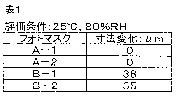
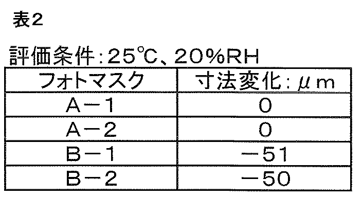

表1~3から明らかなように、基材14が張力のかかった状態でフレーム12に固定されたフォトマスク(A-1,A-2)は湿度変化に伴う寸法変化がなく、温度変化に伴う寸法変化もフレーム12のないフォトマスク(B-1,B-2)に比べて著しく小さいことが確認できた。
すなわち、本発明の製造方法で得られた実施例1および実施例2のフォトマスク(A-1,A-2)は、近年のパターンの細線化や要求精度の厳格化の要求に対して、ガラスから成る基材14を用いたフォトマスクと同様に、使用もしくは保管される雰囲気を特別に調整しなくても対応可能であることを示している。
なお、温度変化に伴うフォトマスクの寸法変化は、フレーム12の素材である42アロイの熱線膨張率とほぼ一致しており、このことは、寸法変化を更に低減するためにはより熱線膨張率の小さい素材をフレームに用いればよいことを示唆している。
10・・・フォトマスク
10a・・フォトマスク
10b・・フォトマスク
12・・・フレーム
14・・・基材
16・・・遮光層
18・・・レーザー
20・・・パターン
20a・・パターン
20b・・パターン
22・・・評点
L・・・評点間距離
10a・・フォトマスク
10b・・フォトマスク
12・・・フレーム
14・・・基材
16・・・遮光層
18・・・レーザー
20・・・パターン
20a・・パターン
20b・・パターン
22・・・評点
L・・・評点間距離
Claims (4)
- 高分子化合物を主成分とするフィルムまたはシートからなる基材と、
前記基材の少なくとも一方の面に配設された遮光層と、
前記基材の少なくとも一方の面に配設されたフレームと、
から少なくとも構成されたフォトマスクであって、
前記フォトマスクは、
使用および保管される雰囲気において、
前記基材が、前記フレームに張力のかかった状態で固定されていることを特徴とするフォトマスク。 - 前記フレームが、熱線膨張率35ppm/℃以下の素材からなることを特徴とする請求項1に記載のフォトマスク。
- 前記基材は、熱線膨張率が湿度線膨張率より大きいことを特徴とする請求項1または2に記載のフォトマスク。
- 前記基材が、環状オレフィン系樹脂を主成分とすることを特徴とする請求項1から3のいずれかに記載のフォトマスク。
Applications Claiming Priority (4)
| Application Number | Priority Date | Filing Date | Title |
|---|---|---|---|
| JP2008-263430 | 2008-10-10 | ||
| JP2008263430 | 2008-10-10 | ||
| JP2008304196A JP2010113315A (ja) | 2008-10-10 | 2008-11-28 | フォトマスク |
| JP2008-304196 | 2008-11-28 |
Publications (1)
| Publication Number | Publication Date |
|---|---|
| WO2010041508A1 true WO2010041508A1 (ja) | 2010-04-15 |
Family
ID=42100464
Family Applications (1)
| Application Number | Title | Priority Date | Filing Date |
|---|---|---|---|
| PCT/JP2009/063672 Ceased WO2010041508A1 (ja) | 2008-10-10 | 2009-07-31 | フォトマスク |
Country Status (3)
| Country | Link |
|---|---|
| JP (1) | JP2010113315A (ja) |
| TW (1) | TW201015210A (ja) |
| WO (1) | WO2010041508A1 (ja) |
Cited By (3)
| Publication number | Priority date | Publication date | Assignee | Title |
|---|---|---|---|---|
| US9658526B2 (en) | 2015-06-30 | 2017-05-23 | Taiwan Semiconductor Manufacturing Company, Ltd. | Mask pellicle indicator for haze prevention |
| US10012899B2 (en) | 2016-09-01 | 2018-07-03 | Taiwan Semiconductor Manufacturing Co., Ltd. | Graphene pellicle for extreme ultraviolet lithography |
| US10162258B2 (en) | 2016-12-15 | 2018-12-25 | Taiwan Semiconductor Manufacturing Co., Ltd. | Pellicle fabrication methods and structures thereof |
Families Citing this family (1)
| Publication number | Priority date | Publication date | Assignee | Title |
|---|---|---|---|---|
| WO2021199402A1 (ja) * | 2020-04-02 | 2021-10-07 | コニカミノルタ株式会社 | 積層フィルム、偏光板、表示装置及び偏光板ロールの製造方法 |
Citations (7)
| Publication number | Priority date | Publication date | Assignee | Title |
|---|---|---|---|---|
| JPS56120129A (en) * | 1979-12-27 | 1981-09-21 | Sacher Rudolf Gmbh | Mask without support and method of manufacturing same |
| JPS62118350A (ja) * | 1985-11-13 | 1987-05-29 | イ−エムエス・イオ−ネン・ミクロフアブリカチオンス・ジステ−メ・ゲゼルシヤフト・ミト・ベシユレンクテル・ハウツング | 粒子線又は輻射線で照射し得るマスクとその作製方法 |
| JPH0294425A (ja) * | 1988-09-30 | 1990-04-05 | Canon Inc | X線マスク構造体 |
| JPH11111614A (ja) * | 1997-07-24 | 1999-04-23 | Oputonikusu Seimitsu:Kk | X線マスクおよびこの製造方法およびこれを用いて製作したマイクロ部品 |
| JP2002072451A (ja) * | 2000-08-31 | 2002-03-12 | Kimoto & Co Ltd | フォトマスク |
| JP2002169269A (ja) * | 2000-11-30 | 2002-06-14 | Kimoto & Co Ltd | フォトマスクの作製方法およびフォトマスク |
| WO2002088216A1 (fr) * | 2001-04-27 | 2002-11-07 | Mitsui Chemicals, Inc. | Polymeres cycloolefiniques fluores, procedes de preparation de monomeres cycloolefiniques fluores et polymeres associes, et leur application |
-
2008
- 2008-11-28 JP JP2008304196A patent/JP2010113315A/ja active Pending
-
2009
- 2009-07-31 WO PCT/JP2009/063672 patent/WO2010041508A1/ja not_active Ceased
- 2009-09-29 TW TW098132955A patent/TW201015210A/zh unknown
Patent Citations (7)
| Publication number | Priority date | Publication date | Assignee | Title |
|---|---|---|---|---|
| JPS56120129A (en) * | 1979-12-27 | 1981-09-21 | Sacher Rudolf Gmbh | Mask without support and method of manufacturing same |
| JPS62118350A (ja) * | 1985-11-13 | 1987-05-29 | イ−エムエス・イオ−ネン・ミクロフアブリカチオンス・ジステ−メ・ゲゼルシヤフト・ミト・ベシユレンクテル・ハウツング | 粒子線又は輻射線で照射し得るマスクとその作製方法 |
| JPH0294425A (ja) * | 1988-09-30 | 1990-04-05 | Canon Inc | X線マスク構造体 |
| JPH11111614A (ja) * | 1997-07-24 | 1999-04-23 | Oputonikusu Seimitsu:Kk | X線マスクおよびこの製造方法およびこれを用いて製作したマイクロ部品 |
| JP2002072451A (ja) * | 2000-08-31 | 2002-03-12 | Kimoto & Co Ltd | フォトマスク |
| JP2002169269A (ja) * | 2000-11-30 | 2002-06-14 | Kimoto & Co Ltd | フォトマスクの作製方法およびフォトマスク |
| WO2002088216A1 (fr) * | 2001-04-27 | 2002-11-07 | Mitsui Chemicals, Inc. | Polymeres cycloolefiniques fluores, procedes de preparation de monomeres cycloolefiniques fluores et polymeres associes, et leur application |
Cited By (3)
| Publication number | Priority date | Publication date | Assignee | Title |
|---|---|---|---|---|
| US9658526B2 (en) | 2015-06-30 | 2017-05-23 | Taiwan Semiconductor Manufacturing Company, Ltd. | Mask pellicle indicator for haze prevention |
| US10012899B2 (en) | 2016-09-01 | 2018-07-03 | Taiwan Semiconductor Manufacturing Co., Ltd. | Graphene pellicle for extreme ultraviolet lithography |
| US10162258B2 (en) | 2016-12-15 | 2018-12-25 | Taiwan Semiconductor Manufacturing Co., Ltd. | Pellicle fabrication methods and structures thereof |
Also Published As
| Publication number | Publication date |
|---|---|
| TW201015210A (en) | 2010-04-16 |
| JP2010113315A (ja) | 2010-05-20 |
Similar Documents
| Publication | Publication Date | Title |
|---|---|---|
| KR102180655B1 (ko) | 터치 패널용 흑색 감광성 조성물 및 터치 패널 | |
| CN108475143B (zh) | 薄膜触控传感器及其制作方法 | |
| WO2011065032A1 (ja) | 透明導電性積層体およびその製造方法ならびに静電容量式タッチパネル | |
| KR20060115735A (ko) | 적층 필름 | |
| KR20220118536A (ko) | 광학 적층체 | |
| WO2010041508A1 (ja) | フォトマスク | |
| CN112703436A (zh) | 偏光膜以及包含其的偏光板及显示装置 | |
| US20160070029A1 (en) | Photosensitive epoxy resin composition for optical waveguide, curable film for formation of optical waveguide, and optical waveguide and optical/electrical transmission hybrid flexible printed wiring board produced by using the photosensitive epoxy resin composition, and optical waveguide production method | |
| TW202016168A (zh) | 光波導形成用感光性環氧樹脂組成物、光波導形成用感光性薄膜及使用其之光波導、光電傳輸用混合撓性印刷配線板 | |
| US20230006182A1 (en) | Display panel, display device, and method for manufacturing display panel | |
| WO2014141921A1 (ja) | タッチパネル用積層体およびタッチパネル用積層体の製造方法 | |
| KR200490675Y1 (ko) | 감광성 드라이필름 | |
| CN116547320B (zh) | 光敏元件、干膜光致抗蚀剂、抗蚀剂图案、电路板和使用其的显示装置 | |
| WO2016133074A1 (ja) | ポリマー光導波路複合体 | |
| US20220206632A1 (en) | Touch panel, laminate having the same, and manufacturing method thereof | |
| JP6794646B2 (ja) | 感光性樹脂組成物、該組成物で製造された絶縁フィルム、及び該絶縁フィルムを備えたプリント回路基板 | |
| TW201825545A (zh) | 光波導形成用感光性環氧樹脂組成物、光波導形成用硬化性薄膜及使用其之光波導、光電傳輸用混合撓性印刷配線板 | |
| JP6338402B2 (ja) | 樹脂フィルム | |
| KR20200098641A (ko) | 터치 센서 패널용 투명 필름 기재 및 그것을 이용한 터치 센서 패널 | |
| TWI721586B (zh) | 偏光板及包含其的光學顯示器 | |
| JP7517341B2 (ja) | 積層体の製造方法 | |
| KR100769369B1 (ko) | 반도체 및 디스플레이 패널용 포토마스크 | |
| KR102564938B1 (ko) | 신축성 기판 및 이를 포함하는 전자 장치 | |
| TW202043045A (zh) | 偏光件保護用積層體及使用該積層體之偏光板 | |
| JP2871757B2 (ja) | ペリクル |
Legal Events
| Date | Code | Title | Description |
|---|---|---|---|
| 121 | Ep: the epo has been informed by wipo that ep was designated in this application |
Ref document number: 09819044 Country of ref document: EP Kind code of ref document: A1 |
|
| NENP | Non-entry into the national phase |
Ref country code: DE |
|
| 122 | Ep: pct application non-entry in european phase |
Ref document number: 09819044 Country of ref document: EP Kind code of ref document: A1 |