WO2010035334A1 - 情報記録再生装置及び方法 - Google Patents
情報記録再生装置及び方法 Download PDFInfo
- Publication number
- WO2010035334A1 WO2010035334A1 PCT/JP2008/067504 JP2008067504W WO2010035334A1 WO 2010035334 A1 WO2010035334 A1 WO 2010035334A1 JP 2008067504 W JP2008067504 W JP 2008067504W WO 2010035334 A1 WO2010035334 A1 WO 2010035334A1
- Authority
- WO
- WIPO (PCT)
- Prior art keywords
- signal
- value
- information recording
- correction
- signal level
- Prior art date
- Legal status (The legal status is an assumption and is not a legal conclusion. Google has not performed a legal analysis and makes no representation as to the accuracy of the status listed.)
- Ceased
Links
Images


Classifications
-
- G—PHYSICS
- G11—INFORMATION STORAGE
- G11B—INFORMATION STORAGE BASED ON RELATIVE MOVEMENT BETWEEN RECORD CARRIER AND TRANSDUCER
- G11B7/00—Recording or reproducing by optical means, e.g. recording using a thermal beam of optical radiation by modifying optical properties or the physical structure, reproducing using an optical beam at lower power by sensing optical properties; Record carriers therefor
- G11B7/08—Disposition or mounting of heads or light sources relatively to record carriers
- G11B7/09—Disposition or mounting of heads or light sources relatively to record carriers with provision for moving the light beam or focus plane for the purpose of maintaining alignment of the light beam relative to the record carrier during transducing operation, e.g. to compensate for surface irregularities of the latter or for track following
- G11B7/095—Disposition or mounting of heads or light sources relatively to record carriers with provision for moving the light beam or focus plane for the purpose of maintaining alignment of the light beam relative to the record carrier during transducing operation, e.g. to compensate for surface irregularities of the latter or for track following specially adapted for discs, e.g. for compensation of eccentricity or wobble
- G11B7/0956—Disposition or mounting of heads or light sources relatively to record carriers with provision for moving the light beam or focus plane for the purpose of maintaining alignment of the light beam relative to the record carrier during transducing operation, e.g. to compensate for surface irregularities of the latter or for track following specially adapted for discs, e.g. for compensation of eccentricity or wobble to compensate for tilt, skew, warp or inclination of the disc, i.e. maintain the optical axis at right angles to the disc
Definitions
- the present invention relates to the technical field of an information recording / reproducing apparatus and method including, for example, a tilt correcting means of an optical pickup.
- an optical pickup for irradiating the optical disc with a recording / reproducing laser beam and receiving the reflected light is provided. It has been. Data is recorded by the laser light emitted from such an optical pickup, and on the other hand, the data recorded on the optical disk is read based on the reflected light of the received laser light.
- the angle between the optical disk and the optical pickup varies due to factors such as tilt and warp of the optical disk, and the irradiated laser beam is tilted with respect to the optical disk surface, so that suitable irradiation cannot be performed.
- a technical problem has been pointed out that when the tilt of such laser light, called so-called radial tilt, is large, the quality of the reproduction signal such as an increase in read signal error is caused by factors such as an increase in jitter. .
- Patent Document 2 discloses a tilt that minimizes the number of errors in an RF signal by performing coarse adjustment for obtaining a tilt amount that maximizes the amplitude of the RF signal and fine adjustment that swings the tilt amount within a predetermined range.
- a tilt correction mechanism for determining the amount is disclosed.
- the amplitude of the RF signal varies based on the output of the laser power and the reflectance variation of the optical disk surface, and the variation in the amplitude of the RF signal and the variation in the amplitude of the RF signal due to the radial tilt. May not be determined.
- the influence on the laser power due to such power supply capacity and voltage fluctuations has been conventionally suppressed to some extent by the hardware configuration including, for example, a regulator.
- the hardware configuration for suppressing such an influence has technical problems such as a complicated configuration due to an increase in the number of component parts of the apparatus and an increase in cost.
- the present invention has been made in view of, for example, the above-described conventional problems, and is not affected by, for example, fluctuations in laser power caused by fluctuations in power supply voltage or the like, without further comprising a configuration such as a regulator. It is an object of the present invention to provide an information recording / reproducing apparatus and method capable of applying an appropriate tilt correction amount.
- an information recording / reproducing apparatus of the present invention irradiates a laser beam on the information recording medium and performs reflection of the laser light in order to perform at least one of recording and reproducing information on the information recording medium.
- An information recording / reproducing apparatus including an optical pickup for receiving light, wherein the signal detection means detects an RF signal based on the reflected light, the maximum value of the signal level of the RF signal, and the minimum value of the signal level of the RF signal
- Correction value calculating means for calculating a correction reference value by dividing the difference between the correction reference value and a tilt correction means for performing tilt correction of the optical pickup based on a tilt correction value that maximizes the correction reference value With.
- an information recording / reproducing method of the present invention irradiates a laser beam on the information recording medium and performs reflection of the laser light in order to perform at least one of recording and reproducing information on the information recording medium.
- An information recording / reproducing method in an information recording / reproducing apparatus including an optical pickup for receiving light, wherein a signal detecting step of detecting an RF signal based on the reflected light, a maximum value of a signal level of the RF signal, and the RF signal
- a correction value calculation step for calculating a correction reference value by dividing a difference from the minimum value of the signal level by a predetermined value, and a tilt correction value of the optical pickup based on a tilt correction value that maximizes the correction reference value
- a tilt correction step for performing for performing.
- the information recording medium is irradiated with a laser beam and the reflected light of the laser beam is received in order to perform at least one of recording and reproducing information with respect to the information recording medium.
- An information recording / reproducing apparatus including an optical pickup, wherein a signal detection unit that detects an RF signal based on the reflected light, and a difference between a maximum value of the signal level of the RF signal and a minimum value of the signal level of the RF signal
- a correction value calculating unit that calculates a correction reference value by dividing by a predetermined value; and a tilt correction unit that performs tilt correction of the optical pickup based on a tilt correction value that maximizes the correction reference value.
- the difference between the maximum value and the minimum value of the signal level of the RF signal is determined based on the RF signal generated from the reflected light received by the optical pickup.
- a value divided by the value (in other words, normalized) is calculated as the correction reference value.
- a tilt correction amount is calculated so that the correction reference value is maximized, and tilt correction to the optical pickup is performed based on the calculated tilt correction amount.
- the optical pickup typically irradiates the recording layer of an information recording medium such as an optical disc, and the reflected light is received by the optical pickup. Then, an RF signal is generated from the received reflected light by the signal detection means.
- a correction reference value for tilt correction which will be described in detail later, is calculated by the correction value calculation means.
- the tilt correction unit performs tilt correction using a tilt correction amount that maximizes the correction reference value calculated by the correction ground calculation unit.
- the tilt correction amount for tilt correction corresponding to the radial tilt is calculated based on only the amplitude of the RF signal (or only the amplitude and error value of the RF signal).
- the signal level of an RF signal used for recording / reproducing data varies depending on the radial tilt amount and the laser power.
- variations in the RF signal level due to the radial tilt amount differ from the variations in the signal level of the RF signal due to the laser power variation.
- the signal level variation of the RF signal based on the laser power variation tends to vary the minimum value of the signal level so as to follow the variation of the maximum value of the signal level. . That is, if the maximum value of the signal level increases as the laser power varies, the minimum value of the signal level also increases, and if the maximum value of the signal level decreases, the minimum value of the signal level also decreases. .
- the average value of the signal level of the RF signal (typically, the average value of the maximum value and the minimum value of the RF signal) also tends to undergo the same variation.
- the fluctuation of the maximum value of the signal level accompanying the fluctuation of the radial tilt amount and the fluctuation of the minimum value of the signal level tend to be symmetrical.
- the maximum value of the signal level increases as the radial tilt amount fluctuates, the minimum value of the signal level similarly decreases, and when the maximum value of the signal level decreases, the minimum value of the signal level increases.
- the maximum value of the signal level and the minimum value of the signal level have such symmetrical fluctuations, it is observed that the average value of the signal level is hardly or not affected by the fluctuation of the radial tilt amount.
- the difference between the maximum value and the minimum value of the signal level of the RF signal that is, (maximum value of signal level ⁇ minimum value of signal level) is divided by a predetermined value.
- the maximum value and the minimum value of the signal level of the RF signal are determined from the signal level value of the RF signal and the signal level of the RF signal when the laser beam is not irradiated (that is, the background of the signal level).
- the signal level is such that the potential difference becomes maximum and minimum.
- the average value of the signal level of the RF signal also indicates the average value of each signal level represented by the potential difference from the background signal level. That is, in the present embodiment, the signal level of the RF signal typically represents the signal level of the RF signal obtained by removing the background signal level of the RF signal due to an electrical offset or the like.
- the signal level of the RF signal indicates the signal level of the RF signal from which the background of the RF signal is removed.
- the “predetermined value” is intended to indicate a predetermined numerical value, a function, or the like that is set so that the above-described variation of the signal level of the RF signal can be suitably determined.
- it is a numerical value determined based on the RF signal, for example, an average value of the signal level of the RF signal.
- the predetermined value used May be anything else.
- the difference between the maximum value and the minimum value of the signal level of the RF signal is divided by a predetermined value (in other words, normalized), that is, (maximum value of RF signal ⁇ minimum value of RF signal) / predetermined
- the correction reference value for determining the tilt correction amount is calculated by the calculation method represented by the value.
- an appropriate tilt correction amount based on the correction reference value is calculated by the tilt correction means, and tilt correction based on the tilt correction amount is performed.
- the correction reference value determined based on the RF signal that varies based on the tilt correction amount (that is, varies in the same tendency as the variation based on the variation of the radial tilt amount) and the predetermined value described above.
- the tilt correction amount is determined so that becomes the maximum. Specifically, for example, prior to actual recording and playback operations, the tilt correction amount that maximizes the correction reference value is obtained by the tilt correction means changing the tilt correction amount while checking the value of the correction reference value. Is determined. Alternatively, a tilt correction amount calculated in advance by such an operation is stored in a data storage unit such as a memory typically provided in the information recording / reproducing apparatus, and the tilt correction amount can be calculated by reading such data. It may be decided.
- the difference between the maximum value and the minimum value of the signal level of the RF signal generated from the received reflected light is divided by a predetermined value (in other words, The normalized value is used as a correction reference value, and the tilt correction amount is calculated so that the correction reference value is maximized, so that a suitable tilt correction can be performed without being affected by fluctuations in laser power or the like. I can do it.
- the predetermined value is a value based on the RF signal.
- the predetermined value related to the calculation of the correction reference value described above is determined or calculated based on the RF signal. That is, the correction reference value is calculated by dividing (in other words, normalizing) the difference between the maximum value and the minimum value of the signal level of the RF signal by a predetermined value determined based on the RF signal.
- the predetermined value is a value based on the RF signal as described above
- the predetermined value may be an average value of the signal level of the RF signal.
- the predetermined value relating to the calculation of the correction reference value described above is an average value of the signal level of the RF signal.
- the difference between the maximum value and the minimum value of the signal level of the RF signal is divided by the average value of the signal level of the RF signal (in other words, normalized), thereby calculating the correction reference value.
- the average value of the signal level of the RF signal is typically the average value of the maximum value and the minimum value of the signal level of the RF signal. Therefore, the maximum value and the minimum value of the signal level of the RF signal are If detected, the correction reference value can be calculated without requiring a further special configuration. It goes without saying that the average value of the signal level of the RF signal may be calculated by other methods.
- the predetermined value is a value based on the RF signal as described above
- the predetermined value may be the maximum value of the signal level of the RF signal.
- the predetermined value relating to the calculation of the correction reference value described above is the maximum value of the signal level of the RF signal.
- the difference between the maximum value and the minimum value of the signal level of the RF signal is divided by the maximum value of the signal level of the RF signal (in other words, normalized), thereby calculating the correction reference value. Done. Therefore, if the maximum value and the minimum value of the signal level of the RF signal are detected, the correction reference value can be calculated without any further special configuration.
- the predetermined value is a value based on the RF signal as described above
- the predetermined value may be a minimum value of the signal level of the RF signal.
- the predetermined value relating to the calculation of the correction reference value described above is the minimum value of the signal level of the RF signal.
- the difference between the maximum value and the minimum value of the signal level of the RF signal is divided by the minimum value of the signal level of the RF signal (in other words, normalized), thereby calculating the correction reference value. Done. Therefore, if the maximum value and the minimum value of the signal level of the RF signal are detected, the correction reference value can be calculated without any further special configuration.
- the predetermined value is a value based on the RF signal as described above
- the predetermined value may be the total amount of the reflected light.
- the total amount of the reflected light is typically calculated by integrating an RF signal generated by an electrical signal converted from the reflected light received by the photodetector.
- the total amount of reflected light tends to fluctuate in numerical values similar to the average value of the signal level of the RF signal based on the tilt correction, the same as the average value of the signal level of the RF signal. It is possible to calculate a correction reference value having a tendency.
- the tilt correction unit performs the tilt correction based on the tilt correction value by setting an angle of the optical pickup with respect to the information recording medium. Do.
- the tilt correction means is configured to include a three-axis actuator configured to change the relative angle of the optical pickup with respect to an information recording medium such as an optical disk, for example.
- the tilt correction means configured as described above performs tilt correction by changing the optical path of the laser light and the reflected light by changing the position and angle of the optical pickup based on the tilt correction value described above.
- the tilt correction means includes a liquid crystal element disposed in an optical path between the optical pickup and the information recording medium. By setting a refractive index distribution, the tilt correction is performed based on the tilt correction value.
- the tilt correction means is configured to include a liquid crystal element or the like in the optical path of the laser light irradiated and received by the optical pickup.
- the tilt correction means configured as described above performs tilt correction by changing the refractive index distribution of the liquid crystal element based on the above-described tilt correction value, thereby changing the optical paths of the laser light and the reflected light.
- the information recording medium is irradiated with laser light and reflected light of the laser light is received in order to perform at least one of recording and reproduction of information on the information recording medium.
- An information recording / reproducing method in an information recording / reproducing apparatus including an optical pickup, wherein a signal detecting step of detecting an RF signal based on the reflected light, a maximum value of a signal level of the RF signal, and a minimum of a signal level of the RF signal
- a correction value calculating step for calculating a correction reference value by dividing a difference from the value by a predetermined value, and a tilt correction for performing a tilt correction of the optical pickup based on a tilt correction value that maximizes the correction reference value A process.
- the embodiment of the information recording / reproducing method of the present invention it is possible to obtain an information recording / reproducing method that can preferably enjoy various effects according to the above-described embodiment of the information recording / reproducing apparatus of the present invention.
- the embodiment of the information recording / reproducing method of the present invention can also adopt various aspects.
- the information recording / reproducing apparatus of the present invention it is provided with a signal detection means, a correction value calculation means, and a tilt correction means. Moreover, according to the information recording / reproducing method of the present invention, the method includes a signal detection step, a correction value calculation step, and a tilt correction step. Therefore, it is possible to obtain an appropriate tilt correction amount that is not affected by fluctuations that occur in the power supply voltage.
- FIG. 1 is a schematic block diagram conceptually showing the configuration of the information recording / reproducing apparatus 1.
- the information recording / reproducing apparatus 1 has a function of recording data on the optical disc 100 and a function of reproducing data recorded on the optical disc 100.
- an information recording / reproducing apparatus 1 includes a disk drive 10 on which an optical disk 100 is actually loaded and data is recorded and reproduced, a personal computer that controls data recording and reproduction, and the like.
- the recording / reproducing control unit 21 is provided.
- the disk drive 10 includes a spindle motor 11, an optical pickup 12, a signal processing unit 13, a peak detection unit 14, a bottom detection unit 15, an A / D converter 16, an equalizer 17, a microcomputer 18, a D / A converter 19 and a driver IC 20. It is configured with.
- the recording / playback control unit 21 includes an operation button (not shown), a display panel, a CPU, a memory, a bus that connects each unit, and the like.
- the spindle motor 11 rotates and stops the optical disc 100, and operates when accessing the optical disc 100. More specifically, the spindle motor 11 is configured to rotate and stop the optical disc 100 at a predetermined speed while receiving spindle servo from a servo unit (not shown) or the like.
- the optical pickup 12 is, for example, a laser diode LD that irradiates the laser beam LB in a manner that can change the laser power, which is not shown, and receives the reflected light for electrical use.
- a photo detector PD for converting into a signal, a collimator lens, an objective lens, and the like are provided.
- the optical pickup 12 is driven by an actuator 121, and is configured to perform focus control, tracking control, and the like based on a focus control signal, a tracking control signal, and the like from a microcomputer 18 described later.
- the optical pickup 21 is configured to be able to perform tilt correction based on a tilt correction signal from a microcomputer, which will be described later, by the correction element 122.
- a correction element 122 may be, for example, a three-axis actuator configured to be able to drive the optical pickup 12.
- the optical pickup 12 with respect to the optical disk 100 is used. Tilt correction is performed by adjusting the relative angle and the like.
- the correction element 122 may be a liquid crystal element provided in the optical path of the laser beam LB and the reflected light between the optical pickup 12 and the optical disc 100.
- the correction element 122 is based on a tilt correction signal from the microcomputer 18.
- the optical path of the laser beam LB and the reflected light is suitably corrected by changing the refractive index distribution in the liquid crystal element.
- the signal processing unit 13 processes the output signal of the photodetector PD provided in the optical pickup 12 (that is, a signal indicating the reflected light of the laser beam LB and is a read signal), and performs RF signal, focus error signal, and tracking. It is configured to generate an error signal or the like.
- the focus error signal and the tracking error signal are input to the A / D (AC / DC) converter 16A and passed through the equalizer 17, the D / A (DC / AC) converter 19 and the driver IC 20 to be focused.
- the control signal and the tracking control signal are input to the actuator 121 and used for focus control and tracking control of the optical pickup 12.
- the RF signal is input to the peak detection unit 14 and the bottom detection unit 15, and the maximum value RFtop and the minimum value RFbottom of the signal level of the RF signal are detected.
- the difference between the signal level based on the signal level 0, the maximum value, and RFoff is RFtop, and the difference between the actual minimum signal level and RFoff is RFbottom.
- the signal level of the RF signal indicates the signal level of the RF signal based on the RFoff value.
- RF signals are input to the microcomputer 18 via the A / D converters 16B and 16C, respectively.
- the microcomputer 18 is connected to each part of the disk drive 10 and controls the entire disk drive 10 by performing control related to recording and reproduction.
- software or firmware for operating the microcomputer 18 is stored in a memory (not shown) provided in the microcomputer 18.
- the microcomputer 18 receives an input of an RF signal (that is, RF signal data including RFtop and RFbottom data) and the like, and the like, a tilt correction amount for the correction element 122 to perform a suitable tilt correction.
- a tilt correction signal for instructing is generated.
- the microcomputer 18 processes the input RF signal, for example, the RF average of the RF signal that is an average value of the signal level of the RF signal (typically, the average value of the maximum value and the minimum value of the RF signal).
- the RFoff may be calculated as the signal level of the RF signal when the calculation or the laser beam LB is not irradiated.
- amendment which makes the signal level of RF signal the value on the basis of RFoff value can be performed suitably.
- the tilt correction amount which will be described in detail later, is calculated using various parameters acquired by the operation of the microcomputer 18.
- the data used for the recording operation and the reproducing operation according to the recording / reproducing apparatus of this embodiment is mainly exchanged between the microcomputer 18 of the disk drive 10 and the recording / reproducing control unit 21.
- the recording / reproducing control unit 21 transmits an operation control command of the disk drive 10 based on an operation instruction such as recording or reproduction to the microcomputer 18 to control the entire disk drive 10. Also, recording data is transmitted to and received from the disk drive 10 and data to be reproduced is received, and a recording or reproducing operation is performed.
- a specific example of the disk drive information recording / reproducing apparatus 1 described above is a household device such as a player device that reproduces video.
- This player device is a device that outputs a video signal reproduced from a disc to an external display device such as a television.
- the disk drive 10 is a disk drive that records or reproduces data under the control of a recording / reproduction control unit 21 such as a personal computer or a workstation. Host computer 20.
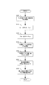
- FIG. 2 is a flowchart conceptually showing a flow of such a basic operation of the information recording / reproducing apparatus 1 according to this embodiment.
- the RF signal level RFoff is detected when the laser diode LD of the optical pickup 12 is in an off state (that is, a state in which the laser beam LB is not irradiated) (step: S100). That is, a read signal generated from light received by the photodetector PD of the optical pickup in a state where the laser diode LD is not driven is input to the signal processing unit 13 and an RF signal is generated.
- the RFoff value is detected by detecting the signal level of the RF signal by the peak detector 14 and the bottom detector 15. In the subsequent processing, the signal level of the RF signal is detected based on this RFoff value.
- the laser diode LD is driven (step: S110), and focus control by the actuator 121 is performed based on the focus signal generated from the reflected light received by the photodetector PD (step: S120).
- step S130 and S140 detection of the maximum value RFtop and the minimum value RFbottom of the signal level of the RF signal is performed (steps S130 and S140). Specifically, the reflected light of the received laser beam LB is converted into an electrical signal by the photodetector PD of the optical pickup 12 and output to the signal processing unit 13. Then, in the signal processing unit 13, an RF signal is generated from the electrical signal, and subsequently, each of RFtop and RFbottom is detected from the RF signal by the peak detection unit 14 and the bottom detection unit 15. The detected RF signal is input to the microcomputer 18 via the A / D converters 16B and 16C.
- a correction reference value is calculated by the microcomputer 18 (step: S150).
- the correction reference value is calculated by dividing the difference between the maximum value and the minimum value of the signal level of the RF signal (that is, RFtop ⁇ RFbottom) by a predetermined value K.
- the predetermined value K is an average value of the signal level of the RF signal (that is, RF average). Therefore, in the basic operation example of the present embodiment, the correction reference value is calculated as (RFtop ⁇ RFbottom) / RFaverage.
- a tilt correction amount that maximizes the correction reference value (that is, the modulation factor) is determined (step: S160).
- the degree of modulation within the range is achieved.
- the tilt correction amount that maximizes is determined.
- tilt correction based on the tilt correction amount determined as described above is performed by the correction element 122 under the control of the microcomputer 18.
- FIG. 3 is an example of a graph conceptually showing the fluctuation of the RF signal when the RFoff value is the origin.
- FIG. 3A shows the fluctuation of the RF signal due to the fluctuation of the radial tilt amount.
- FIG. 3B illustrates an example of the variation of the RF signal caused by the variation of the laser power.
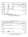
- FIG. 4 is a graph showing various numerical values such as a maximum value RFtop, a minimum value RFbottom, an average value RFaverage, and a correction reference value (RFtop ⁇ RFbottom) / RFaverage of an RF signal.
- FIG. 3 is an example of a graph conceptually showing the fluctuation of the RF signal when the RFoff value is the origin.
- FIG. 3A shows the fluctuation of the RF signal due to the fluctuation of the radial tilt amount.
- FIG. 3B illustrates an example of the variation of the RF signal caused by the variation of the laser power.
- FIG. 4 is a graph showing various numerical values such as a maximum
- FIG. 4A is a graph showing fluctuations of various numerical values when the tilt correction amount is determined using RF average.
- FIG. 4B is a graph showing fluctuations of various numerical values when a ripple is applied to the power supply voltage.
- the graph of FIG. 4A shows various numerical value fluctuations of the RF signal based on the radial tilt fluctuation
- the graph of FIG. 4B shows the RF signal based on the laser power fluctuation. The fluctuations of various values are shown.
- the signal level variation mode of the RF signal based on the variation of the laser power is such that the minimum value RFbottom of the signal level follows the variation of the maximum value RFtop of the signal level. It is also observed that there is a tendency to fluctuate. That is, when RFtop increases with fluctuations in laser power, RFbottom also increases, and when RFtop decreases, RFbottom also decreases. Since RFtop and RFbottom increase / decrease in this way, the tendency that RF average also increases / decreases similarly is observed.
- the tilt correction is performed using the RF average, the influence of the fluctuation of the laser power is preferably eliminated. It can be seen that the correction amount can be determined.
- the operation of determining the tilt correction amount suitably while eliminating the influence of the fluctuation of the laser power will be further described with reference to FIG.
- FIG. 4A various numerical values of the RF signal when the radial tilt fluctuates in the section shown as “tilt fluctuation section” are shown.
- FIG. 4 (a) As a feature, when RFtop decreases as the radial tilt changes, RFbottom increases. On the other hand, when RFtop increases as the radial tilt changes, RFbottom increases. There is a decreasing correlation. Further, since the increase / decrease in RFtop and the decrease / increase in RFbottom are in a corresponding quantitative relationship, the value of RF average remains almost constant without being affected by the variation in radial tilt.
- the correction reference value (RFtop ⁇ RFbottom) / RFaverage tends to increase when RFtop increases. That is, the correction reference value (RFtop ⁇ RFbottom) / RFaverage tends to fluctuate greatly as the radial tilt varies.
- the correction reference value (RFtop-RFbottom) / RFaverage is maximized by changing the tilt correction amount while observing the correction reference value (RFtop-RFbottom) / RFaverage.
- the amount of tilt correction can be determined.
- the RF signal when ripple is applied to the power supply voltage that is, when the laser power is periodically changed in the section indicated as “ripple applied voltage fluctuation section”. Variations in various values of are shown. According to FIG. 4B, as a feature, there is a correlation that when the RFtop increases due to the fluctuation of the laser power, the RFbottom also increases. Similarly, when RFtop decreases due to fluctuations in laser power, there is a correlation that RFbottom also decreases. Therefore, the RF average is also periodically changed as the laser power changes.
- the fluctuation amplitude of the correction reference value is It tends to be smaller than the difference (RFtop-RFbottom) between the maximum value and the minimum value of the RF signal level. For this reason, the fluctuation amount of the correction reference value (RFtop-RFbottom) / RFaverage accompanying the fluctuation of the laser power is almost ignored compared with the fluctuation amount of the correction reference value (RFtop-RFbottom) / RFaverage accompanying the fluctuation of the radial tilt. It tends to fluctuate only as much as possible.
- the correction reference value is not limited to the above-described numerical values, and other numerical values that can be expected to have a calculation result similar to such numerical values may also be applied.
- the optical disc 100 is a Blu-ray Disc having the longest mark length 8T
- the maximum signal level of the RF signal obtained by reading the 8T mark is I8H
- the minimum signal level of the RF signal obtained by reading the 8T mark The degree of modulation (I8H-I8L) / I8H when is set to I8L can also be applied as the correction reference value.
- the present invention is not limited to the above-described embodiments, and can be appropriately changed without departing from the gist or concept of the invention that can be read from the claims and the entire specification, and information recording / reproduction with such changes is possible.
- the apparatus and the information recording / reproducing method are also included in the technical scope of the present invention.
Landscapes
- Optical Recording Or Reproduction (AREA)
Abstract
本発明の情報記録再生装置1は、情報記録媒体100に対する情報の記録及び再生の少なくとも一方を行うために情報記録媒体100にレーザ光LBを照射し、且つ該レーザ光LBの反射光を受光する光ピックアップ12を備える情報記録再生装置1であって、反射光に基づくRF信号を検出する信号検出手段13と、RF信号の信号レベルの最大値とRF信号の信号レベルの最小値との差分を所定の値で除算することで補正基準値を算出する補正値算出手段18と、補正基準値が最大となるチルト補正値に基づいて、光ピックアップのチルト補正を行うチルト補正手段121とを備える。
Description
本発明は、例えば光ピックアップのチルト補正手段を備える情報記録再生装置及び方法の技術分野に関する。
CDやDVDやBlu-ray Disc等の光ディスクにデータの記録や再生を行う記録再生装置においては、光ディスクに対して、記録再生用のレーザ光を照射し、その反射光を受光する光ピックアップが設けられている。このような光ピックアップが照射したレーザ光によりデータの記録が行われ、他方で、受光したレーザ光の反射光に基づいて、光ディスクに記録されているデータの読み取りが行われる。
ところが、例えば光ディスクの傾きや反りなどの要因によって、光ディスクと光ピックアップとの間の角度が変動し、照射されるレーザ光が光ディスク面に対して傾斜することから、好適な照射が行われない場合がある。いわゆるラジアルチルトと呼ばれるこのようなレーザ光の傾斜が大きい場合には、ジッタの増加等の要因により、読取信号のエラーの増加等の再生信号の品質劣化に繋がるという技術的問題が指摘されている。
このような技術的問題に対応して、例えば光ディスクに対する光ピックアップの相対的な角度を調整する、またはレーザ光の光路内に配置される素子によってレーザ光の照射角度を調整するなどの、いわゆるチルト補正機構を備える記録再生装置が開発されている。例えば、特許文献1では、好適なチルト補正を実施するために、データが記録されている光ディスクに対し、受光した光ディスクからの反射光に基づくRF(Radio Frequency)信号の振幅が最大となるようチルト補正量を求めるチルト補正方法が開示されている。また、特許文献2には、RF信号の振幅が最大となるチルト量を求める粗調整と、所定の範囲でチルト量を振る微調整とを行うことで、RF信号の誤り数が最小となるチルト量を求めるチルト補正機構が開示されている。
しかしながら、光ピックアップや光ディスクの状態などによっては、RF信号の振幅が最大となるようチルト補正量を求めたとしても、必ずしもラジアルチルトに起因するエラーが最小となるとは限らない場合がある。例えば、レーザパワーの出力や、光ディスク面の反射率の変動に基づいて、RF信号の振幅に変動が生じ、このようなRF信号の振幅の変動と、ラジアルチルトに起因するRF信号の振幅の変動とが判別できない可能性がある。特に、例えば光ピックアップ装置が接続される電源の容量や電圧の差異、またはノイズやリップルなどに起因してレーザパワーに差異が生じる可能性がある。従って、このような電源に変化が生じる状況では、上述した従来の構成によれば、レーザパワーに生じる変動からRF信号にも変動が生じるため、RF信号が最大となるチルト補正量の検索を行ったとしても、好適なチルト補正量の決定が行えないという技術的問題がある。
このような電源の容量や電圧の変動に起因するレーザパワーへの影響は、従来、例えばレギュレータなどを含むハードウェアの構成により、ある程度の抑制が行われてきた。しかしながら、このような影響を抑制するためのハードウェア構成には、装置の構成部品が増加することによる構成の複雑化や、高コスト化などの技術的な問題点があった。
本発明は、例えば上述した従来の問題点に鑑みなされたものであり、例えばレギュレータなどの構成を更に備えることなく、特に、電源電圧などの変動に起因するレーザパワーの変動などの影響を受けない適切なチルト補正量を適用することが出来る情報記録再生装置及び方法を提供することを課題とする。
上記課題を解決するために、本発明の情報記録再生装置は、情報記録媒体に対する情報の記録及び再生の少なくとも一方を行うために前記情報記録媒体にレーザ光を照射し、且つ該レーザ光の反射光を受光する光ピックアップを備える情報記録再生装置であって、前記反射光に基づくRF信号を検出する信号検出手段と、前記RF信号の信号レベルの最大値と前記RF信号の信号レベルの最小値との差分を所定の値で除算することで補正基準値を算出する補正値算出手段と、前記補正基準値が最大となるチルト補正値に基づいて、前記光ピックアップのチルト補正を行うチルト補正手段とを備える。
上記課題を解決するために、本発明の情報記録再生方法は、情報記録媒体に対する情報の記録及び再生の少なくとも一方を行うために前記情報記録媒体にレーザ光を照射し、且つ該レーザ光の反射光を受光する光ピックアップを備える情報記録再生装置における情報記録再生方法であって、前記反射光に基づくRF信号を検出する信号検出工程と、前記RF信号の信号レベルの最大値と前記RF信号の信号レベルの最小値との差分を所定の値で除算することで補正基準値を算出する補正値算出工程と、前記補正基準値が最大となるチルト補正値に基づいて、前記光ピックアップのチルト補正を行うチルト補正工程とを備える。
1…情報記録再生装置
10…ディスクドライブ
11…スピンドルモータ
12…光ピックアップ
121…アクチュエータ
122…補正素子
13…信号処理部
14…ピーク検出部
15…ボトム検出部
16…A/D変換器
17…イコライザ
18…マイコン
19…D/A変換器
20…ドライバIC
21…記録再生制御部
100…光ディスク
10…ディスクドライブ
11…スピンドルモータ
12…光ピックアップ
121…アクチュエータ
122…補正素子
13…信号処理部
14…ピーク検出部
15…ボトム検出部
16…A/D変換器
17…イコライザ
18…マイコン
19…D/A変換器
20…ドライバIC
21…記録再生制御部
100…光ディスク
本発明の情報記録再生装置に係る実施形態は、情報記録媒体に対する情報の記録及び再生の少なくとも一方を行うために前記情報記録媒体にレーザ光を照射し、且つ該レーザ光の反射光を受光する光ピックアップを備える情報記録再生装置であって、前記反射光に基づくRF信号を検出する信号検出手段と、前記RF信号の信号レベルの最大値と前記RF信号の信号レベルの最小値との差分を所定の値で除算することで補正基準値を算出する補正値算出手段と、前記補正基準値が最大となるチルト補正値に基づいて、前記光ピックアップのチルト補正を行うチルト補正手段とを備える。
本発明の情報記録再生装置に係る実施形態によれば、光ピックアップにおいて受光される反射光より生成されるRF信号に基づき、該RF信号の信号レベルの最大値と最小値との差分を所定の値で除算(言い換えれば、正規化)した値が補正基準値として算出される。そして、該補正基準値が最大となるようチルト補正量を算出し、算出されたチルト補正量に基づく光ピックアップへのチルト補正が行われる。
この態様によれば、先ず、光ピックアップにより典型的には光ディスクなどの情報記録媒体の記録層に対し、レーザ光の照射が行われ、その反射光が光ピックアップにより受光される。そして、信号検出手段によって、受光された反射光より、RF信号が生成される。
そして、RF信号に基づいて、補正値算出手段により、後に詳述するチルト補正のための補正基準値の算出が行われる。その後、チルト補正手段により、補正地算出手段により算出される補正基準値が最大となるようなチルト補正量を用いて、チルト補正が行われる。
上述のように、従来、ラジアルチルトに対応するチルト補正のためのチルト補正量は、RF信号の振幅のみ(或いは、RF信号の振幅及び誤り値のみ)に基づいて算出されている。
典型的に、データの記録再生に用いられるRF信号は、ラジアルチルト量やレーザパワーの変動によって、信号レベルが変動することが知られている。尚、ラジアルチルト量に起因するRF信号レベルの変動と、レーザパワーの変動に起因するRF信号の信号レベルの変動とでは、その変動の態様は異なる。具体的には、レーザパワーの変動に基づくRF信号の信号レベルの変動は、信号レベルの最大値の変動に追従するように、信号レベルの最小値もまた変動する傾向があることが観察される。つまり、レーザパワーの変動に伴って信号レベルの最大値が増大する場合、信号レベルの最小値もまた増大し、信号レベルの最大値が減少する場合には、信号レベルの最小値もまた減少する。このような変動に伴って、RF信号の信号レベルの平均値(典型的には、RF信号の最大値及び最小値の平均値)もまた、同様の変動を行う傾向がみられる。他方で、ラジアルチルト量の変動に伴う信号レベルの最大値の変動と、信号レベルの最小値の変動とは対称的な傾向であることが観察される。つまり、ラジアルチルト量の変動に伴って信号レベルの最大値が増大する場合、信号レベルの最小値は同様に減少し、信号レベルの最大値が減少する場合には、信号レベルの最小値は増大する。尚、信号レベルの最大値と信号レベルの最小値がこのような対称的な変動を行うことから、信号レベルの平均値は、ラジアルチルト量の変動による影響をほとんどまたは全く受けないことが観察される。
従って、このようなRF信号の変動の態様を判別することが出来れば、RF信号に基づくチルト補正量を好適に算出することが可能となる。本実施形態に係る情報記録再生装置によれば、RF信号の信号レベルの最大値及び最小値の差分、つまり、(信号レベルの最大値-信号レベルの最小値)を所定の値で除算することで、上述したRF信号の変動の態様を判別することが出来る。
ここに、RF信号の信号レベルの最大値及び最小値とは、RF信号の信号レベルの値から、レーザ光が照射されていない場合のRF信号の信号レベル(つまり、信号レベルのバックグラウンド)からの電位差が最大及び最小となるような信号レベルを示す趣旨である。同様に、RF信号の信号レベルの平均値も、バックグラウンドの信号レベルからの電位差により表わされる各信号レベルの平均値を示す。つまり、本実施形態においては、RF信号の信号レベルは、典型的には、電気的なオフセットなどに起因するRF信号のバックグラウンドの信号レベルを取り除いたRF信号の信号レベルを表す。以降、特に記述しない限りは、RF信号の信号レベルとは、このようなRF信号のバックグラウンドを取り除いたRF信号の信号レベルを示す。
また、本実施形態に係る「所定の値」とは、上述したようなRF信号の信号レベルの変動の態様を好適に判別出来るよう設定される所定の数値や関数などを示す趣旨である。例えば、後に詳述するように、RF信号に基づき決定される数値であって、例えばRF信号の信号レベルの平均値などが挙げられる。しかしながら、上述のようなレーザパワーの変動によるRF信号の信号レベルの変動と、ラジアルチルト量の変動によるRF信号の信号レベルの変動との差異を好適に判別可能であれば、用いられる所定の値はその他のどのようなものであっても構わない。
次に、RF信号の信号レベルの最大値と最小値との差分を、所定の値で除算(言い換えれば、正規化)する、つまり(RF信号の最大値-RF信号の最小値)/所定の値に表わされる算出方法により、チルト補正量を決定するための補正基準値が算出される。そして、チルト補正手段により、補正基準値に基づく適切なチルト補正量が算出され、該チルト補正量に基づくチルト補正が行われる。この態様によれば、チルト補正量に基づいて変動する(すなわち、ラジアルチルト量の変動に基づく変動と同様の傾向で変動する)RF信号及び前述の所定の値に基づいて決定される補正基準値が最大となるようチルト補正量が決定される。具体的には、例えば、実際の記録や再生動作に先駆けて、補正基準値の値を確認しながらチルト補正手段がチルト補正量を変動させることなどによって、補正基準値が最大となるチルト補正量が決定される。または、予めこのような動作によって算出されるチルト補正量が情報記録再生装置に備えられる、典型的にはメモリなどのデータの格納手段に格納され、このようなデータを読み取ることによってチルト補正量が決定されても構わない。
以上説明したように、本実施形態に係る情報記録再生装置によれば、受光した反射光より生成されるRF信号の信号レベルの最大値と最小値との差分を所定の値で除算(言い換えれば、正規化)した値を補正基準値とし、該補正基準値が最大となるようチルト補正量を算出することで、レーザパワーの変動などによる影響を受けることなく、好適なチルト補正を実施することが出来る。
本発明の情報記録再生装置に係る実施形態の一の態様は、前記所定の値は、前記RF信号に基づく値である。
この態様によれば、上述した補正基準値の算出に係る所定の値は、RF信号に基づいて決定、または算出される。つまり、RF信号の信号レベルの最大値と最小値との差分を、RF信号に基づいて決定される所定の値で除算(言い換えれば、正規化)することで補正基準値の算出が行われる。
上述の如く所定の値がRF信号に基づく値である情報記録装置の態様では、前記所定の値は、前記RF信号の信号レベルの平均値であっても良い。
このように構成した場合、上述した補正基準値の算出に係る所定の値は、RF信号の信号レベルの平均値である。このように構成すれば、RF信号の信号レベルの最大値と最小値との差分が、RF信号の信号レベルの平均値で除算(言い換えれば、正規化)されることで補正基準値の算出が行われる。ここに、RF信号の信号レベルの平均値とは、典型的には、RF信号の信号レベルの最大値及び最小値の平均値であり、従って、RF信号の信号レベルの最大値及び最小値が検出されていれば、更なる特別な構成を要することなく補正基準値の算出が可能となる。また、RF信号の信号レベルの平均値は、その他の手法によって算出されても構わないことは言うまでもない。
また、上述の如く所定の値がRF信号に基づく値である情報記録装置の態様では、前記所定の値は、前記RF信号の信号レベルの最大値であっても良い。
このように構成した場合、上述した補正基準値の算出に係る所定の値は、RF信号の信号レベルの最大値である。このように構成すれば、RF信号の信号レベルの最大値と最小値との差分が、RF信号の信号レベルの最大値で除算(言い換えれば、正規化)されることで補正基準値の算出が行われる。従って、RF信号の信号レベルの最大値及び最小値が検出されていれば、更なる特別な構成を要することなく補正基準値の算出が可能となる。
また、上述の如く所定の値がRF信号に基づく値である情報記録装置の態様では、前記所定の値は、前記RF信号の信号レベルの最小値であっても良い。
このように構成した場合、上述した補正基準値の算出に係る所定の値は、RF信号の信号レベルの最小値である。このように構成すれば、RF信号の信号レベルの最大値と最小値との差分が、RF信号の信号レベルの最小値で除算(言い換えれば、正規化)されることで補正基準値の算出が行われる。従って、RF信号の信号レベルの最大値及び最小値が検出されていれば、更なる特別な構成を要することなく補正基準値の算出が可能となる。
また、上述の如く所定の値がRF信号に基づく値である情報記録装置の態様では、前記所定の値は、前記反射光の総光量であっても良い。
このような反射光の総光量とは、典型的には、フォトディテクタによって受光された反射光から変換される電気信号により生成されるRF信号の積分により算出される。また、反射光の総光量には、チルト補正に基づく、上述したRF信号の信号レベルの平均値と同様の数値の変動の傾向が見られることから、RF信号の信号レベルの平均値と同様の傾向を有する補正基準値の算出が可能となる。
本発明の情報記録再生装置に係る実施形態の他の態様は、前記チルト補正手段は、前記光ピックアップの前記情報記録媒体に対する角度を設定することで、前記チルト補正値に基づいて前記チルト補正を行う。
この態様によれば、チルト補正手段は、例えば、光ディスクなどの情報記録媒体に対する、光ピックアップの相対角度を変動出来るように構成される3軸アクチュエータなどを備える構成である。このように構成されるチルト補正手段が、上述のチルト補正値に基づいて光ピックアップの位置や角度を変更することによって、レーザ光及び反射光の光路を変動させることでチルト補正を実施する。
このように構成すれば、上述のチルト補正値に基づく好適なチルト補正を実施することが可能となる。
本発明の情報記録再生装置に係る実施形態の他の態様は、前記チルト補正手段は、前記光ピックアップと前記情報記録媒体との間の光路中に配置される液晶素子を備え、該液晶素子の屈折率分布を設定することで、前記チルト補正値に基づいて前記チルト補正を行う。
この態様によれば、チルト補正手段は、光ピックアップにより照射及び受光されるレーザ光の光路中に液晶素子などを備える構成である。このように構成されるチルト補正手段が、上述のチルト補正値に基づいて該液晶素子の屈折率分布を変更することによって、レーザ光及び反射光の光路を変動させることでチルト補正を実施する。
このように構成すれば、上述のチルト補正値に基づく好適なチルト補正を実施することが可能となる。
本発明の情報記録再生方法に係る実施形態は、情報記録媒体に対する情報の記録及び再生の少なくとも一方を行うために前記情報記録媒体にレーザ光を照射し、且つ該レーザ光の反射光を受光する光ピックアップを備える情報記録再生装置における情報記録再生方法であって、前記反射光に基づくRF信号を検出する信号検出工程と、前記RF信号の信号レベルの最大値と前記RF信号の信号レベルの最小値との差分を所定の値で除算することで補正基準値を算出する補正値算出工程と、前記補正基準値が最大となるチルト補正値に基づいて、前記光ピックアップのチルト補正を行うチルト補正工程とを備える。
本発明の情報記録再生方法に係る実施形態によれば、上述した本発明の情報記録再生装置の実施形態に係る各種効果を好適に享受し得る情報記録再生方法を得ることが出来る。
尚、上述した本発明の情報記録再生装置に係る実施形態における各種態様に対応して、本発明の情報記録再生方法に係る実施形態もまた各種態様を採ることが可能である。
以上、説明したように、本発明の情報記録再生装置によれば、信号検出手段と、補正値算出手段と、チルト補正手段とを備える。また、本発明の情報記録再生方法によれば、信号検出工程と、補正値算出工程と、チルト補正工程とを備える。従って、電源電圧に生じる変動などの影響を受けない、適切なチルト補正量を求めることが可能となる。
以下、本発明を実施するための最良の形態について図面を参照して説明する。
(1)基本構成例
始めに、図1を参照して、本発明の実施例に係る情報記録再生装置1の構成について説明する。ここに、図1は、情報記録再生装置1の構成を概念的に表す概略ブロック図である。尚、情報記録再生装置1は、光ディスク100にデータを記録する機能と、光ディスク100に記録されたデータを再生する機能とを備える。
始めに、図1を参照して、本発明の実施例に係る情報記録再生装置1の構成について説明する。ここに、図1は、情報記録再生装置1の構成を概念的に表す概略ブロック図である。尚、情報記録再生装置1は、光ディスク100にデータを記録する機能と、光ディスク100に記録されたデータを再生する機能とを備える。
図1に記載されるように、情報記録再生装置1は、実際に光ディスク100がローディングされ且つデータの記録やデータの再生が行なわれるディスクドライブ10と、データの記録及び再生を制御するパーソナルコンピュータ等の記録再生制御部21を備える。
ディスクドライブ10は、スピンドルモータ11、光ピックアップ12、信号処理部13、ピーク検出部14、ボトム検出部15、A/D変換器16、イコライザ17、マイコン18、D/A変換器19及びドライバIC20を備えて構成されている。また、記録再生制御部21は、夫々不図示の操作ボタン、表示パネル、CPU、メモリ及び各部を接続するバスなどを備えて構成される。
スピンドルモータ11は光ディスク100を回転及び停止させるもので、光ディスク100へのアクセス時に動作する。より詳細には、スピンドルモータ11は、不図示のサーボユニット等によりスピンドルサーボを受けつつ所定速度で光ディスク100を回転及び停止させるように構成される。
光ピックアップ12は、光ディスク100への記録再生を行うために、例えば、夫々不図示である、レーザパワーを変更可能な態様でレーザ光LBの照射を行うレーザダイオードLD、反射光を受光して電気信号に変換するフォトディテクタPD、コリメータレンズ及び対物レンズ等を備えて構成される。
また、光ピックアップ12は、アクチュエータ121によって駆動され、後述するマイコン18などからのフォーカス制御信号やトラッキング制御信号などに基づいて、フォーカス制御及びトラッキング制御などが出来るよう構成される。
更に、光ピックアップ21は、補正素子122によって後述するマイコンなどからのチルト補正信号に基づくチルト補正が出来るよう構成される。このような補正素子122は、例えば、光ピックアップ12を駆動出来るよう構成される3軸アクチュエータであっても良く、この場合、マイコン18からのチルト補正信号に基づいて、光ピックアップ12の光ディスク100に対する相対角度などを調整することで、チルト補正を行う。または、補正素子122は、光ピックアップ12と光ディスク100との間のレーザ光LB及び反射光の光路内に備えられる液晶素子であっても良く、この場合、マイコン18からのチルト補正信号に基づいて、液晶素子内の屈折率分布を変動させることで、レーザ光LB及び反射光の光路を好適に補正するよう構成される。
信号処理部13は、光ピックアップ12内に設けられたフォトディテクタPDの出力信号(即ち、レーザ光LBの反射光を示す信号であって、読取信号)を処理し、RF信号、フォーカスエラー信号及びトラッキングエラー信号などを生成するよう構成される。このうち、特にフォーカスエラー信号及びトラッキングエラー信号は、A/D(AC/DC)変換器16Aへと入力され、イコライザ17、D/A(DC/AC)変換器19及びドライバIC20を経て、フォーカス制御信号及びトラッキング制御信号としてアクチュエータ121へと入力されて、光ピックアップ12のフォーカス制御及びトラッキング制御などに用いられる。
一方、RF信号は、ピーク検出部14及びボトム検出部15へと入力され、夫々RF信号の信号レベルの最大値RFtop及び最小値RFbottomが検出される。ここに、RF信号の信号レベルとは、レーザ光LBが照射されていない場合に検出されるRF信号の信号レベルRFoffを基準としたRF信号レベルを示す趣旨である。つまり、実際の(言い換えれば、信号レベル=0を原点とする)RF信号の信号レベルから、典型的には、電気的なオフセットなどに起因するRF信号のバックグラウンド値であるRFoffを取り除いたものが本実施例におけるRF信号の信号レベルとなる。従って、信号レベル=0を基準とする信号レベルと最大値とRFoffとの差分がRFtop、また、実際の信号レベルの最小値とRFoffとの差分がRFbottomとなる。以降、特に記述しない限りは、RF信号の信号レベルとは、RFoff値を基準とするRF信号の信号レベルを示すものである。
そして、これらのRF信号は、夫々A/D変換器16B及び16Cを経てマイコン18へと入力される。
マイコン18は、ディスクドライブ10の各部と接続され、記録再生に係る制御を行うことでディスクドライブ10全体の制御を行う。通常、マイコン18の動作のためのソフトウェア又はファームウェアなどがマイコン18に備えられる不図示のメモリに格納されている。
本実施形態では特に、マイコン18は、RF信号(つまり、RFtop及びRFbottomのデータなどを含むRF信号データ)の入力を受けて、補正素子122が好適なチルト補正を実施するためのチルト補正量などを指示するチルト補正信号を生成する。このとき、マイコン18は、入力されるRF信号を処理することで、例えば、RF信号の信号レベルの平均値(典型的には、RF信号の最大値及び最小値の平均値)であるRFaverageの算出や、レーザ光LBが照射されていない場合でのRF信号の信号レベルとしてRFoffの算出を行うよう構成されても良い。このように構成すれば、マイコン18によって取得されるRFoffの値に基づき、RF信号の信号レベルを、RFoff値を基準とする値とする補正を好適に行うことが出来る。また、マイコン18の動作によって取得される各種パラメータを用いて、後に詳述するチルト補正量の算出が実施される。
本実施形態の記録再生装置に係る記録動作や再生動作に用いられるデータは、主にディスクドライブ10のマイコン18と、記録再生制御部21との間でやり取りされる。ここに、記録再生制御部21は、例えば記録又は再生などの動作指示に基づくディスクドライブ10の動作制御命令をマイコン18に送信して、ディスクドライブ10全体を制御する。また、ディスクドライブ10との間で、記録されるデータの送信や、再生されるデータの受信などが行われ、記録又は再生動作が実施される。
以上説明した、ディスクドライブ情報記録再生装置1の一具体例は、映像を再生するプレーヤ機器等の家庭用機器である。このプレーヤ機器は、テレビなど外部表示機器にディスクから再生した映像信号を出力する機器である。また、別の具体例では、ディスクドライブ10は、パーソナルコンピュータやワークステーションなどである記録再生制御部21の制御のもと、データの記録または再生を行うディスクドライブである。ホストコンピュータ20である。
(2)基本動作例
続いて、図2を参照して、本実施形態に係る情報記録再生装置1の基本動作例について説明する。ここでは、情報記録再生装置1の記録または再生動作における光ピックアップ12のラジアルチルトに対するチルト補正のためのチルト補正量の算出動作について説明する。尚、本実施形態においては、特に、RF信号の信号レベルの最大値RFtopと最小値RFbottomとの差分を、RF信号の信号レベルの平均値RFaverageで除算した補正基準値に基づくチルト補正量の算出動作について説明する。ここに、図2は、本実施形態に係る情報記録再生装置1のこのような基本動作の流れを概念的に示すフローチャートである。
続いて、図2を参照して、本実施形態に係る情報記録再生装置1の基本動作例について説明する。ここでは、情報記録再生装置1の記録または再生動作における光ピックアップ12のラジアルチルトに対するチルト補正のためのチルト補正量の算出動作について説明する。尚、本実施形態においては、特に、RF信号の信号レベルの最大値RFtopと最小値RFbottomとの差分を、RF信号の信号レベルの平均値RFaverageで除算した補正基準値に基づくチルト補正量の算出動作について説明する。ここに、図2は、本実施形態に係る情報記録再生装置1のこのような基本動作の流れを概念的に示すフローチャートである。
先ず情報記録再生装置1のディスクドライブ10に、光ディスクがマウントされた状態で処理が開始される。図2に示すように、光ピックアップ12のレーザダイオードLDがオフ状態(つまり、レーザ光LBが照射されていない状態)での、RF信号レベルRFoffの検出が行われる(ステップ:S100)。つまり、レーザダイオードLDが駆動していない状態で光ピックアップのフォトディテクタPDが受光する光より生成する読取信号が信号処理部13へと入力され、RF信号が生成される。このRF信号の信号レベルがピーク検出部14及びボトム検出部15によって検出されることで、RFoff値が検出される。以降の処理では、このRFoff値に基づいて、RF信号の信号レベルが検出される。
次に、レーザダイオードLDが駆動され(ステップ:S110)、フォトディテクタPDが受光する反射光より生成されるフォーカス信号に基づいて、アクチュエータ121によるフォーカス制御が実施される(ステップ:S120)。
フォーカス制御が好適に実施されている間、RF信号の信号レベルの最大値RFtop及び最小値RFbottomの検出が行われる(ステップ:S130及びステップS140)。具体的には、光ピックアップ12のフォトディテクタPDにより、受光したレーザ光LBの反射光が電気信号に変換され、信号処理部13へと出力される。そして、信号処理部13において、該電気信号よりRF信号が生成され、続いてピーク検出部14及びボトム検出部15によって該RF信号より、RFtop及びRFbottomの夫々が検出される。検出されたRF信号は、A/D変換器16B及び16Cを経てマイコン18に入力される。
続いて、マイコン18によって、補正基準値の算出が行われる(ステップ:S150)。典型的には、RF信号の信号レベルの最大値と最小値との差分(つまり、RFtop-RFbottom)を、所定の値Kで除算することで、補正基準値が算出される。尚、本実施形態の基本動作例においては、所定の値Kとは、RF信号の信号レベルの平均値(つまり、RFaverage)となる。従って、本実施形態の基本動作例においては、補正基準値は、(RFtop-RFbottom)/RFaverageとして算出される。
そして、次に、マイコン18の制御のもと、補正基準値(つまり、変調度)が最大となるチルト補正量が決定される(ステップ:S160)。典型的には、チルト補正量に伴って変動する変調度の値を観測しつつ、少なくとも所定の範囲内でチルト補正値を変動させてチルト補正を実施することで、該範囲内での変調度が最大となるチルト補正量が決定される。
そして、以上のように決定されたチルト補正量に基づくチルト補正がマイコン18の制御のもと、補正素子122によって実施される。
ここで、図3及び図4を参照しながら、チルト補正量の変動及びレーザパワーの変動の夫々に起因するRF信号の変動について説明する。ここに、図3は、RFoff値を原点とした場合のRF信号の変動を概念的に示すグラフの例であり、図3(a)には、ラジアルチルト量の変動に起因するRF信号の変動の態様、図3(b)には、レーザパワーの変動に起因するRF信号の変動の態様が夫々例示されている。また、図4は、RF信号における信号レベルの最大値RFtop、最小値RFbottom、平均値RFaverage及び補正基準値(RFtop-RFbottom)/RFaverageなどの各種数値を示すグラフである。図4(a)は、RFaverageを用いて、チルト補正量を決定する際の各種数値の変動を示すグラフである。一方、図4(b)は、電源電圧にリップルが印加された場合の各種数値の変動を示すグラフである。典型的には、図4(a)のグラフには、ラジアルチルトの変動に基づくRF信号の各種数値の変動が、他方で図4(b)のグラフには、レーザパワーの変動に基づくRF信号の各種数値の変動が夫々示されている。
先ず、図3(a)を参照すると、ラジアルチルト量の変動に伴うRFtopの変動と、RFbottomの変動とは、対照的な傾向であることが観察される。つまり、ラジアルチルト量の変動に伴ってRFtopが増大する場合、RFbottomは同様に減少し、RFtopが減少する場合には、RFbottomは増大する。尚、RFtopとRFbottomがこのような対照的な変動を行うことから、RFaverageは、ラジアルチルト量の変動による影響をほとんどまたは全く受けないことが観察される。
他方で、図3(b)を参照すると、レーザパワーの変動に基づくRF信号の信号レベルの変動の態様は、信号レベルの最大値RFtopの変動に追従するように、信号レベルの最小値RFbottomもまた変動する傾向があることが観察される。つまり、レーザパワーの変動に伴ってRFtopが増大する場合、RFbottomもまた増大し、RFtopが減少する場合には、RFbottomもまた減少する。このようにRFtop及びRFbottomが増減することから、RFaverageもまた、同様に増減する傾向が観察される。
このように、レーザパワーの変動及びラジアルチルト量の変動の夫々に対するRFaverageの変動の態様が異なるため、RFaverageを利用してチルト補正を行えば、レーザパワーの変動の影響を排除しながら好適にチルト補正量を決定することができることがわかる。以下、レーザパワーの変動の影響を排除しながら好適にチルト補正量を決定する動作について、図4を参照して更に説明を続ける。
先ず、図4(a)では、「チルト変動区間」として示される区間において、ラジアルチルトが変動した場合のRF信号の各種数値が示される。図4(a)によれば、特徴として、ラジアルチルトの変動に伴ってRFtopが減少する場合には、RFbottomは増大し、他方でラジアルチルトの変動に伴ってRFtopが増大する場合には、RFbottomは減少する相関関係が見られる。更に、RFtopの増大/減少と、RFbottomの減少/増大とがほぼ対応する量的関係にあることから、RFaverageの値は、ラジアルチルトの変動の影響を受けずほぼ一定のままである。他方で、RFtopの増大に伴って、RFbottomが減少することから、補正基準値(RFtop-RFbottom)/RFaverageは、RFtopが増大する場合に増大する傾向がある。つまり、補正基準値(RFtop-RFbottom)/RFaverageは、ラジアルチルトの変動に伴って大きく変動する傾向がある。
従って、図4(a)に示されるように補正基準値(RFtop-RFbottom)/RFaverageを観測しつつ、チルト補正量を変動することで、補正基準値(RFtop-RFbottom)/RFaverageが最大となるチルト補正量を決定することが出来る。
一方、図4(b)においては、「リップル印加電圧変動区間」として示される区間において、電源電圧にリップルが印加された場合の(つまり、レーザパワーが周期的に変動される場合の)RF信号の各種数値の変動が示される。図4(b)によれば、特徴として、レーザパワーの変動によりRFtopが増大する場合には、RFbottomもまた増大するという相関関係が見られる。同様に、レーザパワーの変動によりRFtopが減少する場合には、RFbottomもまた減少するという相関関係が見られる。従って、RFaverageもまた同様に、レーザパワーの変動に伴って、周期的に変動する態様となる。このとき、ある周期で変動するRF信号レベルの最大値と最小値の差分(RFtop-RFbottom)を、同様の周期で変動する平均値RFaverageで除算することから、補正基準値の変動の振幅は、RF信号レベルの最大値と最小値の差分(RFtop-RFbottom)に比して、小さくなる傾向にある。このため、レーザパワーの変動に伴う補正基準値(RFtop-RFbottom)/RFaverageの変動量は、ラジアルチルトの変動に伴う補正基準値(RFtop-RFbottom)/RFaverageの変動量と比較して、殆ど無視できる程度にしか変動しない傾向にある。
以上のことから、補正基準値(RFtop-RFbottom)/RFaverageを観測することで、レーザパワーの変動などに起因するRF信号への影響を抑制しつつ、好適なチルト補正量の決定を行うことが出来る。
(3)変形例
次に、本実施形態の情報記録再生装置1におけるディスクドライブ10のチルト補正量決定に係る動作の変形例について説明する。上述した(2)基本動作例においては、RF信号の最大値と最小値との差分(RFtop-RFbottom)を、RF信号の平均値RFaverageで除算した値(つまり、変調度)を補正基準値として設定し、該補正基準値が最大となるチルト補正量に基づくチルト補正を実施する構成について説明した。
次に、本実施形態の情報記録再生装置1におけるディスクドライブ10のチルト補正量決定に係る動作の変形例について説明する。上述した(2)基本動作例においては、RF信号の最大値と最小値との差分(RFtop-RFbottom)を、RF信号の平均値RFaverageで除算した値(つまり、変調度)を補正基準値として設定し、該補正基準値が最大となるチルト補正量に基づくチルト補正を実施する構成について説明した。
しかしながら、本実施形態の変形例によれば、上述の補正基準値として、RF信号の最大値と最小値との差分(RFtop-RFbottom)を他の手法により決定される値で除算した数値の適用も可能となる。このような値(つまり、上述した所定の値Kの他の一例)として、RF信号の最大値RFtopや、RF信号の最小値RFbottomや、、又は反射光の総光量などが挙げられる。これらの値を用いても、上述した各種効果を好適に享受することができる。
本発明を実施するにあたって、補正基準値は、上述した数値のみに限られることなく、このような数値と同程度の演算結果が期待できるその他の数値もまた適用されて良いものである。例えば、光ディスク100が、最長マーク長8Tを有するBlu-ray Discの場合、8Tマークを読み取ることで得られるRF信号の最大信号レベルをI8H、8Tマークを読み取ることで得られるRF信号の最小信号レベルをI8Lとしたときの変調度(I8H-I8L)/I8Hもまた補正基準値として適用することが可能である。
本発明は、上述した実施例に限られるものではなく、特許請求の範囲及び明細書全体から読み取れる発明の要旨或いは思想に反しない範囲で適宜変更可能であり、そのような変更を伴う情報記録再生装置及び情報記録再生方法もまた本発明の技術的範囲に含まれるものである。
Claims (9)
- 情報記録媒体に対する情報の記録及び再生の少なくとも一方を行うために前記情報記録媒体にレーザ光を照射し、且つ該レーザ光の反射光を受光する光ピックアップを備える情報記録再生装置であって、
前記反射光に基づくRF信号を検出する信号検出手段と、
前記RF信号の信号レベルの最大値と前記RF信号の信号レベルの最小値との差分を所定の値で除算することで補正基準値を算出する補正値算出手段と、
前記補正基準値が最大となるチルト補正値に基づいて、前記光ピックアップのチルト補正を行うチルト補正手段と
を備えることを特徴とする情報記録再生装置。 - 前記所定の値は、前記RF信号に基づく値であることを特徴とする請求の範囲第1項に記載の情報記録再生装置。
- 前記所定の値は、前記RF信号の信号レベルの平均値であることを特徴とする請求の範囲第2項に記載の情報記録再生装置。
- 前記所定の値は、前記RF信号の信号レベルの最大値であることを特徴とする請求の範囲第2項に記載の情報記録再生装置。
- 前記所定の値は、前記RF信号の信号レベルの最小値であることを特徴とする請求の範囲第2項に記載の情報記録再生装置。
- 前記所定の値は、前記反射光の総光量であることを特徴とする請求の範囲第1項に記載の情報記録再生装置。
- 前記チルト補正手段は、前記光ピックアップの前記情報記録媒体に対する角度を設定することで、前記チルト補正値に基づく前記チルト補正を行うことを特徴とする請求の範囲第1項から第8項のいずれか一項に記載の情報記録装置。
- 前記チルト補正手段は、前記光ピックアップと前記情報記録媒体との間の光路中に配置される液晶素子を備え、該液晶素子の屈折率分布を設定することで、前記チルト補正値に基づく前記チルト補正を行うことを特徴とする請求の範囲第1項から第8項のいずれか一項に記載の情報記録装置。
- 情報記録媒体に対する情報の記録及び再生の少なくとも一方を行うために前記情報記録媒体にレーザ光を照射し、且つ該レーザ光の反射光を受光する光ピックアップを備える情報記録再生装置における情報記録再生方法であって、
前記反射光に基づくRF信号を検出する信号検出工程と、
前記RF信号の信号レベルの最大値と前記RF信号の信号レベルの最小値との差分を所定の値で除算することで補正基準値を算出する補正値算出工程と、
前記補正基準値が最大となるチルト補正値に基づいて、前記光ピックアップのチルト補正を行うチルト補正工程と
を備えることを特徴とする情報記録再生方法。
Priority Applications (1)
| Application Number | Priority Date | Filing Date | Title |
|---|---|---|---|
| PCT/JP2008/067504 WO2010035334A1 (ja) | 2008-09-26 | 2008-09-26 | 情報記録再生装置及び方法 |
Applications Claiming Priority (1)
| Application Number | Priority Date | Filing Date | Title |
|---|---|---|---|
| PCT/JP2008/067504 WO2010035334A1 (ja) | 2008-09-26 | 2008-09-26 | 情報記録再生装置及び方法 |
Publications (1)
| Publication Number | Publication Date |
|---|---|
| WO2010035334A1 true WO2010035334A1 (ja) | 2010-04-01 |
Family
ID=42059352
Family Applications (1)
| Application Number | Title | Priority Date | Filing Date |
|---|---|---|---|
| PCT/JP2008/067504 Ceased WO2010035334A1 (ja) | 2008-09-26 | 2008-09-26 | 情報記録再生装置及び方法 |
Country Status (1)
| Country | Link |
|---|---|
| WO (1) | WO2010035334A1 (ja) |
Citations (2)
| Publication number | Priority date | Publication date | Assignee | Title |
|---|---|---|---|---|
| JP2005129185A (ja) * | 2003-10-27 | 2005-05-19 | Samsung Electronics Co Ltd | 光ディスク装置および光ディスクのチルト補正方法 |
| JP2005166195A (ja) * | 2003-12-04 | 2005-06-23 | Canon Inc | 光情報記録再生装置及び光情報記録再生方法 |
-
2008
- 2008-09-26 WO PCT/JP2008/067504 patent/WO2010035334A1/ja not_active Ceased
Patent Citations (2)
| Publication number | Priority date | Publication date | Assignee | Title |
|---|---|---|---|---|
| JP2005129185A (ja) * | 2003-10-27 | 2005-05-19 | Samsung Electronics Co Ltd | 光ディスク装置および光ディスクのチルト補正方法 |
| JP2005166195A (ja) * | 2003-12-04 | 2005-06-23 | Canon Inc | 光情報記録再生装置及び光情報記録再生方法 |
Similar Documents
| Publication | Publication Date | Title |
|---|---|---|
| JP2004062938A (ja) | 球面収差補正装置及び球面収差補正方法 | |
| JP2008299957A (ja) | 光ディスク装置、及び光ディスク装置の制御方法 | |
| JP4717925B2 (ja) | 光記録再生方法およびシステム、ならびにプログラム | |
| US8228780B2 (en) | Optical disk device | |
| JP5377499B2 (ja) | 光学的情報再生装置、及び光学的情報再生装置の情報再生方法 | |
| JP2009134785A (ja) | 記録方法及び光ディスク装置 | |
| WO2010035334A1 (ja) | 情報記録再生装置及び方法 | |
| JP4460569B2 (ja) | 光ディスク装置及びその記録パワー設定方法 | |
| CN100397505C (zh) | 光拾取器倾斜校正控制部件和倾斜校正方法 | |
| CN101515462B (zh) | 光盘装置 | |
| JP2011134409A (ja) | 光ディスク装置及び光ディスク再生方法 | |
| JP4493716B2 (ja) | 光記録再生方法およびシステム、ならびにプログラム | |
| JP4470896B2 (ja) | 光ディスク装置 | |
| JP2009026427A (ja) | 光ディスク装置及びその制御方法 | |
| JP2006099903A (ja) | 光ディスク装置 | |
| US8531925B2 (en) | Optical disc device and laser beam power controlling method for optical disc device | |
| CN102314896A (zh) | 光盘装置和光盘装置中的激光功率的控制方法 | |
| KR100624266B1 (ko) | 홀로그래픽 롬 디스크의 트랙 서보 제어 방법 | |
| JP4479750B2 (ja) | 光ディスク記録再生装置 | |
| JP2008524767A (ja) | ラジアル−バーティカル・クロストークを抑制する光学式焦点誤差オフセット | |
| JP2009193641A (ja) | 光学的記録再生装置 | |
| WO2010038268A1 (ja) | 情報記録再生装置及び方法 | |
| CN102163437A (zh) | 光盘装置和记录再现方法 | |
| JP2006172525A (ja) | 光ディスク装置 | |
| JP2008226353A (ja) | 光ディスク装置 |
Legal Events
| Date | Code | Title | Description |
|---|---|---|---|
| 121 | Ep: the epo has been informed by wipo that ep was designated in this application |
Ref document number: 08877071 Country of ref document: EP Kind code of ref document: A1 |
|
| NENP | Non-entry into the national phase |
Ref country code: DE |
|
| 122 | Ep: pct application non-entry in european phase |
Ref document number: 08877071 Country of ref document: EP Kind code of ref document: A1 |
|
| NENP | Non-entry into the national phase |
Ref country code: JP |