WO2010032644A1 - 排気ガス浄化装置 - Google Patents
排気ガス浄化装置 Download PDFInfo
- Publication number
- WO2010032644A1 WO2010032644A1 PCT/JP2009/065598 JP2009065598W WO2010032644A1 WO 2010032644 A1 WO2010032644 A1 WO 2010032644A1 JP 2009065598 W JP2009065598 W JP 2009065598W WO 2010032644 A1 WO2010032644 A1 WO 2010032644A1
- Authority
- WO
- WIPO (PCT)
- Prior art keywords
- exhaust gas
- outer case
- catalyst
- filter
- case
- Prior art date
Links
Images


Classifications
-
- F—MECHANICAL ENGINEERING; LIGHTING; HEATING; WEAPONS; BLASTING
- F01—MACHINES OR ENGINES IN GENERAL; ENGINE PLANTS IN GENERAL; STEAM ENGINES
- F01N—GAS-FLOW SILENCERS OR EXHAUST APPARATUS FOR MACHINES OR ENGINES IN GENERAL; GAS-FLOW SILENCERS OR EXHAUST APPARATUS FOR INTERNAL COMBUSTION ENGINES
- F01N3/00—Exhaust or silencing apparatus having means for purifying, rendering innocuous, or otherwise treating exhaust
- F01N3/02—Exhaust or silencing apparatus having means for purifying, rendering innocuous, or otherwise treating exhaust for cooling, or for removing solid constituents of, exhaust
- F01N3/021—Exhaust or silencing apparatus having means for purifying, rendering innocuous, or otherwise treating exhaust for cooling, or for removing solid constituents of, exhaust by means of filters
- F01N3/033—Exhaust or silencing apparatus having means for purifying, rendering innocuous, or otherwise treating exhaust for cooling, or for removing solid constituents of, exhaust by means of filters in combination with other devices
- F01N3/035—Exhaust or silencing apparatus having means for purifying, rendering innocuous, or otherwise treating exhaust for cooling, or for removing solid constituents of, exhaust by means of filters in combination with other devices with catalytic reactors, e.g. catalysed diesel particulate filters
-
- F—MECHANICAL ENGINEERING; LIGHTING; HEATING; WEAPONS; BLASTING
- F01—MACHINES OR ENGINES IN GENERAL; ENGINE PLANTS IN GENERAL; STEAM ENGINES
- F01N—GAS-FLOW SILENCERS OR EXHAUST APPARATUS FOR MACHINES OR ENGINES IN GENERAL; GAS-FLOW SILENCERS OR EXHAUST APPARATUS FOR INTERNAL COMBUSTION ENGINES
- F01N3/00—Exhaust or silencing apparatus having means for purifying, rendering innocuous, or otherwise treating exhaust
- F01N3/08—Exhaust or silencing apparatus having means for purifying, rendering innocuous, or otherwise treating exhaust for rendering innocuous
- F01N3/10—Exhaust or silencing apparatus having means for purifying, rendering innocuous, or otherwise treating exhaust for rendering innocuous by thermal or catalytic conversion of noxious components of exhaust
- F01N3/24—Exhaust or silencing apparatus having means for purifying, rendering innocuous, or otherwise treating exhaust for rendering innocuous by thermal or catalytic conversion of noxious components of exhaust characterised by constructional aspects of converting apparatus
- F01N3/28—Construction of catalytic reactors
-
- B—PERFORMING OPERATIONS; TRANSPORTING
- B01—PHYSICAL OR CHEMICAL PROCESSES OR APPARATUS IN GENERAL
- B01D—SEPARATION
- B01D53/00—Separation of gases or vapours; Recovering vapours of volatile solvents from gases; Chemical or biological purification of waste gases, e.g. engine exhaust gases, smoke, fumes, flue gases, aerosols
- B01D53/34—Chemical or biological purification of waste gases
- B01D53/92—Chemical or biological purification of waste gases of engine exhaust gases
- B01D53/94—Chemical or biological purification of waste gases of engine exhaust gases by catalytic processes
-
- F—MECHANICAL ENGINEERING; LIGHTING; HEATING; WEAPONS; BLASTING
- F01—MACHINES OR ENGINES IN GENERAL; ENGINE PLANTS IN GENERAL; STEAM ENGINES
- F01N—GAS-FLOW SILENCERS OR EXHAUST APPARATUS FOR MACHINES OR ENGINES IN GENERAL; GAS-FLOW SILENCERS OR EXHAUST APPARATUS FOR INTERNAL COMBUSTION ENGINES
- F01N1/00—Silencing apparatus characterised by method of silencing
- F01N1/08—Silencing apparatus characterised by method of silencing by reducing exhaust energy by throttling or whirling
- F01N1/10—Silencing apparatus characterised by method of silencing by reducing exhaust energy by throttling or whirling in combination with sound-absorbing materials
-
- F—MECHANICAL ENGINEERING; LIGHTING; HEATING; WEAPONS; BLASTING
- F01—MACHINES OR ENGINES IN GENERAL; ENGINE PLANTS IN GENERAL; STEAM ENGINES
- F01N—GAS-FLOW SILENCERS OR EXHAUST APPARATUS FOR MACHINES OR ENGINES IN GENERAL; GAS-FLOW SILENCERS OR EXHAUST APPARATUS FOR INTERNAL COMBUSTION ENGINES
- F01N13/00—Exhaust or silencing apparatus characterised by constructional features ; Exhaust or silencing apparatus, or parts thereof, having pertinent characteristics not provided for in, or of interest apart from, groups F01N1/00 - F01N5/00, F01N9/00, F01N11/00
- F01N13/009—Exhaust or silencing apparatus characterised by constructional features ; Exhaust or silencing apparatus, or parts thereof, having pertinent characteristics not provided for in, or of interest apart from, groups F01N1/00 - F01N5/00, F01N9/00, F01N11/00 having two or more separate purifying devices arranged in series
- F01N13/0093—Exhaust or silencing apparatus characterised by constructional features ; Exhaust or silencing apparatus, or parts thereof, having pertinent characteristics not provided for in, or of interest apart from, groups F01N1/00 - F01N5/00, F01N9/00, F01N11/00 having two or more separate purifying devices arranged in series the purifying devices are of the same type
-
- F—MECHANICAL ENGINEERING; LIGHTING; HEATING; WEAPONS; BLASTING
- F01—MACHINES OR ENGINES IN GENERAL; ENGINE PLANTS IN GENERAL; STEAM ENGINES
- F01N—GAS-FLOW SILENCERS OR EXHAUST APPARATUS FOR MACHINES OR ENGINES IN GENERAL; GAS-FLOW SILENCERS OR EXHAUST APPARATUS FOR INTERNAL COMBUSTION ENGINES
- F01N13/00—Exhaust or silencing apparatus characterised by constructional features ; Exhaust or silencing apparatus, or parts thereof, having pertinent characteristics not provided for in, or of interest apart from, groups F01N1/00 - F01N5/00, F01N9/00, F01N11/00
- F01N13/009—Exhaust or silencing apparatus characterised by constructional features ; Exhaust or silencing apparatus, or parts thereof, having pertinent characteristics not provided for in, or of interest apart from, groups F01N1/00 - F01N5/00, F01N9/00, F01N11/00 having two or more separate purifying devices arranged in series
- F01N13/0097—Exhaust or silencing apparatus characterised by constructional features ; Exhaust or silencing apparatus, or parts thereof, having pertinent characteristics not provided for in, or of interest apart from, groups F01N1/00 - F01N5/00, F01N9/00, F01N11/00 having two or more separate purifying devices arranged in series the purifying devices are arranged in a single housing
-
- F—MECHANICAL ENGINEERING; LIGHTING; HEATING; WEAPONS; BLASTING
- F01—MACHINES OR ENGINES IN GENERAL; ENGINE PLANTS IN GENERAL; STEAM ENGINES
- F01N—GAS-FLOW SILENCERS OR EXHAUST APPARATUS FOR MACHINES OR ENGINES IN GENERAL; GAS-FLOW SILENCERS OR EXHAUST APPARATUS FOR INTERNAL COMBUSTION ENGINES
- F01N13/00—Exhaust or silencing apparatus characterised by constructional features ; Exhaust or silencing apparatus, or parts thereof, having pertinent characteristics not provided for in, or of interest apart from, groups F01N1/00 - F01N5/00, F01N9/00, F01N11/00
- F01N13/18—Construction facilitating manufacture, assembly, or disassembly
- F01N13/1838—Construction facilitating manufacture, assembly, or disassembly characterised by the type of connection between parts of exhaust or silencing apparatus, e.g. between housing and tubes, between tubes and baffles
- F01N13/1844—Mechanical joints
- F01N13/1855—Mechanical joints the connection being realised by using bolts, screws, rivets or the like
-
- F—MECHANICAL ENGINEERING; LIGHTING; HEATING; WEAPONS; BLASTING
- F01—MACHINES OR ENGINES IN GENERAL; ENGINE PLANTS IN GENERAL; STEAM ENGINES
- F01N—GAS-FLOW SILENCERS OR EXHAUST APPARATUS FOR MACHINES OR ENGINES IN GENERAL; GAS-FLOW SILENCERS OR EXHAUST APPARATUS FOR INTERNAL COMBUSTION ENGINES
- F01N3/00—Exhaust or silencing apparatus having means for purifying, rendering innocuous, or otherwise treating exhaust
- F01N3/02—Exhaust or silencing apparatus having means for purifying, rendering innocuous, or otherwise treating exhaust for cooling, or for removing solid constituents of, exhaust
- F01N3/021—Exhaust or silencing apparatus having means for purifying, rendering innocuous, or otherwise treating exhaust for cooling, or for removing solid constituents of, exhaust by means of filters
- F01N3/0211—Arrangements for mounting filtering elements in housing, e.g. with means for compensating thermal expansion or vibration
-
- F—MECHANICAL ENGINEERING; LIGHTING; HEATING; WEAPONS; BLASTING
- F01—MACHINES OR ENGINES IN GENERAL; ENGINE PLANTS IN GENERAL; STEAM ENGINES
- F01N—GAS-FLOW SILENCERS OR EXHAUST APPARATUS FOR MACHINES OR ENGINES IN GENERAL; GAS-FLOW SILENCERS OR EXHAUST APPARATUS FOR INTERNAL COMBUSTION ENGINES
- F01N3/00—Exhaust or silencing apparatus having means for purifying, rendering innocuous, or otherwise treating exhaust
- F01N3/02—Exhaust or silencing apparatus having means for purifying, rendering innocuous, or otherwise treating exhaust for cooling, or for removing solid constituents of, exhaust
- F01N3/021—Exhaust or silencing apparatus having means for purifying, rendering innocuous, or otherwise treating exhaust for cooling, or for removing solid constituents of, exhaust by means of filters
- F01N3/033—Exhaust or silencing apparatus having means for purifying, rendering innocuous, or otherwise treating exhaust for cooling, or for removing solid constituents of, exhaust by means of filters in combination with other devices
- F01N3/0335—Exhaust or silencing apparatus having means for purifying, rendering innocuous, or otherwise treating exhaust for cooling, or for removing solid constituents of, exhaust by means of filters in combination with other devices with exhaust silencers in a single housing
-
- F—MECHANICAL ENGINEERING; LIGHTING; HEATING; WEAPONS; BLASTING
- F01—MACHINES OR ENGINES IN GENERAL; ENGINE PLANTS IN GENERAL; STEAM ENGINES
- F01N—GAS-FLOW SILENCERS OR EXHAUST APPARATUS FOR MACHINES OR ENGINES IN GENERAL; GAS-FLOW SILENCERS OR EXHAUST APPARATUS FOR INTERNAL COMBUSTION ENGINES
- F01N3/00—Exhaust or silencing apparatus having means for purifying, rendering innocuous, or otherwise treating exhaust
- F01N3/08—Exhaust or silencing apparatus having means for purifying, rendering innocuous, or otherwise treating exhaust for rendering innocuous
- F01N3/10—Exhaust or silencing apparatus having means for purifying, rendering innocuous, or otherwise treating exhaust for rendering innocuous by thermal or catalytic conversion of noxious components of exhaust
- F01N3/24—Exhaust or silencing apparatus having means for purifying, rendering innocuous, or otherwise treating exhaust for rendering innocuous by thermal or catalytic conversion of noxious components of exhaust characterised by constructional aspects of converting apparatus
- F01N3/28—Construction of catalytic reactors
- F01N3/2839—Arrangements for mounting catalyst support in housing, e.g. with means for compensating thermal expansion or vibration
- F01N3/2875—Arrangements for mounting catalyst support in housing, e.g. with means for compensating thermal expansion or vibration by using elastic means, e.g. spring leaves, for retaining catalyst body in the housing
-
- F—MECHANICAL ENGINEERING; LIGHTING; HEATING; WEAPONS; BLASTING
- F01—MACHINES OR ENGINES IN GENERAL; ENGINE PLANTS IN GENERAL; STEAM ENGINES
- F01N—GAS-FLOW SILENCERS OR EXHAUST APPARATUS FOR MACHINES OR ENGINES IN GENERAL; GAS-FLOW SILENCERS OR EXHAUST APPARATUS FOR INTERNAL COMBUSTION ENGINES
- F01N2450/00—Methods or apparatus for fitting, inserting or repairing different elements
- F01N2450/30—Removable or rechangeable blocks or cartridges, e.g. for filters
-
- F—MECHANICAL ENGINEERING; LIGHTING; HEATING; WEAPONS; BLASTING
- F01—MACHINES OR ENGINES IN GENERAL; ENGINE PLANTS IN GENERAL; STEAM ENGINES
- F01N—GAS-FLOW SILENCERS OR EXHAUST APPARATUS FOR MACHINES OR ENGINES IN GENERAL; GAS-FLOW SILENCERS OR EXHAUST APPARATUS FOR INTERNAL COMBUSTION ENGINES
- F01N2590/00—Exhaust or silencing apparatus adapted to particular use, e.g. for military applications, airplanes, submarines
- F01N2590/08—Exhaust or silencing apparatus adapted to particular use, e.g. for military applications, airplanes, submarines for heavy duty applications, e.g. trucks, buses, tractors, locomotives
-
- Y—GENERAL TAGGING OF NEW TECHNOLOGICAL DEVELOPMENTS; GENERAL TAGGING OF CROSS-SECTIONAL TECHNOLOGIES SPANNING OVER SEVERAL SECTIONS OF THE IPC; TECHNICAL SUBJECTS COVERED BY FORMER USPC CROSS-REFERENCE ART COLLECTIONS [XRACs] AND DIGESTS
- Y10—TECHNICAL SUBJECTS COVERED BY FORMER USPC
- Y10T—TECHNICAL SUBJECTS COVERED BY FORMER US CLASSIFICATION
- Y10T428/00—Stock material or miscellaneous articles
- Y10T428/24—Structurally defined web or sheet [e.g., overall dimension, etc.]
- Y10T428/24628—Nonplanar uniform thickness material
- Y10T428/24669—Aligned or parallel nonplanarities
- Y10T428/24678—Waffle-form
-
- Y—GENERAL TAGGING OF NEW TECHNOLOGICAL DEVELOPMENTS; GENERAL TAGGING OF CROSS-SECTIONAL TECHNOLOGIES SPANNING OVER SEVERAL SECTIONS OF THE IPC; TECHNICAL SUBJECTS COVERED BY FORMER USPC CROSS-REFERENCE ART COLLECTIONS [XRACs] AND DIGESTS
- Y10—TECHNICAL SUBJECTS COVERED BY FORMER USPC
- Y10T—TECHNICAL SUBJECTS COVERED BY FORMER US CLASSIFICATION
- Y10T428/00—Stock material or miscellaneous articles
- Y10T428/249921—Web or sheet containing structurally defined element or component
- Y10T428/249922—Embodying intertwined or helical component[s]
Definitions
- the present invention relates to an exhaust gas purification device mounted on a diesel engine or the like, and more specifically, exhaust gas that removes particulate matter (soot, particulates), NOx (nitrogen oxide), or the like contained in the exhaust gas.
- the present invention relates to a gas purification device.
- a diesel particulate filter (or NOx catalyst) or the like is provided in an exhaust gas discharge path of a diesel engine mounted on a traveling machine body or the like, and exhausted from the diesel engine.
- a diesel particulate filter (or NOx catalyst) or the like Patent Document 1, Patent Document 2, and Patent Document 3
- Patent Document 4 a technique in which a filter case (inner case) is provided in a casing (outer case) and a particulate filter is disposed in the filter case is also known (see Patent Document 4).
- JP 2000-145430 A Japanese Patent Laid-Open No. 2003-27922 JP 2008-82201 A JP 2001-173429 A
- a plurality of particulate filters are arranged on the mating surfaces of the plurality of particulate filters.
- a sensor mounting boss body that supports the gas sensor is required when the gas sensor is provided at the joint portion of the plurality of particulate filters.
- the sensor mounting boss body is welded to the casing, it is necessary to separate the flange body and the sensor mounting boss body. That is, it is necessary to enlarge the dimension of the casing in the gas movement direction of the particulate filter rather than the dimension necessary for installing the plurality of particulate filters, and there is a problem that a useless space is formed.
- the respective casings are connected in a separable manner by flanges.
- a flange is disposed on the mating surface (joint surface) of each gas purification filter. That is, the end face of a filter case such as a soot filter is flush with the end face of the outer case, and the exposure range of the filter case from the casing is small, so that maintenance work such as soot removal cannot be easily performed.
- the engine exhaust gas inlet pipe is tapered. Form a tube shape, or form a space larger than the particulate filter case on the casing side, and insert the punching hole forming part of the inlet pipe for engine exhaust gas toward the center of the casing space.
- the engine exhaust gas is uniformly supplied to the end face of the particulate filter.
- the inlet pipe is formed in a tapered pipe shape, there is a problem that the length of the inlet pipe cannot be shortened because the gradient of the tapered pipe is limited.
- the inlet pipe when the inlet pipe is inserted toward the center of the casing space, the size of the casing on the upstream side of the exhaust gas movement (the dimension in the direction of movement of the exhaust gas) cannot be shortened. There is a problem. Further, since the pipe member (inlet pipe) inserted into the casing cannot be omitted, there is a problem that the length of the casing on the exhaust gas upstream side of the particulate filter in the exhaust gas moving direction cannot be easily shortened.
- an object of the present invention is to provide an exhaust gas purification device that solves the above-described problems.
- an exhaust gas purification apparatus includes a gas purification filter that purifies exhaust gas discharged from an engine, an inner case in which the gas purification filter is installed, and the inner case.
- a gas purification filter that purifies exhaust gas discharged from an engine
- an inner case in which the gas purification filter is installed and the inner case.
- the exhaust gas purification apparatus comprising an outer case to be installed inside, a plurality of sets of the gas purification filter, the inner case, and the outer case are provided, and the plurality of gas purification filters are connected to the connection boundary positions of the plurality of gas purification filters.
- the flange body connecting the outer cases is offset.
- Invention of Claim 2 is a structure which provides two types of said gas purification filters in the exhaust gas purification apparatus of Claim 1, Comprising: In said inner case which installs one said gas purification filter, The outer case in which the inner case of the other gas purification filter is installed is configured to overlap.
- a third aspect of the present invention is the exhaust gas purification apparatus according to the first aspect, wherein a ring-shaped inner case support is provided between the inner case and the outer case, and the vibration damping function is provided.
- the inner case support is formed of a flexible material, and the inner case is supported by the outer case via the inner case support.
- the exhaust gas purifying apparatus further comprising an exhaust sound attenuating body for attenuating the exhaust sound of the exhaust gas discharged by the engine, and the exhaust gas outlet side end of the outer case.
- the exhaust sound attenuator is disposed in the part.
- an inlet pipe is disposed outside the outer case, and the inner case and the exhaust pipe are opposed to the exhaust gas outlet side of the inlet pipe.
- An exhaust gas inlet is opened in the outer case, a rectifying chamber is formed between an end surface of the outer case upstream of the outer case in the exhaust gas movement direction and an end surface of the gas purification filter, and the inlet pipe has the The rectifying chamber is communicated with the exhaust gas inlet.
- an exhaust gas inlet is formed on a peripheral surface on one end side of the inner case and the outer case, and the outer case of the outer case is
- An inlet pipe is arranged outside the exhaust gas inlet, and the area of the opening end face on the exhaust gas outlet side of the inlet pipe is made larger than the area of the opening end face of the inlet pipe on the exhaust gas inlet side.
- an inlet component or a support body to which the inner case is connected to the outer case and an external stress is applied is provided in the outer case. It is arranged in.
- a gas purification filter for purifying exhaust gas discharged from the engine, an inner case for installing the gas purification filter, and an outer case for installing the inner case.
- a flange body that includes a plurality of sets of the gas purification filter, the inner case, and the outer case, and that connects the plurality of outer cases to a connection boundary position of the plurality of gas purification filters. Since it is configured to be offset, the connection length of the plurality of outer cases can be shortened by reducing the interval between the joint portions of the plurality of gas purification filters. Further, a gas sensor or the like can be easily arranged at the connection boundary position of the plurality of gas purification filters. Since the length of the plurality of outer cases in the exhaust gas movement direction can be shortened, the rigidity and weight of the outer case and the like can be improved.
- the inner case (the other gas purification filter) on which the outer case overlaps is largely exposed to the outside by the separation (disassembly) of each outer case, so that the inner case (the other gas purification filter)
- the exposure range of the filter) is increased, and maintenance work such as soot removal of one of the gas purification filters can be easily performed.
- a ring-shaped inner case support is provided between the inner case and the outer case, and the inner case is made of a flexible material having a vibration damping function. Since the support body is formed and the outer case is configured to support the inner case via the inner case support body, the vibration of the outer case is attenuated by the inner case support body, and the outer case The vibration transmitted from the case to the inner case can be reduced, and the sealing performance of the gas purification filter can be reduced, and the outer case, the inner case, or the gas purification filter can be easily prevented from being damaged or dropped off. That is, the durability of the gas purification filter can be improved by reducing a decrease in the sealing performance of the outer case or the inner case. Further, for example, by combining a plurality of the gas purification filters, it is possible to easily improve the maintenance workability of the gas purification filter even if the filter configuration has a high exhaust gas purification capability.
- the exhaust sound attenuating body for attenuating the exhaust sound of the exhaust gas exhausted by the engine is provided, and the exhaust sound attenuating body is disposed at the exhaust gas outlet side end of the outer case. Therefore, it is possible to easily add an exhaust gas silencing function without changing the structure of the gas purification filter while maintaining the exhaust gas purification function of the gas purification filter.
- an exhaust structure in which a tail pipe is directly connected to the outer case, an exhaust structure that further improves the silencing function of an existing silencer, and the like can be easily configured.
- the exhaust sound attenuator formed by a punch hole and a fibrous mat can be easily installed.
- an inlet pipe is disposed outside the outer case, and an exhaust gas inlet is opened in the inner case and the outer case so as to face the exhaust gas outlet side of the inlet pipe.
- a rectifying chamber is formed between an end surface of the outer case upstream of the outer case in the exhaust gas movement direction and an end surface of the gas purification filter, and the rectifying chamber is connected to the inlet pipe via the exhaust gas inlet.
- the number of components of the outer case structure provided with the inlet pipe can be reduced and the cost can be reduced, and the length of the inner case and the outer case on the exhaust gas upstream side of the gas purification filter in the exhaust gas movement direction can be reduced. It can be easily shortened. That is, the relative distance between the exhaust gas inlet side of the gas purification filter and the upstream end face in the exhaust gas movement direction of the inner case and the outer case facing each other can be easily shortened.
- the gas purification filter can be disposed in the vicinity of the end face of the inner case and the outer case on the upstream side of the exhaust gas movement, and the dimensions of the inner case and the outer case in the direction of moving the exhaust gas can be shortened. The number can be reduced, and the configuration can be made compact and lightweight at low cost.
- an exhaust gas inlet is formed on the peripheral surface on one end side of the inner case and the outer case, and an inlet pipe is disposed outside the exhaust gas inlet in the outer periphery of the outer case. Since the area of the opening end face on the exhaust gas outlet side of the inlet pipe is larger than the area of the opening end face on the exhaust gas inlet side of the inlet pipe, the exhaust gas is located closer to the gas purification filter installation portion.
- An inlet pipe can be arranged, and the length of the outer case (casing) on the exhaust gas upstream side of the gas purification filter can be easily shortened. That is, the end face of the gas purification filter can be easily brought close to the upstream end face of the outer case in the exhaust gas movement direction.
- the inlet pipe is welded to the outer peripheral surface of the outer case by forming the area of the opening end face on the exhaust gas outlet side of the inlet pipe larger than the area of the opening end face on the exhaust gas inlet side of the inlet pipe.
- the outer case and the inlet can be maintained while maintaining the attachment strength of the inlet pipe on the exhaust gas inlet side of the outer case without providing a reinforcing member for connecting the outer case and the inlet pipe as in the prior art.
- the exhaust pressure loss of the exhaust gas in the pipe can be reduced.
- the inner case is connected to the outer case and an inlet component or a support body to which an external stress is applied is arranged in the outer case, the outer case External stress can be supported by the case, and external stress acting as deformation force on the inner case can be reduced.
- the processing capacity and regeneration capacity of the gas purification filter for example, conduction of vibration from the engine, It is possible to easily prevent improper support of the gas purification filter due to welding distortion or the like.
- FIG. 1 is a front sectional view of an exhaust gas purification device according to an embodiment of the present invention. It is the same external appearance bottom view. It is the left view seen from the exhaust gas inflow side. It is right side sectional drawing seen from the exhaust gas discharge side.
- FIG. 2 is an exploded front sectional view of FIG. 1. It is a front view expanded sectional view of the exhaust gas discharge side. It is a side view enlarged sectional view on the same exhaust gas discharge side. It is an enlarged bottom view of the same exhaust gas inflow side. It is an enlarged sectional view in plan view of the exhaust gas inflow side.
- FIG. 10 is an enlarged cross-sectional view in plan view of the exhaust gas inflow side showing a modification of FIG. 9. FIG.
- FIG. 10 is an enlarged cross-sectional view in plan view of the exhaust gas inflow side showing a modification of FIG. 9.
- FIG. 10 is an enlarged cross-sectional view in plan view of the exhaust gas inflow side showing a modification of FIG. 9.
- FIG. 10 is an enlarged cross-sectional view in plan view of the exhaust gas inflow side showing a modification of FIG. 9.
- FIG. 10 is an enlarged cross-sectional view in plan view of the exhaust gas inflow side showing a modification of FIG. 9.
- It is a left view of a diesel engine. It is a top view of a diesel engine. It is a front view of a diesel engine. It is a rear view of a diesel engine. It is a side view of a backhoe.
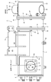
- FIG. 1 is a front sectional view of the exhaust gas purification device
- FIG. 2 is a bottom view of the same
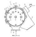
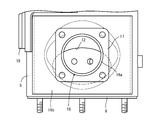
- FIG. 3 is a left side view of the exhaust gas inflow side
- FIG. 4 is a right side sectional view of the exhaust gas purification device
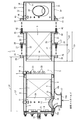
- FIG. 5 is an exploded front sectional view of FIG. 1
- FIG. 6 is an enlarged front sectional view of the exhaust gas discharge side
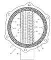
- FIG. 7 is an enlarged side sectional view of the exhaust gas discharge side
- FIG. FIG. 9 is an enlarged sectional view in plan view of the exhaust gas inflow side.
- the overall structure of the exhaust gas purification apparatus will be described with reference to FIGS. 1 to 5.
- the exhaust gas inflow side is simply referred to as the left side
- the exhaust gas discharge side is also simply referred to as the right side.
- a continuous regeneration type diesel particulate filter 1 (hereinafter referred to as DPF) is provided as an exhaust gas purifying apparatus of this embodiment.
- the DPF 1 is for physically collecting particulate matter (PM) and the like in the exhaust gas.
- the DPF 1 exhausts a diesel oxidation catalyst 2 such as platinum that generates nitrogen dioxide (NO2) and a soot filter 3 having a honeycomb structure that continuously oxidizes and removes the collected particulate matter (PM) at a relatively low temperature.
- the gas is arranged in series in the gas movement direction (from left to right in FIG. 1).
- the DPF 1 is configured so that the soot filter 3 is continuously regenerated.
- the DPF 1 can reduce carbon monoxide (CO) and hydrocarbons (HC) in the exhaust gas in addition to the removal of particulate matter (PM) in the exhaust gas.
- a diesel oxidation catalyst 2 as a gas purification filter for purifying exhaust gas discharged from an engine is installed in a substantially cylindrical catalyst inner case 4 made of a heat-resistant metal material.
- the catalyst inner case 4 is provided in a substantially cylindrical catalyst outer case 5 made of a heat-resistant metal material. That is, the catalyst inner case 4 is fitted on the outside of the diesel oxidation catalyst 2 via the mat-shaped ceramic fiber catalyst heat insulating material 6. Further, the catalyst outer case 5 is fitted on the outer side of the catalyst inner case 4 via a thin plate support 7 having an I-shaped end face. Note that the diesel oxidation catalyst 2 is protected by the catalyst heat insulating material 6. The stress (deformation force) of the catalyst outer case 5 transmitted to the catalyst inner case 4 is reduced by the thin plate support 7.
- a disc-shaped left lid 8 is fixed to the left ends of the catalyst inner case 4 and the catalyst outer case 5 by welding.
- a sensor connection plug 10 is fixed to the left lid body 8 through a seat plate body 9.
- the left end face 2a of the diesel oxidation catalyst 2 and the left lid 8 are opposed to each other with a predetermined distance L1 for gas inflow space.
- An exhaust gas inflow space 11 is formed between the left end face 2 a of the diesel oxidation catalyst 2 and the left lid 8.
- the sensor connection plug 10 is connected to an unillustrated inlet side exhaust gas pressure sensor, an inlet side exhaust gas temperature sensor, and the like.
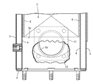
- an elliptical exhaust gas inlet 12 is opened at the left end of the catalyst inner case 4 and the catalyst outer case 5 in which the exhaust gas inflow space 11 is formed.
- the elliptical exhaust gas inlet 12 has a short diameter in the exhaust gas movement direction (center line direction of the cases 4 and 5) and a direction orthogonal to the exhaust gas movement direction (circumferential direction of the cases 4 and 5). It has a long diameter.
- a closing ring body 15 is fixed between the opening edge 13 of the catalyst inner case 4 and the opening edge 14 of the catalyst outer case 5 in a sandwiched manner. A gap between the opening edge 13 of the catalyst inner case 4 and the opening edge 14 of the catalyst outer case 5 is closed by the closing ring body 15.
- An exhaust ring 15 prevents the exhaust gas from flowing between the catalyst inner case 4 and the catalyst outer case 5.
- an exhaust gas inlet pipe 16 is disposed on the outer surface of the catalyst outer case 5 in which the exhaust gas inlet 12 is formed.
- An exhaust connection flange body 17 is welded to a true circular opening end portion 16 a on the small diameter side of the exhaust gas inlet pipe 16.
- the exhaust connection flange body 17 is fastened to an exhaust manifold 71 of a diesel engine 70 described later via bolts 18.
- a large circular opening end 16 b on the large diameter side of the exhaust gas inlet pipe 16 is welded to the outer surface of the catalyst outer case 5.
- the exhaust gas inlet pipe 16 is formed in a divergent shape (a trumpet shape) from the small-diameter-side perfect circular opening end 16a toward the large-diameter-side perfect circular opening end 16b.
- a large circular opening end 16 b is formed on the outer surface of the left end of the opening edge 14 of the catalyst outer case 5.
- the left end of is welded. That is, with respect to the elliptical exhaust gas inlet 12, the exhaust gas inlet pipe 16 (the large circular opening end 16b) is offset downstream of the exhaust gas movement (on the right side of the catalyst outer case 5).
- the elliptical exhaust gas inlet 12 is offset to the exhaust gas moving upstream side (the left side of the catalyst outer case 5) with respect to the exhaust gas inlet pipe 16 (the large circular opening end 16b).
- the catalyst outer case 5 is formed.
- the exhaust gas of the engine 70 enters the exhaust gas inlet pipe 16 from the exhaust manifold 71, enters the exhaust gas inflow space 11 from the exhaust gas inlet pipe 16 through the exhaust gas inlet 12, and the diesel oxidation catalyst 2. From the left end face 2a. Nitrogen dioxide (NO 2) is generated by the oxidation action of the diesel oxidation catalyst 2. Further, as shown in FIGS. 2 to 4, support legs 19 are welded to the outer peripheral surface of the catalyst outer case 5. When the DPF 1 is assembled to the engine 70, the catalyst outer case 5 is fixed to the cylinder head 72 of the engine 70, which will be described later, via the support legs 19.
- the soot filter 3 as a gas purification filter for purifying exhaust gas discharged from the engine 70 is provided in a substantially cylindrical filter inner case 20 made of a heat-resistant metal material.
- the inner case 4 is provided in a substantially cylindrical filter outer case 21 made of a heat-resistant metal material. That is, the filter inner case 20 is fitted on the outside of the soot filter 3 via the mat-shaped ceramic fiber filter heat insulating material 22. The soot filter 3 is protected by the filter heat insulating material 22.
- the catalyst side flange 25 is welded to the end of the catalyst outer case 5 on the downstream side (right side) of the exhaust gas movement.
- the filter-side flange 26 is welded to the middle of the filter inner case 20 in the exhaust gas movement direction and the end of the filter outer case 21 on the upstream side (left side) of the exhaust gas movement.
- the catalyst side flange 25 and the filter side flange 26 are detachably fastened by bolts 27 and nuts 28.
- the diameter of the cylindrical catalyst inner case 4 and the diameter of the cylindrical filter inner case 20 are substantially the same. Further, the diameter of the cylindrical catalyst outer case 5 and the diameter of the cylindrical filter outer case 21 are substantially the same.
- the exhaust gas movement downstream side (right side) end of the catalyst inner case 4 is shown in a state where the filter outer case 21 is connected to the catalyst outer case 5 via the catalyst side flange 25 and the filter side flange 26, the exhaust gas movement downstream side (right side) end of the catalyst inner case 4 is shown.
- the end portion on the upstream side (left side) of the exhaust gas movement of the filter inner case 20 faces the portion spaced apart by a fixed interval L2 for sensor attachment.
- the sensor mounting space 29 is formed between the exhaust gas movement downstream side (right side) end of the catalyst inner case 4 and the exhaust gas movement upstream side (left side) end of the filter inner case 20.
- a sensor connection plug 50 is fixed to the catalyst outer case 5 at the sensor mounting space 29 position.
- the sensor connection plug 50 is connected to a filter inlet side exhaust gas pressure sensor (not shown), a filter inlet side exhaust gas temperature sensor (thermistor), and the like.
- the cylindrical length L4 of the catalyst outer case 5 in the exhaust gas movement direction is longer than the cylindrical length L3 of the catalyst inner case 4 in the exhaust gas movement direction.
- the cylindrical length L6 of the filter outer case 21 in the exhaust gas movement direction is shorter than the cylindrical length L5 of the filter inner case 20 in the exhaust gas movement direction.
- a length (L2 + L3 + L5) obtained by adding the constant interval L2 of the sensor mounting space 29, the cylindrical length L3 of the catalyst inner case 4 and the cylindrical length L5 of the filter inner case 20 is the cylindrical length L4 of the catalyst outer case 5.
- nitrogen dioxide (NO2) generated by the oxidation action of the diesel oxidation catalyst 2 is supplied to the soot filter 3 from the left end face 3a.
- the collected particulate matter (PM) in the exhaust gas of the diesel engine 70 collected by the soot filter 3 is continuously oxidized and removed at a relatively low temperature by nitrogen dioxide (NO2).
- nitrogen dioxide (NO2) generated by the oxidation action of the diesel oxidation catalyst 2
- the collected particulate matter (PM) in the exhaust gas of the diesel engine 70 collected by the soot filter 3 is continuously oxidized and removed at a relatively low temperature by nitrogen dioxide (NO2).
- carbon monoxide (CO) and hydrocarbons (HC) in the exhaust gas of the diesel engine 70 are reduced.
- a diesel oxidation catalyst 2 or soot filter 3 as a gas purification filter for purifying exhaust gas discharged from a diesel engine 70, and a catalyst inner case in which the diesel oxidation catalyst 2 or soot filter 3 is installed.
- a filter inner case 20 a catalyst outer case 5 in which the catalyst inner case 4 and the filter inner case 20 are installed, and a filter outer case 21, a plurality of sets of diesel oxidation catalysts 2 and soot
- the filter 3, the catalyst inner case 4, the filter inner case 20, the catalyst outer case 5, and the filter outer case 21 are provided, and the catalyst outer case 5 and the filter outer case 21 with respect to the connection boundary position of the diesel oxidation catalyst 2 and the soot filter 3.
- Catalyst side flange 25 and fill as flange body connecting Since it is obtained by constituting the side flanges 26 so as to offset, by reducing the distance between the junction of the diesel oxidation catalyst 2 or the soot filter 3 can shorten the connection length of the catalyst outer case 5 and the filter outer case 21. Further, a gas sensor or the like can be easily arranged at the connection boundary position of the diesel oxidation catalyst 2 or the soot filter 3. Since the length of the catalyst outer case 5 and the filter outer case 21 in the exhaust gas movement direction can be shortened, the rigidity and weight reduction of the catalyst outer case 5 and the filter outer case 21 can be achieved.
- FIGS. 1 to 5 two types of diesel oxidation catalysts 2 and soot filters 3 are provided, and a filter inner case 20 in which one soot filter 3 is installed is provided in the catalyst of the other diesel oxidation catalyst 2. Since the catalyst outer case 5 in which the inner case 4 is installed is configured to overlap, the catalyst outer case 5 or the soot filter 3 is secured while maintaining the length of the diesel oxidation catalyst 2 or the soot filter 3 in the exhaust gas movement direction. The length of the filter outer case 21 in the exhaust gas movement direction can be shortened.
- the catalyst inner case 4 (the other diesel oxidation catalyst 2) where the catalyst outer case 5 overlaps is largely exposed to the outside by the separation (disassembly) of the catalyst outer case 5 and the filter outer case 21, the catalyst inner case 4 is exposed.
- the exposure range of the case 4 (the other diesel oxidation catalyst 2) is increased, and maintenance work such as soot removal of the one soot filter 3 can be easily performed.
- a diesel oxidation catalyst 2 and a soot filter 3 are provided as a plurality of sets of gas purification filters, and the catalyst side flange 25 and the filter side flange 26 are offset on the outer peripheral side of the soot filter 3. Therefore, by separating the catalyst outer case 5 and the filter outer case 21, the end of the inner case 20 on the exhaust gas inlet side of the soot filter 5 can be greatly exposed from the end surface of the outer case 21. Maintenance work such as removal of soot adhering to the case 20 can be easily performed.
- two types of diesel oxidation catalysts 2 and soot filters 3 are provided, and a catalyst inner case 4 in which one diesel oxidation catalyst 2 is installed, and the other soot filter 3 in the interior. Since the sensor mounting space 29 is formed between the filter inner case 20 and the filter outer case 20 to be provided, the connection length of the catalyst outer case 5 and the filter outer case 21 in the exhaust gas moving direction is shortened, and the catalyst outer case 5 is reduced. In addition, a gas sensor or the like can be easily arranged in the sensor mounting space 29 at the connection boundary position between the diesel oxidation catalyst 2 and the soot filter 3 while improving the rigidity and weight of the filter outer case 21 and the like.
- a sensor connection plug 50 as a sensor support is assembled to the catalyst outer case 5 that overlaps the filter inner case 20, and the sensor is installed at the connection boundary position of the diesel oxidation catalyst 2 and the soot filter 3. Since a gas sensor such as a filter inlet side exhaust gas pressure sensor or a filter inlet side exhaust gas temperature sensor (thermistor) (not shown) is arranged through the connection plug 50, the catalyst outer case 5 and the filter outer case are arranged.
- the sensor connection plug 50 can be compactly installed at the connection boundary position between the diesel oxidation catalyst 2 and the soot filter 3 while improving the rigidity and weight of the engine 21 and the like.
- a diesel oxidation catalyst 2 or soot filter 3 as a gas purification filter for purifying exhaust gas discharged from the diesel engine 70 and a diesel oxidation catalyst 2 or soot filter 3 are installed.
- An exhaust gas purifying apparatus comprising a catalyst inner case 4 or a filter inner case 20 as an inner case, and a catalyst outer case 5 or a filter outer case 21 as an outer case in which the catalyst inner case 4 or the filter inner case 20 is provided.
- an exhaust gas inlet 12 is formed on the peripheral surface of one end of the catalyst inner case 4 and the catalyst outer case 5, and an exhaust gas inlet pipe 16 is provided outside the exhaust gas inlet 12 in the outer periphery of the catalyst outer case 5.
- the exhaust gas inlet pipe 16 is more exhausted than the area of the open end face of the exhaust gas inlet pipe 16 on the exhaust gas inlet side.
- the area of the open end of the gas outlet side is larger. Therefore, the exhaust gas inlet pipe can be arranged near the diesel oxidation catalyst 2 installation portion, and the length of the catalyst outer case 5 (casing) on the exhaust gas upstream side of the diesel oxidation catalyst 2 in the exhaust gas movement direction can be easily reduced. That is, the end face of the diesel oxidation catalyst 2 can be easily brought close to the end face on the upstream side of the catalyst outer case 5 in the exhaust gas movement direction.
- the outer peripheral face of the catalyst outer case 5 is formed.
- the exhaust gas inlet pipe 16 can be welded, and without providing a reinforcing member for connecting the catalyst outer case 5 and the exhaust gas inlet pipe 16 as in the prior art, the exhaust gas inlet pipe 16 on the exhaust gas inlet side of the catalyst outer case 5 is provided. Exhaust gas pressure loss in the catalyst outer case 5 and the exhaust gas inlet pipe 16 can be reduced while maintaining the mounting strength.
- the exhaust gas outlet side edge of the exhaust gas inlet pipe 16 is fixed to the outer peripheral surface of the exhaust gas inlet of the catalyst outer case 5.
- the exhaust gas inlet pipe 16 is configured to be offset from the gas inlet 12 to the exhaust gas downstream side of the catalyst outer case 5. Therefore, the exhaust gas upstream end face of the diesel oxidation catalyst 2 can be disposed upstream of the exhaust gas downstream side opening edge of the exhaust gas inlet pipe 16 and the length of the catalyst outer case 5 in the exhaust gas moving direction. Of these, the length upstream of the exhaust gas can be easily reduced.
- the length of the catalyst outer case 5 in the exhaust gas movement direction can be made compact.
- the exhaust gas outlet side of the exhaust gas inlet pipe 16 can be disposed away from the upstream side end surface of the catalyst outer case 5 in the exhaust gas movement direction.
- the exhaust gas inlet in the exhaust gas movement direction of the catalyst outer case 5 is larger than the opening size of the exhaust gas inlet 12 of the catalyst outer case 5 and the catalyst inner case 4.
- the opening size on the exhaust gas outlet side of the pipe 16 is made large. Therefore, the attachment strength of the exhaust gas inlet pipe 16 on the exhaust gas inlet side of the catalyst outer case 5 can be maintained without providing a reinforcing member as in the prior art, and the exhaust gas inlet pipe 16 or the exhaust gas inlet of the catalyst outer case 5 can be maintained. Exhaust pressure loss of 12 etc. can be reduced. Compared to a conventional structure provided with a reinforcing member, the number of components can be reduced and the structure can be reduced.
- the exhaust gas inlet side such as the catalyst outer case 5 and the exhaust gas inlet pipe 16 can be configured with high rigidity. That is, the exhaust gas inlets of the catalyst outer case 5 and the catalyst inner case 4 can be formed close to the upstream side end face of the catalyst outer case 5 in the exhaust gas movement direction.
- the exhaust gas movement of the diesel oxidation catalyst 2 or the soot filter 3 rather than the end of the exhaust gas outlet side of the exhaust gas inlet pipe 16 on the downstream side of the exhaust gas movement.
- the upstream end surface is configured to be disposed on the exhaust gas movement upstream side of the catalyst outer case 5. Therefore, the length of the catalyst outer case 5 in the exhaust gas movement direction can be easily reduced, and the length of the catalyst outer case 5 in the exhaust gas movement direction can be made compact.
- the exhaust gas inlet is connected to the opening edge of the exhaust gas inlet 12 upstream of the exhaust gas movement. Since the exhaust gas outlet side end of the pipe 16 is connected, the length on the exhaust gas upstream side of the length of the catalyst outer case 5 in the exhaust gas movement direction can be easily reduced. However, the exhaust pressure loss of the exhaust gas in the catalyst outer case 5 and the exhaust gas inlet pipe 16 can be reduced.
- the diesel oxidation catalyst 2 and the soot filter 3 are provided as gas purification filters for purifying the exhaust gas discharged from the engine.
- urea reducing agent
- NOx selective reduction catalyst NOx removal catalyst
- NH3 ammonia
- NOx removal catalyst a NOx selective reduction catalyst
- ammonia removal catalyst is provided in the filter inner case 20 as a gas purification filter
- nitrogen oxidation in the exhaust gas exhausted by the engine is performed.
- the substance (NOx) is reduced and can be discharged as harmless nitrogen gas (N2).
- a diesel oxidation catalyst 2 or soot filter 3 as a gas purification filter for purifying exhaust gas discharged from a diesel engine 70, and a catalyst inner case in which the diesel oxidation catalyst 2 or soot filter 3 is installed.
- a filter inner case 20, and a catalyst outer case 5 and a filter outer case 21 in which the catalyst inner case 4 and the filter inner case 20 are installed. Are connected to the catalyst outer case 5 and the filter outer case 21, and an exhaust gas inlet pipe 16 as an inlet component to which an external stress is applied and a support leg 19 as a support body are arranged on the catalyst outer case 5. Yes.
- the double structure of the catalyst inner case 4 or the filter inner case 20 and the catalyst outer case 5 or the filter outer case 21 improves the heat insulating properties of the diesel oxidation catalyst 2 or the soot filter 3, thereby treating the diesel oxidation catalyst 2 or the soot filter 3.
- a plurality of sets of diesel oxidation catalysts 2 and soot filters 3, a catalyst inner case 4 and a filter inner case 20, and a catalyst outer case 5 and a filter outer case 21 are provided.
- the case 5 and the filter outer case 21 are connected by a catalyst side flange 25 and a filter side flange 26 as flange bodies. Accordingly, in consideration of the configuration of the exhaust gas inlet pipe 16 and the support leg 19 and the movement of exhaust gas between the plurality of sets of diesel oxidation catalyst 2 and the soot filter 3, a plurality of sets of catalyst inner cases 4 and filter inner cases are used.
- 20 and a plurality of sets of the catalyst outer case 5 and the filter outer case 21 can be functionally configured.
- the processing capacity, regeneration capacity, etc. of a plurality of sets of diesel oxidation catalysts 2 and soot filters 3 can be easily improved.
- the length of the catalyst inner case 4 and the filter inner case 20 in the exhaust gas moving direction is different from the length of the catalyst outer case 5 and the filter outer case 21 in the exhaust gas moving direction. Yes. Accordingly, the flange body connecting the catalyst outer case 5 and the filter outer case 21 can be offset with respect to the joining position of the plurality of sets of the diesel oxidation catalyst 2 and the soot filter 3.
- the mounting interval of the plurality of sets of diesel oxidation catalysts 2 and soot filters 3 can be easily reduced or expanded.
- a plurality of sets of diesel oxidation catalysts 2 and soot filters 3, a catalyst inner case 4 and a filter inner case 20, a catalyst outer case 5 and a filter outer case 21 are provided.
- the soot filter 3 is configured such that the catalyst side flange 25 and the filter side flange 26 connecting the plurality of sets of the catalyst outer case 5 and the filter outer case 21 are offset with respect to the joining position of the catalyst 2 and the soot filter 3.
- a catalyst outer case 5 facing the other diesel oxidation catalyst 2 is configured to overlap with the filter inner case 20 facing the other.
- a sensor or the like can be easily arranged between the joints of the plurality of sets of the diesel oxidation catalyst 2 and the soot filter 3 while the joint interval between the plurality of sets of the diesel oxidation catalyst 2 and the soot filter 3 can be reduced.
- the lengths of the plurality of sets of catalyst outer cases 5 and filter outer cases 21 in the exhaust gas movement direction can be shortened, and the rigidity and weight of the plurality of sets of catalyst outer cases 5 and filter outer cases 21 can be improved.
- the length of the plurality of sets of catalyst outer case 5 and filter outer case 21 in the exhaust gas moving direction can be shortened.
- a diesel oxidation catalyst 2 or soot filter 3 as a gas purification filter for purifying exhaust gas discharged from a diesel engine 70, and a diesel oxidation catalyst 2 or soot filter 3 are provided.
- the catalyst inner case 4 or the filter inner case 20 as an inner case to be installed inside, and the catalyst outer case 5 or the filter outer case 21 as an outer case into which the catalyst inner case 4 or the filter inner case 20 is installed are provided.
- an exhaust gas inlet pipe 16 is disposed outside the catalyst outer case 5 and is opposed to the exhaust gas outlet side of the exhaust gas inlet pipe 16 so as to face the catalyst inner case 4 or the filter inner case 20 and the catalyst outer case 5 or the filter outer side.
- the exhaust gas inlet 12 is opened in the case 21, and between the end face of the catalyst outer case 5 upstream of the catalyst outer case 5 or the filter outer case 21 in the exhaust gas movement direction and the end face of the diesel oxidation catalyst 2 or the soot filter 3.
- the exhaust gas inflow space 11 is formed as a rectifying chamber, and the exhaust gas inflow space 11 is communicated with the exhaust gas inlet pipe 16 via the exhaust gas inlet 12. Therefore, for example, in the structure in which the exhaust gas of the diesel engine 70 is introduced into the catalyst inner case 4 from the shear direction orthogonal to the center line thereof, it is not necessary to insert the exhaust gas inlet pipe 16 into the exhaust gas inflow space 11. .
- the number of components of the structure of the catalyst outer case 5 provided with the exhaust gas inlet pipe 16 can be reduced and the cost can be reduced, and the catalyst inner case 4 or the filter inner side on the exhaust gas upstream side of the diesel oxidation catalyst 2 or the soot filter 3.
- the length of the case 20 and the catalyst outer case 5 or the filter outer case 21 in the exhaust gas moving direction can be easily shortened. That is, the relative distance between the exhaust gas inlet side of the diesel oxidation catalyst 2 and the upstream end face of the catalyst inner case 4 and the catalyst outer case 5 facing the exhaust gas moving direction can be easily shortened.
- the diesel oxidation catalyst 2 can be disposed close to the end surfaces of the catalyst inner case 4 and the catalyst outer case 5 on the upstream side of the exhaust gas movement, and the exhaust of the catalyst inner case 4 or the filter inner case 20 and the catalyst outer case 5 or the filter outer case 21
- the number of parts can be reduced as compared with the prior art, and the structure can be made compact and lightweight at low cost.
- the exhaust gas movement direction is larger than the opening size of the exhaust gas inlet 12 of the catalyst outer case 5 in the catalyst outer case 5 or the filter outer case 21 in the exhaust gas movement direction. Since the opening size of the exhaust gas inlet 12 in the direction perpendicular to the catalyst is formed large, the catalyst inner case 4 or the filter inner case 20 is maintained while maintaining the rigidity of mounting the exhaust gas inlet pipe 16 to the catalyst outer case 5. In addition, the size of the catalyst outer case 5 or the filter outer case 21 in the exhaust gas movement direction can be shortened, so that the number of parts can be reduced as compared with the conventional case, and the structure can be made compact and lightweight at low cost.
- the exhaust gas inlet is larger than the opening size of the exhaust gas outlet of the exhaust gas inlet pipe 16 in the exhaust gas movement direction of the catalyst outer case 5 or the filter outer case 21. Since the opening size of 12 is made small, the exhaust gas can be evenly supplied from the exhaust gas inflow space 11 to the exhaust gas inlet side of the diesel oxidation catalyst 2, and while maintaining the gas purification function of the diesel oxidation catalyst 2,
- the catalyst inner case 4 or the filter inner case 20 and the catalyst outer case 5 or the filter outer case 21 can be configured to be compact and lightweight.
- the opening shape of the exhaust gas inlet 12 is formed into an elliptical shape, a rectangular shape, a long hole shape, or a similar shape thereof, and the outside of the catalyst is formed.
- the opening size of the exhaust gas inlet 12 of the catalyst outer case 5 in the exhaust gas movement direction of the case 5 or the filter outer case 21 and the opening diameter size of the exhaust gas inlet pipe 16 on the exhaust gas inlet side are formed to be approximately equal. Therefore, the opening area of the exhaust gas inlet 12 can be made larger than the opening area of the exhaust gas inlet pipe 16 on the exhaust gas inlet side.
- the exhaust gas can be moved from the exhaust gas inlet 12 into the exhaust gas inflow space 11 while dispersing the exhaust gas in a direction orthogonal to the exhaust gas movement direction of the diesel oxidation catalyst 2. Can be reduced.
- the end of the exhaust gas inlet pipe 16 on the exhaust gas outlet side is formed at the opening edge of the exhaust gas inlet 12 on the upstream side of the exhaust gas movement among the opening edges of the exhaust gas inlet 12. are connected.
- the exhaust gas can be dispersed in the direction orthogonal to the exhaust gas movement direction of the diesel oxidation catalyst 2, and the exhaust gas can be evenly moved from the exhaust gas inlet 12 to the exhaust gas inlet side of the diesel oxidation catalyst 2.
- the drift of the exhaust gas with respect to the diesel oxidation catalyst 2 can be reduced, and the exhaust gas purification ability of the diesel oxidation catalyst 2 can be improved.
- the silencer 30 for attenuating the exhaust gas sound discharged from the diesel engine 70 includes a substantially cylindrical silencer inner case 31 made of a heat resistant metal material, and an abbreviation made of a heat resistant metal material. It has a cylindrical silencing outer case 32 and a disc-shaped right lid 33 fixed to the right end of the silencing inner case 31 and the silencing outer case 32 by welding.
- a silencer inner case 31 is provided in the silencer outer case 32.
- the diameter of the cylindrical catalyst outer case 5, the diameter of the cylindrical filter outer case 21, and the cylindrical silencing outer case 32 are substantially the same.
- the diameter size of the cylindrical catalyst inner case 4, the diameter size of the cylindrical filter inner case 20, and the cylindrical sound deadening inner case 31 are substantially the same size.
- the diameter size of the cylindrical catalyst inner case 4, the diameter size of the cylindrical filter inner case 20, and the cylindrical silencer inner case 31 may not be the same size.
- an exhaust gas outlet pipe 34 is passed through the silencer inner case 31 and the silencer outer case 32.
- One end side of the exhaust gas outlet pipe 34 is closed by an outlet lid 35.
- a number of exhaust holes 36 are formed in the entire exhaust gas outlet pipe 34 inside the silencer inner case 31.
- the interior of the muffler inner case 31 is communicated with an exhaust gas outlet pipe 34 via a number of exhaust holes 36.
- a silencer and a tail pipe (not shown) are connected to the other end side of the exhaust gas outlet pipe 34.
- a number of silencing holes 37 are opened in the silencing inner case 31.
- the interior of the silencer inner case 31 is communicated between the silencer inner case 31 and the silencer outer case 32 via a number of silencer holes 37.
- the space between the silencer inner case 31 and the silencer outer case 32 is closed by the right lid 33 and the thin plate support 38.
- a ceramic fiber silencer 39 is filled between the silencer inner case 31 and the silencer outer case 32.
- the exhaust gas movement upstream (left side) end of the muffler inner case 31 is connected to the exhaust gas movement upstream (left side) end of the muffler outer case 32 via a thin plate support 38.
- exhaust gas is discharged from the muffler inner case 31 through the exhaust gas outlet pipe 34. Further, in the silencer inner case 31, exhaust gas sounds (mainly high frequency band sounds) are absorbed into the silencer 39 from the numerous silencer holes 37. The noise of the exhaust gas discharged from the outlet side of the exhaust gas outlet pipe 34 is attenuated.
- exhaust gas sounds mainly high frequency band sounds
- the filter side outlet flange 40 is welded to the exhaust gas movement downstream side (right side) end of the filter inner case 20 and the filter outer case 21.
- the silencer flange 41 is welded to the exhaust gas movement upstream side (left side) of the silencer outer case 32.
- the filter side outlet flange 40 and the silencer side flange 41 are detachably fastened by bolts 42 and nuts 43.
- a sensor connection plug 44 is fixed to the filter inner case 20 and the filter outer case 21.
- the sensor connection plug 44 is connected to an unillustrated outlet side exhaust gas pressure sensor, an outlet side exhaust gas temperature sensor (thermistor) and the like.
- a diesel oxidation catalyst 2 or soot filter 3 as a gas purification filter for purifying exhaust gas discharged from the diesel engine 70, and a diesel oxidation catalyst 2 or soot filter 3 are provided.
- Exhaust gas comprising a catalyst inner case 4 or filter inner case 20 as an inner case to be installed inside, and a catalyst outer case 5 or filter outer case 21 as an outer case in which the catalyst inner case 4 or filter inner case 20 is installed.
- the gas purification apparatus includes a silencer 39 as an exhaust sound attenuator that attenuates the exhaust sound of the exhaust gas discharged from the diesel engine 70, and the silencer at the exhaust gas outlet side end of the catalyst outer case 5 or the filter outer case 21.
- the diesel oxidation catalyst 2 or the soot filter 3 While maintaining the exhaust gas purification function, without changing the structure of the diesel oxidation catalyst 2 or the soot filter 3 can be easily added to mute the exhaust gas.
- an exhaust structure in which a tail pipe is directly connected to the outer case an exhaust structure that further improves the silencing function of an existing silencer, and the like can be easily configured.
- a silencing structure (silencing material 39) formed by punch holes and a fibrous mat can be easily installed.
- the silencer 30 having the silencer 39 is provided as shown in FIGS. 5 to 7 and the silencer 30 is detachably connected to the exhaust gas outlet side end of the filter outer case 21, By attaching / detaching the silencer 30, the exhaust gas silencing function in the diesel oxidation catalyst 2 or the soot filter 3 can be easily changed.
- a silencer 30 having a silencer 39 is provided, and the catalyst outer case 5 or the filter outer case 21 and the silencer 30 are formed in a cylindrical shape having substantially the same outer diameter, respectively.
- a filter-side outlet flange 40 as a ring-shaped flange body is provided at an end portion of the exhaust gas outlet side of 21, and a silencer 39 is attached to an end portion of the exhaust gas outlet side of the filter outer case 21 via the filter-side outlet flange 40. Since the silencer 30 having substantially the same outer diameter is connected to the filter outer case 21 by the filter-side outlet flange 40, the catalyst outer case is arranged in the exhaust gas moving direction.
- the filter outer case 21 can be assembled in a compact manner simply by lengthening the mounting dimension of the filter outer case 21.
- the catalyst outer case 5 or the filter outer case 21 can be easily installed close to the side surface of the exhaust gas discharge part of the diesel engine 70.
- the high frequency reduction measures of exhaust gas can be easily implemented by installing the silencer 39 while improving the gas purification function of the diesel oxidation catalyst 2 or the soot filter 3 by maintaining the temperature of the exhaust gas.
- the silencer inner case 31 and the silencer outer case 32 as silencer casings in which the silencer 39 is incorporated, the one end side is closed, and the other end side is communicated with a tail pipe (not shown).
- An exhaust gas outlet pipe 34, and the silencer inner case 31 and the silencer outer case 32 are passed through the exhaust hole 36 forming portion of the exhaust gas outlet pipe 34, and the filter side outlet of the filter outer case 21 is connected to the filter side outlet. Since the silencer inner case 31 and the silencer outer case 32 are detachably connected via the flange 40, the diesel oxidation catalyst 2 or the soot filter can be removed by attaching and detaching the silencer inner case 31 and the silencer outer case 32.
- the exhaust gas silencing function in the third section It is possible to easily change the exhaust gas silencing function in the third section.
- a silencer (not shown) separately from the silencer inner case 31 and the silencer outer case 32, an exhaust structure that further improves the exhaust gas silencer function can be easily configured.
- the exhaust structure in which the tail pipe (not shown) is directly connected to the filter outer case 21 can be easily configured by the arrangement of the silencer inner case 31 and the silencer outer case 32 in which the silencer 39 is not incorporated.
- a silencer 39 (punch hole and fibrous mat, etc.) is provided in the silencer inner case 31 and the silencer outer case 32. )
- the muffler structure can be configured easily.
- the silencer casing has a cylindrical silencer inner case 31 and a cylindrical silencer outer case 32, and the silencer inner case 31 is arranged in the silencer outer case 32, and the silencer inner case is arranged. Since the silencer 39 is filled between the silencer 31 and the silencer outer case 32 and a number of silencer holes 37 are formed in the silencer inner case 31, the catalyst inner case 4 in which the diesel oxidation catalyst 2 or the soot filter 3 is installed.
- the silencer casing (the silencer inner case 31 and the silencer outer case 32) can be configured by approximating an exhaust gas purification structure including the filter inner case 20, the catalyst outer case 5, or the filter outer case 21.
- the silencer casing is silenced by using the same material (pipe or the like) as the catalyst inner case 4 or the filter inner case 20, the catalyst outer case 5 or the filter outer case 21 for installing the diesel oxidation catalyst 2 or the soot filter 3.
- the inner case 31 and the silencer outer case 32 can be formed. The manufacturing cost of the silencer casing can be easily reduced.
- the exhaust gas inlet 12 is formed by opening substantially elliptical through holes in the catalyst inner case 4 and the catalyst outer case 5.
- the exhaust gas inlet 12 can be formed by opening substantially rectangular through holes in the catalyst inner case 4 and the catalyst outer case 5.
- the exhaust gas inlet 12 can be formed by opening a substantially oval through hole in the catalyst inner case 4 and the catalyst outer case 5.
- the exhaust gas inlet 12 can be formed by opening substantially polygonal through holes in the catalyst inner case 4 and the catalyst outer case 5. Further, as shown in FIG.
- the exhaust gas inlet 12 can be formed by opening substantially hexagonal through holes in the catalyst inner case 4 and the catalyst outer case 5. Further, as shown in FIG. 14, the exhaust gas inlet 12 can be formed by opening an indeterminate through hole in the catalyst inner case 4 and the catalyst outer case 5.
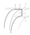
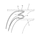
- the inner case support 7 will be described with reference to FIGS. 1, 5, and 23 to 27.
- the cylindrical catalyst outer case 5 is fitted on the outer side of the cylindrical catalyst inner case 4 via a ring-shaped thin plate inner case support 7 having an I-shaped end face.
- the stress (deformation force) of the catalyst outer case 5 is reduced by the thin plate inner case support 7.
- the inner case support 7 includes an I-shaped thin plate portion 7a and an outer case connecting portion 7b. The inner edge of the I-shaped thin plate portion 7a is welded to the outer surface of the catalyst inner case 4 on the downstream side of the exhaust gas movement.
- the I-shaped thin plate portion 7 a is erected substantially vertically on the outer surface of the catalyst inner case 4, and the I-shaped thin plate portion 7 a protrudes radially from the outer surface of the catalyst inner case 4.
- the outer case connecting portion 7b is extended from the outer diameter side edge of the I-shaped thin plate portion 7a in a direction bent substantially at a right angle.
- the cross-sectional end surface of the inner case support 7 is formed in an L shape by the I-shaped thin plate portion 7a and the outer case connecting portion 7b.
- the end of the outer case connecting portion 7b is extended in the exhaust gas moving direction (in the direction of the center line of the cylindrical case 5).
- the outer case connecting portion 7b is welded to the inner surface of the intermediate portion of the catalyst outer case 5 in the exhaust gas movement direction through the welding hole 5a opened in the catalyst outer case 5.
- the welding hole 5a is closed by welding the outer case connecting portion 7b. That is, as shown in FIGS. 1 and 23, the diesel oxidation catalyst 2 or the soot filter 3 as a gas purification filter for purifying the exhaust gas discharged from the diesel engine 70, and the inside in which the diesel oxidation catalyst 2 or the soot filter 3 is installed.
- an exhaust gas purification apparatus comprising a catalyst inner case 4 or a filter inner case 20 as a case, and a catalyst outer case 5 or a filter outer case 21 as an outer case in which the catalyst inner case 4 or the filter inner case 20 is provided.
- a ring-shaped inner case support 7 is provided between the catalyst inner case 4 and the catalyst outer case 5, and the inner case support 7 is formed of a flexible material having a vibration damping function.
- the outer case 5 is configured to support the catalyst inner case 4 via the inner case support 7. .
- the vibration of the catalyst outer case 5 is damped by the inner case support 7 and the vibration transmitted from the catalyst outer case 5 to the catalyst inner case 4 can be reduced, the sealing performance of the diesel oxidation catalyst 2 is reduced, and the catalyst outer case 5 is reduced.
- damage or dropout of the catalyst inner case 4 or the diesel oxidation catalyst 2 can be easily prevented. That is, the durability of the diesel oxidation catalyst 2 can be improved by reducing the sealing performance of the catalyst outer case 5 or the catalyst inner case 4.
- the maintenance workability of the soot filter 3 can be easily improved even with a filter configuration in which the exhaust gas purification capability is increased.
- the temperature of the catalyst inner case 4 (diesel oxidation catalyst 2) can be easily managed by the heat insulating action of the space between the catalyst inner case 4 and the catalyst outer case 5.
- the temperature of the diesel oxidation catalyst 2 can be maintained at an appropriate catalyst temperature (about 300 to 500 degrees).
- the inner case support 7 is formed by a thin plate having an I-shaped cross section, and one end of the inner case support 7 is extended in a direction along the inner surface of the catalyst outer case 5.
- the outer case connecting portion 7b to be welded to the catalyst outer case 5 is formed on the extended portion on one end side of the inner case support 7, and the outer case connecting portion 7b is fixed to the inner surface of the catalyst outer case 5. Therefore, with the other end of the inner case support 7 welded to the outer surface of the catalyst inner case 4, the catalyst inner case 4 is inserted into the catalyst outer case 5, and the catalyst is removed from the outside of the catalyst outer case 5.
- the outer case connecting portion 7 b can be welded to the outer case 5.
- the inner case support 7 can be formed by a thin plate having a thickness that is not limited to the welding operation. Assembly workability of the catalyst outer case 5 and the catalyst inner case 4 can be improved.
- a plurality of diesel oxidation catalysts 2 or soot filters 3, a catalyst inner case 4 or filter inner case 20, and a catalyst outer case 5 or filter outer case 21 are provided.
- One soot is configured so that the catalyst side flange 25 or the filter side flange 26 as a flange body connecting the catalyst outer case 5 or the filter outer case 21 is offset with respect to the joining position of the oxidation catalyst 2 or the soot filter 3. Since the catalyst inner case 20 facing the filter 3 is configured to overlap the catalyst outer case 5 facing the other diesel oxidation catalyst 2, the exhaust of the plurality of diesel oxidation catalysts 2 or the soot filters 3 is configured.
- the plurality of catalyst outer casings are secured while ensuring the installation length in the gas movement direction.
- Scan 5 or can reduce the exhaust gas moving direction of the length of the filter outer case 21 can be improved and weight reduction of the rigidity of such a plurality of catalyst outer case 5 or the filter outer case 21.
- the filter inner case 20 (the soot filter 3 on the exhaust gas movement downstream side) where the catalyst outer case 5 overlaps can be largely exposed to the outside by the separation (disassembly) of the catalyst outer case 5 or the filter outer case 21.
- the exposure range of the exhaust gas movement upstream end portion (the filter inner case 20 on the exhaust gas movement downstream side) of the soot filter 3 arranged on the exhaust gas movement downstream side of the plurality of diesel oxidation catalysts 2 or the soot filters 3 is set.
- Maintenance work such as soot removal of the soot filter 3 on the downstream side of the exhaust gas movement can be easily performed.
- Maintenance workability such as cleaning of the soot filter 3 performed by separating the catalyst outer case 5 or the filter outer case 21 (catalyst inner case 4 or filter inner case 20) at the connecting portion of the catalyst side flange 25 or the filter side flange 26. It can be improved.
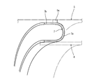
- the inner case support 7 is formed by a ring-shaped thin plate having an I-shaped end surface.
- the inner case support 7 is formed by a thin plate having a U-shaped end surface. May be.
- the inner case support 7 may be formed of a ring-shaped thin plate having an S-shaped end face.
- the inner case support 7 may be formed of a ring-shaped thin plate having an end face Z-shape.
- the inner case support 7 may be formed of a ring-shaped thin plate having a composite end face combining a Z-shape and an S-shape.
- the inner case support 7 has an I-shaped thin plate (see FIG. 23), a U-shaped thin plate (see FIG. 24), or an S-shaped cross-sectional end surface. Either a thin plate (see FIG. 25) or a cross-sectional end surface is formed by a Z-shaped thin plate (see FIG. 26), and the catalyst inner case 4 is elastically supported by the catalyst outer case 5 via the inner case support 7.
- a plurality of sets of catalyst outer case 5 or filter outer case 21 and catalyst inner case 4 or filter inner case 20 are provided, and a plurality of diesel oxidation catalysts 2 or soot filters 3 are combined.
- the inner side of the catalyst inside the catalyst outer case 5 in the exhaust gas movement direction is disposed inside the catalyst via the inner case support 7.
- the outer surface of the exhaust gas moves downstream end of the over scan 4 can be supported with high rigidity. Maintenance workability of the exhaust gas movement upstream end portion of the soot filter 3 arranged on the downstream side of the exhaust gas movement can be easily improved. Further, the sealing performance of the diesel oxidation catalyst 2 or the soot filter 3 is reduced, or the catalyst outer case 5 or the filter outer case 21 or the catalyst inner case 4 or the filter inner case 20 or the diesel oxidation catalyst 2 or the soot filter 3 is damaged or dropped off. Can be easily prevented.
- the inner case support is a thin plate having an I-shaped cross-section end face (see FIG. 23), a thin plate having a U-shaped cross-section end face (see FIG. 24), or a thin plate having an S-shaped cross-section end face (see FIG. 25), or a cross-sectional end face is formed by a thin plate (see FIG. 27) of any two or more of Z-shaped thin plates (see FIG. 26), and the catalyst outer case 5 via the inner case support 7 Therefore, for example, a plurality of sets of the catalyst outer case 5 or the filter outer case 21 and the catalyst inner case 4 or the filter inner case 20 are provided, and a plurality of diesel oxidation catalysts are provided.
- the filter 2 or soot filter 3 is combined with the inner casing on the inner surface side of the catalyst outer case 5 in the exhaust gas movement direction, even if the filter structure has a higher exhaust gas purification capability.
- the scan support 7 it can support the outer surface side of the exhaust gas moves downstream end of the catalyst inner case 4 with high rigidity. Maintenance workability of the exhaust gas movement upstream end portion of the soot filter 3 arranged on the downstream side of the exhaust gas movement can be easily improved. Further, the sealing performance of the diesel oxidation catalyst 2 or the soot filter 3 is deteriorated, or the catalyst outer case 5 or the filter outer case 21 or the catalyst inner case 4 or the filter inner case 20 or the diesel oxidation catalyst 2 or the soot filter 3 is damaged or dropped off. Can be easily prevented.
- FIGS. 15 to 18 A structure in which the DPF 1 is provided in the diesel engine 70 will be described with reference to FIGS.
- an exhaust manifold 71 and an intake manifold 73 are arranged on the left and right side surfaces of the cylinder head 72 of the diesel engine 70.
- the cylinder head 72 is mounted on a cylinder block 75 having an engine output shaft 74 (crankshaft) and a piston (not shown).
- the front end and the rear end of the engine output shaft 74 are projected from the front and rear surfaces of the cylinder block 75.
- a cooling fan 76 is provided on the front surface of the cylinder block 75. The rotational force is transmitted from the front end side of the engine output shaft 74 to the cooling fan 76 via the V belt 77.
- a flywheel housing 78 is fixed to the rear surface of the cylinder block 75.
- a flywheel 79 is installed in the flywheel housing 78.
- a flywheel 79 is pivotally supported on the rear end side of the engine output shaft 74.
- the power of the diesel engine 70 is taken out via a flywheel 79 to operating parts such as a backhoe 100 and a forklift 120 described later.
- the support leg 19 is detachably fastened to the cylinder head 72 with a bolt 80.
- the DPF 1 described above is configured to be supported by the highly rigid cylinder head 72 via the support leg 19.
- the backhoe 100 includes a crawler-type traveling device 102 having a pair of left and right traveling crawlers 103, and a turning machine body 104 provided on the traveling device 102.
- the revolving machine body 104 is configured to be horizontally revolved over 360 ° in all directions by a revolving hydraulic motor (not shown).
- An earthwork plate 105 for ground work is mounted on the rear part of the traveling device 102 so as to be movable up and down.
- a steering unit 106 and a diesel engine 70 are mounted on the left side of the revolving machine body 104.
- a working unit 110 having a boom 111 and a bucket 113 for excavation work is provided on the right side of the revolving machine body 104.
- the control unit 106 is provided with a control seat 108 on which an operator is seated, an operation means for operating the diesel engine 70 and the like, and a lever or switch as an operation means for the working unit 110.
- a boom cylinder 112 and a bucket cylinder 114 are arranged on a boom 111 which is a component of the working unit 110.
- a bucket 113 as an attachment for excavation is pivotally attached to the tip end portion of the boom 111 so as to be inserted and rotated.
- the boom cylinder 112 or the bucket cylinder 114 is operated to perform earthwork work (ground work such as grooving) by the bucket 113.
- the forklift car 120 includes a traveling machine body 124 having a pair of left and right front wheels 122 and a rear wheel 123.
- the traveling body 124 is equipped with a control unit 125 and a diesel engine 70.
- a working portion 127 having a fork 126 for handling work is provided on the front side portion of the traveling machine body 124.
- the control unit 125 is provided with a control seat 128 on which an operator is seated, a control handle 129, operation means for operating the diesel engine 70 and the like, a lever or switch as an operation means for the work unit 127, and the like. .
- a fork 126 is disposed on the mast 130, which is a component of the working unit 127, so as to be movable up and down.
- the fork 126 is moved up and down, a pallet (not shown) loaded with a load is placed on the fork 126, the traveling machine body 124 is moved forward and backward, and a cargo handling operation such as transportation of the pallet is performed. Yes.
Landscapes
- Engineering & Computer Science (AREA)
- Chemical & Material Sciences (AREA)
- Combustion & Propulsion (AREA)
- Mechanical Engineering (AREA)
- General Engineering & Computer Science (AREA)
- Chemical Kinetics & Catalysis (AREA)
- Health & Medical Sciences (AREA)
- Toxicology (AREA)
- Environmental & Geological Engineering (AREA)
- Analytical Chemistry (AREA)
- General Chemical & Material Sciences (AREA)
- Oil, Petroleum & Natural Gas (AREA)
- Biomedical Technology (AREA)
- Exhaust Gas After Treatment (AREA)
- Processes For Solid Components From Exhaust (AREA)
- Exhaust Gas Treatment By Means Of Catalyst (AREA)
Priority Applications (3)
| Application Number | Priority Date | Filing Date | Title |
|---|---|---|---|
| EP09814489.2A EP2333264B1 (en) | 2008-09-18 | 2009-09-07 | Exhaust gas purifying device |
| US12/737,897 US8580003B2 (en) | 2008-09-18 | 2009-09-07 | Exhaust gas purifying device |
| CN200980136489.2A CN102159811B (zh) | 2008-09-18 | 2009-09-07 | 排气净化装置 |
Applications Claiming Priority (2)
| Application Number | Priority Date | Filing Date | Title |
|---|---|---|---|
| JP2008-239408 | 2008-09-18 | ||
| JP2008239408A JP5185751B2 (ja) | 2008-09-18 | 2008-09-18 | 排気ガス浄化装置 |
Publications (1)
| Publication Number | Publication Date |
|---|---|
| WO2010032644A1 true WO2010032644A1 (ja) | 2010-03-25 |
Family
ID=42039471
Family Applications (1)
| Application Number | Title | Priority Date | Filing Date |
|---|---|---|---|
| PCT/JP2009/065598 WO2010032644A1 (ja) | 2008-09-18 | 2009-09-07 | 排気ガス浄化装置 |
Country Status (6)
| Country | Link |
|---|---|
| US (1) | US8580003B2 (zh) |
| EP (1) | EP2333264B1 (zh) |
| JP (1) | JP5185751B2 (zh) |
| KR (1) | KR101592300B1 (zh) |
| CN (2) | CN102159811B (zh) |
| WO (1) | WO2010032644A1 (zh) |
Cited By (1)
| Publication number | Priority date | Publication date | Assignee | Title |
|---|---|---|---|---|
| CN113950572A (zh) * | 2019-06-04 | 2022-01-18 | 株式会社丰田自动织机 | 配管的固定构造 |
Families Citing this family (13)
| Publication number | Priority date | Publication date | Assignee | Title |
|---|---|---|---|---|
| JP5390281B2 (ja) * | 2009-07-02 | 2014-01-15 | ヤンマー株式会社 | 排気ガス浄化装置 |
| US9010096B2 (en) * | 2012-08-24 | 2015-04-21 | Tenneco Automotive Operating Company Inc. | Exhaust component mounting system |
| JP6033026B2 (ja) * | 2012-09-28 | 2016-11-30 | ヤンマー株式会社 | エンジン装置 |
| US9050559B2 (en) * | 2013-03-01 | 2015-06-09 | Caterpillar Inc. | System and method for accommodating aftertreatment bricks |
| FR3007110B1 (fr) * | 2013-06-18 | 2017-08-25 | Peugeot Citroen Automobiles Sa | Dispositif de traitement d'ondes genantes produites par un equipement d'un circuit fluidique, pour des conduits de types differents |
| US9482140B2 (en) * | 2014-05-01 | 2016-11-01 | Electro-Motive Diesel, Inc. | Mounting system for aftertreatment component |
| CN107109993B (zh) * | 2014-12-31 | 2019-08-20 | 康明斯排放处理公司 | 紧凑的侧式出入口排气后处理系统 |
| WO2016109323A1 (en) | 2014-12-31 | 2016-07-07 | Cummins Emission Solutions, Inc. | Close coupled single module aftertreatment system |
| CN107106960A (zh) | 2014-12-31 | 2017-08-29 | 康明斯排放处理公司 | 单模块集成式后处理模块 |
| JP6599161B2 (ja) * | 2015-08-05 | 2019-10-30 | 株式会社クボタ | 排気浄化装置 |
| DE102016122769A1 (de) * | 2016-11-25 | 2018-05-30 | Eberspächer Exhaust Technology GmbH & Co. KG | Abgasbehandlungsanordnung |
| WO2019194784A1 (en) | 2018-04-02 | 2019-10-10 | Cummins Emission Solutions Inc. | Aftertreatment system including noise reducing components |
| DE112018007799T5 (de) | 2018-07-03 | 2021-03-25 | Cummins Emission Solutions Inc. | Zersetzungsreaktor mit körpermischung |
Citations (9)
| Publication number | Priority date | Publication date | Assignee | Title |
|---|---|---|---|---|
| JPS5235302Y2 (zh) * | 1973-03-13 | 1977-08-11 | ||
| JP2000145430A (ja) | 1998-11-13 | 2000-05-26 | Ibiden Co Ltd | 排気ガス浄化装置 |
| JP2001098926A (ja) * | 1999-09-30 | 2001-04-10 | Mitsubishi Motors Corp | ディーゼルエンジンの排気浄化装置 |
| JP2001173429A (ja) | 1999-12-17 | 2001-06-26 | Ibiden Co Ltd | 排気ガス浄化装置及び排気ガス浄化装置のヒータ制御方法 |
| JP2003027922A (ja) | 2001-07-13 | 2003-01-29 | Ibiden Co Ltd | 排気ガス浄化装置 |
| JP2005016374A (ja) * | 2003-06-25 | 2005-01-20 | Yanmar Co Ltd | ディーゼル機関の消音器 |
| JP2005194949A (ja) * | 2004-01-08 | 2005-07-21 | Hino Motors Ltd | 排気浄化装置 |
| JP2008082201A (ja) | 2006-09-26 | 2008-04-10 | Nissan Diesel Motor Co Ltd | エンジンの排気浄化装置 |
| JP4115120B2 (ja) * | 2001-08-06 | 2008-07-09 | 株式会社小松製作所 | 内燃機関の排気ガス浄化装置 |
Family Cites Families (20)
| Publication number | Priority date | Publication date | Assignee | Title |
|---|---|---|---|---|
| US3830959A (en) | 1973-03-23 | 1974-08-20 | Rca Corp | Automatic centering control system for television apparatus |
| JPS5235302A (en) | 1975-09-12 | 1977-03-17 | Nippon Denso Co Ltd | Liquid supplypump |
| JPS60131620U (ja) * | 1984-02-14 | 1985-09-03 | 本田技研工業株式会社 | 触媒コンバ−タ |
| JPH04115120A (ja) | 1990-09-05 | 1992-04-16 | Alps Electric Co Ltd | 磁気式ロータリエンコーダの組立方法 |
| JP2003090214A (ja) * | 2001-09-19 | 2003-03-28 | Komatsu Ltd | 内燃機関の排気ガス浄化装置 |
| US7047731B2 (en) * | 2002-02-27 | 2006-05-23 | Delphi Technologies, Inc. | Diesel particulate filter ash removal |
| FR2851293B1 (fr) * | 2003-02-13 | 2006-06-23 | Faurecia Sys Echappement | Dispositif de depollution des gaz d'echappement a organe de traitement amovible |
| JP4202787B2 (ja) * | 2003-02-28 | 2008-12-24 | カルソニックカンセイ株式会社 | ディーゼルパティキュレートフィルタ装置 |
| US7779624B2 (en) * | 2004-09-08 | 2010-08-24 | Donaldson Company, Inc. | Joint for an engine exhaust system component |
| WO2006029201A1 (en) * | 2004-09-08 | 2006-03-16 | Donaldson Company, Inc. | Construction for an engine exhaust system component |
| US7451594B2 (en) * | 2004-10-01 | 2008-11-18 | Donaldson Company, Inc. | Exhaust flow distribution device |
| JP2008106665A (ja) * | 2006-10-25 | 2008-05-08 | Yanmar Co Ltd | 内燃機関における排気浄化装置 |
| ES2371858T3 (es) * | 2007-04-20 | 2012-01-10 | Tehag Ag | Dispositivo y procedimiento para la conexión de secciones de carcasa en filtros para partículas de hollín. |
| JP5033736B2 (ja) * | 2008-08-08 | 2012-09-26 | 株式会社小松製作所 | 排気ガス浄化装置 |
| JP5351476B2 (ja) * | 2008-09-18 | 2013-11-27 | 富士フイルム株式会社 | 多孔フィルムの製造方法 |
| JP5133422B2 (ja) * | 2008-09-08 | 2013-01-30 | 日立建機株式会社 | 排気ガス処理装置 |
| KR20110058805A (ko) * | 2008-09-18 | 2011-06-01 | 얀마 가부시키가이샤 | 엔진 장치 |
| EP2333263B1 (en) * | 2008-09-18 | 2017-05-10 | Yanmar Co., Ltd. | Engine device |
| JP5215789B2 (ja) * | 2008-09-18 | 2013-06-19 | ヤンマー株式会社 | 排気ガス浄化装置 |
| KR101606415B1 (ko) * | 2008-10-28 | 2016-03-25 | 얀마 가부시키가이샤 | 작업 차량 탑재용 엔진 장치 |
-
2008
- 2008-09-18 JP JP2008239408A patent/JP5185751B2/ja active Active
-
2009
- 2009-09-07 CN CN200980136489.2A patent/CN102159811B/zh active Active
- 2009-09-07 EP EP09814489.2A patent/EP2333264B1/en active Active
- 2009-09-07 WO PCT/JP2009/065598 patent/WO2010032644A1/ja active Application Filing
- 2009-09-07 CN CN201410120839.9A patent/CN103883376B/zh not_active Expired - Fee Related
- 2009-09-07 US US12/737,897 patent/US8580003B2/en active Active
- 2009-09-07 KR KR1020117005889A patent/KR101592300B1/ko active IP Right Grant
Patent Citations (9)
| Publication number | Priority date | Publication date | Assignee | Title |
|---|---|---|---|---|
| JPS5235302Y2 (zh) * | 1973-03-13 | 1977-08-11 | ||
| JP2000145430A (ja) | 1998-11-13 | 2000-05-26 | Ibiden Co Ltd | 排気ガス浄化装置 |
| JP2001098926A (ja) * | 1999-09-30 | 2001-04-10 | Mitsubishi Motors Corp | ディーゼルエンジンの排気浄化装置 |
| JP2001173429A (ja) | 1999-12-17 | 2001-06-26 | Ibiden Co Ltd | 排気ガス浄化装置及び排気ガス浄化装置のヒータ制御方法 |
| JP2003027922A (ja) | 2001-07-13 | 2003-01-29 | Ibiden Co Ltd | 排気ガス浄化装置 |
| JP4115120B2 (ja) * | 2001-08-06 | 2008-07-09 | 株式会社小松製作所 | 内燃機関の排気ガス浄化装置 |
| JP2005016374A (ja) * | 2003-06-25 | 2005-01-20 | Yanmar Co Ltd | ディーゼル機関の消音器 |
| JP2005194949A (ja) * | 2004-01-08 | 2005-07-21 | Hino Motors Ltd | 排気浄化装置 |
| JP2008082201A (ja) | 2006-09-26 | 2008-04-10 | Nissan Diesel Motor Co Ltd | エンジンの排気浄化装置 |
Non-Patent Citations (1)
| Title |
|---|
| See also references of EP2333264A4 * |
Cited By (2)
| Publication number | Priority date | Publication date | Assignee | Title |
|---|---|---|---|---|
| CN113950572A (zh) * | 2019-06-04 | 2022-01-18 | 株式会社丰田自动织机 | 配管的固定构造 |
| CN113950572B (zh) * | 2019-06-04 | 2024-01-12 | 株式会社丰田自动织机 | 配管的固定构造 |
Also Published As
| Publication number | Publication date |
|---|---|
| US8580003B2 (en) | 2013-11-12 |
| US20110167775A1 (en) | 2011-07-14 |
| CN103883376B (zh) | 2016-08-31 |
| KR101592300B1 (ko) | 2016-02-05 |
| JP2010071184A (ja) | 2010-04-02 |
| EP2333264A4 (en) | 2013-07-24 |
| CN102159811A (zh) | 2011-08-17 |
| CN102159811B (zh) | 2014-04-16 |
| EP2333264A1 (en) | 2011-06-15 |
| KR20110061570A (ko) | 2011-06-09 |
| CN103883376A (zh) | 2014-06-25 |
| JP5185751B2 (ja) | 2013-04-17 |
| EP2333264B1 (en) | 2016-07-27 |
Similar Documents
| Publication | Publication Date | Title |
|---|---|---|
| WO2010032644A1 (ja) | 排気ガス浄化装置 | |
| JP5538700B2 (ja) | エンジン装置 | |
| JP5285366B2 (ja) | エンジン装置 | |
| WO2010032648A1 (ja) | エンジン装置 | |
| JP2010071184A5 (zh) | ||
| JP4963304B2 (ja) | 排気ガス浄化装置 | |
| JP2010071207A5 (zh) | ||
| JP5468106B2 (ja) | エンジン装置 | |
| JP5580392B2 (ja) | エンジン装置 | |
| JP5285369B2 (ja) | エンジン装置 | |
| JP5285368B2 (ja) | エンジン装置 | |
| JP5923543B2 (ja) | 排気ガス浄化装置 | |
| JP2010071182A (ja) | 排気ガス浄化装置 | |
| JP5509258B2 (ja) | エンジン装置 | |
| JP5231146B2 (ja) | 排気ガス浄化装置 | |
| JP5235575B2 (ja) | 排気ガス浄化装置 | |
| JP2015108377A (ja) | エンジン装置 | |
| JP5285370B2 (ja) | エンジン装置 | |
| JP5793212B2 (ja) | エンジン装置 | |
| JP5525086B2 (ja) | 排気ガス浄化装置 | |
| JP5443530B2 (ja) | 排気ガス浄化装置 | |
| JP5632508B2 (ja) | エンジン装置 | |
| JP2014122634A (ja) | エンジン装置 | |
| JP2014077448A (ja) | エンジン装置 | |
| JP2013189986A (ja) | エンジン装置 |
Legal Events
| Date | Code | Title | Description |
|---|---|---|---|
| WWE | Wipo information: entry into national phase |
Ref document number: 200980136489.2 Country of ref document: CN |
|
| 121 | Ep: the epo has been informed by wipo that ep was designated in this application |
Ref document number: 09814489 Country of ref document: EP Kind code of ref document: A1 |
|
| WWE | Wipo information: entry into national phase |
Ref document number: 1655/DELNP/2011 Country of ref document: IN |
|
| ENP | Entry into the national phase |
Ref document number: 20117005889 Country of ref document: KR Kind code of ref document: A |
|
| NENP | Non-entry into the national phase |
Ref country code: DE |
|
| WWE | Wipo information: entry into national phase |
Ref document number: 12737897 Country of ref document: US |
|
| REEP | Request for entry into the european phase |
Ref document number: 2009814489 Country of ref document: EP |
|
| WWE | Wipo information: entry into national phase |
Ref document number: 2009814489 Country of ref document: EP |