WO2010032277A1 - 回転電機の分解装置および分解方法 - Google Patents
回転電機の分解装置および分解方法 Download PDFInfo
- Publication number
- WO2010032277A1 WO2010032277A1 PCT/JP2008/002559 JP2008002559W WO2010032277A1 WO 2010032277 A1 WO2010032277 A1 WO 2010032277A1 JP 2008002559 W JP2008002559 W JP 2008002559W WO 2010032277 A1 WO2010032277 A1 WO 2010032277A1
- Authority
- WO
- WIPO (PCT)
- Prior art keywords
- frame
- trolley
- rotating electrical
- electrical machine
- disassembling
- Prior art date
- Legal status (The legal status is an assumption and is not a legal conclusion. Google has not performed a legal analysis and makes no representation as to the accuracy of the status listed.)
- Ceased
Links
Images








Classifications
-
- H—ELECTRICITY
- H02—GENERATION; CONVERSION OR DISTRIBUTION OF ELECTRIC POWER
- H02K—DYNAMO-ELECTRIC MACHINES
- H02K15/00—Processes or apparatus specially adapted for manufacturing, assembling, maintaining or repairing of dynamo-electric machines
- H02K15/50—Disassembling, repairing or modifying dynamo-electric machines
-
- B—PERFORMING OPERATIONS; TRANSPORTING
- B66—HOISTING; LIFTING; HAULING
- B66C—CRANES; LOAD-ENGAGING ELEMENTS OR DEVICES FOR CRANES, CAPSTANS, WINCHES, OR TACKLES
- B66C9/00—Travelling gear incorporated in or fitted to trolleys or cranes
- B66C9/02—Travelling gear incorporated in or fitted to trolleys or cranes for underhung trolleys or cranes
-
- F—MECHANICAL ENGINEERING; LIGHTING; HEATING; WEAPONS; BLASTING
- F03—MACHINES OR ENGINES FOR LIQUIDS; WIND, SPRING, OR WEIGHT MOTORS; PRODUCING MECHANICAL POWER OR A REACTIVE PROPULSIVE THRUST, NOT OTHERWISE PROVIDED FOR
- F03D—WIND MOTORS
- F03D13/00—Assembly, mounting or commissioning of wind motors; Arrangements specially adapted for transporting wind motor components
- F03D13/10—Assembly of wind motors; Arrangements for erecting wind motors
-
- F—MECHANICAL ENGINEERING; LIGHTING; HEATING; WEAPONS; BLASTING
- F03—MACHINES OR ENGINES FOR LIQUIDS; WIND, SPRING, OR WEIGHT MOTORS; PRODUCING MECHANICAL POWER OR A REACTIVE PROPULSIVE THRUST, NOT OTHERWISE PROVIDED FOR
- F03D—WIND MOTORS
- F03D13/00—Assembly, mounting or commissioning of wind motors; Arrangements specially adapted for transporting wind motor components
- F03D13/20—Arrangements for mounting or supporting wind motors; Masts or towers for wind motors
-
- F—MECHANICAL ENGINEERING; LIGHTING; HEATING; WEAPONS; BLASTING
- F03—MACHINES OR ENGINES FOR LIQUIDS; WIND, SPRING, OR WEIGHT MOTORS; PRODUCING MECHANICAL POWER OR A REACTIVE PROPULSIVE THRUST, NOT OTHERWISE PROVIDED FOR
- F03D—WIND MOTORS
- F03D80/00—Details, components or accessories not provided for in groups F03D1/00 - F03D17/00
- F03D80/50—Maintenance or repair
-
- F—MECHANICAL ENGINEERING; LIGHTING; HEATING; WEAPONS; BLASTING
- F03—MACHINES OR ENGINES FOR LIQUIDS; WIND, SPRING, OR WEIGHT MOTORS; PRODUCING MECHANICAL POWER OR A REACTIVE PROPULSIVE THRUST, NOT OTHERWISE PROVIDED FOR
- F03D—WIND MOTORS
- F03D9/00—Adaptations of wind motors for special use; Combinations of wind motors with apparatus driven thereby; Wind motors specially adapted for installation in particular locations
- F03D9/20—Wind motors characterised by the driven apparatus
- F03D9/25—Wind motors characterised by the driven apparatus the apparatus being an electrical generator
-
- F—MECHANICAL ENGINEERING; LIGHTING; HEATING; WEAPONS; BLASTING
- F03—MACHINES OR ENGINES FOR LIQUIDS; WIND, SPRING, OR WEIGHT MOTORS; PRODUCING MECHANICAL POWER OR A REACTIVE PROPULSIVE THRUST, NOT OTHERWISE PROVIDED FOR
- F03D—WIND MOTORS
- F03D15/00—Transmission of mechanical power
- F03D15/10—Transmission of mechanical power using gearing not limited to rotary motion, e.g. with oscillating or reciprocating members
-
- F—MECHANICAL ENGINEERING; LIGHTING; HEATING; WEAPONS; BLASTING
- F05—INDEXING SCHEMES RELATING TO ENGINES OR PUMPS IN VARIOUS SUBCLASSES OF CLASSES F01-F04
- F05B—INDEXING SCHEME RELATING TO WIND, SPRING, WEIGHT, INERTIA OR LIKE MOTORS, TO MACHINES OR ENGINES FOR LIQUIDS COVERED BY SUBCLASSES F03B, F03D AND F03G
- F05B2230/00—Manufacture
- F05B2230/60—Assembly methods
-
- F—MECHANICAL ENGINEERING; LIGHTING; HEATING; WEAPONS; BLASTING
- F05—INDEXING SCHEMES RELATING TO ENGINES OR PUMPS IN VARIOUS SUBCLASSES OF CLASSES F01-F04
- F05B—INDEXING SCHEME RELATING TO WIND, SPRING, WEIGHT, INERTIA OR LIKE MOTORS, TO MACHINES OR ENGINES FOR LIQUIDS COVERED BY SUBCLASSES F03B, F03D AND F03G
- F05B2230/00—Manufacture
- F05B2230/70—Disassembly methods
-
- F—MECHANICAL ENGINEERING; LIGHTING; HEATING; WEAPONS; BLASTING
- F05—INDEXING SCHEMES RELATING TO ENGINES OR PUMPS IN VARIOUS SUBCLASSES OF CLASSES F01-F04
- F05B—INDEXING SCHEME RELATING TO WIND, SPRING, WEIGHT, INERTIA OR LIKE MOTORS, TO MACHINES OR ENGINES FOR LIQUIDS COVERED BY SUBCLASSES F03B, F03D AND F03G
- F05B2250/00—Geometry
- F05B2250/40—Movement of component
- F05B2250/41—Movement of component with one degree of freedom
-
- Y—GENERAL TAGGING OF NEW TECHNOLOGICAL DEVELOPMENTS; GENERAL TAGGING OF CROSS-SECTIONAL TECHNOLOGIES SPANNING OVER SEVERAL SECTIONS OF THE IPC; TECHNICAL SUBJECTS COVERED BY FORMER USPC CROSS-REFERENCE ART COLLECTIONS [XRACs] AND DIGESTS
- Y02—TECHNOLOGIES OR APPLICATIONS FOR MITIGATION OR ADAPTATION AGAINST CLIMATE CHANGE
- Y02E—REDUCTION OF GREENHOUSE GAS [GHG] EMISSIONS, RELATED TO ENERGY GENERATION, TRANSMISSION OR DISTRIBUTION
- Y02E10/00—Energy generation through renewable energy sources
- Y02E10/70—Wind energy
- Y02E10/72—Wind turbines with rotation axis in wind direction
-
- Y—GENERAL TAGGING OF NEW TECHNOLOGICAL DEVELOPMENTS; GENERAL TAGGING OF CROSS-SECTIONAL TECHNOLOGIES SPANNING OVER SEVERAL SECTIONS OF THE IPC; TECHNICAL SUBJECTS COVERED BY FORMER USPC CROSS-REFERENCE ART COLLECTIONS [XRACs] AND DIGESTS
- Y02—TECHNOLOGIES OR APPLICATIONS FOR MITIGATION OR ADAPTATION AGAINST CLIMATE CHANGE
- Y02E—REDUCTION OF GREENHOUSE GAS [GHG] EMISSIONS, RELATED TO ENERGY GENERATION, TRANSMISSION OR DISTRIBUTION
- Y02E10/00—Energy generation through renewable energy sources
- Y02E10/70—Wind energy
- Y02E10/728—Onshore wind turbines
-
- Y—GENERAL TAGGING OF NEW TECHNOLOGICAL DEVELOPMENTS; GENERAL TAGGING OF CROSS-SECTIONAL TECHNOLOGIES SPANNING OVER SEVERAL SECTIONS OF THE IPC; TECHNICAL SUBJECTS COVERED BY FORMER USPC CROSS-REFERENCE ART COLLECTIONS [XRACs] AND DIGESTS
- Y02—TECHNOLOGIES OR APPLICATIONS FOR MITIGATION OR ADAPTATION AGAINST CLIMATE CHANGE
- Y02P—CLIMATE CHANGE MITIGATION TECHNOLOGIES IN THE PRODUCTION OR PROCESSING OF GOODS
- Y02P70/00—Climate change mitigation technologies in the production process for final industrial or consumer products
- Y02P70/50—Manufacturing or production processes characterised by the final manufactured product
-
- Y—GENERAL TAGGING OF NEW TECHNOLOGICAL DEVELOPMENTS; GENERAL TAGGING OF CROSS-SECTIONAL TECHNOLOGIES SPANNING OVER SEVERAL SECTIONS OF THE IPC; TECHNICAL SUBJECTS COVERED BY FORMER USPC CROSS-REFERENCE ART COLLECTIONS [XRACs] AND DIGESTS
- Y10—TECHNICAL SUBJECTS COVERED BY FORMER USPC
- Y10T—TECHNICAL SUBJECTS COVERED BY FORMER US CLASSIFICATION
- Y10T29/00—Metal working
- Y10T29/49—Method of mechanical manufacture
- Y10T29/49002—Electrical device making
-
- Y—GENERAL TAGGING OF NEW TECHNOLOGICAL DEVELOPMENTS; GENERAL TAGGING OF CROSS-SECTIONAL TECHNOLOGIES SPANNING OVER SEVERAL SECTIONS OF THE IPC; TECHNICAL SUBJECTS COVERED BY FORMER USPC CROSS-REFERENCE ART COLLECTIONS [XRACs] AND DIGESTS
- Y10—TECHNICAL SUBJECTS COVERED BY FORMER USPC
- Y10T—TECHNICAL SUBJECTS COVERED BY FORMER US CLASSIFICATION
- Y10T29/00—Metal working
- Y10T29/49—Method of mechanical manufacture
- Y10T29/49002—Electrical device making
- Y10T29/49009—Dynamoelectric machine
-
- Y—GENERAL TAGGING OF NEW TECHNOLOGICAL DEVELOPMENTS; GENERAL TAGGING OF CROSS-SECTIONAL TECHNOLOGIES SPANNING OVER SEVERAL SECTIONS OF THE IPC; TECHNICAL SUBJECTS COVERED BY FORMER USPC CROSS-REFERENCE ART COLLECTIONS [XRACs] AND DIGESTS
- Y10—TECHNICAL SUBJECTS COVERED BY FORMER USPC
- Y10T—TECHNICAL SUBJECTS COVERED BY FORMER US CLASSIFICATION
- Y10T29/00—Metal working
- Y10T29/53—Means to assemble or disassemble
- Y10T29/5313—Means to assemble electrical device
- Y10T29/53143—Motor or generator
-
- Y—GENERAL TAGGING OF NEW TECHNOLOGICAL DEVELOPMENTS; GENERAL TAGGING OF CROSS-SECTIONAL TECHNOLOGIES SPANNING OVER SEVERAL SECTIONS OF THE IPC; TECHNICAL SUBJECTS COVERED BY FORMER USPC CROSS-REFERENCE ART COLLECTIONS [XRACs] AND DIGESTS
- Y10—TECHNICAL SUBJECTS COVERED BY FORMER USPC
- Y10T—TECHNICAL SUBJECTS COVERED BY FORMER US CLASSIFICATION
- Y10T29/00—Metal working
- Y10T29/53—Means to assemble or disassemble
- Y10T29/53274—Means to disassemble electrical device
Definitions
- the present invention relates to a disassembling apparatus and disassembling method for a rotating electrical machine installed in a narrow place such as a wind power generator housed inside a nacelle.
- the wind power generator is housed in a nacelle provided on a pillar of about 60 m extending from the ground, for example.
- the rotating shaft of the wind power generator is coupled to a blade that is provided outside the nacelle and is rotated by wind power via a speed increaser housed in the nacelle.
- Rotating electrical machines such as wind power generators may be disassembled and assembled for regular maintenance or for repair in the event of a failure.
- Many parts constituting the rotating electrical machine are heavy, and it is difficult for an operator to move them without using equipment. Therefore, in the disassembling and assembling work of the generator, the generator is lowered to the ground using a large crane, and the disassembling and assembling work of the generator is performed.
- Patent Document 1 discloses a jig used for disassembling / assembling a generator.
- the jig includes a leg portion fixed to both side surfaces of the generator, a lateral member provided between the leg portions, and a rail portion attached to the lateral member.
- Japanese Patent Laid-Open No. 11-335074 Japanese Patent Laid-Open No. 11-335074
- the rotating electrical machine When the rotating electrical machine is installed in a narrow place such as the inside of the nacelle, it is difficult to bring the jig into the narrow place. Furthermore, when it is provided at a high position from the ground like a wind power generator, even if the nacelle is removed, it cannot be used for disassembly and assembly unless it is a very large crane.
- the jig disclosed in Patent Document 1 has a leg portion that extends to the upper side of the casing of the generator. Therefore, in order to attach the jig to the generator, a rectangular shape that surrounds the upper side of the generator as viewed toward the rotating shaft. Space is needed. For this reason, the jig
- an object of the present invention is to facilitate disassembly of a rotating electrical machine installed in a narrow place.
- the present invention provides an apparatus for disassembling a rotating electrical machine having a frame in which at least two screw holes extending downward are formed, and an upper flange, a lower flange, and a web between them.
- An I-beam extending horizontally above the frame, a pressing plate disposed on the I-beam, and extending through the pressing plate with the I-beam interposed therebetween, and the screw holes It has two fixing bolts screwed in, a trolley which can move by rolling on the upper surface of the lower flange, and a lifting machine suspended from the trolley.
- a method for disassembling a rotating electrical machine including a frame having at least two screw holes extending downward and a rotating shaft partially accommodated in the frame. And a I-shaped beam comprising a web between them, a step of arranging the I-beam above the frame in parallel with the rotation axis so that at least a part protrudes from the frame, and a pressing plate on the I-beam.
- FIG. 2 is a front view showing an embodiment of a rotating electrical machine disassembling apparatus according to the present invention together with a generator to be disassembled and assembled, and is a view taken along the line II-II in FIG. 1 is a side view of a wind turbine generator equipped with a generator to be disassembled and assembled in an embodiment of a disassembling apparatus for a rotating electrical machine according to the present invention.
- FIG. 12 is a side view taken along arrow XX in FIG.
- FIG. 11 showing a state in which a removal jig is attached to the bracket in the embodiment of the rotating electrical machine disassembling apparatus according to the present invention. It is a XI-XI arrow front view in FIG. It is a perspective view of the 4th jig
- DESCRIPTION OF SYMBOLS 10 Wind power generation equipment, 12 ... Base, 14 ... Pillar, 16 ... Nacelle, 18 ... Blade, 20 ... Gearbox, 22 ... Coupling, 23 ... Coupling, 24 ... Shaft, 25 ... External fan, 28 ... Hole , 29 ... bearing, 30 ... generator, 31 ... rotating shaft, 32 ... frame, 33 ... bracket, 34 ... bracket, 35 ... terminal seat, 36 ... lid, 37 ... bolt, 38 ... suspension hole, 39 ... suspension part, DESCRIPTION OF SYMBOLS 40 ... Disassembling apparatus, 41 ... I beam, 42 ... Holding plate, 43 ... Fixing bolt, 44 ... Trolley, 45 ... Chain block, 46 ...
- FIG. 3 is a side view of a wind power generation facility equipped with a generator to be disassembled and assembled in an embodiment of a rotating electrical machine disassembling apparatus according to the present invention.
- FIG. 4 is a side view of the interior of the nacelle in the present embodiment.
- the wind power generation facility 10 includes a base 12, a pillar 14 extending on the base 12, a nacelle 16 provided on the pillar 14, and a blade 18. Inside the nacelle 16, a generator 30 and a speed increaser 20 are provided. The rotating shaft 31 of the generator 30 is coupled to the shaft 24 of the speed increaser 20 via couplings 22 and 23. The rotation of the blades 18 by the wind force is transmitted to the generator 30 via the speed increaser 20, and the generator 30 generates power.
- the generator 30 includes a cylindrical frame 32 and two brackets 33 and 34 that close both ends thereof.
- the rotating shaft 31 of the generator 30 passes through the bracket 33 closer to the coupling 22.
- An external fan 25 is fitted on the rotary shaft 31 between the coupling 22 and the bracket 33.
- a terminal seat 35 is provided on the upper side of the frame 32.
- the upper surface of the terminal seat 35 is covered with a lid 36, and the lid 36 is fixed to the terminal seat 35 with a plurality of bolts 37 extending downward.
- two hanging portions 39 having penetrating hanging holes 38 are provided on the upper surface of the frame 32.
- the height of the gap between the upper surface of the lid 36 of the terminal seat 35 or the upper end of the hanging portion 39 and the inner surface of the nacelle is about 20 cm, for example.
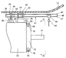
- FIG. 1 is a side view showing a rotating electrical machine disassembling apparatus according to the present embodiment together with a generator to be disassembled and assembled.
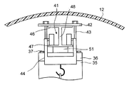
- FIG. 2 is a front view showing the rotary electric machine disassembling apparatus according to the present embodiment together with the generator to be disassembled and assembled, and is a view taken along the line II-II in FIG.
- the disassembling device 40 of the rotating electrical machine includes an I-shaped beam 41, a pressing plate 42, a fixing bolt 43, a trolley 44, and a chain block 45.
- the I-shaped beam 41 includes a pair of flanges 46 and 47 and a web 48 between the flanges 46 and 47, and extends in the horizontal direction above the frame 32.
- the length of the I-shaped beam 41 is, for example, about 2 m.
- the I-shaped beam 41 is positioned vertically above the rotary shaft 31 via the height adjusting squares 51 and 52 provided on the lid 36 and the hanging portion 39 of the terminal seat 35, respectively. Is placed.
- the two height adjusting square members 51 and 52 are different in height by the difference in height between the upper surface of the lid 36 of the terminal seat 35 and the upper surface of the hanging portion 39.
- a part of the I-shaped beam 41 protrudes outside the frame 32 from the bracket 33 closer to the coupling 22.
- the holding plate 42 is disposed on the I-shaped beam 41.
- a through hole is formed in the pressing plate 42, and the fixing bolt 43 extends vertically through the through hole.
- the fixing bolt 43 is screwed into the screw hole from which the bolt 37 that has fixed the lid 36 of the terminal seat 35 is removed.
- a fixing plate 53 is provided above the hanging portion 39.
- a fixing member 54 extending through the suspension hole 38 is fixed to the fixing plate 53 at two positions sandwiching the I-shaped beam 41.
- the fixing member 54 is a metal bar extending in a U shape, for example. In this way, by fixing the I-shaped beam 41 with the pressing plate 42 and the fixing plate 53 at a position where the pressing plate 42 and the I-shaped beam 41 extend in different directions, the horizontal movement of the I-shaped beam 41 is achieved. Is suppressed. For this reason, disassembly / assembly work is facilitated.
- the trolley 44 is attached so that it can move by rolling on the upper surface of the flange 47 on the lower side of the I-shaped beam 41.
- a chain block 45 that is a lifting machine is suspended from a trolley 44.
- the components of the disassembling apparatus 40 are moved into the nacelle 16. By transporting the components of the disassembling device 40, it is easier than transporting them in bulk.
- the wind power generation facility may be provided with a small winch capable of carrying an object of about 1 t. All the components of the disassembling apparatus of the present embodiment can be transported by such a small winch.
- the disassembling apparatus 40 is assembled in the state shown in FIGS. The disassembling / assembling work is performed using the disassembling apparatus 40 assembled in this way.
- the couplings 22 and 23 between the generator 30 and the speed increasing device 20 which is an external rotating body are disconnected. Thereby, a gap is formed between the coupling 22 on the generator 30 side and the speed increaser 20 side. Next, the coupling 22 on the generator 30 side is removed from the rotating shaft 31.
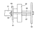
- FIG. 5 is a side view showing a state where a detaching jig is attached to the generator-side coupling in the present embodiment.
- FIG. 6 is a front view of the first jig used for removing the coupling in the present embodiment.
- FIG. 7 is a front view of a second jig used for removing the coupling in the present embodiment.
- the first jig 61 is a plate in which a penetrating portion 66 that is larger than the rotating shaft 31 and smaller than the coupling 22 is formed. This penetration part 66 is connected from the outer edge.
- the second jig 62 is a circular flat plate. In the first jig 61 and the second jig 62, holes 68 through which the bolts 67 pass are formed at corresponding positions.
- a reinforcing plate 69 is fixed to the outer periphery of the first jig 61. By fixing the reinforcing plate 69, it is possible to increase the strength while suppressing an increase in the weight of the first jig 61.
- 1st jig 61 and 2nd jig 62 are arranged so that coupling 22 may be inserted, and are combined using bolt 67 which penetrates hole 68. Further, a hydraulic jack 60 is disposed between the second jig 62 and the rotary shaft 31 that passes through the center of the coupling 22. The coupling 22 is removed from the rotating shaft 31 by extending the hydraulic jack 60 in the direction in which the rotating shaft 31 extends. Thus, even if the coupling 22 and the rotating shaft 31 are firmly fitted by shrink fitting, the coupling 22 can be detached from the rotating shaft 31. The outer periphery of the coupling 22 may be heated to loosen the fitting with the rotating shaft 31 and then removed, or the fitting may be loosened by heating and removed with the hydraulic jack 60.
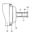
- FIG. 8 is a side view of a state in which a removal jig is attached to the external fan in the present embodiment.
- FIG. 9 is a front view of a third jig used for removing the external fan in the present embodiment.
- the external fan 25 is formed with a screw hole extending around the rotation shaft 31 in the same direction as the rotation shaft 31.
- the third jig 63 for removing the external fan 25 is a plate in which a hole 70 is formed at a position corresponding to the screw hole.
- the third jig 63 used for removing the external fan 25 is disposed so as to sandwich the hydraulic jack 60 between the end of the rotary shaft 31 and is connected to the external fan 25 by a bolt 71 screwed into the screw hole of the external fan 25. 25.
- the external fan 25 is removed from the rotating shaft 31 by extending the hydraulic jack 60 in the direction in which the rotating shaft 31 extends. Thus, even if the external fan 25 and the rotating shaft 31 are firmly fitted by shrink fitting, the external fan 25 can be removed from the rotating shaft 31.
- FIG. 10 is a side view taken along the line XX in FIG. 11 showing a state in which a removal jig is attached to the bracket in the present embodiment.
- FIG. 11 is a front view taken along arrow XI-XI in FIG.
- FIG. 12 is a perspective view of a fourth jig used for removing the bracket in the present embodiment.
- FIG. 13 is a perspective view of a fifth jig used for removing the bracket in the present embodiment.
- the fourth jig 64 used for removing the bracket 33 is formed with holes 72 penetrating through the two pairs of opposing faces of the rectangular parallelepiped.
- a fifth jig 65 used for removing the bracket 33 is one in which a head 75 is fixed to a wedge-shaped portion 74.
- the bracket 33 is provided with a block 79 in which a screw hole 78 in a direction perpendicular to the rotation shaft 31 is formed at every 90 degrees around the rotation shaft 31.
- the fourth jig 64 is fixed to the block 79 by a bolt 73 screwed into the screw hole 78.
- the wedge-shaped part 74 of the fifth jig 65 is fitted between the fourth jig 64 and the frame 32, and the head 75 is struck in the direction of the wedge-shaped part 74 with a hammer or the like.
- 33 is gradually removed from the frame 32.
- the bracket 33 can be removed from the frame 32 by performing the same operation for the four blocks 79.
- FIG. 14 is a side view of the present embodiment with the bracket removed.
- FIG. 15 is a front view of the present embodiment with the bracket removed.
- a swivel eye bolt 76 is attached to the screw holes 78 of the two blocks 79 on the upper side of the bracket 33 removed from the frame 32.
- the chain block 45 suspended from the trolley 44 is engaged with these swivel eye bolts 76.
- the bracket 33 is lifted by the chain block 45, and the trolley 44 is moved along the I-shaped beam 41 to the end of the end of the rotating shaft 31. Thereafter, the bracket 33 is lowered by the chain block 45 and the bracket 33 is temporarily placed on the floor of the nacelle 12.
- FIG. 16 is a side view in which a part of the frame is cut away, showing a state in which a removing jig is attached to the bearing in the present embodiment.
- the first jig 61 (see FIG. 6) and the second jig 62 (see FIG. 7) used for removing the coupling 22 are used.
- the first jig 61 and the second jig 62 have a hole 68 in addition to the hole 68 used when the coupling 22 is removed.
- the drawing bolts 77 are passed through these holes to fix the first jig 61 and the second jig 62.
- a hydraulic jack 60 is disposed between the second jig 62 and the rotating shaft 31.
- the bearing 29 can be removed from the rotating shaft 31 by extending the hydraulic jack 60 in the direction in which the rotating shaft 31 extends.
- the generator 30 can be disassembled.
- the disassembled generator 30 is assembled after the new bearing 29 is installed. After the new bearing 29 is installed, the bearing 29 is filled with grease. Further, a guide bolt for positioning is attached before the bracket 33 is attached.
- the bracket 33 is lifted by the chain block 45, the centers of the bearing 32 and the bracket 33 are aligned, and the trolley 44 is moved to return the bracket 33 to a predetermined position.
- the external fan 25 is fitted into the rotating shaft 31 in a heated state.
- the coupling 22 is heated and fitted into the rotating shaft 31.
- the rotating shaft 31 of the generator 30 and the shaft 24 of the speed increaser 20 are connected by connecting the coupling 22 on the generator 30 side and the coupling 23 on the speed increaser 20 side. In this way, the disassembly / assembly work is completed.
- each component constituting the disassembling apparatus is light in weight and thus easy to carry.
- the weight can be reduced as compared with the square bar having the same rigidity.
- the I-shaped beam 41 formed of a lightweight material such as aluminum the beam can be further reduced in weight. Since the components of the disassembling apparatus are lightweight, this is particularly effective when installation at a high position is required such as in a wind power generation facility.
- this disassembly device can be arranged if there is a gap about the height of the I-shaped beam 41 on the upper surface of the rotating electrical machine, it can also be used in a narrow place rather than providing legs on both sides of the rotating electrical machine. Can be used. Furthermore, by using the I-shaped beam 41, the trolley 44 can be disposed below the upper surface of the beam, so that disassembly / assembly work in a narrow space is facilitated.
- the inner surface of the nacelle is often shaped along the generator and gearbox. For this reason, the beam used as a rail may not be able to be bridged horizontally between the generator and the gearbox. Even in such a case, the disassembling apparatus of the present embodiment can be provided with a trolley that moves in the horizontal direction and a chain block that is a lifting device suspended from the trolley. For this reason, a heavy part like the bracket 33 can be easily transported.
Landscapes
- Engineering & Computer Science (AREA)
- Mechanical Engineering (AREA)
- Chemical & Material Sciences (AREA)
- Life Sciences & Earth Sciences (AREA)
- Sustainable Development (AREA)
- Sustainable Energy (AREA)
- Combustion & Propulsion (AREA)
- General Engineering & Computer Science (AREA)
- Power Engineering (AREA)
- Manufacturing & Machinery (AREA)
- Wind Motors (AREA)
- Motor Or Generator Frames (AREA)
- Manufacture Of Motors, Generators (AREA)
Abstract
Description
Claims (5)
- 下方に延びる少なくとも2本のねじ穴が形成されたフレームを備えた回転電機の分解装置において、
上側フランジと下側フランジとそれらの間のウェブとを備えて前記フレームの上方で水平方向に延びるI型梁と、
前記I型梁の上に配置された押さえ板と、
前記I型梁を挟んでそれぞれ前記押さえ板を貫通して延びて前記ねじ穴にねじ込まれた2本の固定ボルトと、
前記下側フランジの上面を転がって移動可能なトロリーと、
前記トロリーに吊り下げられた揚重機と、
を有することを特徴とする回転電機の分解装置。 - 前記I型梁はアルミニウム製であることを特徴とする請求の範囲1に記載の回転電機の分解装置。
- 前記フレームの上面には貫通する吊穴が形成された吊部が設けられていて、
前記I型梁が延びる方向の前記押さえ板と異なる位置で前記I型梁の上に配置された固定板と、
前記吊穴を通って延びて前記I型梁を挟む2か所で前記固定板に固定された固定材と、
を有することを特徴とする請求の範囲1または請求の範囲2に記載の回転電機の分解装置。 - 前記揚重機はチェーンブロックであることを特徴とする請求の範囲1ないし請求の範囲3のいずれか1項に記載の回転電機の分解装置。
- 下方に延びる少なくとも2本のねじ穴が形成されたフレームとそのフレームの内部に一部が収められた回転軸と備えた回転電機の分解方法において、
上側フランジと下側フランジとそれらの間のウェブとを備えるI型梁を前記フレームの上方で前記回転軸に平行に少なくとも一部が前記フレームから突出するように配置する工程と、
前記I型梁の上に押さえ板を配置する工程と、
2本の固定ボルトを前記押さえ板を貫通させて前記ねじ穴にねじ込む工程と、
トロリーを前記下側フランジの上面を転がって移動可能に配置する工程と、
前記トロリーに揚重機を吊り下げる工程と、
前記回転電機から部品を取り外す工程と、
前記部品を前記揚重機で吊り下げたまま前記トロリーを前記I型梁に沿って移動させる工程と、
を有することを特徴とする回転電機の分解方法。
Priority Applications (5)
| Application Number | Priority Date | Filing Date | Title |
|---|---|---|---|
| MX2011002576A MX2011002576A (es) | 2008-09-17 | 2008-09-17 | Aparato de desmantelamiento y metodo de desmantelamiento de maquina electrica giratoria. |
| PCT/JP2008/002559 WO2010032277A1 (ja) | 2008-09-17 | 2008-09-17 | 回転電機の分解装置および分解方法 |
| JP2010529511A JP5215403B2 (ja) | 2008-09-17 | 2008-09-17 | 回転電機の分解装置および分解方法 |
| CA2736549A CA2736549C (en) | 2008-09-17 | 2008-09-17 | Disassembly apparatus and disassembly method of rotating electric machine |
| US13/046,454 US8353100B2 (en) | 2008-09-17 | 2011-03-11 | Disassembly apparatus of rotating electric machine |
Applications Claiming Priority (1)
| Application Number | Priority Date | Filing Date | Title |
|---|---|---|---|
| PCT/JP2008/002559 WO2010032277A1 (ja) | 2008-09-17 | 2008-09-17 | 回転電機の分解装置および分解方法 |
Related Child Applications (1)
| Application Number | Title | Priority Date | Filing Date |
|---|---|---|---|
| US13/046,454 Continuation-In-Part US8353100B2 (en) | 2008-09-17 | 2011-03-11 | Disassembly apparatus of rotating electric machine |
Publications (1)
| Publication Number | Publication Date |
|---|---|
| WO2010032277A1 true WO2010032277A1 (ja) | 2010-03-25 |
Family
ID=42039131
Family Applications (1)
| Application Number | Title | Priority Date | Filing Date |
|---|---|---|---|
| PCT/JP2008/002559 Ceased WO2010032277A1 (ja) | 2008-09-17 | 2008-09-17 | 回転電機の分解装置および分解方法 |
Country Status (5)
| Country | Link |
|---|---|
| US (1) | US8353100B2 (ja) |
| JP (1) | JP5215403B2 (ja) |
| CA (1) | CA2736549C (ja) |
| MX (1) | MX2011002576A (ja) |
| WO (1) | WO2010032277A1 (ja) |
Cited By (4)
| Publication number | Priority date | Publication date | Assignee | Title |
|---|---|---|---|---|
| WO2012080537A1 (es) * | 2010-12-16 | 2012-06-21 | Gamesa Innovation & Technology S.L. | Metodo y dispositivo para la separacion de elementos de fijación |
| US20120228880A1 (en) * | 2009-11-20 | 2012-09-13 | Gamesa Innovation & Technology, S.L. | Wind turbine having internal transportation devices specification identification |
| JP2014003865A (ja) * | 2012-06-21 | 2014-01-09 | Hitachi Ltd | 回転電機の軸受交換方法及び軸受交換のための分解装置 |
| JP2017011942A (ja) * | 2015-06-25 | 2017-01-12 | 株式会社明電舎 | 回転電機の分解装置及び分解方法 |
Families Citing this family (19)
| Publication number | Priority date | Publication date | Assignee | Title |
|---|---|---|---|---|
| KR101038641B1 (ko) * | 2008-09-01 | 2011-06-03 | 두산중공업 주식회사 | 풍력터빈설비의 유지 보수 시스템 |
| WO2011099134A1 (ja) * | 2010-02-10 | 2011-08-18 | 三菱重工業株式会社 | 風力発電装置のロータヘッド内機器昇降方法 |
| EP2675047A1 (en) * | 2012-06-13 | 2013-12-18 | Alstom Technology Ltd | Method and device for extraction or introduction of a rotor from or into a stator of an electric machine |
| CN103107653B (zh) * | 2013-02-07 | 2015-02-04 | 上海博泽电机有限公司 | 一种小型电机的防损伤拆卸装置以及拆卸方法 |
| CN103406741B (zh) * | 2013-06-17 | 2015-09-30 | 宁波北仑宁润机械有限公司 | 导风罩装配工装 |
| JP6145026B2 (ja) * | 2013-10-30 | 2017-06-07 | 三菱日立パワーシステムズ株式会社 | 発電機の点検方法 |
| CN104124843B (zh) * | 2014-07-29 | 2016-05-18 | 江苏永钢集团有限公司 | 电机端盖拆卸装置 |
| CN105305735B (zh) * | 2015-10-23 | 2017-11-17 | 明阳智慧能源集团股份公司 | 一种垂直安装电机专用的拆装装置 |
| CN108661864B (zh) * | 2017-03-29 | 2022-03-22 | 通用电气公司 | 用于风轮机的齿轮箱组件的修理方法 |
| US10352305B2 (en) * | 2017-04-27 | 2019-07-16 | General Electric Company | System and method for removing or installing a main shaft of a wind turbine with a push/pull system configured at an end of the main shaft |
| US10436180B2 (en) * | 2017-04-27 | 2019-10-08 | General Electric Company | Apparatus and method for removing or installing a bearing unit in a wind turbine bedplate with an adjustable bearing support |
| US10422322B2 (en) * | 2017-04-27 | 2019-09-24 | General Electric Company | System and method for removing or installing a main shaft of a wind turbine with main shaft support elements |
| US10337503B2 (en) * | 2017-04-27 | 2019-07-02 | General Electric Company | System and method for removing or installing a main shaft of a wind turbine with rigging |
| US10781796B2 (en) * | 2017-07-11 | 2020-09-22 | General Electric Company | Clamping apparatus for positioning a main bearing of a wind turbine during an installation and/or repair procedure |
| CN108526844B (zh) * | 2018-06-11 | 2023-07-18 | 河南中烟工业有限责任公司 | 一种切丝机排链拆卸与安装工装 |
| CN110925140B (zh) * | 2019-12-12 | 2020-12-18 | 嘉兴市中法天线实业有限公司 | 一种自带升降保护的风力发电机 |
| CN113965035B (zh) * | 2021-10-26 | 2022-09-20 | 浙江九洲新能源科技有限公司 | 一种轮毂电机拆鼓盖工装 |
| EP4502369A1 (en) * | 2023-08-02 | 2025-02-05 | Siemens Gamesa Renewable Energy A/S | Handling apparatus |
| EP4502368A1 (en) * | 2023-08-02 | 2025-02-05 | Siemens Gamesa Renewable Energy A/S | Handling apparatus |
Citations (2)
| Publication number | Priority date | Publication date | Assignee | Title |
|---|---|---|---|---|
| JPH11335074A (ja) * | 1998-05-29 | 1999-12-07 | Toshiba Plant Kensetsu Co Ltd | 発電機の分解組立用治具 |
| JP2003165680A (ja) * | 2001-11-29 | 2003-06-10 | Fujitec Co Ltd | エレベータ電動機の吊持治具 |
Family Cites Families (10)
| Publication number | Priority date | Publication date | Assignee | Title |
|---|---|---|---|---|
| US3640658A (en) * | 1969-06-12 | 1972-02-08 | James H Price | Jobsite apparatus for horizontally pouring and vertical stacking of thin slabs |
| JPS565496Y2 (ja) * | 1975-09-11 | 1981-02-05 | ||
| US4381839A (en) * | 1981-03-02 | 1983-05-03 | Riggers Manufacturing Co. | Gantry having adjustable side supports |
| US4775313A (en) * | 1987-02-13 | 1988-10-04 | Diioia Michael A | Screed operating apparatus |
| US5332191A (en) * | 1992-10-26 | 1994-07-26 | Nolan Terry L | Apparatus for making concrete slabs |
| JPH10265181A (ja) * | 1997-03-19 | 1998-10-06 | Mitsubishi Denki Bill Techno Service Kk | 重量物吊り装置 |
| US7000460B1 (en) * | 2004-03-09 | 2006-02-21 | The United States Of America As Represented By The Secretary Of The Navy | Multiple engine test system |
| US7395594B2 (en) * | 2004-04-26 | 2008-07-08 | Siemens Power Generation, Inc. | Apparatus and method for the installation of a stator core into a power generator |
| US7467723B2 (en) * | 2005-03-18 | 2008-12-23 | Zaguroli Jr James | Electric motor driven traversing balancer hoist |
| US7484290B2 (en) * | 2006-02-22 | 2009-02-03 | General Electric Company | Methods and system to facilitate installation and removal of a generator rotor assembly |
-
2008
- 2008-09-17 MX MX2011002576A patent/MX2011002576A/es active IP Right Grant
- 2008-09-17 JP JP2010529511A patent/JP5215403B2/ja not_active Expired - Fee Related
- 2008-09-17 CA CA2736549A patent/CA2736549C/en active Active
- 2008-09-17 WO PCT/JP2008/002559 patent/WO2010032277A1/ja not_active Ceased
-
2011
- 2011-03-11 US US13/046,454 patent/US8353100B2/en active Active
Patent Citations (2)
| Publication number | Priority date | Publication date | Assignee | Title |
|---|---|---|---|---|
| JPH11335074A (ja) * | 1998-05-29 | 1999-12-07 | Toshiba Plant Kensetsu Co Ltd | 発電機の分解組立用治具 |
| JP2003165680A (ja) * | 2001-11-29 | 2003-06-10 | Fujitec Co Ltd | エレベータ電動機の吊持治具 |
Cited By (6)
| Publication number | Priority date | Publication date | Assignee | Title |
|---|---|---|---|---|
| US20120228880A1 (en) * | 2009-11-20 | 2012-09-13 | Gamesa Innovation & Technology, S.L. | Wind turbine having internal transportation devices specification identification |
| US9169824B2 (en) * | 2009-11-20 | 2015-10-27 | Gamesa Innovation & Technology, S.L. | Wind turbine having internal transportation devices specification identification |
| WO2012080537A1 (es) * | 2010-12-16 | 2012-06-21 | Gamesa Innovation & Technology S.L. | Metodo y dispositivo para la separacion de elementos de fijación |
| ES2384926A1 (es) * | 2010-12-16 | 2012-07-16 | Gamesa Innovation & Technology S.L. | Método y dispositivo para la separación de elementos de fijación. |
| JP2014003865A (ja) * | 2012-06-21 | 2014-01-09 | Hitachi Ltd | 回転電機の軸受交換方法及び軸受交換のための分解装置 |
| JP2017011942A (ja) * | 2015-06-25 | 2017-01-12 | 株式会社明電舎 | 回転電機の分解装置及び分解方法 |
Also Published As
| Publication number | Publication date |
|---|---|
| CA2736549C (en) | 2013-12-24 |
| US8353100B2 (en) | 2013-01-15 |
| CA2736549A1 (en) | 2010-03-25 |
| US20110162194A1 (en) | 2011-07-07 |
| MX2011002576A (es) | 2011-04-07 |
| JPWO2010032277A1 (ja) | 2012-02-02 |
| JP5215403B2 (ja) | 2013-06-19 |
Similar Documents
| Publication | Publication Date | Title |
|---|---|---|
| JP5215403B2 (ja) | 回転電機の分解装置および分解方法 | |
| KR200484342Y1 (ko) | 수직형 전동기의 커플링 분해 조립용 지그 | |
| JP2016508020A (ja) | 発電機のステータコアを分離する方法及び装置 | |
| KR101066577B1 (ko) | 대형 임펠러의 분해 및 조립용 지지장치 | |
| CN113914638A (zh) | 一种悬挑钢梁双轨幕墙吊装系统及幕墙板吊装方法 | |
| KR200444753Y1 (ko) | 발전기용 회전자의 단락환 분해 및 조립장치 | |
| KR101304012B1 (ko) | 전동기 회전자용 정비지그 | |
| JP6145026B2 (ja) | 発電機の点検方法 | |
| CN103508332B (zh) | 塔机及其转换基座 | |
| US20130340256A1 (en) | Bearing replacement method and tools for rotating machine | |
| EP2617988B1 (en) | Manual lifting tool for wind turbines | |
| US20180313334A1 (en) | Hoistable platform assembly within a nacelle of a wind turbine | |
| CN203545527U (zh) | 塔机及其转换基座 | |
| JP2010236226A (ja) | 建築用シャッター装置およびその取付け方法 | |
| KR100422786B1 (ko) | 선재 사상압연기용 감속기 수리작업대 | |
| KR200482885Y1 (ko) | 수직형 모터의 부품 분해,조립 작업용 리프팅 거치대 | |
| US12473179B2 (en) | Base for supporting a portable crane and a method for removing a main bearing of a wind turbine | |
| CN205277707U (zh) | 风力发电机组内的升降机支撑结构及风力发电机组的塔架 | |
| CN220299395U (zh) | 一种轨道车用设备移动工具 | |
| KR101444135B1 (ko) | 장갑차용 인양장치 | |
| CN222147370U (zh) | 一种永磁发电机定子转子相对位置保持调节工装 | |
| CN219485551U (zh) | 一种用于拆装电机安装盘的专用工具 | |
| CN121134570A (zh) | 一种用于环行桥式起重机吊装的吊装工具及吊装方法 | |
| KR102029259B1 (ko) | 풍력발전기용 요 시스템의 슬라이딩 패드 교체시스템 및 교체방법 |
Legal Events
| Date | Code | Title | Description |
|---|---|---|---|
| 121 | Ep: the epo has been informed by wipo that ep was designated in this application |
Ref document number: 08808500 Country of ref document: EP Kind code of ref document: A1 |
|
| WWE | Wipo information: entry into national phase |
Ref document number: 2010529511 Country of ref document: JP |
|
| WWE | Wipo information: entry into national phase |
Ref document number: 2736549 Country of ref document: CA Ref document number: MX/A/2011/002576 Country of ref document: MX |
|
| NENP | Non-entry into the national phase |
Ref country code: DE |
|
| 122 | Ep: pct application non-entry in european phase |
Ref document number: 08808500 Country of ref document: EP Kind code of ref document: A1 |