WO2010029804A1 - Nmrプローブ - Google Patents
Nmrプローブ Download PDFInfo
- Publication number
- WO2010029804A1 WO2010029804A1 PCT/JP2009/061838 JP2009061838W WO2010029804A1 WO 2010029804 A1 WO2010029804 A1 WO 2010029804A1 JP 2009061838 W JP2009061838 W JP 2009061838W WO 2010029804 A1 WO2010029804 A1 WO 2010029804A1
- Authority
- WO
- WIPO (PCT)
- Prior art keywords
- probe coil
- intermediate tap
- winding portion
- nmr
- magnetic field
- Prior art date
- Legal status (The legal status is an assumption and is not a legal conclusion. Google has not performed a legal analysis and makes no representation as to the accuracy of the status listed.)
- Ceased
Links
Images







Classifications
-
- G—PHYSICS
- G01—MEASURING; TESTING
- G01R—MEASURING ELECTRIC VARIABLES; MEASURING MAGNETIC VARIABLES
- G01R33/00—Arrangements or instruments for measuring magnetic variables
- G01R33/20—Arrangements or instruments for measuring magnetic variables involving magnetic resonance
- G01R33/28—Details of apparatus provided for in groups G01R33/44 - G01R33/64
- G01R33/32—Excitation or detection systems, e.g. using radio frequency signals
- G01R33/34—Constructional details, e.g. resonators, specially adapted to MR
- G01R33/34046—Volume type coils, e.g. bird-cage coils; Quadrature bird-cage coils; Circularly polarised coils
-
- G—PHYSICS
- G01—MEASURING; TESTING
- G01R—MEASURING ELECTRIC VARIABLES; MEASURING MAGNETIC VARIABLES
- G01R33/00—Arrangements or instruments for measuring magnetic variables
- G01R33/20—Arrangements or instruments for measuring magnetic variables involving magnetic resonance
- G01R33/28—Details of apparatus provided for in groups G01R33/44 - G01R33/64
- G01R33/32—Excitation or detection systems, e.g. using radio frequency signals
- G01R33/34—Constructional details, e.g. resonators, specially adapted to MR
- G01R33/34046—Volume type coils, e.g. bird-cage coils; Quadrature bird-cage coils; Circularly polarised coils
- G01R33/34053—Solenoid coils; Toroidal coils
-
- G—PHYSICS
- G01—MEASURING; TESTING
- G01R—MEASURING ELECTRIC VARIABLES; MEASURING MAGNETIC VARIABLES
- G01R33/00—Arrangements or instruments for measuring magnetic variables
- G01R33/20—Arrangements or instruments for measuring magnetic variables involving magnetic resonance
- G01R33/28—Details of apparatus provided for in groups G01R33/44 - G01R33/64
- G01R33/32—Excitation or detection systems, e.g. using radio frequency signals
- G01R33/34—Constructional details, e.g. resonators, specially adapted to MR
- G01R33/34007—Manufacture of RF coils, e.g. using printed circuit board technology; additional hardware for providing mechanical support to the RF coil assembly or to part thereof, e.g. a support for moving the coil assembly relative to the remainder of the MR system
-
- G—PHYSICS
- G01—MEASURING; TESTING
- G01R—MEASURING ELECTRIC VARIABLES; MEASURING MAGNETIC VARIABLES
- G01R33/00—Arrangements or instruments for measuring magnetic variables
- G01R33/20—Arrangements or instruments for measuring magnetic variables involving magnetic resonance
- G01R33/28—Details of apparatus provided for in groups G01R33/44 - G01R33/64
- G01R33/32—Excitation or detection systems, e.g. using radio frequency signals
- G01R33/34—Constructional details, e.g. resonators, specially adapted to MR
- G01R33/34092—RF coils specially adapted for NMR spectrometers
-
- G—PHYSICS
- G01—MEASURING; TESTING
- G01R—MEASURING ELECTRIC VARIABLES; MEASURING MAGNETIC VARIABLES
- G01R33/00—Arrangements or instruments for measuring magnetic variables
- G01R33/20—Arrangements or instruments for measuring magnetic variables involving magnetic resonance
- G01R33/44—Arrangements or instruments for measuring magnetic variables involving magnetic resonance using nuclear magnetic resonance [NMR]
- G01R33/48—NMR imaging systems
- G01R33/54—Signal processing systems, e.g. using pulse sequences ; Generation or control of pulse sequences; Operator console
- G01R33/56—Image enhancement or correction, e.g. subtraction or averaging techniques, e.g. improvement of signal-to-noise ratio and resolution
- G01R33/565—Correction of image distortions, e.g. due to magnetic field inhomogeneities
- G01R33/56536—Correction of image distortions, e.g. due to magnetic field inhomogeneities due to magnetic susceptibility variations
Definitions
- the present invention relates to a solenoid type probe coil for detecting an NMR signal of a sample.
- Nuclear magnetic resonance (NMR) spectroscopy is used for molecular structure analysis of proteins and is used for research such as life science and drug discovery. And in order to analyze the structure of a more complicated molecule
- the direction of the high-frequency magnetic field generated by the probe coil needs to be orthogonal to the direction of the static magnetic field generated by the superconducting magnet. Therefore, in the case of the NMR apparatus for solution in which the sample tube is inserted from the vertical direction, it is impossible to wind a solenoid type probe coil around the sample tube inserted into the bore in the conventional solenoid type superconducting magnet. Therefore, an NMR apparatus using a split type superconducting magnet has been proposed. A probe is inserted from a horizontal bore opened in the central axis of the split magnet, and a sample tube is inserted from a vertical bore opened in the gap portion of the split magnet. Thus, a solenoid type probe coil can be installed around the sample tube, and an NMR signal can be measured.
- the resonance frequency of the probe coil must be tuned to the resonance frequency of the nuclide to be detected, and at the same time, the impedance at the resonance frequency must be matched to a specific impedance such as 50 ⁇ . Since the signal intensity of the NMR signal depends on the Q value of the resonance circuit, a high Q value is required for high sensitivity. In general, the signal intensity increases as the number of turns of the probe coil increases. However, when the number of turns increases, the self-resonance frequency of the probe coil decreases and the resonance frequency cannot be tuned.
- Patent Document 1 discloses a method in which a signal line (hereinafter referred to as an intermediate tap line) is connected to a substantially midpoint of a probe coil, and a variable capacitance trimmer capacitor is connected to both sides of the probe coil. Proposed. As a result, tuning matching can be realized without lowering the Q value, and resonance can be achieved without reducing the number of turns even at a high frequency such as 600 MHz.
- Patent Documents 2 and 3 propose a method of reducing the magnetic susceptibility as a whole by combining a paramagnetic material and a diamagnetic material at an appropriate ratio and suppressing an error magnetic field.
- the magnetic susceptibility cannot be completely canceled due to the manufacturing accuracy of the material, the variation in the magnetic susceptibility of the material, and the change in the magnetic susceptibility during processing of the material.
- the magnetic susceptibility of the probe coil material can be reduced to 1% of the magnetic susceptibility of copper, an error magnetic field of several ppb is generated in the sample space. In that case, the error magnetic field is canceled using the magnetic field correction coil.
- the magnitude and shape of the correctable magnetic field are limited, it is necessary to make the generated error magnetic field as small as possible.
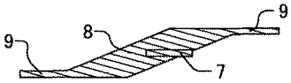
- FIGS. 2A and 2B show diagrams in which an intermediate tap wire is connected to a flat two-turn coil.
- the intermediate tap lines are connected in this way, the volume of the material is increased at the overlapping connection.
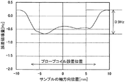
- an error magnetic field as shown in FIG. 3 appears in the sample space.
- the vertical axis in FIG. 3 is a value obtained by converting an error magnetic field into a frequency when a 14T static magnetic field is applied, that is, when the resonance frequency is 600 MHz.
- the error magnetic field is large at the midpoint of the probe coil connected to the intermediate tap wire. Further, since the connection of the intermediate tap wire is usually performed by welding or the like, it is conceivable that the magnetic susceptibility of the material changes due to the application of heat or force, and a larger error magnetic field is generated.
- An object of the present invention is to provide a probe capable of suppressing an increase in error magnetic field caused by a connection portion of an intermediate tap wire and preventing a decrease in spectral resolution in a flat plate-like solenoid probe coil for NMR measurement having an intermediate tap wire. To provide a coil.
- a flat-plate solenoid probe coil having an intermediate tap wire is formed from a one-plane conductor material, which is a combination of a diamagnetic material and a paramagnetic material.
- the probe coil of the present invention has a winding portion, two lead wires drawn from both ends of the winding portion, and an intermediate tap wire drawn from between the two lead wires.
- it is made of a flat conductive material
- the winding portion, the lead wire, and the intermediate tap wire are made of a single flat conductive material.
- the NMR apparatus of the present invention is an NMR apparatus having a superconducting magnet and a probe coil for detecting an NMR signal from a sample placed in a static magnetic field formed by the superconducting magnet.
- the probe coil is made of a flat conductor material, and is drawn from the winding portion, the two lead wires drawn from both ends of the winding portion, and the winding portion between the two lead wires.
- the winding portion, the lead wire, and the intermediate tap wire are formed of a planar conductive material.
- the intermediate tap line is connected to a signal line for transmitting an NMR signal by bending the one-plane conductive material.
- the drawing position of the intermediate tap line does not need to be exactly the midpoint of the probe coil, but it is desirable to draw it so that the distance to the signal line is the shortest in order to suppress loss due to resistance. Further, when the winding interval is shortened at the bent portion of the intermediate tap line, a cut is made at the base of the intermediate tap wire so that the winding interval does not change.
- the step of connecting the intermediate tap wire of the solenoid type probe coil is not necessary. Therefore, an increase in error magnetic field due to the connecting portion of the intermediate tap line can be suppressed, and the spectral resolution of the NMR signal can be improved.
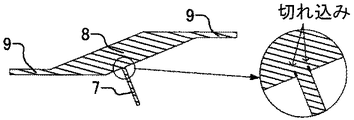
- FIG. 3 is a three-dimensional view of the probe coil according to the first embodiment.
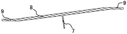
- FIG. 1B is a development view of the probe coil of FIG. 1A.
- FIG. 2B is a development view of the probe coil of FIG. 2A.
- the graph which shows the error magnetic field distribution of the conventional probe coil.
- the block diagram of the NMR apparatus using a split type superconducting magnet. The circuit diagram when using the probe coil which has an intermediate tap wire. Sectional drawing of probe coil material. 6 is a graph showing an error magnetic field distribution of the probe coil of Example 1.
- FIG. 3 is a three-dimensional view of the probe coil of Example 1 when the number of turns is 4 turns.
- FIG. 8B is a development view of the probe coil of FIG. 8A.
- 3 is a three-dimensional view of a probe coil of Example 2.
- FIG. FIG. 9B is a development view of the probe coil of FIG. 9A.
- FIG. 4 is a configuration diagram of an NMR apparatus using a split type superconducting magnet.
- the superconducting coils 1 and 1 are arranged opposite to each other on a common central axis, and a uniform static magnetic field is generated at the center of the bore where the axis of the horizontal bore 3 and the axis of the vertical bore 4 intersect.
- the probe 2 is inserted from the horizontal bore 3 and the sample tube 5 is inserted from the vertical bore.
- the enlarged view of FIG. 4 shows a layout near the tip of the probe 2.
- a solenoid type probe coil 6 installed in the probe 2 is disposed at the center of the bore, and a sample tube 5 is inserted therein. As shown in FIG.
- the intermediate tap line 7 connected to substantially the middle point of the probe coil is connected to a signal line 11, and both ends of the probe coil are connected to a variable trimmer capacitor 10. The other ends of these capacitors are all grounded.
- the material used for the probe coil is required to have a low resistance in order to pass a high-frequency current with a low loss, and to have a low magnetic susceptibility so as not to disturb the magnetic field uniformity of the sample space. Therefore, in order to cancel the diamagnetic magnetization, materials such as gold, silver, and copper with high conductivity are placed outside, and paramagnetic materials such as aluminum, tantalum, niobium, and platinum are placed inside.
- the arranged laminated material is used as a material for the probe coil.
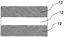
- FIG. 6 shows a cross-sectional view of the probe coil material when the diamagnetic material-paramagnetic material-diamagnetic material are laminated in three layers.
- a probe coil having an intermediate tap line is formed from a conductor material having a single planar shape, thereby further reducing the error magnetic field.
- FIG. 1A is a diagram for explaining this embodiment.
- a flat solenoid probe coil having an intermediate tap wire 7 is formed of a one-plane conductive material.
- the intermediate tap line 7 is drawn out at a substantially right angle with respect to the winding portion 8, and is bent and connected to the signal line.
- the error magnetic field distribution in the sample space of this example is calculated as shown in FIG. It can be seen that the error magnetic field is reduced to about two-thirds compared to the conventional structure in which the intermediate tap line is connected.
- the bent portion protrudes by the thickness of the material.
- the winding interval is sufficiently large relative to the thickness of the material, but if the material thickness and the winding interval are the same, there is a risk that the bulge will touch the adjacent winding and cause a short circuit. is there.
- FIG. 1B by providing a notch at the base of the intermediate tap line 7, it is possible to prevent the winding interval from changing even if it is bent.
- FIGS. 8A and 8B show an embodiment in which the number of turns is 4 turns.
- the intermediate tap wire 7 is drawn at a substantially right angle with respect to the winding portion 8 on the development view.
- the development view of FIG. It is also possible to pull it out almost in parallel.
- a three-dimensional view of the probe coil in this case is shown in FIG. 9A.
- the error magnetic field can be reduced as compared with the conventional structure.
- the position and angle at which the intermediate tap line 7 is drawn out are not limited to the first and second embodiments, and can be arbitrarily determined. For example, it is possible to draw the intermediate tap line 7 from the direction opposite to the lead line 9, and the drawing angle may be changed midway. However, since the loss due to the resistance increases as the distance from the drawing position of the intermediate tap line to the signal line increases, it is desirable that the distance from the signal line be minimized.
Landscapes
- Physics & Mathematics (AREA)
- Condensed Matter Physics & Semiconductors (AREA)
- General Physics & Mathematics (AREA)
- Magnetic Resonance Imaging Apparatus (AREA)
Abstract
高感度,分解能のNMR装置を提供する本発明の特徴は、巻線部と、該巻線部の両端部より引き出された2本の引き出し線と、該2本の引き出し線の間より引き出された中間タップ線を有する、平板状の導電体材料よりなるソレノイド型プローブコイルであって、前記巻線部と、前記引き出し線と、前記中間タップ線が一平面形状の導電体材料より作成されるものをプローブコイルとして使用することにある。導電体材料は、反磁性材料と常磁性材料を組み合わせた、一平面形状を有するものである。
Description
本発明は、サンプルのNMR信号を検出するための、ソレノイド型プローブコイルに関する。
核磁気共鳴(NMR)分光法は、タンパク質の分子構造解析などに用いられ、生命科学や創薬などの研究に活用されている。そして、より複雑な分子の構造を解析するために、NMR装置の高感度化・高分解能化が求められている。
高感度化を図るためには、超電導マグネットを用いて、サンプルに印加する静磁場の強度を高くする必要がある。また、高感度化のためのもう一つの方法として、NMR信号を検出するためのプローブコイルに、鞍型コイルと比べて検出効率の高いソレノイド型コイルを用いる方法がある。
NMR信号を測定するためには、プローブコイルによる高周波磁場の方向が超電導マグネットによる静磁場の方向と直交している必要がある。そのため、鉛直方向からサンプル管を挿入する溶液用NMR装置の場合、従来のソレノイド型超電導マグネットでは、ボアに挿入したサンプル管の周りにソレノイド型のプローブコイルを巻くことは不可能である。そこで、スプリット型の超電導マグネットを用いたNMR装置が提案されている。スプリットマグネットの中心軸に開けられた水平方向のボアからプローブを挿入し、スプリットマグネットのギャップ部に開けられた垂直方向のボアからサンプル管を挿入する。これによって、ソレノイド型プローブコイルをサンプル管の周りに設置することができ、NMR信号を測定することが可能となる。
さらに、NMR信号を測定するためには、プローブコイルの共振特性の同調と整合をとる必要がある。すなわち、プローブコイルの共振周波数を、検出する核種の共鳴周波数に同調し、同時に共振周波数におけるインピーダンスを50Ωなど特定のインピーダンスに整合しなければならない。NMR信号の信号強度は共振回路のQ値に依存するため、高感度化のためには高いQ値が要求される。また一般にプローブコイルのターン数が多いほど信号強度は増大するが、ターン数が多くなるとプローブコイルの自己共振周波数が低下し、共鳴周波数に同調できなくなる。
特許文献1には、プローブコイルのほぼ中点に信号線と接続するための線(以下、中間タップ線と表記する)を接続し、プローブコイルの両側に容量可変のトリマコンデンサを接続する方法が提案されている。それによりQ値を低下させることなく同調整合が実現でき、また600MHzなどの高い周波数でもターン数を減らすことなく、共振をとることが可能となる。
一方、NMR信号のスペクトル分解能を高めるためには、サンプルが設置される空間の磁場均一度を向上させる必要がある。サンプル空間における磁場は、周囲に用いる部品から生じる磁場によって乱される。以降、周囲の部品から生じる磁場を誤差磁場と呼ぶ。誤差磁場を抑えるためには、可能な限り磁化率の小さい材料を使用することが必要である。中でもNMR信号を検出するためのプローブコイルは、サンプル空間から最も近い位置に設置されるため、それによる誤差磁場の低減が必要となる。
特許文献2,3などには、常磁性材料と反磁性材料を適当な比率で合わせることにより全体としての磁化率を低減し、誤差磁場を抑制する方法が提案されている。
常磁性材料と反磁性材料を適当な比率で合わせることにより、全体としての磁化率をゼロに近づけることは可能である。しかし、材料の製作精度,材料の磁化率のばらつき,材料の加工における磁化率の変化などにより、磁化率を完全に相殺することはできない。例えば、プローブコイル材料の磁化率を銅の磁化率の1%まで低減できたとしても、サンプル空間では数ppbの誤差磁場が発生する。その場合、磁場補正コイルを用いて誤差磁場をキャンセルするが、補正可能な磁場の大きさや形状は限られているため、発生する誤差磁場を可能な限り小さくすることが必要である。
高感度なNMR信号測定のためには、プローブコイルに中間タップ線を接続する方法が有効である。図2A,2Bに一例として、平板状の2ターンコイルに中間タップ線を接続した図を示す。このように中間タップ線を接続すると、重ねて接続した部分で材料の体積が大きくなる。例えば、このときのプローブコイル材料の磁化率が銅の磁化率の1%であったとして誤差磁場分布を計算すると、サンプル空間には図3に示すような誤差磁場が現れる。図3の縦軸は、14Tの静磁場が印加されているとき、すなわち共鳴周波数が600MHzのときの誤差磁場を周波数に換算した値である。中間タップ線を接続したプローブコイル中点において、誤差磁場が大きいことがわかる。また中間タップ線の接続は、通常溶接などで行うため、熱や力が加わることにより材料の磁化率が変化し、これよりも大きな誤差磁場が発生することも考えられる。
本発明の目的は、中間タップ線を有する平板状のNMR計測用ソレノイド型プローブコイルにおいて、中間タップ線の接続部に起因する誤差磁場増大を抑制し、スペクトル分解能の低下を防ぐことの可能なプローブコイルを提供することにある。
上記課題を解決するための本発明は、反磁性材料と常磁性材料を組み合わせた、一平面形状の導電体材料より中間タップ線を有する平板状のソレノイド型プローブコイルを形成したことにある。
本発明のプローブコイルは、巻線部と、該巻線部の両端部より引き出された2本の引き出し線と、該2本の引き出し線の間より引き出された中間タップ線を有する。特に、平板状の導電体材料よりなり、前記巻線部と、前記引き出し線と、前記中間タップ線が一平面形状の導電体材料より形成されることを特徴とする。また、本発明のNMR装置は、超電導マグネットと、超電導マグネットによって形成される静磁場中に配置されたサンプルからNMR信号を検出するプローブコイルとを有するNMR装置である。前記プローブコイルは平板状の導電体材料よりなり、巻線部と、該巻線部の両端部より引き出された二本の引き出し線と、該二本の引き出し線の間で巻線部より引き出された中間タップ線とを有し、前記巻線部と、前記引き出し線と、前記中間タップ線とが平面形状の導電体材料より形成されていることを特徴とする。
前記中間タップ線は、前記一平面形状の導電体材料を折り曲げて、NMR信号を伝送するための信号線と接続する。中間タップ線の引き出し位置は、厳密にプローブコイルの中点である必要はないが、抵抗による損失を抑えるために、信号線までの距離が最短になるように引き出すことが望ましい。また中間タップ線を折り曲げた部分で、巻線間隔が短くなってしまうような場合には、中間タップ線の根元に切れ込みを入れて、巻線間隔が変わらないようにする。
本発明によれば、ソレノイド型プローブコイルの中間タップ線接続の工程が不要となる。それにより、中間タップ線の接続部分に起因する誤差磁場増大を抑制し、NMR信号のスペクトル分解能を向上させることができる。
本発明の他の目的、特徴及び利点は添付図面に関する以下の本発明の実施例の記載から明らかになるであろう。
本発明の他の目的、特徴及び利点は添付図面に関する以下の本発明の実施例の記載から明らかになるであろう。
図4は、スプリット型超電導マグネットを用いたNMR装置の構成図である。共通の中心軸上に超電導コイル1,1が対向して配置され、水平ボア3の軸と垂直ボア4の軸が交わるボア中心に均一な静磁場が生成される。プローブ2は水平ボア3から挿入され、サンプル管5は垂直ボアから挿入される。図4の拡大図はプローブ2の先端付近の配置図を示している。プローブ2内に設置されたソレノイド型プローブコイル6がボア中心に配置され、その中にサンプル管5が挿入される。図5に示すように、プローブコイルのほぼ中点に接続された中間タップ線7は信号線11と接続され、プローブコイルの両端は容量可変のトリマコンデンサ10と接続される。そして、それらコンデンサの他端は、いずれもグラウンドに接地される。
上記記載は実施例についてなされたが、本発明はそれに限らず、本発明の精神と添付の請求の範囲の範囲内で種々の変更および修正をすることができることは当業者に明らかである。
上記記載は実施例についてなされたが、本発明はそれに限らず、本発明の精神と添付の請求の範囲の範囲内で種々の変更および修正をすることができることは当業者に明らかである。
プローブコイルに用いる材料に求められるのは、高周波電流を低損失で流すために低抵抗であること、またサンプル空間の磁場均一度を乱さないために低磁化率であることである。そのため、導電率の高い金,銀,銅などの材料を高周波電流が流れる外側に配置し、それらの反磁性磁化をキャンセルするために、アルミニウム,タンタル,ニオブ,白金などの常磁性材料を内側に配置した積層材料をプローブコイルの材料として用いる。例えば、反磁性材料-常磁性材料-反磁性材料と3層に積層した場合のプローブコイル材料の断面図は、図6のようになる。
以上のように、反磁性材料と常磁性材料を組み合わせたとしても、作製した材料の磁化率を完全にゼロにすることはできず、プローブコイルによるある程度の誤差磁場発生は避けられない。そこで本発明では、材料の磁化率を抑える従来の方法に加えて、中間タップ線を有するプローブコイルを一平面形状の導電体材料より形成することにより、さらなる誤差磁場の低減を図る。以下では、本発明の実施形態について図面を用いて説明する。
図1Aは、本実施例を説明する図である。中間タップ線7を有する平板状のソレノイド型プローブコイルを一平面形状の導電体材料より形成している。図1Bの展開図において、中間タップ線7は、巻線部8に対してほぼ直角に引き出され、それを折り曲げて信号線に接続される。図3の計算と同様に、材料の磁化率が銅の磁化率の1%であったとして、本実施例のサンプル空間における誤差磁場分布を計算すると、図7のようになる。中間タップ線を接続した従来の構造と比較して、誤差磁場が約3分の2に低減していることがわかる。
本実施例のように中間タップ線7を折り曲げた場合、折り曲げた部分において、材料の厚さの分だけ出っ張ってしまう。材料の厚さに対して巻線間隔が十分に大きい場合は問題ないが、材料の厚さと巻線間隔が同程度の場合、その出っ張りが隣の巻線に接触し、ショートしてしまう恐れがある。そのような場合、図1Bの拡大図に示したように中間タップ線7の根元に切れ込みを設けることで、折り曲げても巻線間隔が変わらないようにすることができる。
図1A,1Bは、巻数が2ターンの場合であるが、目的の周波数で共振をとることができれば、巻数は何ターンでも実施可能である。その一例として、巻数が4ターンのときの実施例を図8A,8Bに示す。
実施例1では、展開図上で中間タップ線7を巻線部8に対してほぼ直角に引き出したが、図9Bの展開図に示すように、中間タップ線7を巻線部8に対してほぼ平行に引き出すことも可能である。この場合のプローブコイルの立体図を図9Aに示す。このときも実施例1と同じように、従来の構造と比べて誤差磁場を低減することができる。
以上、2つの実施例を説明したが、中間タップ線7を引き出す位置や角度は、実施例1,2に限らず、任意に決めることができる。例えば中間タップ線7を引き出し線9と逆の方向から引き出すことも可能であり、引き出す角度を途中で変更しても構わない。ただし、中間タップ線の引き出し位置から信号線までの距離が長くなると、抵抗による損失が大きくなるため、信号線との距離が最短になるように引き出すことが望ましい。
1 超電導コイル
2 プローブ
3 水平ボア
4 垂直ボア
5 サンプル管
6 ソレノイド型プローブコイル
7 プローブコイルの中間タップ線
8 プローブコイルの巻線部
9 プローブコイルの引き出し線
10 トリマコンデンサ
11 信号線
12 反磁性材料
13 常磁性材料
2 プローブ
3 水平ボア
4 垂直ボア
5 サンプル管
6 ソレノイド型プローブコイル
7 プローブコイルの中間タップ線
8 プローブコイルの巻線部
9 プローブコイルの引き出し線
10 トリマコンデンサ
11 信号線
12 反磁性材料
13 常磁性材料
Claims (10)
- 超電導マグネットと、超電導マグネットによって形成される静磁場中に配置されたサンプルからNMR信号を検出するプローブコイルとを有するNMR装置であって、
前記プローブコイルは平板状の導電体材料よりなり、巻線部と、該巻線部の両端部より引き出された二本の引き出し線と、該二本の引き出し線の間で巻線部より引き出された中間タップ線とを有し、
前記巻線部と、前記引き出し線と、前記中間タップ線とが平面形状の導電体材料より形成されていることを特徴とするNMR装置。 - 請求項1に記載されたNMR装置であって、前記中間タップ線は、前記NMR信号を伝送するための信号線と接続されていることを特徴とするNMR装置。
- 請求項1に記載されたNMR装置であって、前記中間タップ線と巻線部との接続部の巻線部側に切れ込み部を有することを特徴とするNMR装置。
- 請求項1に記載されたNMR装置であって、前記二本の引き出し線のいずれかと接続され、かつグラウンドに接地されたコンデンサを有することを特徴とするNMR装置。
- 請求項1に記載されたNMR装置であって、前記導電体材料は、常磁性材料と反磁性材料とを組み合わせた積層材料よりなる事を特徴とするNMR装置。
- 静磁場中に配置されたサンプルより得られるNMR信号を検出するためのプローブコイルであって、
前記プローブコイルは巻線部と、該巻線部の両端にそれぞれ設けられた引き出し線と、前記巻き線部の前記引き出し線の間に設けられた中間タップ線を有し、
前記プローブコイルは一平面形状の導電体材料を曲げて形成されていることを特徴とするプローブコイル。 - 請求項6に記載されたプローブコイルであって、前記中間タップ線は、前記NMR信号を転送する信号線と接続されることを特徴とするプローブコイル。
- 請求項6に記載されたプローブコイルであって、前記中間タップ線は前記巻き線部に対し折り曲げられており、前記巻き線部には、前記中間タップ線との接続部に切れ込みが設けられていることを特徴とするプローブコイル。
- 請求項6に記載されたプローブコイルであって、前記引き出し線はコンデンサを介して接地されることを特徴とするプローブコイル。
- 請求項6に記載されたプローブコイルであって、前記導電体材料は、常磁性材料及び反磁性材料を組み合わせ構成されていることを特徴とするプローブコイル。
Applications Claiming Priority (2)
| Application Number | Priority Date | Filing Date | Title |
|---|---|---|---|
| JP2008234156A JP2010066180A (ja) | 2008-09-12 | 2008-09-12 | Nmrプローブ |
| JP2008-234156 | 2008-09-12 |
Publications (1)
| Publication Number | Publication Date |
|---|---|
| WO2010029804A1 true WO2010029804A1 (ja) | 2010-03-18 |
Family
ID=42005066
Family Applications (1)
| Application Number | Title | Priority Date | Filing Date |
|---|---|---|---|
| PCT/JP2009/061838 Ceased WO2010029804A1 (ja) | 2008-09-12 | 2009-06-29 | Nmrプローブ |
Country Status (2)
| Country | Link |
|---|---|
| JP (1) | JP2010066180A (ja) |
| WO (1) | WO2010029804A1 (ja) |
Cited By (1)
| Publication number | Priority date | Publication date | Assignee | Title |
|---|---|---|---|---|
| US10416260B2 (en) | 2011-10-17 | 2019-09-17 | Koninklijke Philips N.V. | Magnetic field probe for MRI with a fluoroelastomer or a solution of a fluorine-containing compound |
Citations (3)
| Publication number | Priority date | Publication date | Assignee | Title |
|---|---|---|---|---|
| JP2003011268A (ja) * | 2001-06-28 | 2003-01-15 | Jeol Ltd | 金属積層体及び該金属積層体で作られたnmr用コイル |
| JP2004325439A (ja) * | 2003-04-11 | 2004-11-18 | Jeol Ltd | Nmr測定方法およびnmr装置 |
| JP2008122141A (ja) * | 2006-11-09 | 2008-05-29 | Hitachi Ltd | Nmr計測用プローブ、およびそれを用いたnmr装置 |
-
2008
- 2008-09-12 JP JP2008234156A patent/JP2010066180A/ja active Pending
-
2009
- 2009-06-29 WO PCT/JP2009/061838 patent/WO2010029804A1/ja not_active Ceased
Patent Citations (3)
| Publication number | Priority date | Publication date | Assignee | Title |
|---|---|---|---|---|
| JP2003011268A (ja) * | 2001-06-28 | 2003-01-15 | Jeol Ltd | 金属積層体及び該金属積層体で作られたnmr用コイル |
| JP2004325439A (ja) * | 2003-04-11 | 2004-11-18 | Jeol Ltd | Nmr測定方法およびnmr装置 |
| JP2008122141A (ja) * | 2006-11-09 | 2008-05-29 | Hitachi Ltd | Nmr計測用プローブ、およびそれを用いたnmr装置 |
Cited By (1)
| Publication number | Priority date | Publication date | Assignee | Title |
|---|---|---|---|---|
| US10416260B2 (en) | 2011-10-17 | 2019-09-17 | Koninklijke Philips N.V. | Magnetic field probe for MRI with a fluoroelastomer or a solution of a fluorine-containing compound |
Also Published As
| Publication number | Publication date |
|---|---|
| JP2010066180A (ja) | 2010-03-25 |
Similar Documents
| Publication | Publication Date | Title |
|---|---|---|
| US8115488B2 (en) | Tuning low-inductance coils at low frequencies | |
| US7405567B2 (en) | Tuning low-inductance coils at low frequencies | |
| JP4768627B2 (ja) | 超高磁場(shf)mri用のrfコイル | |
| JP3770799B2 (ja) | 多周波数チューニング鳥かご型コイル | |
| US4885539A (en) | Volume NMR coil for optimum signal-to-noise ratio | |
| JP2002341001A5 (ja) | ||
| JP2006525075A (ja) | 高周波mri用コイル | |
| JPS61111448A (ja) | 少なくとも1つの表面コイルを持つnmr分光法用プロ−ブ | |
| JPS6195234A (ja) | Nmr用無線周波コイル | |
| US20130134964A1 (en) | Coil comprising a winding comprising a multi-axial cable | |
| US7106063B1 (en) | Axially constrained RF probe coil | |
| JP4156512B2 (ja) | 電磁結合現象を抑制するための装置 | |
| US10551331B2 (en) | Measuring apparatus for weak electromagnetic signals from a sample at low frequencies, in addition to a method | |
| WO2010029804A1 (ja) | Nmrプローブ | |
| JP2005503223A6 (ja) | 電磁結合現象を抑制するための装置 | |
| US7482814B2 (en) | Electric/magnetic field sensor | |
| JP5156190B2 (ja) | Nmr用複合型円筒形コイル | |
| US10670670B2 (en) | High-quality coil | |
| JP5290598B2 (ja) | 核磁気共鳴装置とその信号取り出し方法 | |
| CN106468767A (zh) | 基于微带线的平衡驱动式磁共振射频线圈 | |
| US20240012075A1 (en) | Lower Parasitic Multi-Turn MRI Phased Array Coil | |
| JP4997370B2 (ja) | Nmr検出器 | |
| JP2010032476A (ja) | Nmr装置用プローブコイルおよびこれを用いたnmr装置 | |
| GB2277160A (en) | Electric field screening arrangement for MRI RF coil | |
| JP2025031286A (ja) | Nmr検出器 |
Legal Events
| Date | Code | Title | Description |
|---|---|---|---|
| 121 | Ep: the epo has been informed by wipo that ep was designated in this application |
Ref document number: 09812952 Country of ref document: EP Kind code of ref document: A1 |
|
| NENP | Non-entry into the national phase |
Ref country code: DE |
|
| 122 | Ep: pct application non-entry in european phase |
Ref document number: 09812952 Country of ref document: EP Kind code of ref document: A1 |