以下、本発明の実施の形態を図面に沿って説明する。
Hereinafter, embodiments of the present invention will be described with reference to the drawings.
本発明に係る自動変速機は、FF(フロントエンジン・フロントドライブ)タイプ等のエンジン(駆動源)横置きの車輌に搭載されて好適な自動変速機であり、図1、図3、図6中における左右方向が実際の車輌搭載状態における左右方向に対応するが、説明の便宜上、エンジン側である図中右側を「前方側」、図中左方側を「後方側」というものとする。
The automatic transmission according to the present invention is an automatic transmission that is suitable for being mounted on an engine (drive source) laterally mounted vehicle such as an FF (front engine / front drive) type, and is shown in FIGS. 1, 3, and 6. The right and left directions in FIG. 1 correspond to the left and right directions in the actual vehicle mounting state, but for convenience of explanation, the right side in the figure, which is the engine side, is referred to as “front side”, and the left side in the figure is referred to as “rear side”.
まず、本発明を適応し得る自動変速機1の概略構成について図1に沿って説明する。図1に示すように、FFタイプの自動変速機1は、ハウジングケースとミッションケースからなるケース6を備えており、該ケース6の前方側に、不図示のエンジンに接続し得る自動変速機1としての入力部材(フロントカバー及びセンターピース)10を有している。また、該自動変速機1は、ロックアップクラッチ2aを有するトルクコンバータ2が配置されており、ミッションケース6内に、変速機構3、カウンタシャフト部4、及びディファレンシャル部5が配置されている。
First, a schematic configuration of an automatic transmission 1 to which the present invention can be applied will be described with reference to FIG. As shown in FIG. 1, an FF type automatic transmission 1 includes a case 6 including a housing case and a transmission case, and an automatic transmission 1 that can be connected to an engine (not shown) on the front side of the case 6. As an input member (front cover and center piece) 10. Further, the automatic transmission 1 is provided with a torque converter 2 having a lock-up clutch 2 a, and a transmission mechanism 3, a counter shaft part 4, and a differential part 5 are arranged in a transmission case 6.
該トルクコンバータ2は、エンジン(不図示)の出力軸と同軸上である変速機構3の入力軸7を中心とした軸上に配置されている。また、カウンタシャフト部4が、入力軸7と平行な軸上であるカウンタシャフト12上に配置されており、ディファレンシャル部5は、該カウンタシャフト12と平行な軸上に左右車軸15を有する形で配置されている。
The torque converter 2 is disposed on an axis centering on the input shaft 7 of the speed change mechanism 3 that is coaxial with the output shaft of an engine (not shown). Further, the counter shaft portion 4 is disposed on a counter shaft 12 that is on an axis parallel to the input shaft 7, and the differential portion 5 has a left and right axle 15 on an axis parallel to the counter shaft 12. Has been placed.
変速機構3には、上記入力軸7上において、入力軸7の回転を減速する減速プラネタリギヤ(以下、単に「プラネタリギヤ」という)DPが備えられ、その後方側において、プラネタリギヤユニットPUが備えられている。
The transmission mechanism 3 includes a reduction planetary gear (hereinafter simply referred to as “planetary gear”) DP that decelerates the rotation of the input shaft 7 on the input shaft 7, and a planetary gear unit PU on the rear side thereof. .
上記プラネタリギヤDPは、図1に示すように、第1のサンギヤS1、第1のキャリヤCR1、及び第1のリングギヤR1を備えており、該第1のキャリヤCR1に、第1のサンギヤS1に噛合するピニオンP2及び第1のリングギヤR1に噛合するピニオンP1を互いに噛合する形で有している、いわゆるダブルピニオンプラネタリギヤである。
As shown in FIG. 1, the planetary gear DP includes a first sun gear S1, a first carrier CR1, and a first ring gear R1, and meshes with the first sun gear S1 in the first carrier CR1. This is a so-called double pinion planetary gear having a pinion P2 meshing with the first ring gear R1 and a pinion P1 meshing with each other.
一方、該プラネタリギヤユニットPUは、4つの回転要素として、第2のサンギヤS2、第3のサンギヤS3、第2のキャリヤCR2及び第2のリングギヤR2を有し、該第2のキャリヤCR2に、第3のサンギヤS3及び第2のリングギヤR2に噛合するロングピニオンP3と、第2のサンギヤS2及びロングピニオンP3に噛合するショートピニオンP4とを互いに噛合する形で有している、いわゆるラビニヨ型プラネタリギヤである。
On the other hand, the planetary gear unit PU has a second sun gear S2, a third sun gear S3, a second carrier CR2, and a second ring gear R2 as four rotating elements, and the second carrier CR2 A so-called Ravigneaux type planetary gear having a long pinion P3 meshing with the third sun gear S3 and the second ring gear R2 and a short pinion P4 meshing with the second sun gear S2 and the long pinion P3. is there.
上記プラネタリギヤDPの第1のサンギヤS1は、詳しくは後述するボス部6aを介してケース(ミッションケース)6に対して回転が固定されている。また、上記キャリヤCR1は、上記入力軸7に接続されて、該入力軸7の回転と同回転(以下、「入力回転」という。)になっていると共に、第4のクラッチC4(第1クラッチ)に接続されている。更に、第1のリングギヤR1は、該固定された第1のサンギヤS1と該入力回転する第1のキャリヤCR1とにより、入力回転が減速された減速回転になると共に、第1のクラッチC1及び第3のクラッチC3(第2クラッチ)に接続されている。
The rotation of the first sun gear S1 of the planetary gear DP is fixed to the case (mission case) 6 via a boss portion 6a described later in detail. The carrier CR1 is connected to the input shaft 7 and is rotated in the same rotation as the rotation of the input shaft 7 (hereinafter referred to as “input rotation”), and a fourth clutch C4 (first clutch). )It is connected to the. Further, the first ring gear R1 is decelerated by the input rotation being decelerated by the fixed first sun gear S1 and the input first carrier CR1, and the first clutch C1 and the first clutch C1. 3 clutch C3 (second clutch).
上記プラネタリギヤユニットPUの第3のサンギヤS3は、バンドブレーキからなる第1のブレーキB1に接続されてケース6に対して固定自在になっていると共に、上記第4のクラッチC4及び上記第3のクラッチC3に接続されて、第4のクラッチC4を介して上記第1のキャリヤCR1の入力回転が、第3のクラッチC3を介して上記第1のリングギヤR1の減速回転が、それぞれに入力自在となっている。また、上記第2のサンギヤS2は、第1のクラッチC1に接続されており、上記第1のリングギヤR1の減速回転が入力自在となっている。
The third sun gear S3 of the planetary gear unit PU is connected to the first brake B1 formed of a band brake and can be fixed to the case 6, and the fourth clutch C4 and the third clutch Connected to C3, the input rotation of the first carrier CR1 can be input via the fourth clutch C4, and the decelerated rotation of the first ring gear R1 can be input via the third clutch C3. ing. The second sun gear S2 is connected to the first clutch C1, and the reduced rotation of the first ring gear R1 can be input.
更に、上記第2のキャリヤCR2は、入力軸7の回転が入力される第2のクラッチC2に接続されて、該第2のクラッチC2を介して入力回転が入力自在となっており、また、ワンウェイクラッチF1及び第2のブレーキB2に接続されて、該ワンウェイクラッチF1を介してケース6に対して一方向の回転が規制されると共に、該第2のブレーキB2を介して回転が固定自在となっている。そして、上記第2のリングギヤR2は、ミッションケース6に固定されたセンターサポート部材に対して回転自在に支持されたカウンタギヤ8に接続されている。
Further, the second carrier CR2 is connected to the second clutch C2 to which the rotation of the input shaft 7 is input, and the input rotation can be freely input via the second clutch C2. Connected to the one-way clutch F1 and the second brake B2, the rotation in one direction with respect to the case 6 is restricted via the one-way clutch F1, and the rotation can be fixed via the second brake B2. It has become. The second ring gear R2 is connected to a counter gear 8 that is rotatably supported by a center support member fixed to the mission case 6.
また、上記カウンタギヤ8には、上記カウンタシャフト部4のカウンタシャフト12上に固定されている大径ギヤ11が噛合しており、該カウンタシャフト12には、外周面上に形成されている小径ギヤ12aを介してディファレンシャル部5のギヤ14が噛合している。そして、該ギヤ14は、ディファレンシャルギヤ13に固定されており、ディファレンシャルギヤ13を介して左右車軸15,15に接続されている。
The counter gear 8 meshes with a large-diameter gear 11 fixed on the counter shaft 12 of the counter shaft portion 4, and the counter shaft 12 has a small diameter formed on the outer peripheral surface. The gear 14 of the differential portion 5 is engaged with the gear 12a. The gear 14 is fixed to a differential gear 13 and is connected to the left and right axles 15 and 15 via the differential gear 13.
つづいて、上記構成に基づき、変速機構3の作用について図1および図2に沿って説明する。
Next, based on the above configuration, the operation of the speed change mechanism 3 will be described with reference to FIGS. 1 and 2.
例えばD(ドライブ)レンジであって、前進1速段(1st)では、図2に示すように、第1のクラッチC1及びワンウェイクラッチF1が係合される。すると、固定された第1のサンギヤS1と入力回転である第1のキャリヤCR1によって、減速回転する第1のリングギヤR1の回転が、第1のクラッチC1を介して第2のサンギヤS2に入力される。また、第2のキャリヤCR2の回転が一方向(正転回転方向)に規制されて、つまり第2のキャリヤCR2の逆回転が防止されて固定された状態になる。すると、第2のサンギヤS2に入力された減速回転が、固定された第2のキャリヤCR2を介して第2のリングギヤR2に出力され、前進1速段としての正転回転がカウンタギヤ8から出力される。
For example, in the D (drive) range, at the first forward speed (1st), as shown in FIG. 2, the first clutch C1 and the one-way clutch F1 are engaged. Then, the rotation of the first ring gear R1 that is decelerated by the fixed first sun gear S1 and the first carrier CR1 that is the input rotation is input to the second sun gear S2 via the first clutch C1. The Further, the rotation of the second carrier CR2 is restricted in one direction (forward rotation direction), that is, the reverse rotation of the second carrier CR2 is prevented and fixed. Then, the decelerated rotation input to the second sun gear S2 is output to the second ring gear R2 via the fixed second carrier CR2, and the forward rotation as the first forward speed is output from the counter gear 8. Is done.
なお、エンジンブレーキ時(コースト時)には、第2のブレーキB2を係止して第2のキャリヤCR2を固定し、該第2のキャリヤCR2の正転回転を防止する形で、上記前進1速段の状態を維持する。また、該前進1速段では、ワンウェイクラッチF1により第2のキャリヤCR2の逆回転を防止し、かつ正転回転を可能にするので、例えば非走行レンジから走行レンジに切換えた際の前進1速段の達成を、ワンウェイクラッチF1の自動係合により滑らかに行うことが出来る。
During engine braking (coasting), the second brake B2 is locked and the second carrier CR2 is fixed to prevent forward rotation of the second carrier CR2. Maintain the speed. In the first forward speed, the one-way clutch F1 prevents the second carrier CR2 from rotating in the reverse direction and enables forward rotation. For example, the first forward speed when the non-travel range is switched to the travel range. The stage can be achieved smoothly by the automatic engagement of the one-way clutch F1.
前進2速段(2nd)では、第1のクラッチC1が係合され、第1のブレーキB1が係止される。すると、固定された第1のサンギヤS1と入力回転である第1のキャリヤCR1によって減速回転する第1のリングギヤR1の回転が、第1のクラッチC1を介して第2のサンギヤS2に入力される。また、第1のブレーキB1の係止により第3のサンギヤS3の回転が固定される。すると、第2のキャリヤCR2が第2のサンギヤS2よりも低回転の減速回転となり、該第2のサンギヤS2に入力された減速回転が該第2のキャリヤCR2を介して第2のリングギヤR2に出力され、前進2速段として正転回転がカウンタギヤ8から出力される。
In the second forward speed (2nd), the first clutch C1 is engaged and the first brake B1 is locked. Then, the rotation of the first ring gear R1 decelerated by the fixed first sun gear S1 and the first carrier CR1, which is the input rotation, is input to the second sun gear S2 via the first clutch C1. . Further, the rotation of the third sun gear S3 is fixed by the locking of the first brake B1. Then, the second carrier CR2 is decelerated and rotated at a speed lower than that of the second sun gear S2, and the decelerated rotation input to the second sun gear S2 is transferred to the second ring gear R2 via the second carrier CR2. The forward rotation is output from the counter gear 8 as the second forward speed.
前進3速段(3rd)では、第1のクラッチC1及び第3のクラッチC3が係合される。すると、固定された第1のサンギヤS1と入力回転である第1のキャリヤCR1によって減速回転する第1のリングギヤR1の回転が第1のクラッチC1を介して第2のサンギヤS2に入力される。また、第3のクラッチC3の係合により第1のリングギヤR1の減速回転が第3のサンギヤS3に入力される。つまり、第3のサンギヤS3及び第2のサンギヤS2に第1のリングギヤR1の減速回転が入力されるため、プラネタリギヤユニットPUは減速回転の直結状態となり、そのまま減速回転が第2のリングギヤR2に出力され、前進3速段としての正転回転がカウンタギヤ8から出力される。
In the third forward speed (3rd), the first clutch C1 and the third clutch C3 are engaged. Then, the rotation of the first ring gear R1 decelerated by the fixed first sun gear S1 and the first carrier CR1, which is the input rotation, is input to the second sun gear S2 via the first clutch C1. Further, the reduced rotation of the first ring gear R1 is input to the third sun gear S3 by the engagement of the third clutch C3. That is, since the reduced rotation of the first ring gear R1 is input to the third sun gear S3 and the second sun gear S2, the planetary gear unit PU is directly connected to the reduced rotation, and the reduced rotation is directly output to the second ring gear R2. Then, the forward rotation as the third forward speed is output from the counter gear 8.
前進4速段(4th)では、第1のクラッチC1及び第4のクラッチC4が係合される。すると、固定された第1のサンギヤS1と入力回転である第1のキャリヤCR1によって減速回転する第1のリングギヤR1の回転が、第1のクラッチC1を介して第2のサンギヤS2に入力される。また、第4のクラッチC4の係合により第1のキャリヤCR1の入力回転が第3のサンギヤS3に入力される。すると、第2のキャリヤCR2が第2のサンギヤS2よりも高回転の減速回転となり、該第2のサンギヤS2に入力された減速回転が該第2のキャリヤCR2を介して第2のリングギヤR2に出力され、前進4速段としての正転回転がカウンタギヤ8から出力される。
In the fourth forward speed (4th), the first clutch C1 and the fourth clutch C4 are engaged. Then, the rotation of the first ring gear R1 decelerated by the fixed first sun gear S1 and the first carrier CR1, which is the input rotation, is input to the second sun gear S2 via the first clutch C1. . Further, the input rotation of the first carrier CR1 is input to the third sun gear S3 by the engagement of the fourth clutch C4. Then, the second carrier CR2 is decelerated and rotated at a speed higher than that of the second sun gear S2, and the decelerated rotation input to the second sun gear S2 is transmitted to the second ring gear R2 via the second carrier CR2. The forward rotation as the fourth forward speed is output from the counter gear 8.
前進5速段(5th)では、第1のクラッチC1及び第2クラッチC2が係合される。すると、固定された第1のサンギヤS1と入力回転である第1のキャリヤCR1によって減速回転する第1のリングギヤR1の回転が、第1のクラッチC1を介して第2のサンギヤS2に入力される。また、第2のクラッチC2の係合により第2のキャリヤCR2に入力回転が入力される。すると、該第2のサンギヤS2に入力された減速回転と第2のキャリヤCR2に入力された入力回転とにより、上記前進4速段より高い減速回転となって第2のリングギヤR2に出力され、前進5速段としての正転回転がカウンタギヤ8から出力される。
In the fifth forward speed (5th), the first clutch C1 and the second clutch C2 are engaged. Then, the rotation of the first ring gear R1 decelerated by the fixed first sun gear S1 and the first carrier CR1, which is the input rotation, is input to the second sun gear S2 via the first clutch C1. . Further, the input rotation is input to the second carrier CR2 by the engagement of the second clutch C2. Then, due to the decelerated rotation input to the second sun gear S2 and the input rotation input to the second carrier CR2, the decelerated rotation is higher than the fourth forward speed and is output to the second ring gear R2. The forward rotation as the fifth forward speed is output from the counter gear 8.
前進6速段(6th)では、第2のクラッチC2及び第4のクラッチC4が係合される。すると、第4のクラッチC4の係合により第3のサンギヤS3に第1のキャリヤCR1の入力回転が入力される。また、第2のクラッチC2の係合により第2キャリヤCR2に入力回転が入力される。つまり、第3のサンギヤS3及び第2のキャリヤCR2に入力回転が入力されるため、プラネタリギヤユニットPUが入力回転の直結状態となり、そのまま入力回転が第2のリングギヤR2に出力され、前進6速段としての正転回転がカウンタギヤ8から出力される。
In the sixth forward speed (6th), the second clutch C2 and the fourth clutch C4 are engaged. Then, the input rotation of the first carrier CR1 is input to the third sun gear S3 by the engagement of the fourth clutch C4. Further, the input rotation is input to the second carrier CR2 by the engagement of the second clutch C2. That is, since the input rotation is input to the third sun gear S3 and the second carrier CR2, the planetary gear unit PU is directly connected to the input rotation, and the input rotation is output to the second ring gear R2 as it is, so that the sixth forward speed. Is output from the counter gear 8.
前進7速段(7th)では、第2のクラッチC2及び第3クラッチC3が係合される。すると、固定された第1のサンギヤS1と入力回転である第1のキャリヤCR1によって減速回転する第1のリングギヤR1の回転が、第3のクラッチC3を介して第3のサンギヤS3に入力される。また、第2のクラッチC2の係合により第2のキャリヤCR2に入力回転が入力される。すると、該第3のサンギヤS3に入力された減速回転と第2のキャリヤCR2に入力された入力回転とにより、入力回転より僅かに高い増速回転となって第2のリングギヤR2に出力され、前進7速段としての正転回転がカウンタギヤ8から出力される。
At the seventh forward speed (7th), the second clutch C2 and the third clutch C3 are engaged. Then, the rotation of the first ring gear R1 decelerated by the fixed first sun gear S1 and the first carrier CR1, which is the input rotation, is input to the third sun gear S3 via the third clutch C3. . Further, the input rotation is input to the second carrier CR2 by the engagement of the second clutch C2. Then, due to the decelerated rotation input to the third sun gear S3 and the input rotation input to the second carrier CR2, the rotation speed is slightly higher than the input rotation and is output to the second ring gear R2. Forward rotation as the seventh forward speed is output from the counter gear 8.
前進8速段(8th)では、第2のクラッチC2が係合され、第1のブレーキB1が係止される。すると、第2のクラッチC2の係合により第2のキャリヤCR2に入力回転が入力される。また、第1のブレーキB1の係止により第3のサンギヤS3の回転が固定される。すると、固定された第3のサンギヤS3により第2のキャリヤCR2の入力回転が上記前進7速段より高い増速回転となって第2のリングギヤR2に出力され、前進8速段として正転回転がカウンタギヤ8から出力される。
At the 8th forward speed (8th), the second clutch C2 is engaged, and the first brake B1 is locked. Then, the input rotation is input to the second carrier CR2 by the engagement of the second clutch C2. Further, the rotation of the third sun gear S3 is fixed by the locking of the first brake B1. Then, the input rotation of the second carrier CR2 becomes higher than the seventh forward speed by the fixed third sun gear S3, and is output to the second ring gear R2 to rotate forward as the eighth forward speed. Is output from the counter gear 8.
後進1速段(Rev1)では、第3のクラッチC3が係合され、第2のブレーキB2が係止される。すると、固定された第1のサンギヤS1と入力回転である第1のキャリヤCR1によって減速回転する第1のリングギヤR1の回転が、第3のクラッチC3を介して第3のサンギヤS3に入力される。また、第2のブレーキB2の係止により第2のキャリヤCR2の回転が固定される。すると、第3のサンギヤS3に入力された減速回転が、固定された第2のキャリヤCR2を介して第2のリングギヤR2に出力され、後進1速段として逆転回転がカウンタギヤ8から出力される。
In the first reverse speed (Rev1), the third clutch C3 is engaged, and the second brake B2 is locked. Then, the rotation of the first ring gear R1 decelerated by the fixed first sun gear S1 and the first carrier CR1, which is the input rotation, is input to the third sun gear S3 via the third clutch C3. . The rotation of the second carrier CR2 is fixed by the locking of the second brake B2. Then, the decelerated rotation input to the third sun gear S3 is output to the second ring gear R2 via the fixed second carrier CR2, and the reverse rotation is output from the counter gear 8 as the first reverse speed. .
後進2速段(Rev2)では、第4のクラッチC4が係合され、第2のブレーキB2が係止される。すると、第4のクラッチC4の係合により第1のキャリヤCR1の入力回転が第3のサンギヤS3に入力される。また、第2のブレーキB2の係止により第2のキャリヤCR2の回転が固定される。すると、第3のサンギヤS3に入力された入力回転が、固定された第2のキャリヤCR2を介して第2のリングギヤR2に出力され、後進2速段として逆転回転がカウンタギヤ8から出力される。
In the second reverse speed (Rev2), the fourth clutch C4 is engaged, and the second brake B2 is locked. Then, the input rotation of the first carrier CR1 is input to the third sun gear S3 by the engagement of the fourth clutch C4. The rotation of the second carrier CR2 is fixed by the locking of the second brake B2. Then, the input rotation input to the third sun gear S3 is output to the second ring gear R2 via the fixed second carrier CR2, and the reverse rotation is output from the counter gear 8 as the second reverse speed. .
なお、例えば、P(パーキング)レンジ及びN(ニュートラル)レンジでは、第1のクラッチC1、第2のクラッチC2、第3のクラッチC3及び第4のクラッチC4が、開放される。すると、第1のキャリヤCR1と第3のサンギヤS3との間、第1のリングギヤR1と、第3のサンギヤS3及び第2のサンギヤS2との間、即ちプラネタリギヤDPと、プラネタリギヤユニットPUとの間が切断状態となる。また、入力軸7と第2のキャリヤCR2との間が切断状態となる。これにより、入力軸7とプラネタリギヤユニットPUとの間の動力伝達が切断状態となり、つまり入力軸7とカウンタギヤ8との動力伝達が切断状態となる。
For example, in the P (parking) range and the N (neutral) range, the first clutch C1, the second clutch C2, the third clutch C3, and the fourth clutch C4 are released. Then, between the first carrier CR1 and the third sun gear S3, between the first ring gear R1, the third sun gear S3 and the second sun gear S2, that is, between the planetary gear DP and the planetary gear unit PU. Is in a disconnected state. Further, the input shaft 7 and the second carrier CR2 are disconnected. Thereby, the power transmission between the input shaft 7 and the planetary gear unit PU is cut off, that is, the power transmission between the input shaft 7 and the counter gear 8 is cut off.
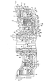
つづいて、本発明の要部となる第3のクラッチC3(第2クラッチ)及び第4のクラッチC4(第1クラッチ)について図3乃至図5に沿って説明する。
Next, the third clutch C3 (second clutch) and the fourth clutch C4 (first clutch), which are the main parts of the present invention, will be described with reference to FIGS.
本自動変速機11において、互いに隣接して配置された第3のクラッチC3及び第4のクラッチC4は、大まかに軸方向においては、変速機構31における前方部分にあって、トルクコンバータ2の後方側にあるオイルポンプ(不図示)と上記プラネタリギヤDPとの間に配置されており、径方向においては、オイルポンプのボディから延設されてケース6と一体的に形成されたボス部6aの外周側に配置されている。
In the automatic transmission 1 1, the third clutch C3 and fourth clutch C4, which are arranged adjacent to each other, in the roughly axial direction, in the front portion of the transmission mechanism 3 1, the torque converter 2 It is arranged between an oil pump (not shown) on the rear side and the planetary gear DP. In the radial direction, a boss portion 6a that extends from the body of the oil pump and is formed integrally with the case 6 is provided. It is arranged on the outer peripheral side.
なお、該ボス部6aは、詳細には、オイルポンプのボディから延設された円筒部71と、トルクコンバータ2のステータ(不図示)を支持するようにオイルポンプの内部を貫通して配置されたステータシャフト72と、が嵌合された形で一体的に形成されたものである。該ボス部6a(ステータシャフト72)の内周側には、ブッシュb1を介して入力軸7が該ボス部6aに対して回転自在に支持されており、また、上述したように該ボス部6a(ステータシャフト72)の後方側端部には、第1のサンギヤS1が固定支持されている。
More specifically, the boss portion 6a is disposed through the inside of the oil pump so as to support a cylindrical portion 71 extending from the body of the oil pump and a stator (not shown) of the torque converter 2. The stator shaft 72 and the stator shaft 72 are integrally formed. On the inner peripheral side of the boss portion 6a (stator shaft 72), the input shaft 7 is rotatably supported with respect to the boss portion 6a via a bush b1, and as described above, the boss portion 6a. The first sun gear S1 is fixedly supported at the rear side end of the (stator shaft 72).
上記第3のクラッチC3は上記第4のクラッチC4の外周側に、言い換えると、上記第4のクラッチC4は上記第3のクラッチC3の内周側に配置されている。即ち、多板式の第3のクラッチC3は、複数の外摩擦板31a及び内摩擦板31bからなる摩擦板31と、これらの摩擦板31を断接させる油圧サーボ30とを有しており、また、多板式の第4のクラッチC4は、複数の外摩擦板41a及び内摩擦板41bからなる摩擦板41と、これらの摩擦板41を断接させる油圧サーボ40とを有しており、外周側の摩擦板31が内周側の摩擦板41に一部が軸方向に対して(径方向から見て)オーバラップする形で配置されると共に、外周側の油圧サーボ30と内周側の油圧サーボ40とは略々軸方向に対してオーバラップして配置されている。
The third clutch C3 is disposed on the outer peripheral side of the fourth clutch C4, in other words, the fourth clutch C4 is disposed on the inner peripheral side of the third clutch C3. That is, the multi-plate type third clutch C3 includes a friction plate 31 including a plurality of outer friction plates 31a and inner friction plates 31b, and a hydraulic servo 30 that connects and disconnects these friction plates 31. The multi-plate fourth clutch C4 includes a friction plate 41 composed of a plurality of outer friction plates 41a and inner friction plates 41b, and a hydraulic servo 40 that connects and disconnects these friction plates 41. The friction plate 31 is disposed so as to partially overlap the inner circumferential friction plate 41 with respect to the axial direction (as viewed from the radial direction), and the outer peripheral hydraulic servo 30 and the inner peripheral hydraulic pressure are overlapped. The servo 40 is substantially overlapped with the axial direction.
ついで、第3のクラッチC3及び第4のクラッチC4の構造を詳細に説明する。上記ボス部6a上には、ベアリングb2及びスリーブ部材52を介して二重円筒状部材50が回転自在に配置されている。該二重円筒状部材50は、図3及び図5に示すように、大まかに、内周側において円筒状に形成された内側円筒部50aと、外周側において円筒状に形成された外側円筒部50cと、それら内側円筒部50a及び外側円筒部50cの前方側を連結するフランジ状部50bと、が一体的に形成されて構成されている。
Next, the structure of the third clutch C3 and the fourth clutch C4 will be described in detail. A double cylindrical member 50 is rotatably disposed on the boss portion 6a via a bearing b2 and a sleeve member 52. As shown in FIGS. 3 and 5, the double cylindrical member 50 is roughly composed of an inner cylindrical portion 50a formed in a cylindrical shape on the inner peripheral side and an outer cylindrical portion formed in a cylindrical shape on the outer peripheral side. 50c and a flange-like portion 50b that connects the front side of the inner cylindrical portion 50a and the outer cylindrical portion 50c are integrally formed.
この内側円筒部50aは、外周側に上記第4のクラッチC4の油圧サーボ40が配置される(特に後述するピストン43が摺動自在に配置される)円筒状の第1基底部を構成し、また、外側円筒部50cは、外周側に上記第3のクラッチC3の油圧サーボ30が配置される(特に後述するピストン33が摺動自在に配置される)円筒状の第2基底部を構成している。
The inner cylindrical portion 50a constitutes a cylindrical first base portion in which the hydraulic servo 40 of the fourth clutch C4 is disposed on the outer peripheral side (in particular, a piston 43 described later is slidably disposed) The outer cylindrical portion 50c constitutes a cylindrical second base portion in which the hydraulic servo 30 of the third clutch C3 is disposed on the outer peripheral side (particularly, a piston 33 described later is slidably disposed). ing.
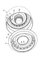
なお、詳しくは後述するように、上記外側円筒部50cの先端部50dは、図5に示すように、櫛歯状に形成されており、さらに、それら複数の先端部50dの内周側には、それぞれスナップリング溝50jが形成されている。
As will be described in detail later, the distal end portion 50d of the outer cylindrical portion 50c is formed in a comb-teeth shape as shown in FIG. 5, and further, on the inner peripheral side of the plurality of distal end portions 50d, , Each has a snap ring groove 50j.
図3に示すように、上記外側円筒部50cの外周側に配置された第3のクラッチC3の油圧サーボ30は、クラッチドラム32、ピストン33、キャンセルプレート34、リターンスプリング35を有しており、クラッチドラム32及びピストン33の間に作動油室36を構成していると共に、ピストン33及びキャンセルプレート34の間(ピストン33の作動油室36とは反対側)にキャンセル油室37を構成している。
As shown in FIG. 3, the hydraulic servo 30 of the third clutch C3 disposed on the outer peripheral side of the outer cylindrical portion 50c has a clutch drum 32, a piston 33, a cancel plate 34, and a return spring 35. A hydraulic oil chamber 36 is formed between the clutch drum 32 and the piston 33, and a cancel oil chamber 37 is formed between the piston 33 and the cancel plate 34 (on the side opposite to the hydraulic oil chamber 36 of the piston 33). Yes.
上記クラッチドラム32は、外周側のドラム部32aと前方側のフランジ状部32bとを有しており、ドラム部32aの内周側にはスプライン32sが形成されて上記外摩擦板31aがスプライン係合されていると共に、該ドラム部32aの内周側にスナップリング39が嵌合されることにより、摩擦板31の軸方向が位置決めされている。
The clutch drum 32 has an outer peripheral drum portion 32a and a front flange-shaped portion 32b. A spline 32s is formed on the inner peripheral side of the drum portion 32a, and the outer friction plate 31a is connected to the spline. In addition, the snap ring 39 is fitted to the inner peripheral side of the drum portion 32a, whereby the axial direction of the friction plate 31 is positioned.
なお、摩擦板31の内摩擦板31bは、クラッチハブ61にスプライン係合しており、該クラッチハブ61は、プラネタリギヤDPの第1のリングギヤR1に連結され(図1参照)、つまり摩擦板31の内摩擦板31bには減速回転が入力される。また、ドラム部32aの外周側には、上記第1のブレーキB1のブレーキバンドが周設されている。
The inner friction plate 31b of the friction plate 31 is spline-engaged with the clutch hub 61. The clutch hub 61 is connected to the first ring gear R1 of the planetary gear DP (see FIG. 1), that is, the friction plate 31. The reduced speed rotation is input to the inner friction plate 31b. A brake band for the first brake B1 is provided around the outer periphery of the drum portion 32a.
クラッチドラム32のフランジ状部32bの内周側は、上記二重円筒状部材50のフランジ状部50bの前方側に、例えば溶接等によって固着されており、クラッチドラム32及び二重円筒状部材50により、広義として第4のクラッチC4のクラッチドラム42を内包する第3のクラッチC3のクラッチドラムを構成している。該クラッチドラム32のフランジ状部32bの後面(図中左方側の面)は、作動油室36のシリンダ部32cとして形成されていると共に、二重円筒状部材50のフランジ状部50bとの間に隙間を存して、作動油室36用の油路c34を形成している。
The inner peripheral side of the flange-like portion 32b of the clutch drum 32 is fixed to the front side of the flange-like portion 50b of the double cylindrical member 50 by, for example, welding, and the clutch drum 32 and the double cylindrical member 50 are fixed. Thus, in a broad sense, a clutch drum of the third clutch C3 that includes the clutch drum 42 of the fourth clutch C4 is configured. The rear surface (the surface on the left side in the figure) of the flange-shaped portion 32b of the clutch drum 32 is formed as a cylinder portion 32c of the hydraulic oil chamber 36 and is connected to the flange-shaped portion 50b of the double cylindrical member 50. An oil passage c34 for the hydraulic oil chamber 36 is formed with a gap therebetween.
上記ピストン33は、その内周部が上記二重円筒状部材50の外側円筒部50cに摺動自在に支持されており、外側円筒部50cとの間がシールリングa1により、クラッチドラム32との間がシールリングa2によりシールされることで上記作動油室36を油密状に構成している。また、該ピストン33は、先端部33aにスプライン歯が形成されており、上記クラッチドラム32のスプライン32sにスプライン係合して相対回転不能に回り止めされている。
The piston 33 is slidably supported on the outer cylindrical portion 50c of the double cylindrical member 50, and the piston 33 is connected to the clutch drum 32 by a seal ring a1 between the piston 33 and the outer cylindrical portion 50c. The hydraulic oil chamber 36 is configured to be oil-tight by sealing the gap with a seal ring a2. Further, the piston 33 has spline teeth formed at the tip 33a, and is prevented from rotating relative to the spline 32s of the clutch drum 32 by spline engagement.
上記キャンセルプレート34は、その内周側が上記二重円筒状部材50の外側円筒部50cに支持されていると共に、ピストン33との間にリターンスプリング35を挟持している。また、キャンセルプレート34は、詳しくは後述する第4のクラッチC4のクラッチドラム42に当接しており、リターンスプリング35の付勢力(反力)をクラッチドラム42で受ける形となって、該キャンセルプレート34が軸方向に対して位置決め支持されている。また、該キャンセルプレート34は、外側円筒部50cとの間がシールリングa3により、ピストン33と二重円筒状部材50の外側円筒部50cとの間がシールリングa4によりシールされることで上記キャンセル油室37を油密状に構成している。
The cancel plate 34 is supported by the outer cylindrical portion 50c of the double cylindrical member 50 on the inner peripheral side, and a return spring 35 is sandwiched between the cancel plate 34 and the piston 33. The cancel plate 34 is in contact with a clutch drum 42 of a fourth clutch C4, which will be described in detail later, and receives the urging force (reaction force) of the return spring 35 by the clutch drum 42. 34 is positioned and supported with respect to the axial direction. Further, the cancel plate 34 is sealed by the seal ring a3 between the outer cylindrical portion 50c and the seal ring a4 between the piston 33 and the outer cylindrical portion 50c of the double cylindrical member 50. The oil chamber 37 is configured to be oil-tight.
一方、上記内側円筒部50aの外周側に配置された第4のクラッチC4の油圧サーボ40は、クラッチドラム42、ピストン43、キャンセルプレート44、リターンスプリング45を有しており、クラッチドラム42及びピストン43の間に作動油室46を構成していると共に、ピストン43及びキャンセルプレート44の間(ピストン43の作動油室46とは反対側)にキャンセル油室47を構成している。
On the other hand, the hydraulic servo 40 of the fourth clutch C4 disposed on the outer peripheral side of the inner cylindrical portion 50a includes a clutch drum 42, a piston 43, a cancel plate 44, and a return spring 45. The clutch drum 42 and the piston A hydraulic oil chamber 46 is formed between the piston 43 and the cancel oil chamber 47 between the piston 43 and the cancel plate 44 (on the opposite side of the piston 43 from the hydraulic oil chamber 46).
上記クラッチドラム42は、図3及び図4に示すように、外周側のドラム部42aと、径方向に略々垂直な外周円板部42bと、中間部分にて円筒状に形成された中間円筒部42dと、フランジ状に形成されたフランジ状部42eと、内周部分にて円筒状に形成された内周円筒部42fと、を一体的な一つの部材として有している。該ドラム部42aの内周側には、スプライン42sが形成されて上記外摩擦板41aがスプライン係合されていると共に、該ドラム部42aの内周側にスナップリング49が嵌合されることにより、摩擦板41の軸方向が位置決めされている。
As shown in FIGS. 3 and 4, the clutch drum 42 includes a drum portion 42a on the outer peripheral side, an outer peripheral disc portion 42b substantially perpendicular to the radial direction, and an intermediate cylinder formed in a cylindrical shape at the intermediate portion. A part 42d, a flange-like part 42e formed in a flange shape, and an inner peripheral cylindrical part 42f formed in a cylindrical shape in the inner peripheral part are provided as one integral member. A spline 42s is formed on the inner peripheral side of the drum portion 42a, and the outer friction plate 41a is engaged with the spline, and a snap ring 49 is fitted on the inner peripheral side of the drum portion 42a. The axial direction of the friction plate 41 is positioned.
なお、摩擦板41の内摩擦板41bは、クラッチハブ62にスプライン係合しており、該クラッチハブ62は、プラネタリギヤDPの第1のキャリヤCR1に連結され(図1参照)、つまり摩擦板31の内摩擦板31bには入力回転が入力される。
The inner friction plate 41b of the friction plate 41 is spline-engaged with the clutch hub 62. The clutch hub 62 is connected to the first carrier CR1 of the planetary gear DP (see FIG. 1), that is, the friction plate 31. The input rotation is input to the inner friction plate 31b.
一方、クラッチドラム42の中間円筒部42dは、二重円筒状部材50の外側円筒部50cの内周側にシールリングa6にシールされつつ嵌合しており、また、内周円筒部42fは、二重円筒状部材50の内側円筒部50aの内周側にシールリングa5にシールされつつ嵌合しており、つまりクラッチドラム42の内周側は、内側円筒部50aに支持されている。また、クラッチドラム42と二重円筒状部材50との間に上記キャンセル油室37用の油路d4を形成しており、フランジ状部42eの後面(図中左方側の面)は、作動油室46のシリンダ部42iとして形成されている。
On the other hand, the intermediate cylindrical portion 42d of the clutch drum 42 is fitted to the inner peripheral side of the outer cylindrical portion 50c of the double cylindrical member 50 while being sealed by the seal ring a6, and the inner peripheral cylindrical portion 42f is The double cylindrical member 50 is fitted to the inner peripheral side of the inner cylindrical portion 50a while being sealed by the seal ring a5. That is, the inner peripheral side of the clutch drum 42 is supported by the inner cylindrical portion 50a. An oil passage d4 for the cancel oil chamber 37 is formed between the clutch drum 42 and the double cylindrical member 50, and the rear surface (the left side surface in the figure) of the flange-shaped portion 42e is operated. The cylinder portion 42 i of the oil chamber 46 is formed.
外周円板部42bには、図4に示すように、上述した二重円筒状部材50の外側円筒部50cの櫛歯状に形成された先端部50d(図5参照)の形状に合わせた形状で貫通された複数の貫通孔42cが形成されている。そして、図3及び図4に示すように、上記二重円筒状部材50の外側円筒部50cは、先端部50dが作動油室46よりも外周部分にてクラッチドラム42の貫通孔42cを貫通して交差するように延設されており、クラッチドラム42の外周円板部42bは、二重円筒状部材50の外側円筒部50cの先端部50dにスナップリング(規制部材)51によって抜け止めする方向に規制され、つまりクラッチドラム42は、外縁付近の外周側にて二重円筒状部材50及びスナップリング51に支持されて、軸方向に対して位置決め固定されている。なお、スナップリング51は、外側円筒部50cの先端部50dの内周側から嵌合しており、外周側に嵌合するものに比して、脱落し難く構成されている。
As shown in FIG. 4, the outer peripheral disk portion 42 b has a shape that matches the shape of the tip portion 50 d (see FIG. 5) formed in the comb shape of the outer cylindrical portion 50 c of the double cylindrical member 50 described above. A plurality of through-holes 42c penetrating through are formed. As shown in FIGS. 3 and 4, the outer cylindrical portion 50 c of the double cylindrical member 50 has a distal end portion 50 d that penetrates the through hole 42 c of the clutch drum 42 at the outer peripheral portion of the hydraulic oil chamber 46. The outer peripheral disk portion 42b of the clutch drum 42 is in a direction in which it is prevented from coming off by a snap ring (regulating member) 51 at the front end portion 50d of the outer cylindrical portion 50c of the double cylindrical member 50. That is, the clutch drum 42 is supported by the double cylindrical member 50 and the snap ring 51 on the outer peripheral side in the vicinity of the outer edge, and is positioned and fixed in the axial direction. Note that the snap ring 51 is fitted from the inner peripheral side of the distal end portion 50d of the outer cylindrical portion 50c, and is configured to be less likely to drop out than that fitted to the outer peripheral side.
上記ピストン43は、図3に示すように、その内周部が上記二重円筒状部材50の内側円筒部50aに摺動自在に支持されており、内側円筒部50aとの間がシールリングa7により、クラッチドラム42との間がシールリングa8によりシールされることで上記作動油室46を油密状に構成している。また、該ピストン43は、外周側の先端部43aがスプライン状(スプライン歯)に形成されており、上記櫛歯状に形成された二重円筒状部材50の外側円筒部50cの先端部50dに係合して相対回転不能に回り止めされている。このように、該ピストン43の先端部43aを外側円筒部50cの先端部50dに係合させることで、外側円筒部50cとクラッチドラム42とを貫通して交差させる構造と共用して該ピストン43の回り止めを行うことができる。
As shown in FIG. 3, the inner periphery of the piston 43 is slidably supported by the inner cylindrical portion 50a of the double cylindrical member 50, and a seal ring a7 is provided between the piston 43 and the inner cylindrical portion 50a. Thus, the hydraulic oil chamber 46 is configured to be oil-tight by sealing the space between the clutch drum 42 by the seal ring a8. The piston 43 has a distal end portion 43a on the outer peripheral side formed in a spline shape (spline teeth), and is formed on the distal end portion 50d of the outer cylindrical portion 50c of the double cylindrical member 50 formed in the comb tooth shape. Engagement prevents rotation against relative rotation. Thus, the piston 43 is used in common with the structure in which the outer cylindrical portion 50c and the clutch drum 42 are crossed by engaging the tip portion 43a of the piston 43 with the tip portion 50d of the outer cylindrical portion 50c. Can be prevented.
なお、このピストン43の先端部43aの厚みは、第4のクラッチC4の係脱に際して移動するピストンストロークよりも厚く形成されており、第4のクラッチC4を係合した際にも、二重円筒状部材50の外側円筒部50cの先端部50dから脱落することはない。また、該ピストン43には、クラッチドラム42側の面に突起部43bが形成されており、該ピストン43が該クラッチドラム42に隙間なく貼り付くことを防止している。
The tip 43a of the piston 43 is formed thicker than the piston stroke that moves when the fourth clutch C4 is engaged and disengaged, and even when the fourth clutch C4 is engaged, the double cylinder The tip 50d of the outer cylindrical portion 50c of the shaped member 50 does not fall off. Further, the piston 43 is formed with a projection 43b on the surface on the clutch drum 42 side to prevent the piston 43 from sticking to the clutch drum 42 without a gap.
上記キャンセルプレート44は、その内周部が上記二重円筒状部材50の内側円筒部50aに支持されていると共に、ピストン43との間にリターンスプリング45を挟持しており、かつスナップリング48によりリターンスプリング45の付勢力(反力)を受ける形で、つまりキャンセルプレート44はスナップリング48により軸方向に位置決め固定されている。また、キャンセルプレート44は、ピストン43との間がシールリングa9によりシールされることで上記キャンセル油室47を油密状に構成している。
The cancel plate 44 has an inner peripheral portion supported by the inner cylindrical portion 50 a of the double cylindrical member 50, a return spring 45 sandwiched between the piston 43, and a snap ring 48. The cancel plate 44 is positioned and fixed in the axial direction by a snap ring 48 so as to receive an urging force (reaction force) of the return spring 45. The cancel plate 44 is sealed with the piston 43 by a seal ring a9, so that the cancel oil chamber 47 is configured in an oil-tight manner.
ついで、第3のクラッチC3及び第4のクラッチC4に関する油路構造について図3に沿って説明する。第3のクラッチC3の油圧サーボ30の作動油室36に供給される油、即ち第3のクラッチC3の作動油圧は、図示を省略した油圧制御装置(バルブボディ)からオイルポンプボディ等に形成された油路を介して、上記ボス部6a内に形成された油路c31に導かれている。
Next, the oil passage structure relating to the third clutch C3 and the fourth clutch C4 will be described with reference to FIG. The oil supplied to the hydraulic oil chamber 36 of the hydraulic servo 30 of the third clutch C3, that is, the hydraulic pressure of the third clutch C3 is formed in an oil pump body or the like from a hydraulic control device (valve body) (not shown). The oil passage c31 formed in the boss portion 6a is guided through the oil passage.
該油路c31は、外周側に向けて穿設された油路c32に連通しており、シールリングa11,a12にシールされて、スリーブ部材52の貫通孔52aに連通される。該貫通孔52aは、スリーブ部材52と二重円筒状部材50との間に形成された油路c33に連通され、さらに、二重円筒状部材50の内側円筒部50aの内周面からフランジ状部50bの前面(図中右方側の面)まで貫通形成された貫通孔50eに連通される。そして、該貫通孔50eは、上述したように二重円筒状部材50とクラッチドラム32との間に形成された油路c34に連通されており、該油路c34は作動油室36に連通されている。
The oil passage c31 communicates with an oil passage c32 that is drilled toward the outer peripheral side, is sealed by seal rings a11 and a12, and communicates with the through hole 52a of the sleeve member 52. The through-hole 52a is communicated with an oil passage c33 formed between the sleeve member 52 and the double cylindrical member 50, and is further flanged from the inner peripheral surface of the inner cylindrical portion 50a of the double cylindrical member 50. The portion 50b communicates with a through hole 50e formed to penetrate to the front surface (the surface on the right side in the drawing). The through hole 50e communicates with the oil passage c34 formed between the double cylindrical member 50 and the clutch drum 32 as described above, and the oil passage c34 communicates with the hydraulic oil chamber 36. ing.
なお、本実施の形態において、「第3のクラッチC3の作動油圧の供給油路」とは、油路c31、油路c32、スリーブ部材52の貫通孔52a、油路c33、貫通孔50e、油路c34を指し、「作動油室36」とは、二重円筒状部材50の外側円筒部50cの外周面よりも外周側であって、ピストン33を押圧するチャンバ面積に対応した部分を指す。
In the present embodiment, “the hydraulic oil supply oil passage of the third clutch C3” means the oil passage c31, the oil passage c32, the through hole 52a of the sleeve member 52, the oil passage c33, the through hole 50e, the oil The hydraulic fluid chamber 36 refers to a portion that is on the outer peripheral side of the outer peripheral surface of the outer cylindrical portion 50 c of the double cylindrical member 50 and that corresponds to the chamber area that presses the piston 33.
一方、第4のクラッチC4の油圧サーボ40の作動油室46に供給される油、即ち第4のクラッチC4の作動油圧は、図示を省略した油圧制御装置(バルブボディ)からオイルポンプボディ等に形成された油路を介して、上記ボス部6a内に形成された油路c41に導かれている。
On the other hand, the oil supplied to the hydraulic oil chamber 46 of the hydraulic servo 40 of the fourth clutch C4, that is, the hydraulic pressure of the fourth clutch C4 is transferred from a hydraulic control device (valve body) (not shown) to the oil pump body and the like. It is led to the oil passage c41 formed in the boss portion 6a through the formed oil passage.
該油路c41は、外周側に向けて穿設された油路c42に連通しており、シールリングa13,a14にシールされて、スリーブ部材52の貫通孔52cに連通される。該貫通孔52cは、スリーブ部材52と二重円筒状部材50との間に形成された油路c43に連通され、さらに、二重円筒状部材50の内側円筒部50aの内周面から外周面まで貫通形成された貫通孔50gに連通される。そして、該貫通孔50gの外周側出口は作動油室46に連通されている。
The oil passage c41 communicates with an oil passage c42 drilled toward the outer peripheral side, is sealed by seal rings a13 and a14, and communicates with the through hole 52c of the sleeve member 52. The through hole 52 c communicates with an oil passage c 43 formed between the sleeve member 52 and the double cylindrical member 50, and further, from the inner peripheral surface to the outer peripheral surface of the inner cylindrical portion 50 a of the double cylindrical member 50. It communicates with the through-hole 50g formed through. The outer peripheral side outlet of the through hole 50g communicates with the hydraulic oil chamber 46.
なお、本実施の形態において、「第4のクラッチC4の作動油圧の供給油路」とは、油路c41、油路c42、スリーブ部材52の貫通孔52c、油路c43、貫通孔50gを指し、「作動油室46」とは、二重円筒状部材50の内側円筒部50aの外周面よりも外周側であって、ピストン43を押圧するチャンバ面積に対応した部分を指す。
In the present embodiment, the “hydraulic oil supply passage for the fourth clutch C4” refers to the oil passage c41, the oil passage c42, the through hole 52c of the sleeve member 52, the oil passage c43, and the through hole 50g. The “hydraulic oil chamber 46” refers to a portion corresponding to a chamber area that presses the piston 43 on the outer peripheral side of the inner cylindrical portion 50 a of the double cylindrical member 50.
また、第3のクラッチC3及び第4のクラッチC4のキャンセル油室37,47に供給される油は、例えば潤滑油として供給される油が用いられており、図示を省略した油圧制御装置(バルブボディ)からオイルポンプボディ等に形成された油路を介して、上記ボス部6a内に形成された油路d1に導かれている。
The oil supplied to the cancel oil chambers 37 and 47 of the third clutch C3 and the fourth clutch C4 is, for example, oil supplied as lubricating oil, and a hydraulic control device (valve not shown) is used. The body) is led to an oil passage d1 formed in the boss portion 6a through an oil passage formed in the oil pump body or the like.
該油路d1は、外周側に向けて穿設された油路d2に連通しており、シールリングa12,a13にシールされて、スリーブ部材52の貫通孔52bに連通され、さらに該貫通孔52bは、スリーブ部材52と二重円筒状部材50との間に形成された油路d3に連通される。該油路d3は、二重円筒状部材50の内側円筒部50aの内周面から外周面まで貫通形成された貫通孔50hに連通されており、該貫通孔50hの外周側出口が第4のクラッチC4のキャンセル油室47に連通されている。さらに、上記クラッチC4のピストン43が駆動されてキャンセル油室47が狭まった際には、キャンセルプレート44の内周側に形成された切り欠き44aから、前記キャンセル油室47内の油が遠心力により外周側に向けて飛散される。
The oil passage d1 communicates with an oil passage d2 drilled toward the outer peripheral side, is sealed by seal rings a12 and a13, communicates with the through hole 52b of the sleeve member 52, and further includes the through hole 52b. Is communicated with an oil passage d3 formed between the sleeve member 52 and the double cylindrical member 50. The oil passage d3 communicates with a through hole 50h formed through the inner cylindrical surface 50a of the double cylindrical member 50 from the inner peripheral surface to the outer peripheral surface, and the outer peripheral outlet of the through hole 50h is the fourth outlet. The clutch C4 communicates with a cancel oil chamber 47. Furthermore, when the piston 43 of the clutch C4 is driven and the cancel oil chamber 47 is narrowed, the oil in the cancel oil chamber 47 is centrifugally forced from the notches 44a formed on the inner peripheral side of the cancel plate 44. Is scattered toward the outer peripheral side.
一方、上記油路d3は、二重円筒状部材50の内側円筒部50aに貫通形成された貫通孔50fにも連通されており、該貫通孔50fは、上述したように二重円筒状部材50とクラッチドラム42との間に形成された油路d4に連通されている。さらに、該油路d4は、二重円筒状部材50の外側円筒部50cに貫通形成された貫通孔50iに連通されており、該貫通孔50iの外周側出口が第3のクラッチC3のキャンセル油室37に連通されている。また、上記クラッチC3のピストン33が駆動されてキャンセル油室37が狭まった際には、貫通孔50i、油路d4、貫通孔50f、油路d3、貫通孔50h、第4のクラッチC4のキャンセル油室47を介して切り欠き44aから、前記キャンセル油室37内の油が遠心力により外周側に向けて飛散される。これにより、該キャンセル油室37内の油は一旦クラッチC4のキャンセル油室47に供給され、該キャンセル油室47の油と一緒に切り欠き44aから排出される。よってクラッチC3とクラッチC4のキャンセル油室の油の排出経路を共通化できるため、それぞれ別の排出経路を設置する場合に比べ、油路の加工工数を低減できる。
On the other hand, the oil passage d3 is also communicated with a through hole 50f formed through the inner cylindrical portion 50a of the double cylindrical member 50. The through hole 50f is connected to the double cylindrical member 50 as described above. And an oil passage d4 formed between the clutch drum 42 and the clutch drum 42. Further, the oil passage d4 is communicated with a through hole 50i formed through the outer cylindrical portion 50c of the double cylindrical member 50, and an outer peripheral side outlet of the through hole 50i is a cancel oil of the third clutch C3. It communicates with the chamber 37. When the piston 33 of the clutch C3 is driven and the cancel oil chamber 37 is narrowed, the through hole 50i, the oil passage d4, the through hole 50f, the oil passage d3, the through hole 50h, and the fourth clutch C4 are canceled. Through the oil chamber 47, the oil in the cancel oil chamber 37 is scattered from the notch 44a toward the outer peripheral side by centrifugal force. As a result, the oil in the cancel oil chamber 37 is once supplied to the cancel oil chamber 47 of the clutch C4 and discharged together with the oil in the cancel oil chamber 47 from the notch 44a. Therefore, since the oil discharge path of the cancellation oil chambers of the clutch C3 and the clutch C4 can be made common, it is possible to reduce the number of processing steps of the oil path as compared with the case where separate discharge paths are provided.
なお、本実施の形態において、「第4のクラッチC4のキャンセル油室47の油路」とは、油路d1、油路d2、スリーブ部材52の貫通孔52b、油路d3、貫通孔50hを指し、「キャンセル油室47」とは、二重円筒状部材50の内側円筒部50aの外周面よりも外周側であって、ピストン43に遠心油圧を作用させる有効面積に対応した部分を指す。また、「第3のクラッチC3のキャンセル油室37の油路」とは、油路d1、油路d2、スリーブ部材52の貫通孔52b、油路d3、貫通孔50f、油路d4、貫通孔50iを指し、「キャンセル油室37」とは、二重円筒状部材50の外側円筒部50cの外周面よりも外周側であって、ピストン33に遠心油圧を作用させる有効面積に対応した部分を指す。
In the present embodiment, “the oil passage of the cancel oil chamber 47 of the fourth clutch C4” means the oil passage d1, the oil passage d2, the through hole 52b of the sleeve member 52, the oil passage d3, and the through hole 50h. The “cancellation oil chamber 47” refers to a portion corresponding to an effective area on the outer peripheral surface of the inner cylindrical portion 50 a of the double cylindrical member 50 and corresponding to the centrifugal oil pressure acting on the piston 43. The “oil path of the cancel oil chamber 37 of the third clutch C3” means the oil path d1, the oil path d2, the through hole 52b of the sleeve member 52, the oil path d3, the through hole 50f, the oil path d4, the through hole. 50i indicates that the “cancellation oil chamber 37” is a portion on the outer peripheral side of the outer cylindrical surface 50c of the double cylindrical member 50 and corresponding to an effective area for applying centrifugal hydraulic pressure to the piston 33. Point to.
また、上記油路d1には、後方側からベアリングb2に向けて油路d5が穿設されている。これにより、ベアリングやプラネタリギヤDP(図1参照)に潤滑油を供給できる。
Further, an oil passage d5 is formed in the oil passage d1 from the rear side toward the bearing b2. Thereby, lubricating oil can be supplied to a bearing or planetary gear DP (refer FIG. 1).
ついで、第3のクラッチC3及び第4のクラッチC4における作用を説明する。第4のクラッチC4の解放状態から係合が判断されると、不図示の油圧制御装置から第4のクラッチC4の作動油室46に係合圧が供給され、ピストン43がリターンスプリング45の付勢力に抗して二重円筒状部材50の内側円筒部50a上を摺動し、後方側に駆動されて摩擦板41を押圧し、該摩擦板41を係合させる。
Next, the operation of the third clutch C3 and the fourth clutch C4 will be described. When engagement is determined from the disengaged state of the fourth clutch C4, an engagement pressure is supplied from a hydraulic control device (not shown) to the hydraulic oil chamber 46 of the fourth clutch C4, and the piston 43 is attached to the return spring 45. It slides on the inner cylindrical portion 50a of the double cylindrical member 50 against the force and is driven rearward to press the friction plate 41 to engage the friction plate 41.
この際、ピストン43が作動油室46の係合圧によって後方側(図中左方側)に押圧する力は、摩擦板41及びスナップリング49を介してクラッチドラム42のドラム部42aに伝達され、クラッチドラム42において作動油室46の係合圧によって前方側(図中右方側)に押圧する力と釣り合い、つまり力学的な閉ループ系が成立する。
At this time, the force that the piston 43 presses to the rear side (left side in the figure) by the engagement pressure of the hydraulic oil chamber 46 is transmitted to the drum portion 42 a of the clutch drum 42 via the friction plate 41 and the snap ring 49. The clutch drum 42 balances with the force pressed forward (right side in the figure) by the engagement pressure of the hydraulic oil chamber 46, that is, a dynamic closed loop system is established.
また、第4のクラッチC4が解放された際は、リターンスプリング45によりピストン43が前方側に押戻される。このリターンスプリング45の付勢力についても、ピストン43がクラッチドラム42に当接するため、二重円筒状部材50を介して同様に閉ループ系が成立する。この際、第4のクラッチC4の油圧サーボ40が回転中であっても、作動油室46にある油とキャンセル油室47にある油とに生じる遠心力に基づく遠心油圧は、ピストン43に対して互いに打ち消す方向に作用し、また、クラッチドラム42を前方側に押圧する遠心油圧は油路d4に生じる遠心油圧と釣り合い、さらに、キャンセルプレート44を後方側に押圧する遠心油圧は、スナップリング48を介して二重円筒状部材50の内側円筒部50aに作用し、油路d4に生じる遠心油圧により二重円筒状部材50のフランジ状部50bを前方側(図中右方側)に押圧する力と閉ループ系となって互いに打ち消され、つまり油圧サーボ40に生じる遠心油圧は完全にキャンセルされる。
When the fourth clutch C4 is released, the piston 43 is pushed back by the return spring 45. With respect to the urging force of the return spring 45 as well, since the piston 43 abuts on the clutch drum 42, a closed loop system is similarly established via the double cylindrical member 50. At this time, even if the hydraulic servo 40 of the fourth clutch C4 is rotating, the centrifugal hydraulic pressure based on the centrifugal force generated in the oil in the hydraulic oil chamber 46 and the oil in the cancel oil chamber 47 is applied to the piston 43. The centrifugal hydraulic pressure acting on the clutch drum 42 forward is balanced with the centrifugal hydraulic pressure generated in the oil passage d4, and the centrifugal hydraulic pressure pushing the cancel plate 44 rearward is the snap ring 48. Acting on the inner cylindrical portion 50a of the double cylindrical member 50 and pressing the flange-like portion 50b of the double cylindrical member 50 forward (to the right in the figure) by the centrifugal hydraulic pressure generated in the oil passage d4. The force and the closed loop system cancel each other, that is, the centrifugal hydraulic pressure generated in the hydraulic servo 40 is completely canceled.
一方、第3のクラッチC3の解放状態から係合が判断されると、不図示の油圧制御装置から第3のクラッチC3の作動油室36に係合圧が供給され、ピストン33がリターンスプリング35の付勢力に抗して二重円筒状部材50の外側円筒部50c上を摺動し、後方側に駆動されて摩擦板31を押圧し、該摩擦板31を係合させる。
On the other hand, when engagement is determined from the released state of the third clutch C3, engagement pressure is supplied from a hydraulic control device (not shown) to the hydraulic oil chamber 36 of the third clutch C3, and the piston 33 is returned to the return spring 35. It slides on the outer cylindrical portion 50c of the double cylindrical member 50 against the urging force, and is driven rearward to press the friction plate 31 to engage the friction plate 31.
この際、ピストン33が作動油室36の係合圧によって後方側(図中左方側)に押圧する力は、摩擦板31及びスナップリング39を介してクラッチドラム32のドラム部32aに伝達され、クラッチドラム32において作動油室36の係合圧によって前方側(図中右方側)に押圧する力と釣り合い、つまり力学的な閉ループ系が成立する。
At this time, the force that the piston 33 presses to the rear side (left side in the figure) by the engagement pressure of the hydraulic oil chamber 36 is transmitted to the drum portion 32 a of the clutch drum 32 via the friction plate 31 and the snap ring 39. The clutch drum 32 balances with the force pressed forward (rightward in the figure) by the engagement pressure of the hydraulic oil chamber 36, that is, a dynamic closed loop system is established.
また、第3のクラッチC3が解放された際は、リターンスプリング35によりピストン33が前方側に押戻される。このリターンスプリング35の付勢力は、ピストン33がクラッチドラム32に当接するため、リターンスプリング35、キャンセルプレート34、クラッチドラム42、スナップリング51を介して二重円筒状部材50の外側円筒部50cに伝達される。これらの力は、特にスナップリング51から受けた力が、一体的に構成された二重円筒状部材50からクラッチドラム32に伝達されることと相俟って、作動油室36の係合圧によりクラッチドラム32のシリンダ部32cに生じる前方側(図中右方側)への押圧力と打ち消され、つまり二重円筒状部材50を介して同様に閉ループ系が成立する。この際、第3のクラッチC3の油圧サーボ30が回転中であっても、作動油室36にある油とキャンセル油室37にある油とに生じる遠心力に基づく遠心油圧は、ピストン33に対して互いに打ち消す方向に作用し、また、クラッチドラム32を前方側に押圧する遠心油圧やキャンセルプレート34を後方側に押圧する遠心油圧は、上述と同様に閉ループ系にあって互いに打ち消され、つまり油圧サーボ30に生じる遠心油圧は完全にキャンセルされる。
When the third clutch C3 is released, the piston 33 is pushed back by the return spring 35. The biasing force of the return spring 35 is applied to the outer cylindrical portion 50 c of the double cylindrical member 50 via the return spring 35, the cancel plate 34, the clutch drum 42, and the snap ring 51 because the piston 33 abuts on the clutch drum 32. Communicated. In particular, the force received from the snap ring 51 is transmitted to the clutch drum 32 from the integrally formed double cylindrical member 50, and the engagement pressure of the hydraulic oil chamber 36 is combined. Accordingly, the forward pressing force (right side in the figure) generated in the cylinder portion 32c of the clutch drum 32 is canceled, that is, a closed loop system is similarly established via the double cylindrical member 50. At this time, even if the hydraulic servo 30 of the third clutch C3 is rotating, the centrifugal hydraulic pressure based on the centrifugal force generated in the oil in the hydraulic oil chamber 36 and the oil in the cancel oil chamber 37 is applied to the piston 33. The centrifugal hydraulic pressure that presses the clutch drum 32 forward and the centrifugal hydraulic pressure that presses the cancel plate 34 rearward are canceled in the closed loop system in the same manner as described above. The centrifugal hydraulic pressure generated in the servo 30 is completely canceled.
ところで、上述のように第3のクラッチC3の油圧サーボ30では、一応の力学的な閉ループが成立しているものの、キャンセルプレート34に生じる後方側(図中左方側)への押圧力、特にキャンセル油室37の遠心油圧により生じる力は、第4のクラッチC4のクラッチドラム42を押圧してしまう。また、キャンセル油室37に連通する油路d4における油にも遠心油圧が生じるため、該油路d4の遠心油圧によっても、クラッチドラム42が後方側に押し圧されてしまう。
By the way, in the hydraulic servo 30 of the third clutch C3 as described above, although a temporarily closed dynamic loop is established, the pressing force to the rear side (left side in the figure) generated in the cancel plate 34, particularly The force generated by the centrifugal oil pressure in the cancel oil chamber 37 presses the clutch drum 42 of the fourth clutch C4. Further, since the centrifugal oil pressure is also generated in the oil in the oil passage d4 communicating with the cancel oil chamber 37, the clutch drum 42 is pressed backward by the centrifugal oil pressure in the oil passage d4.
しかしながら、本自動変速機11によれば、二重円筒状部材50の外側円筒部50cを、その先端部50dが第4のクラッチC4のクラッチドラム42を作動油室46よりも外周部分にて貫通して交差するように延設し、該クラッチドラム42を、スナップリング51によって貫通された外側円筒部50cの先端部50dに対して抜止めする方向に規制して、特に肉厚が厚く形成されて強固に形成された二重円筒状部材50の外側円筒部50cに支持させたので、スナップリング51及び外側円筒部50cによってクラッチドラム42をより外周側にて支持することができる。
However, according to the automatic transmission 11 , the outer cylindrical portion 50 c of the double cylindrical member 50, and the distal end portion 50 d of the clutch drum 42 of the fourth clutch C 4 at the outer peripheral portion than the hydraulic oil chamber 46. It extends so as to penetrate and intersect, and the clutch drum 42 is restricted in a direction in which the clutch drum 42 is prevented from being pulled out with respect to the front end portion 50d of the outer cylindrical portion 50c penetrated by the snap ring 51, so that the wall thickness is particularly thick. Since the outer cylindrical portion 50c of the double-cylindrical member 50 formed firmly is supported by the snap ring 51 and the outer cylindrical portion 50c, the clutch drum 42 can be supported on the outer peripheral side.
即ち、例えばクラッチドラム42を内側円筒部50aにスナップリング等によって位置決め固定した場合に比して、外側円筒部50cによって該クラッチドラム42を外周側にて支持することができたので、該クラッチドラム42に生じるモーメントの支点が外周側となり、内周側を支点とした大きな捩れモーメントが生じることを防止することができて、該クラッチドラム42の変形の防止を図ることができる。
That is, for example, compared to the case where the clutch drum 42 is positioned and fixed to the inner cylindrical portion 50a by a snap ring or the like, the outer cylindrical portion 50c can support the clutch drum 42 on the outer peripheral side. Since the fulcrum of the moment generated in 42 is on the outer peripheral side, it is possible to prevent a large torsional moment from occurring on the inner peripheral side and to prevent deformation of the clutch drum 42.
従って、例えばコンパクト性を維持するために第4のクラッチC4と第3のクラッチC3とを隣接配置し、第3のクラッチC3のキャンセル油室37の遠心油圧により該第4のクラッチC4のクラッチドラム42を背面側から押圧したとしても、該第4のクラッチC4のクラッチドラム42の肉厚を厚くすることなく、該クラッチドラム42の変形を防止することができ、つまりコンパクト性を維持しながら、耐久性の向上を図ることができ、また、摩擦板41の姿勢に悪影響を与えることがなくて、クラッチ制御性の向上も図ることができる。
Therefore, for example, in order to maintain compactness, the fourth clutch C4 and the third clutch C3 are disposed adjacent to each other, and the clutch drum of the fourth clutch C4 is provided by the centrifugal hydraulic pressure of the cancel oil chamber 37 of the third clutch C3. Even if 42 is pressed from the back side, it is possible to prevent deformation of the clutch drum 42 without increasing the thickness of the clutch drum 42 of the fourth clutch C4, that is, while maintaining compactness, The durability can be improved, and the clutch controllability can be improved without adversely affecting the posture of the friction plate 41.
また、本自動変速機11にあっては、第3のクラッチC3のキャンセルプレート34を、外側円筒部50c上に配置すると共に、第4のクラッチC4のクラッチドラム42に直接当接支持させたので、例えば第3のクラッチC3のキャンセルプレート34を外側円筒部50cに対してスナップリング等により位置決め支持させる場合に比して、スナップリングを1個減らせる分、軸方向に対するコンパクト化を図ることを可能としている。このように、キャンセルプレート34をクラッチドラム42に直接支持させてしまうと、キャンセルプレート34を介してキャンセル油室37の遠心油圧がクラッチドラム42に作用してしまうが、本自動変速機11にあっては、上述のようにクラッチドラム42をより外周側にて支持することができるので、該クラッチドラム42の変形を防止しつつ、スナップリングの減少も可能にしている。
Further, in this automatic transmission 1 1, the cancel plate 34 of the third clutch C3, as well as disposed on the outer cylindrical portion 50c, was directly in contact supported on the clutch drum 42 of the fourth clutch C4 Therefore, for example, compared with the case where the cancel plate 34 of the third clutch C3 is positioned and supported by the snap ring or the like with respect to the outer cylindrical portion 50c, the snap ring can be reduced by one, so that the axial direction can be made compact. Is possible. Thus, the cancel plate 34 when thus is supported directly on the clutch drum 42, although centrifugal hydraulic pressure of the cancel oil chamber 37 through the cancel plate 34 will act on the clutch drum 42, to the automatic transmission 1 1 In this case, the clutch drum 42 can be supported on the outer peripheral side as described above, so that the snap ring can be reduced while preventing the clutch drum 42 from being deformed.
また特に、内側円筒部50aと外側円筒部50cとはフランジ状部50bを介して一体的に形成されており、つまり二重円筒状部材50は、元々、油圧サーボ30と油圧サーボ40との2つの油圧サーボを支持するため、肉厚が厚く、内側円筒部50aと外側円筒部50cとが一体的に形成された、非常に強固な部材として形成されているので、クラッチドラム42を支持(補強)する部材として充分な強度を備えており、それによって、クラッチドラム42の変形を防止することを可能としている。
In particular, the inner cylindrical portion 50a and the outer cylindrical portion 50c are integrally formed via the flange-shaped portion 50b. That is, the double cylindrical member 50 is originally composed of the hydraulic servo 30 and the hydraulic servo 40. In order to support the two hydraulic servos, the clutch drum 42 is supported (reinforced) because it is formed as a very strong member having a large thickness and the inner cylindrical portion 50a and the outer cylindrical portion 50c integrally formed. ) Has a sufficient strength as a member to prevent the clutch drum 42 from being deformed.
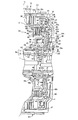
次に、上述した自動変速機11を一部変更した別の実施の形態として、自動変速機12を図6に沿って説明する。なお、本自動変速機12の説明においては、主に、上記自動変速機11に対する変更部分だけを説明し、同一部分には同符号を付して、その説明を省略する。
Next, as another embodiment in which the above-described automatic transmission 11 is partially changed, the automatic transmission 12 will be described with reference to FIG. In the description of the automatic transmission 1 2, mainly describes only changed portions with respect to the automatic transmission 1 1, the same portions are denoted by the same reference numerals, and description thereof is omitted.
本自動変速機12は、図6に示すように、上記自動変速機11に比して(図3参照)、クラッチドラム42を、摩擦板41がスプライン係合するドラム部材42Aと、作動油室46を構成するシリンダ部材42Bとに分割して形成したものである。
The automatic transmission 1 2, as shown in FIG. 6, as compared to the automatic transmission 1 1 (see FIG. 3), the drum member 42A of the clutch drum 42, the friction plate 41 spline-engaged, operation The oil chamber 46 is divided and formed into a cylinder member 42B.
詳細には、本自動変速機12の自動変速機構32において、クラッチドラム42のドラム部材42Aは、スプライン42sが形成されたドラム部42aと、上述の貫通孔42cが形成された外周円板部42bとの部分だけで構成されており、一方のシリンダ部材42Bは、円筒状に形成された中間円筒部42dと、フランジ状に形成されたフランジ状部42eと、内周部分にて円筒状に形成された内周円筒部42fとの部分だけで構成されている。また、シリンダ部材42Bは、中間円筒部42dの先端部分が、ドラム部材42Aの外周円板部42bの内周部分に当接支持されて、二重円筒状部材50に対して位置決め支持されている。
Specifically, in the automatic speed change mechanism 3 2 of the automatic transmission 1 2, the drum member 42A of the clutch drum 42 includes a drum portion 42a spline 42s is formed, the outer periphery disc through-hole 42c described above is formed The cylinder member 42B is composed of an intermediate cylindrical portion 42d formed in a cylindrical shape, a flange-shaped portion 42e formed in a flange shape, and a cylindrical shape in an inner peripheral portion. It is comprised only by the part with the inner peripheral cylindrical part 42f formed. Further, the cylinder member 42B is positioned and supported with respect to the double cylindrical member 50 with the tip end portion of the intermediate cylindrical portion 42d being in contact with and supported by the inner peripheral portion of the outer peripheral disc portion 42b of the drum member 42A. .
なお、本実施の形態においても、ドラム部材42Aに貫通孔42cを形成することで、二重円筒状部材50の外側円筒部50cの先端部50dを貫通して交差させているが、ドラム部材42Aとシリンダ部材42Bとが分割されているため、ドラム部材42Aの外周円板部42bの内周側を櫛歯状に形成しても構わない。
Also in the present embodiment, the through hole 42c is formed in the drum member 42A so as to penetrate and intersect the distal end portion 50d of the outer cylindrical portion 50c of the double cylindrical member 50, but the drum member 42A. Since the cylinder member 42B and the cylinder member 42B are divided, the inner peripheral side of the outer peripheral disc portion 42b of the drum member 42A may be formed in a comb shape.
このように自動変速機12においては、シリンダ部材42Bを、スプライン42sを有するドラム部材42Aと分割することで、該シリンダ部材42Bをプレス加工により形成することを可能とし、コストダウンを図ることを可能としている。
In this way, the automatic transmission 1 2, the cylinder member 42B, by dividing the drum member 42A having the spline 42s, the cylinder member 42B make it possible to form by pressing, that reduce the cost It is possible.
また、シリンダ部材42Bのフランジ状部42eは、ピストン43側に突出する第1突起部42gと、二重円筒状部材50のフランジ状部50b側に突出する第2突起部42hとを有しており、これら第1及び第2突起部42g,42hは、同径上の異なる位置に位相をずらして配置されている。このように構成することで、簡単なプレス加工だけでシリンダ部材42Bを形成することを可能とし、かつシリンダ部材42Bとピストン43との貼り付き防止や、シリンダ部材42Bとフランジ状部50bとの間に形成された油路d4のクリアランス確保を図ることを可能としている。
Further, the flange-like portion 42e of the cylinder member 42B has a first protrusion 42g that protrudes toward the piston 43 and a second protrusion 42h that protrudes toward the flange-like portion 50b of the double cylindrical member 50. The first and second protrusions 42g and 42h are arranged with different phases at different positions on the same diameter. With this configuration, it is possible to form the cylinder member 42B only by a simple press work, prevent sticking between the cylinder member 42B and the piston 43, and between the cylinder member 42B and the flange-shaped portion 50b. It is possible to ensure the clearance of the oil passage d4 formed in the above.
さらに、本自動変速機12のクラッチドラム42においては、キャンセルプレート34から受ける力、油路d4の遠心油圧により受ける力が、後方側に向けて生じても、クラッチドラム42全体が内周部分を支点として捩れるように変形することがなく、特にドラム部材42Aは、全体的に後方側に僅かに移動することがあっても、摩擦板41の姿勢が傾くことはなく、クラッチ制御性の向上を図ることができる。
Further, in the clutch drum 42 of the automatic transmission 1 2, the force received from the cancel plate 34, the force experienced by centrifugal hydraulic pressure in the oil passage d4, even if toward the rear side, the inner peripheral portion across the clutch drum 42 is The drum member 42A is not deformed so as to be twisted with the fulcrum as a fulcrum, and even if the drum member 42A moves slightly rearward as a whole, the posture of the friction plate 41 is not inclined, and the clutch controllability is improved. Improvements can be made.
なお、上述した部分以外の作用効果は、上記自動変速機11と同様であるので、その説明を省略する。
Incidentally, operation and effect other than the portion mentioned above are the same as the automatic transmission 1 1, the description thereof is omitted.
なお、以上説明した本実施の形態においては、多段式自動変速機として前進8速段及び後進2速段を達成するものにあって、第3のクラッチC3及び第4のクラッチC4に本発明を適用したものを一例に説明したが、これに限らず、2つのクラッチが隣接配置される自動変速機であれば、どのような自動変速機にあっても本発明を適用し得る。
In the embodiment described above, the multi-stage automatic transmission achieves the eighth forward speed and the second reverse speed, and the present invention is applied to the third clutch C3 and the fourth clutch C4. Although the application is described as an example, the present invention is not limited to this, and the present invention can be applied to any automatic transmission as long as the two clutches are adjacently arranged.
また、以上説明した本実施の形態においては、第3のクラッチC3の油圧サーボ30及び第4のクラッチC4の油圧サーボ40が内外周側に二階建てのように配置されたものを一例に説明したが、これに限らず、一方のクラッチのクラッチドラムに他方のクラッチの油圧サーボに発生する力が伝達されるものであれば、どのようなものであっても本発明を適用し得る。油圧サーボに発生する力とは、油圧サーボの内部で生じる力だけに限らず、本実施の形態のように、油圧サーボまでの油路(例えば油路d4等)に生じる力も含めたものである。
Further, in the present embodiment described above, the hydraulic servo 30 of the third clutch C3 and the hydraulic servo 40 of the fourth clutch C4 are described as an example on the inner and outer peripheral sides in a two-story manner. However, the present invention is not limited to this, and the present invention can be applied to any type as long as the force generated in the hydraulic servo of the other clutch is transmitted to the clutch drum of the one clutch. The force generated in the hydraulic servo is not limited to the force generated in the hydraulic servo, but also includes the force generated in the oil passage (for example, the oil passage d4) up to the hydraulic servo as in the present embodiment. .