JP2018013169A - Power transmission device - Google Patents
Power transmission device Download PDFInfo
- Publication number
- JP2018013169A JP2018013169A JP2016142688A JP2016142688A JP2018013169A JP 2018013169 A JP2018013169 A JP 2018013169A JP 2016142688 A JP2016142688 A JP 2016142688A JP 2016142688 A JP2016142688 A JP 2016142688A JP 2018013169 A JP2018013169 A JP 2018013169A
- Authority
- JP
- Japan
- Prior art keywords
- spline
- power transmission
- urging
- transmission device
- fixing
- Prior art date
- Legal status (The legal status is an assumption and is not a legal conclusion. Google has not performed a legal analysis and makes no representation as to the accuracy of the status listed.)
- Pending
Links
- 230000005540 biological transmission Effects 0.000 title claims abstract description 85
- 230000002093 peripheral effect Effects 0.000 claims description 23
- 238000003825 pressing Methods 0.000 description 7
- 238000002485 combustion reaction Methods 0.000 description 6
- 229910000831 Steel Inorganic materials 0.000 description 4
- 230000006835 compression Effects 0.000 description 4
- 238000007906 compression Methods 0.000 description 4
- 239000010959 steel Substances 0.000 description 4
- 230000002542 deteriorative effect Effects 0.000 description 3
- XEEYBQQBJWHFJM-UHFFFAOYSA-N Iron Chemical compound [Fe] XEEYBQQBJWHFJM-UHFFFAOYSA-N 0.000 description 2
- 238000005299 abrasion Methods 0.000 description 2
- XAGFODPZIPBFFR-UHFFFAOYSA-N aluminium Chemical compound [Al] XAGFODPZIPBFFR-UHFFFAOYSA-N 0.000 description 2
- 229910052782 aluminium Inorganic materials 0.000 description 2
- 230000015572 biosynthetic process Effects 0.000 description 2
- 238000005520 cutting process Methods 0.000 description 2
- 230000001771 impaired effect Effects 0.000 description 2
- 238000009434 installation Methods 0.000 description 2
- 230000002452 interceptive effect Effects 0.000 description 2
- 238000004519 manufacturing process Methods 0.000 description 2
- 230000002265 prevention Effects 0.000 description 2
- 238000004804 winding Methods 0.000 description 2
- 238000006243 chemical reaction Methods 0.000 description 1
- 210000000078 claw Anatomy 0.000 description 1
- 230000006866 deterioration Effects 0.000 description 1
- 238000010586 diagram Methods 0.000 description 1
- 239000012530 fluid Substances 0.000 description 1
- 229910052742 iron Inorganic materials 0.000 description 1
- 230000000630 rising effect Effects 0.000 description 1
- 230000035939 shock Effects 0.000 description 1
- 238000003892 spreading Methods 0.000 description 1
- 238000003466 welding Methods 0.000 description 1
Images


Landscapes
- Hydraulic Clutches, Magnetic Clutches, Fluid Clutches, And Fluid Joints (AREA)
Abstract
Description
本発明は、例えば自動車等の車両に搭載される動力伝達装置に関する。 The present invention relates to a power transmission device mounted on a vehicle such as an automobile.
従来、例えば、車両に搭載されるのに適した自動変速機などの動力伝達装置において、回転ドラム、スリーブ、軸等の動力伝達部材同士を連結するために、スプライン係合が広く採用されている。一般に、スプライン係合では、径方向及び周方向にがたつきを生じることがあるので、各種のがたつき防止構造を備えた動力伝達装置が開発されている。 Conventionally, for example, in a power transmission device such as an automatic transmission suitable for being mounted on a vehicle, spline engagement has been widely employed to connect power transmission members such as a rotating drum, a sleeve, and a shaft. . In general, in spline engagement, rattling may occur in the radial direction and the circumferential direction, and thus power transmission devices having various rattling prevention structures have been developed.
がたつき防止構造を備えた動力伝達装置としては、例えば、軸の外周面に形成した外スプラインと、スリーブの内周面に形成した内スプラインとのスプライン係合において、軸の外スプラインに欠歯部を設け、その欠歯部に形成した凹部に、圧縮コイルばねにより外径側に付勢される押圧子を収容したものが知られている(特許文献1参照)。凹部は、軸の周方向において1箇所にのみ設けられ、押圧子は軸の中心から外径側に向けて一方向のみを付勢するように設けられている。これにより、この動力伝達装置によれば、圧縮コイルばねの付勢力により押圧子がスリーブ側の内スプラインを径方向の一方向に押圧して片寄せすることができるので、スプライン係合における軸方向及び周方向のがたつきを小さくすることができる。 As a power transmission device having a rattling prevention structure, for example, in spline engagement between an outer spline formed on the outer peripheral surface of the shaft and an inner spline formed on the inner peripheral surface of the sleeve, the power transmission device lacks the outer spline of the shaft. 2. Description of the Related Art A tooth portion is provided, and a depression formed in the missing tooth portion is accommodated with a pressing member that is biased toward the outer diameter side by a compression coil spring (see Patent Document 1). The recess is provided only at one place in the circumferential direction of the shaft, and the pressing element is provided so as to urge only one direction from the center of the shaft toward the outer diameter side. Thereby, according to this power transmission device, the pressing element can press the sleeve-side inner spline in one radial direction by the urging force of the compression coil spring so as to be displaced, so that the axial direction in the spline engagement And the rattling in the circumferential direction can be reduced.
しかしながら、特許文献1に記載の動力伝達装置では、押圧子は径方向の一方向のみを押圧するように設けられているので、軸とスリーブとは互いに偏心してしまい、回転を伝達することで摩耗を生じてしまうという課題があった。また、上述の動力伝達装置では、軸の凹部には圧縮コイルばねと押圧子とが収容されているが、これらの脱落防止までは考慮されてはいない。このため、軸にスリーブを組み付ける際に、作業者は押圧子を押さえながらスリーブを組み付けなければならず、また、組み付け作業中に押圧子や圧縮コイルばねが落下してしまう可能性もあり、作業性が悪かった。
However, in the power transmission device described in
そこで、スプライン係合における回転時の径方向及び周方向へのがたつきを防止しながらも、偏心の発生を抑制すると共に、スプライン係合の組み立て前の脱落防止を図ることができる動力伝達装置を提供することを目的とする。 Therefore, a power transmission device that can prevent the occurrence of eccentricity and prevent the spline engagement from falling off before assembling, while preventing radial and circumferential rattling during spline engagement. The purpose is to provide.
本開示に係る動力伝達装置は、第1の歯部及び第1の溝部が交互に配置された第1のスプラインを有する第1の部材と、前記第1の部材と同軸上に配置され、前記第1のスプラインに係合する第2の歯部及び第2の溝部が交互に配置された第2のスプラインを有し、前記第1の部材と一体回転可能な第2の部材と、周方向に均等に配置され、前記第1及び第2のスプラインを径方向に離間する方向に付勢する複数の付勢部と、前記付勢部を前記第1の部材に固定する固定部と、を備える。 The power transmission device according to the present disclosure is disposed on the same axis as the first member having the first splines in which the first tooth portions and the first groove portions are alternately arranged, and the first member, A second member having a second spline in which second teeth and second grooves engaging with the first spline are alternately arranged, and a second member rotatable integrally with the first member; and a circumferential direction And a plurality of urging portions that urge the first and second splines in the radial direction and a fixing portion that fixes the urging portion to the first member. Prepare.
本動力伝達装置によると、第1及び第2のスプラインを径方向に離間する方向に付勢する複数の付勢部が、周方向に均等に配置されているので、第1及び第2のスプラインは互いに軸心が一致して芯出しされる。このため、第1及び第2のスプラインの偏心の発生を抑制することができるので、第1の部材及び第2の部材の間において、回転時の偏心に起因する摩耗の発生を抑制することができる。 According to this power transmission device, since the plurality of urging portions that urge the first and second splines in the radial direction are evenly arranged in the circumferential direction, the first and second splines Are centered with their axes aligned. For this reason, since generation | occurrence | production of eccentricity of the 1st and 2nd spline can be suppressed, generation | occurrence | production of the abrasion resulting from eccentricity at the time of rotation between the 1st member and the 2nd member can be suppressed. it can.
また、例えば、少なくとも第1及び第2の部材の組み付け前、即ち、第1及び第2のスプラインが係合されない状態において、固定部が付勢部を第1の部材に固定できるので、付勢部の脱落を防止することができる。このため、第1及び第2の部材を組み付ける際の作業性を向上することができる。 Further, for example, since the fixing portion can fix the urging portion to the first member at least before assembly of the first and second members, that is, in a state where the first and second splines are not engaged, It is possible to prevent the part from falling off. For this reason, workability | operativity at the time of assembling the 1st and 2nd member can be improved.
<第1の実施形態> <First Embodiment>
以下、動力伝達装置を適用した自動変速機3の第1の実施形態を、図1乃至図6に沿って説明する。
Hereinafter, a first embodiment of an
本実施形態に係る自動変速機3は、例えばFF(フロントエンジン・フロントドライブ)タイプの車両に搭載されて好適な自動変速機3であり、本明細書中では、内燃エンジン2が接続される側、つまりトルクコンバータ11側から見た自動変速機3を正面とする。このため、図3は側面側から見た側面断面図となる。また、軸方向において、トルクコンバータ11側を前方側とし、第2クラッチC2側を後方側としている。尚、本実施形態では、自動変速機3としてFFタイプの車両1に搭載されるものを適用しているが、例えばFR(フロントエンジン・リヤドライブ)タイプの車両に搭載されるものであってもよい。
The
また、駆動連結とは、互いの回転要素が駆動力を伝達可能に連結された状態を指し、それら回転要素が一体的に回転するように連結された状態、あるいはそれら回転要素がクラッチ等を介して駆動力を伝達可能に連結された状態を含む概念として用いる。また、本実施形態では、変速機構31は前進8速段としているが、これには限られず、例えば前進3〜7速段等を達成する有段変速機であってもよく、あるいは、有段変速機付きの無段変速機などであってもよい。
In addition, the drive connection refers to a state in which the rotating elements are connected so as to be able to transmit the driving force, and the rotating elements are connected so as to rotate integrally, or the rotating elements are connected via a clutch or the like. Thus, it is used as a concept including a state where the driving force is connected so as to be transmitted. In the present embodiment, the
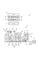
本実施形態の自動変速機3を備える車両1の概略構成について、図1に沿って説明する。車両1は、内燃エンジン2と、自動変速機3と、不図示の車輪と、油圧制御装置5と、ECU6とを備えている。内燃エンジン2は、例えばガソリンエンジンやディーゼルエンジン等の内燃機関であり、自動変速機3に連結されている。
A schematic configuration of a
自動変速機3は、入力軸30と、発進装置10と、変速機構(動力伝達装置)31と、不図示のカウンタシャフト部及びディファレンシャル部と、これらを収容するケース32とを備えている。自動変速機3の入力軸30は、内燃エンジン2の回転軸20に駆動連結されている。
The
発進装置10は、トルクコンバータ11と、それをロックアップし得るロックアップクラッチ12とを備えている。トルクコンバータ11は、自動変速機3の入力軸30に接続されたポンプインペラ11aと、作動流体である油を介してポンプインペラ11aの回転が伝達されるタービンランナ11bと、それらの間に配置されると共にワンウェイクラッチ11dにより一方向に回転が規制されたステータ11cとを有している。タービンランナ11bは、入力軸30と同軸の変速機構31の入力軸34に接続されている。ロックアップクラッチ12は、係合によりフロントカバー12aと変速機構31の入力軸34とを直接係合し、トルクコンバータ11をロックアップした状態にする。
The
変速機構31には、トルクコンバータ11を介して内燃エンジン2からの回転が伝達される入力軸34aが備えられており、入力軸34aの同軸上の後方側に接続された中心軸34bが備えられている。即ち、本自動変速機3においては、入力軸34aと中心軸34bとによって広義としての入力軸34が構成されている。変速機構31は、入力軸34上において、複数の回転要素を有する減速用のプラネタリギヤDPと、複数の回転要素を有する変速用のプラネタリギヤユニットPUと、が備えられている。また、変速機構31は、第1〜第4のクラッチC1〜C4と、第1及び第2のブレーキB1,B2とを備えている。これらの複数の係合要素は、ロックアップクラッチ12から後述するカウンタギヤ35までの動力伝達経路上に設けられ、油圧の給排により係脱し、同時係合する組み合わせにより複数の変速段を選択的に形成可能である。
The
プラネタリギヤDPは、入力回転を減速した減速回転を出力する減速用のプラネタリギヤであり、第1のサンギヤS1、第1のキャリヤCR1、第1のリングギヤR1を備えており、第1のキャリヤCR1に、第1のサンギヤS1に噛合するピニオンP2及び第1のリングギヤR1に噛合するピニオンP1を互いに噛合する形で有している所謂ダブルピニオンプラネタリギヤである。 The planetary gear DP is a planetary gear for reduction that outputs a reduced rotation obtained by reducing the input rotation, and includes a first sun gear S1, a first carrier CR1, and a first ring gear R1, and the first carrier CR1 includes This is a so-called double pinion planetary gear having a pinion P2 meshing with the first sun gear S1 and a pinion P1 meshing with the first ring gear R1 in mesh with each other.
一方、プラネタリギヤユニットPUは、4つの回転要素を有し、入力回転及び減速回転を選択的に入力して変速した出力回転を出力する変速用のプラネタリギヤユニットであり、4つの回転要素として第2のサンギヤS2、第3のサンギヤS3、第2のキャリヤCR2、第2のリングギヤR2を有し、第2のキャリヤCR2に、第2のサンギヤS2及び第2のリングギヤR2に噛合するロングピニオンP3と、第3のサンギヤS3に噛合するショートピニオンP4とを互いに噛合する形で有している所謂ラビニヨ型プラネタリギヤである。 On the other hand, the planetary gear unit PU has four rotating elements, and is a shifting planetary gear unit that selectively inputs the input rotation and the reduced rotation and outputs the output rotation that has been shifted. A long pinion P3 having a sun gear S2, a third sun gear S3, a second carrier CR2, a second ring gear R2, and meshing with the second sun gear S2 and the second ring gear R2; This is a so-called Ravigneaux type planetary gear having a short pinion P4 that meshes with the third sun gear S3 so as to mesh with each other.
プラネタリギヤDPの第1のサンギヤS1は、ケース32に対して回転が固定されている。また、第1のキャリヤCR1は、入力軸34に接続されて、入力軸34の回転と同回転(以下、入力回転という)になっていると共に、第4のクラッチC4に接続されている。更に、第1のリングギヤR1は、固定された第1のサンギヤS1と入力回転する第1のキャリヤCR1とにより、入力回転が減速された減速回転になると共に、第1のクラッチC1及び第3のクラッチC3に接続されている。
The rotation of the first sun gear S <b> 1 of the planetary gear DP is fixed with respect to the
プラネタリギヤユニットPUの第2のサンギヤS2は、第1のブレーキB1に接続されてケース32に対して固定自在となっていると共に、第4のクラッチC4及び第3のクラッチC3に接続されて、第4のクラッチC4を介して第1のキャリヤCR1の入力回転が、第3のクラッチC3を介して第1のリングギヤR1の減速回転が、それぞれ入力自在となっている。また、第3のサンギヤS3は、第1のクラッチC1に接続されており、第1のリングギヤR1の減速回転が入力自在となっている。
The second sun gear S2 of the planetary gear unit PU is connected to the first brake B1 and can be fixed to the
更に、第2のキャリヤCR2は、入力軸34の回転が入力される第2のクラッチC2に接続されて、第2のクラッチC2を介して入力回転が入力自在となっており、また、第2のキャリヤCR2は、第2のブレーキB2及びワンウェイクラッチ(OWC)F1に接続されて、第2のブレーキB2又はワンウェイクラッチF1を介して回転が固定自在となっている。そして、第2のリングギヤR2は、ケース32に固定されたセンタサポート部材36(図3参照)に対して回転自在に支持されたカウンタギヤ35に接続されている。カウンタギヤ35は、いずれも不図示のカウンタシャフト部からディファレンシャル部を介して車輪に駆動連結されている。
Further, the second carrier CR2 is connected to the second clutch C2 to which the rotation of the
油圧制御装置(V/B)5は、例えばバルブボディにより構成されており、オイルポンプから供給された油圧からライン圧等を生成し、ECU6からの制御信号に基づいて各第1〜第4のクラッチC1〜C4と、第1及び第2のブレーキB1,B2と、ロックアップクラッチ12とをそれぞれ制御する係合圧としての油圧を給排可能になっている。
The hydraulic control device (V / B) 5 is constituted by, for example, a valve body, generates a line pressure or the like from the hydraulic pressure supplied from the oil pump, and each of the first to fourth based on a control signal from the
ECU6は、例えば、CPU61と、処理プログラムを記憶するROM62と、データを一時的に記憶するRAM63と、入出力ポート(I/F)64とを備えている。ECU6は、油圧制御装置5を電気的に制御することにより自動変速機3を制御可能である。ECU6には、例えば、車速を検出するためのセンサや、不図示のアクセルペダルの踏込量を検出するためのセンサが連結されている。ECU6は、例えば、車速やアクセルペダルの踏込量等に応じて、自動変速機3の変速段を設定し、その変速段を形成するために、例えば、各第1〜第4のクラッチC1〜C4と、第1及び第2のブレーキB1,B2とを係脱するための制御信号を出力する。
The
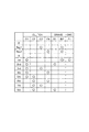
以上のように構成された変速機構31は、カウンタギヤ35からの出力について、図1のスケルトン図に示す各第1のクラッチC1〜第4のクラッチC4、第1のブレーキB1及び第2のブレーキB2が、図2の係合表に示す組み合わせで係脱されることにより、前進1速段(1st)〜前進8速段(8th)、及び後進1速段(Rev1)〜後進2速段(Rev2)が達成される。
With respect to the output from the
次に、本実施形態に係る自動変速機3の変速機構31について、図3に沿って説明する。ケース32(図1参照)の内側には、ケース32に固定されたセンタサポート部材36が設けられており、センタサポート部材36の前方にはプラネタリギヤDPが配置され、後方にはプラネタリギヤユニットPUが配置されている。
Next, the
プラネタリギヤDPは、入力軸34a上に、第1のキャリヤCR1と、第1のリングギヤR1と、第1のサンギヤS1とが配置されて構成されている。第1のサンギヤS1は、入力軸34に対して回転自在に支持されている。第1のキャリヤCR1は、キャリヤプレートによって第1のピニオンシャフトPS1及び不図示の第2のピニオンシャフトを支持している。また、各ピニオンシャフトPS1が、それぞれピニオンP1,P2(図1参照)を回転自在に支持しており、第1のピニオンP1は外周側において第1のリングギヤR1と噛合すると共に第2のピニオンP2と噛合し、第2のピニオンP2は内周側において第1のサンギヤS1と噛合している。第1のキャリヤCR1は、入力軸34aに対して固定して支持されており、入力軸34aと一体回転する。
The planetary gear DP is configured by arranging a first carrier CR1, a first ring gear R1, and a first sun gear S1 on an
第1のリングギヤR1の外周側には、クラッチハブ40が一体的に形成されている。クラッチハブ40は、外周部の前部に第3のクラッチC3の複数の内摩擦板50と係合するスプライン40sを有すると共に、外周部の後部に第1のクラッチC1の複数の内摩擦板と係合するスプラインを有している。
A
クラッチハブ40の後部の外周側には、第1のクラッチC1を挟んでクラッチドラム41が設けられている。クラッチドラム41は、内周部に第1のクラッチC1の複数の外摩擦板と係合するスプラインを有している。第1のクラッチC1の後方には、第1のクラッチC1を係脱可能な油圧サーボ42が設けられている。尚、油圧サーボ42の構成としては、既知あるいは新規の適宜な構成を適用可能であり、詳細な説明は省略する。クラッチドラム41の後部は、中心軸34bに対して回転可能に支持されると共に、第3のサンギヤS3にスプライン係合されて一体回転する。
A
第1のキャリヤCR1には、ドラム部43が一体化して固定されている。ドラム部43は、外周側に第4のクラッチC4の複数の内摩擦板と係合するスプラインを有している。ドラム部43の外周側には、第4のクラッチC4を挟んで回転部材(第2の部材)44が設けられている。回転部材44は、入力軸34aに回転可能に支持された内回転部材44aと、内回転部材44aの外周側に配置され内回転部材44aに対して一体化されたアルミニウム製の外回転部材44bとを有している。
The drum portion 43 is integrally fixed to the first carrier CR1. The drum portion 43 has splines that engage with the plurality of inner friction plates of the fourth clutch C4 on the outer peripheral side. A rotating member (second member) 44 is provided on the outer peripheral side of the drum portion 43 with the fourth clutch C4 interposed therebetween. The rotating
外回転部材44bは、内周部に第3のクラッチC3の複数の外摩擦板51と係合するスプライン44sを有している。このスプライン44sは、歯部(第2の歯部)44t及び溝部(第2の溝部)44gが交互に配置されて形成されている(図6参照)。複数の外摩擦板51のうちで最も後方側に配置された外摩擦板51の後方側には、スプライン44sに固定されたストッパ52が設けられている。
The outer rotating
第3のクラッチC3の前方には、第3のクラッチC3を係脱可能な油圧サーボ46が設けられている。尚、油圧サーボ46の構成としては、既知あるいは新規の適宜な構成を適用可能であり、詳細な説明は省略する。内回転部材44aは、内周部に第4のクラッチC4の複数の外摩擦板と係合するスプラインを有している。第4のクラッチC4の前方には、第4のクラッチC4を係脱可能な油圧サーボ45が設けられている。尚、油圧サーボ45の構成としては、既知あるいは新規の適宜な構成を適用可能であり、詳細な説明は省略する。
A
クラッチドラム41の外周側には、回転部材44と同軸上に鉄製の回転ドラム(第1の部材)47が設けられている。回転ドラム47の前端部は、回転部材44に対して連結部7においてスプライン係合により一体回転可能に連結されている。連結部7の詳細な構成については、後述する。また、回転ドラム47及び回転部材44は、ドラムサンギヤインプットサブアッシーを構成している。
On the outer peripheral side of the
回転ドラム47は、外周部の前部に第1のブレーキB1の複数の内摩擦板53と係合するスプライン(第1のスプライン)47sを有している。このスプライン47sは、回転部材44のスプライン44sに係合する歯部(第1の歯部)47t及び溝部(第1の溝部)47gが交互に配置されて形成されている(図4参照)。また、スプライン47sは、スプライン44sの内側に配置されている。
The
第1のブレーキB1の後方には、第1のブレーキB1を係脱可能な油圧サーボ48が設けられている。尚、油圧サーボ48の構成としては、既知あるいは新規の適宜な構成を適用可能であり、詳細な説明は省略する。回転ドラム47の前部の外周側には、第1のブレーキB1を挟んでセンタサポート部材36が位置している。センタサポート部材36の前部の内周側には、第1のブレーキB1の複数の外摩擦板54と係合するスプライン36sが形成されている。回転ドラム47の後部は、中心軸34bに対して回転可能に支持されると共に、第2のサンギヤS2にスプライン係合されて一体回転する。
A
プラネタリギヤユニットPUは、中心軸34b上に、第2のキャリヤCR2と、第2のリングギヤR2と、第2のサンギヤS2と、第3のサンギヤS3とが配置されて構成されている。第2のサンギヤS2及び第3のサンギヤS3は、入力軸34に対して回転自在に支持されている。第2のキャリヤCR2は、キャリヤプレートによって不図示の複数のピニオンシャフトを支持している。これらのピニオンシャフトが、ピニオンP3,P4(図1参照)を回転自在に支持している。第2のリングギヤR2の前方には、カウンタギヤ35がスプライン係合により連結されている。カウンタギヤ35は、不図示のカウンタドリブンギヤに噛合している。カウンタギヤ35は、センタサポート部材36に回転自在に支持されている。
The planetary gear unit PU is configured by arranging a second carrier CR2, a second ring gear R2, a second sun gear S2, and a third sun gear S3 on a
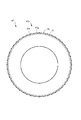
次に、回転ドラム47と回転部材44とを連結する連結部7の構成について、詳細に説明する。図4に示すように、連結部7には、複数の付勢ばね(付勢部)70と、付勢ばね70を回転ドラム47に固定するリング部(固定部)71とが設けられている。複数の付勢ばね70は、図5に示すように周方向に均等に配置され、図6Bにおいて矢印で示すように回転ドラム47のスプライン47sと回転部材44のスプライン44sとを径方向に離間する方向に付勢する。リング部71は、付勢ばね70を回転ドラム47に固定する。リング部71は、少なくとも、回転ドラム47のスプライン47sと回転部材44のスプライン44sが係合されない状態において、付勢ばね70を回転ドラム47に固定する。但し、本実施形態では、リング部71は、回転ドラム47のスプライン47sと回転部材44のスプライン44sが係合された状態においても、付勢ばね70を回転ドラム47に固定している。
Next, the configuration of the connecting
図4及び図6Aに示すように、各歯部47tは、歯部47tの前端から後方に向けて軸方向に沿った形状の凹部47aと、周方向に沿って形成され、各凹部47aの後端部に連通されている周溝部47bとを有している。凹部47a及び周溝部47bは、スプライン47sの形成後に切削加工あるいはプレス加工により形成することができる。
As shown in FIGS. 4 and 6A, each
凹部47aは、回転ドラム47の径方向の外周側を開口して形成され、付勢ばね70をスプライン44sに対向させて溝部44gの底面に接触させるように収容する。周溝部47bは、回転ドラム47の径方向の外周側を開口して形成され、リング部71を収容する。周溝部47bの深さは、例えば、リング部71が歯部47tの歯先面から突出しないものとしている。また、周溝部47bは、歯部47tにのみ形成され、溝部47gには形成されていない。図6Bに示すように、周溝部47bは、スプライン44sに対して軸方向にオフセットした位置に配置されている。即ち、スプライン47sの溝部47gでは、リング部71は露出しているが、スプライン44sはリング部71に達しない範囲で連結されるので、スプライン44sの歯部44tとリング部71とが干渉することは防止される。
The
付勢ばね70は、例えば鋼板からなる板ばねであり、図6Bに示すように、凹部47aに収容された状態で回転ドラム47と回転部材44とがスプライン係合した際に、凹部47aの底面と回転部材44のスプライン44sの溝部44gの底面との間で、回転ドラム47の径方向に広がる方向に付勢する。付勢ばね70は、各歯部47tに設けられることで、周方向に均等に配置されている。尚、鋼板からなる付勢ばね70の回転部材44に対する接触部は丸みのある形状とされ、アルミニウム製である回転部材44の摩耗を極力抑制することができる。
The urging
リング部71は鋼製で、全ての付勢ばね70と一体形成により一体化されている。リング部71は、各周溝部47bに収容されて周方向に亘って設けられ、回転ドラム47に外周側から巻き付けられることで付勢ばね70を回転ドラム47に固定する。リング部71の周方向の両端部には、互いに係合して固定される不図示の係合部が設けられている。係合部は、例えば爪形状であり、両端部同士が係合により周方向及び軸方向に固定される構成であることが望ましい。
The
上述した回転ドラム47に付勢ばね70及びリング部71を取り付ける際には、各付勢ばね70を凹部47aに収容し、リング部71を周溝部47bに巻き付けて固定する。この時、リング部71が回転ドラム47に固定されるため、リング部71と一体形成された付勢ばね70もまた回転ドラム47に固定される。これにより、回転ドラム47に回転部材44を組み付ける前であっても、付勢ばね70は回転ドラム47に固定されて脱落が防止されるので、部材の取り回しが容易であり、組立時の作業性を向上することができる。
When attaching the urging
また、上述した回転ドラム47に付勢ばね70及びリング部71を取り付けた後、回転部材44を連結する際は、スプライン47s,44s同士を係合するように回転ドラム47と回転部材44を軸方向に係合する。このとき、回転ドラム47と回転部材44とは、スプライン47s,44s同士が係合する全ての位相で係合させることができる。このため、付勢ばね70及びリング部71が設けられていない場合と連結作業は同様であるので、作業性の悪化を招くことはない。
In addition, after attaching the urging
尚、図6Bに示すように、回転ドラム47に回転部材44を係合した際に、付勢ばね70は回転ドラム47の径方向に圧縮される。このとき、付勢ばね70は軸方向に伸長するが、付勢ばね70の先端が、例えばスプライン44sのストッパ52に干渉しないように、凹部47aあるいは付勢ばね70の長さなどを設定する。
6B, when the
以上説明したように、本実施形態の自動変速機3によると、各スプライン47s,44sを径方向に離間する方向に付勢する複数の付勢ばね70が、周方向に均等に配置されているので、各スプライン47s,44sは互いに軸心が一致して芯出しされる。このため、各スプライン47s,44sの偏心の発生を抑制することができるので、回転ドラム47及び回転部材44の間において、回転時の偏心に起因する摩耗の発生を抑制することができる。
As described above, according to the
また、少なくとも回転ドラム47及び回転部材44の組み付け前、即ち、各スプライン47s,44sが係合されない状態において、リング部71が付勢ばね70を回転ドラム47に固定するので、付勢ばね70の脱落を防止することができる。このため、回転ドラム47及び回転部材44を組み付ける際の作業性を向上することができる。
Further, since the
ここで、歯部47tと溝部44gとの間は狭いために、そのままでは付勢ばね70を設けることはできない。これに対し、本実施形態の自動変速機3によると、歯部47tの外周側に凹部47aを形成することで、付勢ばね70を収容することができる。これにより、スプライン47s,44sの歯数を減らすことがなく、各歯部47t,44tの面圧を確保することができる。また、面圧を維持できるので、多数の歯部47tに付勢ばね71を設けることができ、回転ドラム47及び回転部材44の芯出しを容易にすることができる。
Here, since the space between the
また、回転ドラム47及び回転部材44は、ドラムサンギヤインプットサブアッシーを構成しており、互いの間の反力で回転軸の傾きを発生する虞がある。これに対し、本実施形態の自動変速機3によると、回転ドラム47及び回転部材44の連結部7に付勢ばね70を設けているので、回転ドラム47及び回転部材44の回転軸の傾きを防止して、スプライン47s,44sの摩耗を抑制することができる。また、N−R変速時において、ドラムサンギヤインプットサブアッシーの起き上がりによる変速ショックを抑えることができる。
Further, the
また、本実施形態の自動変速機3によると、リング部71は全周に亘って巻き付けられているので、1つの部材で全ての付勢ばね70を固定することができる。しかも、リング部71を回転ドラム47に巻き付けるだけで付勢ばね70を固定することができるので、取り付け時の作業性を損なうことを防止できる。
Moreover, according to the
また、本実施形態の自動変速機3によると、1つのリング部71に対し、複数の付勢ばね70が一体化されているので、回転ドラム47に1つのリング部71を固定する作業で複数の付勢ばね70を固定することができ、作業性を向上することができる。また、回転ドラム47への取り付け後に一部の付勢ばね70が脱落してしまうことはなく、付勢ばね70の紛失を抑制することができる。
Further, according to the
尚、上述した本実施形態においては、スプライン47sの全ての歯部47tに付勢ばね70を設けた場合について説明したが、これには限られない。例えば、周方向の複数箇所に等間隔に配置するなど、均等配置であれば、スプライン47s,44sの芯出しを行うことができる。また、付勢ばね70を均等配置する配置箇所の数としては、8箇所以上が好ましい。
In addition, in this embodiment mentioned above, although the case where the urging | biasing
また、本実施形態においては、リング部71は全周に亘って巻き付けられているが、これには限られない。例えば、C形状のリングばねが回転ドラム47に巻き付けられるようにしてもよい。
Moreover, in this embodiment, although the
また、本実施形態においては、付勢ばね70とリング部71とを一体形成されたものとしたが、これには限られない。例えば、付勢ばね70とリング部71とを別個に形成し、接着や溶接などにより一体化してもよい。あるいは、付勢ばね70とリング部71とは別体のままで、リング部71が付勢ばね70を凹部47aに押さえ付けて固定するようにしてもよい。
In the present embodiment, the urging
また、本実施形態においては、動力伝達装置を自動変速機3の変速機構31に適用した場合について説明したが、これには限られない。この動力伝達装置は、動力を伝達する第1の部材と第2の部材との全般に広く適用することができる。
In the present embodiment, the case where the power transmission device is applied to the
<第2の実施形態>
次に、自動変速機3の第2の実施形態を、図7A乃至図10に沿って説明する。本実施形態では、回転ドラム47と回転部材44との連結部107において、固定部171は、付勢ばね(付勢部)170に一体化して設けられ、回転ドラム47の一部を挟持して固定されることで付勢ばね170を回転ドラム47に固定する点で、第1の実施形態と構成を異にする。これ以外の構成については、第1の実施形態と同様であるので、符号を同じくして詳細な説明を省略する。
<Second Embodiment>
Next, a second embodiment of the
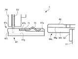
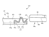
本実施形態では、図7A及び図7Bに示すように、付勢ばね170は、回転ドラム47のスプライン47sの軸方向を長手方向とする鋼製の板ばねである。固定部171は、付勢ばね170の軸方向両端部に一体化して形成され、後端部に一体化された後側固定部172と、前端部に一体化された前側固定部173とを有している。後側固定部172及び前側固定部173は、いずれも付勢ばね170の長手方向に対して回転ドラム47の径方向の中心に向けて略直角に折り曲げられている。
In this embodiment, as shown in FIGS. 7A and 7B, the biasing
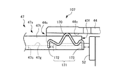
図8に示すように、スプライン47sは、溝部47gを径方向に貫通する油孔(係合部)47cを有している。後側固定部172は、油孔47cの前側近傍の側面を係合部として係合している。前側固定部173は、スプライン47sの軸方向前側の端面(係合部)47fに係合している。後側固定部172が油孔47cの側面に係合すると共に、前側固定部173が端面47fに係合することで、付勢ばね170は、油孔47cと端面47fとの間の溝部47gを軸方向に挟持して回転ドラム47に固定される。
As shown in FIG. 8, the
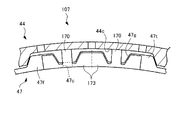
図9A及び図9Bに示すように、前側固定部173は、周方向に隣り合う前側固定部173に連結されている。また、前側固定部173は、スプライン47sの端面47fの輪郭に沿った形状に形成されている。これにより、前側固定部173は、1個単独で設けられる場合に比べて広い受圧面積で端面47fに接することができるので、付勢ばね170の固定の安定化を図ることができる。本実施形態では、2つの付勢ばね170の前側固定部173を連結した組み合わせとしているが、これには限られない。但し、広い受圧面積による固定の安定化のために、2つ以上の前側固定部173を連結することが好ましい。
As shown in FIGS. 9A and 9B, the front
本実施形態では、2つの付勢ばね170の前側固定部173を連結した組み合わせを、図10に示すように、周方向の8箇所に等間隔に配置している。このように付勢ばね170を周方向に均等配置することにより、スプライン47s,44sの芯出しを行うことができる。付勢ばね170の配置箇所の数としては、8箇所には限られないが、4箇所以上で均等配置であることが好ましい。
In this embodiment, the combination which connected the front side fixing |
回転部材44のスプライン44sは、付勢ばね170に対向する部位に欠歯部44cを有している。これにより、回転ドラム47のスプライン47sの溝部47gに付勢ばね170を固定した状態であっても、付勢ばね170が対向するスプライン44sの歯部44tに干渉することを防止できる。尚、欠歯部44cは、例えば、スプライン44sの形成後、付勢ばね170に対向する歯部44tを切削することにより形成する。
The
上述した回転ドラム47に付勢ばね170を取り付ける際には、例えば、後側固定部172を油孔47cの側面に係合し、前側固定部173を前側に引っ張って端面47fに引っ掛ける。これにより、固定部171は、回転ドラム47の一部、即ち油孔47cと端面47fとの間を挟持して固定されることで付勢ばね170を回転ドラム47に固定する。これにより、回転ドラム47に回転部材44を組み付ける前であっても、付勢ばね170は回転ドラム47に固定されて脱落が防止されるので、部材の取り回しが容易であり、組立時の作業性を向上することができる。
When the urging
また、上述した回転ドラム47に付勢ばね170を取り付けた後、回転部材44を連結する際は、スプライン47s,44s同士を係合するように回転ドラム47と回転部材44を軸方向に係合する。ここで、回転ドラム47と回転部材44とは、付勢ばね170の設置位置とスプライン44sの欠歯部44cとが一致するように係合する。付勢ばね170の設置位置とスプライン44sの欠歯部44cとを一致させることにより、付勢ばね170が設けられていない通常の構成と同様に連結作業を行うことができる。
Further, after the
尚、図7Bに示すように、回転ドラム47に回転部材44を係合した際に、付勢ばね170は回転ドラム47の径方向に圧縮される。このとき、付勢ばね170は軸方向に伸長するが、付勢ばね170の軸方向の可動範囲は、後側固定部172が油孔47cの前側近傍の側面に当接する位置から、前側固定部173が端面47fに当接する位置までの間である。ここで、付勢ばね170が最も前側に突出して後側固定部172が油孔47cの前側近傍の側面に当接した際に、前側固定部173がスプライン44sのストッパ52に干渉しないように、各部の寸法を設定する。
7B, when the rotating
以上説明したように、本実施形態の自動変速機3によっても、各スプライン47s,44sを径方向に離間する方向に付勢する複数の付勢部170が、周方向に均等に配置されているので、各スプライン47s,44sは互いに軸心が一致して芯出しされる。このため、各スプライン47s,44sの偏心の発生を抑制することができるので、回転ドラム47及び回転部材44の間において、回転時の偏心に起因する摩耗の発生を抑制することができる。
As described above, also in the
また、回転ドラム47及び回転部材44の組み付け前、即ち、各スプライン47s,44sが係合されない状態において、固定部171によって付勢ばね170が回転ドラム47に固定されるので、付勢ばね170の脱落を防止することができる。このため、回転ドラム47及び回転部材44を組み付ける際の作業性を向上することができる。
Further, before the
また、本実施形態の自動変速機3によると、固定部171は、付勢ばね170に一体化して設けられ、回転ドラム47の一部を挟持して固定されることで付勢ばね170を回転ドラム47に固定するので、取り付け作業を容易に行うことができ、作業性の低下を招くことなく付勢ばね170を設けることができる。
Further, according to the
また、本実施形態の自動変速機3によると、付勢ばね170は、スプライン47sの軸方向を長手方向とする板ばねであり、固定部171は、付勢ばね170の軸方向両端部に一体化して形成されている。また、スプライン47sは、溝部47gにおいて、軸方向両端部に形成された固定部171がそれぞれ係合可能であり、係合により固定部171が溝部47gを軸方向に挟持することで、付勢ばね170を回転ドラム47に固定する油孔47c及び端面47fを有する。これにより、付勢ばね170の取り付け作業を容易に行うことができ、作業性の低下を招くことなく付勢ばね170を設けることができる。
Further, according to the
また、本実施形態の自動変速機3によると、固定部171は、周方向に隣り合う固定部171に連結されている。このため、固定部171が1個単独で設けられる場合に比べて広い受圧面積で端面47fに接することができるので、付勢ばね170の固定の安定化を図ることができる。
Further, according to the
尚、本実施形態の自動変速機3では、固定部171は、油孔47cと端面47fとを挟持する構成としたが、これには限られない。例えば、1本の溝部47gに配置された複数の油孔47c同士を挟持する構成としても良い。この場合、固定部171は、付勢ばね170に一体化して設けられ、回転ドラム47の一部を挟持して固定されることで付勢ばね170を回転ドラム47に固定したものとする。この構成によっても、付勢ばね170の取り付け作業を容易に行うことができ、作業性の低下を招くことなく付勢ばね170を設けることができる。
In addition, in the
尚、第1及び第2の実施形態は、以下の構成を少なくとも備える。第1及び第2の実施形態の動力伝達装置(31)では、第1の歯部(47t)及び第1の溝部(47g)が交互に配置された第1のスプライン(47s)を有する第1の部材(47)と、前記第1の部材(47)と同軸上に配置され、前記第1のスプライン(47s)に係合する第2の歯部(44t)及び第2の溝部(44g)が交互に配置された第2のスプライン(44s)を有し、前記第1の部材(47)と一体回転可能な第2の部材(44)と、周方向に均等に配置され、前記第1及び第2のスプライン(47s,44s)を径方向に離間する方向に付勢する複数の付勢部(70,170)と、前記付勢部(70,170)を前記第1の部材(47)に固定する固定部(71,171)と、を備える。この構成によれば、第1及び第2のスプライン(47s,44s)を径方向に離間する方向に付勢する複数の付勢部(70,170)が、周方向に均等に配置されているので、第1及び第2のスプライン(47s,44s)は互いに軸心が一致して芯出しされる。このため、第1及び第2のスプライン(47s,44s)の偏心の発生を抑制することができるので、第1の部材(47)及び第2の部材(44)の間において、回転時の偏心に起因する摩耗の発生を抑制することができる。また、少なくとも第1及び第2の部材(47,44)の組み付け前、即ち、第1及び第2のスプライン(47s,44s)が係合されない状態において、固定部(71,171)が付勢部(70,170)を第1の部材(47)に固定できるで、付勢部(70,170)の脱落を防止することができる。このため、第1及び第2の部材(47,44)を組み付ける際の作業性を向上することができる。 In addition, 1st and 2nd embodiment is provided with the following structures at least. In the power transmission device (31) of the first and second embodiments, the first spline (47s) in which the first tooth portions (47t) and the first groove portions (47g) are alternately arranged is provided. Member (47), a second tooth portion (44t) and a second groove portion (44g) which are arranged coaxially with the first member (47) and engage with the first spline (47s). Have second splines (44s) arranged alternately, second members (44) that can rotate integrally with the first members (47), and evenly arranged in the circumferential direction, the first And a plurality of urging portions (70, 170) for urging the second splines (47s, 44s) in the radially separating direction, and the urging portions (70, 170) as the first member (47). ) And fixing portions (71, 171) to be fixed. According to this structure, the several urging | biasing part (70,170) which urges | biases the 1st and 2nd spline (47s, 44s) to the direction spaced apart to radial direction is arrange | positioned equally in the circumferential direction. Therefore, the first and second splines (47s, 44s) are centered with their axes aligned. For this reason, since the occurrence of eccentricity of the first and second splines (47s, 44s) can be suppressed, the eccentricity during rotation between the first member (47) and the second member (44). It is possible to suppress the occurrence of wear due to the above. Further, at least before the first and second members (47, 44) are assembled, that is, in a state where the first and second splines (47s, 44s) are not engaged, the fixing portions (71, 171) are biased. Since the portion (70, 170) can be fixed to the first member (47), the urging portion (70, 170) can be prevented from falling off. For this reason, workability at the time of assembling the first and second members (47, 44) can be improved.
また、第1の実施形態の動力伝達装置(31)では、前記第1のスプライン(47s)は前記第2のスプライン(44s)の内側に配置され、前記第1の歯部(47t)は、前記付勢部(70)を前記第2のスプライン(44s)に対向させて収容する凹部(47a)を有する。この構成によれば、第1のスプライン(47s)及び第2のスプライン(44s)の歯数を減らすことがなく、各歯部(47t,44t)の面圧を確保することができる。また、面圧を維持できるので、多数の歯部に付勢部(70)を設けることができ、第1の部材(47)及び第2の部材(44)の芯出しを容易にすることができる。 In the power transmission device (31) of the first embodiment, the first spline (47s) is disposed inside the second spline (44s), and the first tooth portion (47t) is The urging portion (70) has a recess (47a) for accommodating the urging portion (70) so as to face the second spline (44s). According to this configuration, the surface pressure of each tooth portion (47t, 44t) can be ensured without reducing the number of teeth of the first spline (47s) and the second spline (44s). Further, since the surface pressure can be maintained, the urging portions (70) can be provided in a large number of tooth portions, and the first member (47) and the second member (44) can be easily centered. it can.
また、第1の実施形態の動力伝達装置(31)では、1つの前記固定部(71)に対して複数の前記付勢部(70)が一体化され、前記固定部(71)は、周方向に亘って設けられ、前記第1の部材(47)に外周側から巻き付けられることで前記付勢部(70)を前記第1の部材(47)に固定する。この構成によれば、固定部(71)を第1の部材(47)に巻き付けるだけで付勢部(70)を固定することができるので、取り付け時の作業性を損なうことを防止できる。また、第1の部材(47)に1つの固定部(71)を固定する作業で複数の付勢部(70)を固定することができ、作業性を向上することができる。しかも、固定部(71)を第1の部材(47)に取り付けた後に一部の付勢部(70)が脱落してしまうことはなく、付勢部(70)の紛失を抑制することができる。 Further, in the power transmission device (31) of the first embodiment, a plurality of the urging portions (70) are integrated with the one fixing portion (71), and the fixing portion (71) It is provided over the direction, and the urging portion (70) is fixed to the first member (47) by being wound around the first member (47) from the outer peripheral side. According to this configuration, since the urging portion (70) can be fixed simply by winding the fixing portion (71) around the first member (47), it is possible to prevent the workability during attachment from being impaired. In addition, the plurality of urging portions (70) can be fixed by the operation of fixing one fixing portion (71) to the first member (47), and workability can be improved. Moreover, after the fixing portion (71) is attached to the first member (47), a part of the urging portion (70) does not fall off, and the loss of the urging portion (70) is suppressed. it can.
また、第1の実施形態の動力伝達装置(31)では、前記第1のスプライン(47s)は、周方向に沿って形成された、前記固定部(71)を収容する周溝部(47b)を有し、前記周溝部(47b)は前記凹部(47a)と連通されている。この構成によれば、取り付け後の固定部(71)が軸方向に移動してしまうことを防止できる。 In the power transmission device (31) of the first embodiment, the first spline (47s) includes a circumferential groove portion (47b) that is formed along the circumferential direction and accommodates the fixing portion (71). The circumferential groove (47b) communicates with the recess (47a). According to this structure, it can prevent that the fixing | fixed part (71) after attachment moves to an axial direction.
また、第1の実施形態の動力伝達装置(31)では、前記周溝部(47b)は、前記第2のスプライン(44s)に対して軸方向にオフセットした位置に配置されている。この構成によれば、第2のスプライン(44s)は、固定部(71)に達しない範囲で連結されるので、第2のスプライン(44s)の第2の歯部(44t)と固定部(71)とが干渉することは防止される。 In the power transmission device (31) of the first embodiment, the circumferential groove portion (47b) is disposed at a position offset in the axial direction with respect to the second spline (44s). According to this configuration, since the second spline (44s) is connected within a range not reaching the fixing portion (71), the second tooth portion (44t) of the second spline (44s) and the fixing portion ( 71) are prevented from interfering with each other.
また、第2の実施形態の動力伝達装置(31)では、前記付勢部(170)は、前記第1のスプライン(47s)の軸方向を長手方向とする板ばねであり、前記固定部(171)は、前記付勢部(170)の軸方向両端部に一体化して形成され、軸方向一端部においては周方向に隣り合う前記固定部(171)に連結され、前記第1のスプライン(47s)は、前記第1の溝部(47g)において、前記軸方向両端部に形成された前記固定部(171)がそれぞれ係合可能であり、係合により前記固定部(171)が前記第1の溝部(47g)を軸方向に挟持することで、前記付勢部(170)を前記第1の部材(47)に固定する係合部(47c,47f)を有する。この構成によれば、付勢部(170)の取り付け作業を容易に行うことができ、作業性の低下を招くことなく付勢部(170)を設けることができる。また、固定部(171)は、1個単独で設けられる場合に比べて広い受圧面積で係合部(47f)に接することができるので、付勢部(170)の固定の安定化を図ることができる。 In the power transmission device (31) of the second embodiment, the urging portion (170) is a leaf spring whose longitudinal direction is the axial direction of the first spline (47s), and the fixing portion ( 171) is integrally formed at both axial ends of the biasing portion (170), and is connected to the fixing portion (171) adjacent in the circumferential direction at one axial end portion, and the first spline ( 47s), in the first groove portion (47g), the fixing portions (171) formed at both ends in the axial direction can be respectively engaged, and the fixing portion (171) is engaged with the first groove portion by the engagement. The engaging portion (47c, 47f) that fixes the biasing portion (170) to the first member (47) by sandwiching the groove portion (47g) in the axial direction. According to this configuration, the urging unit (170) can be easily attached, and the urging unit (170) can be provided without deteriorating workability. Moreover, since the fixing | fixed part (171) can contact the engaging part (47f) with a large pressure receiving area compared with the case where it is provided individually, the fixation of the urging part (170) can be stabilized. Can do.
また、第2の実施形態の動力伝達装置(31)では、前記第2のスプライン(44s)は、前記付勢部(170)に対向する部位に欠歯部(44c)を有する。この構成によれば、付勢部(170)が、対向する第2のスプライン(44s)の歯部(44t)と干渉することなく、第1のスプライン(47s)と第2のスプライン(44s)とを連結することができる。 Moreover, in the power transmission device (31) of the second embodiment, the second spline (44s) has a missing tooth portion (44c) at a portion facing the biasing portion (170). According to this configuration, the urging portion (170) does not interfere with the teeth (44t) of the opposing second spline (44s), and the first spline (47s) and the second spline (44s). Can be linked.
また、第2の実施形態の動力伝達装置(31)では、前記係合部(47c,47f)は、前記第1の溝部(47g)を径方向に貫通する油孔(47c)の側面と、前記第1の部材(47)の軸方向の端面(47f)と、である。この構成によれば、既存の油孔(47c)及び端面(47f)を用いて付勢部(170)を固定することができるので、コストアップを抑えることができる。 Further, in the power transmission device (31) of the second embodiment, the engaging portion (47c, 47f) includes a side surface of the oil hole (47c) that penetrates the first groove portion (47g) in the radial direction, And an end face (47f) in the axial direction of the first member (47). According to this configuration, since the urging portion (170) can be fixed using the existing oil hole (47c) and the end surface (47f), an increase in cost can be suppressed.
31 変速機構(動力伝達装置)
44 回転部材(第2の部材)
44c 欠歯部
44g 第2の溝部
44s スプライン(第2のスプライン)
44t 第2の歯部
47 回転ドラム(第1の部材)
47a 凹部
47b 周溝部
47c 油孔(係合部)
47f 端面(係合部)
47g 溝部(第1の溝部)
47s スプライン(第1のスプライン)
47t 歯部(第1の歯部)
70,170 付勢ばね(付勢部)
71 リング部(固定部)
171 固定部
172 後側固定部(固定部)
173 前側固定部(固定部)
31 Transmission mechanism (power transmission device)
44 Rotating member (second member)
44c No-
44t
47a
47f End face (engagement part)
47g Groove (first groove)
47s spline (first spline)
47t tooth (first tooth)
70,170 Biasing spring (Biasing part)
71 Ring part (fixed part)
171
173 Front side fixing part (fixing part)
Claims (8)
前記第1の部材と同軸上に配置され、前記第1のスプラインに係合する第2の歯部及び第2の溝部が交互に配置された第2のスプラインを有し、前記第1の部材と一体回転可能な第2の部材と、
周方向に均等に配置され、前記第1及び第2のスプラインを径方向に離間する方向に付勢する複数の付勢部と、
前記付勢部を前記第1の部材に固定する固定部と、を備える動力伝達装置。 A first member having a first spline in which first teeth and first grooves are alternately arranged;
A first spline having a second spline arranged coaxially with the first member and having second teeth and second grooves alternately engaged with the first spline; A second member rotatable integrally with the second member;
A plurality of urging portions that are equally disposed in the circumferential direction and urge the first and second splines in a direction of separating in the radial direction;
And a fixing portion that fixes the biasing portion to the first member.
前記固定部は、前記付勢部の軸方向両端部に一体化して形成され、軸方向一端部においては周方向に隣り合う前記固定部に連結され、
前記第1のスプラインは、前記第1の溝部において、前記軸方向両端部に形成された前記固定部がそれぞれ係合可能であり、係合により前記固定部が前記第1の溝部を軸方向に挟持することで、前記付勢部を前記第1の部材に固定する係合部を有する請求項1に記載の動力伝達装置。 The biasing portion is a leaf spring whose longitudinal direction is the axial direction of the first spline,
The fixing portion is formed integrally with both end portions in the axial direction of the biasing portion, and is connected to the fixing portion adjacent in the circumferential direction at one end portion in the axial direction.
In the first spline, the fixing portions formed at both end portions in the axial direction can be engaged with each other in the first groove portion, and the fixing portion causes the first groove portion to extend in the axial direction by engagement. The power transmission device according to claim 1, further comprising an engaging portion that fixes the urging portion to the first member by clamping.
The power transmission device according to claim 6 or 7, wherein the engagement portion is a side surface of an oil hole that penetrates the first groove portion in a radial direction and an end surface in an axial direction of the first member.
Priority Applications (1)
| Application Number | Priority Date | Filing Date | Title |
|---|---|---|---|
| JP2016142688A JP2018013169A (en) | 2016-07-20 | 2016-07-20 | Power transmission device |
Applications Claiming Priority (1)
| Application Number | Priority Date | Filing Date | Title |
|---|---|---|---|
| JP2016142688A JP2018013169A (en) | 2016-07-20 | 2016-07-20 | Power transmission device |
Publications (1)
| Publication Number | Publication Date |
|---|---|
| JP2018013169A true JP2018013169A (en) | 2018-01-25 |
Family
ID=61020076
Family Applications (1)
| Application Number | Title | Priority Date | Filing Date |
|---|---|---|---|
| JP2016142688A Pending JP2018013169A (en) | 2016-07-20 | 2016-07-20 | Power transmission device |
Country Status (1)
| Country | Link |
|---|---|
| JP (1) | JP2018013169A (en) |
-
2016
- 2016-07-20 JP JP2016142688A patent/JP2018013169A/en active Pending
Similar Documents
| Publication | Publication Date | Title |
|---|---|---|
| US10180183B2 (en) | Automatic transmission | |
| US8453818B2 (en) | Automatic transmission | |
| JP5062099B2 (en) | Automatic transmission | |
| US9784345B2 (en) | Transmission device | |
| CN110173521B (en) | Automatic transmission | |
| CN110173522B (en) | Automatic transmission | |
| CN110173520B (en) | Automatic transmission | |
| JP6958445B2 (en) | Automatic transmission | |
| JP2019158055A (en) | Automatic transmission | |
| KR100900582B1 (en) | Connection structure of automatic transmission | |
| US8535195B2 (en) | Transmission device | |
| WO2009084262A1 (en) | Transmission | |
| JP2000161450A (en) | Automatic transmission for vehicle | |
| JP2008232416A (en) | Automatic transmission | |
| US8771131B2 (en) | Transmission device | |
| JP2019158054A (en) | Automatic transmission | |
| JP2013096559A (en) | Transmission | |
| JP2018013169A (en) | Power transmission device | |
| JP6658225B2 (en) | Planetary gear set | |
| JP2008303962A (en) | Automatic transmission | |
| JP2020101271A (en) | Automatic transmission | |
| JP4985289B2 (en) | Automatic transmission | |
| JP2015190544A (en) | automatic transmission | |
| JP2020125844A (en) | Backlash reduction member and transmission | |
| JP2019158052A (en) | Automatic transmission |