WO2010013650A1 - 加熱調理器 - Google Patents
加熱調理器 Download PDFInfo
- Publication number
- WO2010013650A1 WO2010013650A1 PCT/JP2009/063262 JP2009063262W WO2010013650A1 WO 2010013650 A1 WO2010013650 A1 WO 2010013650A1 JP 2009063262 W JP2009063262 W JP 2009063262W WO 2010013650 A1 WO2010013650 A1 WO 2010013650A1
- Authority
- WO
- WIPO (PCT)
- Prior art keywords
- heating chamber
- heating
- steam
- surface portion
- circulation duct
- Prior art date
- Legal status (The legal status is an assumption and is not a legal conclusion. Google has not performed a legal analysis and makes no representation as to the accuracy of the status listed.)
- Ceased
Links
Images



Classifications
-
- F—MECHANICAL ENGINEERING; LIGHTING; HEATING; WEAPONS; BLASTING
- F24—HEATING; RANGES; VENTILATING
- F24C—DOMESTIC STOVES OR RANGES ; DETAILS OF DOMESTIC STOVES OR RANGES, OF GENERAL APPLICATION
- F24C15/00—Details
- F24C15/32—Arrangements of ducts for hot gases, e.g. in or around baking ovens
- F24C15/322—Arrangements of ducts for hot gases, e.g. in or around baking ovens with forced circulation
-
- F—MECHANICAL ENGINEERING; LIGHTING; HEATING; WEAPONS; BLASTING
- F24—HEATING; RANGES; VENTILATING
- F24C—DOMESTIC STOVES OR RANGES ; DETAILS OF DOMESTIC STOVES OR RANGES, OF GENERAL APPLICATION
- F24C15/00—Details
- F24C15/16—Shelves, racks or trays inside ovens; Supports therefor
Definitions
- the present invention relates to a heating cooker that performs cooking by circulating gas in a heating chamber.
- Patent Document 1 A conventional cooking device is disclosed in Patent Document 1.
- This heating cooker has an opening on the front surface and is provided with a heating chamber for storing the food.
- the opening of the heating chamber is opened and closed by an opening / closing door having a transparent window made of heat-resistant glass or the like.
- the open / close door is filled with a heat insulating material.
- a steam supply unit for supplying steam into the heating chamber is provided below the heating chamber.
- a circulation duct with a circulation fan and heater is installed behind the heating chamber.
- a suction port opens in the center of the back wall of the heating chamber, and a blow-out port opens in the periphery of the back wall.
- the heating chamber and the circulation duct communicate with each other through the suction port and the air outlet.
- An object of the present invention is to provide a cooking device capable of improving the heating chamber volume ratio and heating efficiency.
- the present invention provides a heating chamber having an opening on the front side for storing a cooked food, an open / close door having a transparent window to open and close the opening, and the heating chamber facing each other.
- a first side surface having a suction port that opens to one of the side walls, a blowout port that opens to the other side wall of the heating chamber, and first and second side surface portions that are disposed outside both side walls of the heating chamber.
- a circulation duct that connects the suction port provided in the part and the air outlet provided in the second side surface part, and a gas that is provided in the circulation duct and sucks in the gas in the heating chamber from the air suction port. It features a circulation fan that blows out.
- a gas such as steam or air in the heating chamber flows into the first side surface of the circulation duct from the suction port provided on one side wall of the heating chamber.
- the gas that has flowed into the first side surface portion is guided to the second side surface portion provided on the other side wall, and is blown out from the air outlet into the heating chamber, whereby the cooked food is cooked by hot air.
- the present invention is characterized in that, in the heating cooker having the above-described configuration, a heating unit for heating the gas flowing through the circulation duct is provided in the circulation duct. According to this configuration, the gas flowing through the circulation duct is heated by the heating unit, and the temperature of the gas in the heating chamber is maintained at a predetermined temperature.
- the circulation duct connects the first and second side surfaces via a top surface provided above the heating chamber, and the heating unit is arranged on the top surface. It is characterized by that.
- the gas which flowed into the 1st side part of the circulation duct from the heating chamber via the suction inlet is guide
- the gas is heated to a predetermined temperature by the heating unit at the top surface portion, flows through the second side surface portion, and is blown out from the blowout port into the heating chamber.
- the cooked food is heated by the gas blown out from the outlet and the heat radiation of the heating chamber arranged on the top surface.
- the present invention is characterized in that, in the heating cooker having the above-described configuration, a plurality of small holes facing the heating chamber are provided in the top surface portion. According to this structure, the gas which distribute
- the present invention is the heating cooker having the above-described configuration, wherein an installation part for installing a placing tray on which the food is placed protrudes from the inner wall of the heating chamber, and the suction port is provided below the installation part. It is characterized by the arrangement. According to this structure, the mounting tray which mounted the foodstuff is installed in an installation part. The gas blown into the heating chamber obliquely downward from the outlet of the second side surface portion through the top surface portion rises in the heating chamber and is sucked into the suction port above the installation portion.
- the present invention provides an inner wall in which a plurality of the installation portions are provided above and below, the outlet is disposed below the installation portion above, and the second side surface portion is separated from the heating chamber. And a protrusion protruding in the direction of the heating chamber.
- circulates the 2nd side part of a circulation duct is disperse
- the upper and lower air volumes are adjusted according to the arrangement and size of the protrusions.
- this invention has a connection part which connects the said top
- the inner surface of the said connection part is based on the wall surface of the said heating chamber. It is characterized by being formed.
- upper surface part is guide
- this invention has the bottomed cylindrical box-shaped body which consists of a single member which forms the surrounding surface and back surface of the said heating chamber in the heating cooker of the said structure,
- the said top surface part is the said box-shaped body.
- the inner surface of the connecting portion is formed by a separator plate that protrudes inward and is arranged on the inner side of the box-like body.
- a connection part is formed inside a box-shaped body.
- the present invention is characterized in that, in the heating cooker having the above configuration, the separator is a curved plate.
- outer surfaces of the top surface portion, the connecting portion, and the second side surface portion are integrally formed by the same member.
- a steam supply unit that supplies steam to the heating chamber. According to this configuration, steam is supplied from the steam supply unit into the heating chamber, and cooking is performed by the steam circulating through the circulation duct.
- the gas in the heating chamber is circulated by connecting the suction port that opens on one of the opposing side walls of the heating chamber and the air outlet that opens on the other side wall by the circulation duct. Gas is blown out in the direction.
- the collision of the heated gas with the opening-and-closing door which has a see-through window is reduced. Therefore, since the opening / closing door can be formed thin, the volume of the heating chamber can be increased, and the volume ratio of the heating chamber can be improved.
- the contact between the low-temperature fluoroscopic window and the gas decreases in contact with the outside air, it is possible to reduce the heat loss and improve the heating efficiency of the cooking device.
- FIG. 1 The perspective view which shows the heating cooker of 1st Embodiment of this invention.
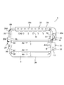
- Front sectional drawing which shows the inside of the heating cooker of 1st Embodiment of this invention.
- Front sectional drawing which shows the 2nd side part of the heating cooker of 1st Embodiment of this invention.
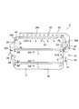
- Front sectional drawing which shows the inside of the heating cooker of 2nd Embodiment of this invention.
- Front sectional drawing which shows the inside of the heating cooker of 3rd Embodiment of this invention.
- FIG. 1 is a perspective view showing a heating cooker according to an embodiment.
- the heating cooker 1 has a heating chamber 2 having an opening 2d on the front surface for storing a cooked product, and the opening 2d is opened and closed by an open / close door 3 pivotally supported at the lower end.
- the heating chamber 2 is composed of a single-bottomed cylindrical box-shaped body 2e formed by drawing or the like, and a peripheral surface and a back surface are formed by the box-shaped body 2e.
- the open / close door 3 is filled with a heat insulating material, and a see-through window 4 such as heat resistant glass for visually recognizing the inside of the heating chamber 2 is provided at the center.
- an operation unit 5 for performing an input operation and the like is provided on the right side of the heating chamber 2.
- FIG. 2 shows a front sectional view of the inside of the heating cooker 1.
- a steam supply unit 10 is attached to the lower part of the right side wall of the heating chamber 2.
- the steam supply unit 10 embeds a steam generating heater 13 composed of a sheathed heater in a metal container having a water supply port 11 and a discharge port 12.
- the water supply port 11 is supplied with water for generating steam from a detachable water supply tank (not shown).
- the steam generating heater 13 evaporates the water supply port 11 to generate steam.
- the discharge port 12 opens to a circulation duct 20 to be described later, and discharges steam generated by the steam supply unit 10 to the upstream side of the circulation fan 21.
- a plurality of installation portions 6 in which the placement trays 7 on which the food is placed are installed are provided on both side walls of the heating chamber 2 in the vertical direction. Thereby, the mounting tray 7 can be cooked in a plurality of stages. Note that an opening through which airflow can pass is provided in the handle portion around the mounting tray 7.
- a suction port 2a is opened, and in the left side wall and the ceiling wall, outlets 2b and 2c are opened.
- the suction port 2a is arranged above the upper installation portion 6.
- the blower outlet 2b opens widely from the upper part of the upper installation part 4 to the lower part of the lower installation part 4. You may divide and provide the blower outlet 2b up and down.
- the blower outlet 2c is formed by many small holes.
- the inlet 2a and the outlet 2b are connected by a circulation duct 20 disposed outside the heating chamber 2.
- the circulation duct 20 has first and second side surfaces 20a and 20b and a top surface 20c.
- a suction port 2a is provided in the first side surface portion 20a, and an outlet 2b is provided in the second side surface portion 20b.
- the top surface portion 20c is provided so as to protrude inside the box-shaped body 2e, and the air outlet 2c is provided.
- the top surface portion 20c and the second side surface portion 20b are connected by a connecting portion 20d including a plurality of pipes that bend the circulation duct 20.
- a circulation fan 21 and a heater 22 are provided in the circulation duct 20.
- the circulation fan 21 is composed of a centrifugal fan or the like, and takes the steam in the heating chamber 2 into the circulation duct 20 from the suction port 2a.
- the steam flowing through the circulation duct 20 is blown into the heating chamber 2 from the blowout ports 2b and 2c. Thereby, the steam in the heating chamber 2 circulates through the circulation duct 20.
- the heater 22 is composed of a sheathed heater and heats steam flowing through the circulation duct 20 disposed on the top surface 20c. Thereby, steam can be maintained at a predetermined temperature and cooking with saturated steam or superheated steam can be performed. In addition, the cooked food is heated by radiant heat released from the heater 22 disposed on the top surface portion 20c into the heating chamber 2.
- the heater 22 may be formed by an IH heater.
- FIG. 3 is a front sectional view showing details of the second side surface portion 20b.
- the second side surface portion 20b is provided with a protrusion 24 that protrudes in the direction of the heating chamber 2 from the inner wall that is remote from the heating chamber 2.
- the arrangement and length of the protrusions 24 are adjusted to control the flow of steam from the outlet 2b. Therefore, good cooking can be performed with an appropriate amount of steam for heating the lower surface of the upper cooking item and the upper and lower surfaces of the lower cooking item.
- the cooking device 1 configured as described above, when cooking is placed on the placing tray 7 and cooking is started, water is supplied from the water supply tank (not shown) to the steam supply unit 10 through the water supply port 11.
- the water supplied to the steam supply unit 10 is evaporated by the steam generation heater 13 to generate steam, and the steam is discharged from the discharge port 12 into the circulation duct 20.
- the heater 22 When the heater 22 is energized, the upper surface of the upper cooking item is heated by the radiant heat of the heater 22.
- the circulation fan 21 When the circulation fan 21 is driven, the steam flowing into the circulation duct 20 from the discharge port 12 flows through the circulation duct 20. Further, the steam blown into the heating chamber 2 flows into the circulation duct 20 as indicated by an arrow A1 through the suction port 2a and flows through the circulation duct 20. The steam taken into the circulation duct 20 is guided from the first side surface portion 20a to the top surface portion 20c as indicated by an arrow A2. The steam flowing through the top surface portion 20c is heated with the heater 22 through heat exchange. At this time, cooking with saturated steam may be performed while maintaining the steam at a temperature in the vicinity of 100 ° C., or cooking with superheated steam may be performed while maintaining the steam at 100 ° C. or higher (for example, 300 ° C.).
- a part of the steam descending the second side surface portion 20b is blown out from the outlet 2b to the lower side of the upper loading tray 7 by the protrusion 24 as shown by an arrow A5.
- the steam descending beyond the protrusion 24 as shown by the arrow A6 is blown out from the outlet 2b to the upper and lower sides of the lower loading tray as shown by the arrows A7 and A8.
- the steam descends from the top surface portion 20c toward the side surface portion 20c, the steam is blown out obliquely downward from the air outlet 2b.
- the steam blown into the heating chamber 2 flows toward the right side wall as indicated by an arrow A9. Thereby, the lower surface of the upper cooking item and the upper and lower surfaces of the lower cooking item are heated.
- the steam in the heating chamber 2 is circulated by connecting the suction port 2a that opens to one of the opposing side walls of the heating chamber 2 and the air outlet 2b that opens to the other side wall by the circulation duct 20. Therefore, the steam is blown out in the lateral direction from the outlet 2b. Thereby, the collision of the heated steam to the open / close door 3 having the transparent window 4 is reduced. Therefore, since the opening / closing door 3 can be formed thin, the volume of the heating chamber 2 can be increased, and the volume ratio of the heating chamber 2 can be improved. Moreover, since it contacts with external air and the contact of the low-temperature see-through window 4 and steam decreases, a heat loss can be reduced and the heating efficiency of the heating cooker 1 can be improved.
- the heater 22 heating unit for heating the steam flowing through the circulation duct 20 is provided in the circulation duct 20, the steam can be easily maintained at a desired temperature.
- the circulation duct 20 may connect the first and second side surface portions 20a and 20b via the lower side and the rear side of the heating chamber 2.
- the circulation duct 20 connects the first and second side surface portions 20a and 20b via the top surface portion 20c and the heater 22 is disposed on the top surface portion 20c, the cooked food is easily heated by the radiant heat of the heater 22. It is possible to improve the heating efficiency.
- the depth of the heating chamber 2 can be secured widely and the depth of the heating cooker 1 can be narrowed.
- the cooking-by-heating machine 1 can be installed in a cooking stand with a narrow depth (for example, depth is 45 cm). Therefore, the convenience of the heating cooker 1 can be improved.
- the air outlet 2c including a plurality of small holes facing the heating chamber 2 is provided in the top surface portion 20c, the upper surface of the cooked food can be uniformly heated by the steam descending from the entire upper surface of the heating chamber 2.
- FIG. 4 shows a front sectional view of the inside of the heating cooker 1 of the second embodiment.
- the same reference numerals are given to the same parts as those in the first embodiment shown in FIGS.
- the present embodiment is different from the first embodiment in the configuration of the connecting portion 20d that connects the top surface portion 2c and the second side surface portion 2b. Other parts are the same as those of the first embodiment.
- the top surface portion 2c is provided so as to protrude inside the box-shaped body 2e, and a large number of holes (not shown) are provided on the end surface on the second side surface portion 2b side.
- a separating plate 2f made of a curved plate is disposed inside the box-shaped body 2e, and a connecting portion 20d is formed between the box-shaped body 2e and the separating plate 2f.
- the outer surface of the connecting portion 20d is formed by the box-shaped body 2e, and the inner surface is formed by the wall surface of the heating chamber 2.
- the connecting portion 20d is thermally insulated integrally with the heating chamber 2 by a heat insulating material (not shown) that covers the box-like body 2e, the top surface portion 2c, and the second side surface portion 20b.
- the same effect as that of the first embodiment can be obtained. Furthermore, since the inner surface of the connecting portion 20d is formed by the wall surface of the heating chamber 2, there is no need to insulate the inner surface side of the connecting portion 20d, and the outer surface side is integrally heat-insulated with the top surface portion 2c and the second side surface portion 20b. can do. Therefore, it is possible to insulate the connecting portion 20d more easily than the connecting portion 20d made of the pipe of the first embodiment. Moreover, the flow path area of the connection part 20d can be enlarged easily, and ventilation efficiency can be improved.
- the separator plate 2g may be formed of a flat plate, but a large volume in the heating chamber 2 can be secured by using a curved plate.
- FIG. 5 shows a front sectional view of the inside of the heating cooker 1 of the third embodiment.
- the same reference numerals are given to the same parts as those in the first embodiment shown in FIGS.
- the present embodiment is different from the first embodiment in the configuration of the connecting portion 20d that connects the top surface portion 2c and the second side surface portion 2b. Other parts are the same as those of the first embodiment.
- the outer surfaces of the top surface portion 2c, the connecting portion 20d, and the second side surface portion 20b are integrally formed of the same member.
- the inner surface of the connecting portion 20d is formed by the wall surface of the heating chamber 2 composed of the box-like body 2e.
- the connecting portion 20d is thermally insulated integrally with the heating chamber 2 by a heat insulating material (not shown) that covers the box-like body 2e, the top surface portion 2c, and the second side surface portion 20b.
- the same effect as that of the first embodiment can be obtained. Furthermore, since the inner surface of the connecting portion 20d is formed by the wall surface of the heating chamber 2, there is no need to insulate the inner surface side of the connecting portion 20d, and the outer surface side is integrally heat-insulated with the top surface portion 2c and the second side surface portion 20b. can do. Therefore, it is possible to insulate the connecting portion 20d more easily than the connecting portion 20d made of the pipe of the first embodiment. Moreover, the flow path area of the connection part 20d can be enlarged easily, and ventilation efficiency can be improved. In addition, since the amount of heat released from the connecting portion 20d can be reduced, an energy saving effect can be obtained.
- the discharge port 12 of the steam supply unit 10 may be opened to the heating chamber 2, and saturated steam or superheated steam may be discharged from the steam supply unit 10 to the heating chamber 2.
- a heating cooker to which steam is not supplied may be used. That is, the air in the heating chamber 2 may be circulated through the circulation duct 20, heated, and cooked with hot air.
- a separation plate that branches the airflow in the direction of the lower side and the second side surface portion 20b may be provided on the top surface portion 20c.
- a desired amount of steam can be blown out from the outlets 2b and 2c. Therefore, good cooking can be performed by appropriately adjusting the amount of steam for heating the upper surface of the upper cooking item from the blower outlet 2c and the amount of steam for heating the lower surface of the cooking item or lower cooking item from the blower outlet 2b.
- the heater 22 may be provided inside the second side surface portion 20b. Thereby, the temperature of the steam which blows off from the blower outlet 2b can be made high. Therefore, it is effective when the temperature of the steam at the air outlet 2b is higher than that at the air outlet 2c, or when a heat loss occurs in the circulation path at the initial stage of heating and the temperature of the steam is lowered.
- the protrusion 24 provided in the second side surface portion 20b may be movable so that the amount of steam flowing below the protrusion 24 can be adjusted. Thereby, the quantity of blowing steam can be adjusted above and below the heating chamber 2. Further, when the food is not arranged on the lower mounting tray 7, it is possible to reduce the heat loss by blowing out steam only above the upper mounting tray 7.
- the present invention can be used in a cooking device that performs cooking by circulating gas in a heating chamber.
Landscapes
- Engineering & Computer Science (AREA)
- Chemical & Material Sciences (AREA)
- Combustion & Propulsion (AREA)
- Mechanical Engineering (AREA)
- General Engineering & Computer Science (AREA)
- Electric Stoves And Ranges (AREA)
- Baking, Grill, Roasting (AREA)
Abstract
Description
2 加熱室
2a 吸込口
2b、2c 吹出口
2e 箱状体
2f 隔離板
3 開閉扉
4 透視窓
5 操作パネル
6 設置部
7 載置トレイ
10 蒸気供給部
11 給水口
12 吐出口
13 蒸気発生ヒータ
20 循環ダクト
20a 第1側面部
20b 第2側面部
20c 天面部
20d 連結部
21 循環ファン
22 加熱ヒータ
24 突起部
Claims (11)
- 前面に開口部を有して調理物を収納する加熱室と、透視窓を有して前記開口部を開閉する開閉扉と、前記加熱室の対向する側壁の一方に開口する吸込口と、前記加熱室の他方の側壁に開口する吹出口と、前記加熱室の両側壁の外側に配される第1、第2側面部を有して第1側面部に設けられる前記吸込口と第2側面部に設けられる前記吹出口とを連結する循環ダクトと、前記循環ダクト内に設けられるとともに前記加熱室内の気体を前記吸込口から吸い込んで前記吹出口から吹き出す循環ファンとを備えたことを特徴とする加熱調理器。
- 前記循環ダクトを流通する気体を加熱する加熱部を前記循環ダクト内に設けたことを特徴とする請求項1に記載の加熱調理器。
- 前記循環ダクトは前記加熱室の上方に設けた天面部を介して第1、第2側面部を連結し、前記加熱部を前記天面部に配したことを特徴とする請求項2に記載の加熱調理器。
- 前記加熱室に臨む複数の小孔を前記天面部に設けたことを特徴とする請求項3に記載の加熱調理器。
- 調理物を載置する載置トレイを設置する設置部を前記加熱室の内壁に突設し、前記設置部の上方に前記吸込口を配置したことを特徴とする請求項3に記載の加熱調理器。
- 前記設置部を上下に複数設けるとともに上方の前記設置部よりも下方に前記吹出口を配置し、第2側面部の前記加熱室から離れた内壁に前記加熱室の方向に突出する突起部を設けたことを特徴とする請求項5に記載の加熱調理器。
- 前記天面部と第2側面部とを連結して前記循環ダクトを屈曲させる連結部を有し、前記連結部の内面が前記加熱室の壁面により形成されることを特徴とする請求項3に記載の加熱調理器。
- 前記加熱室の周面及び背面を形成する単一部材から成る有底筒状の箱状体を有し、前記天面部が前記箱状体の内側に突出するとともに、前記箱状体の内側に配された隔離板によって前記連結部の内面を形成したことを特徴とする請求項7に記載の加熱調理器。
- 前記隔離板が曲面板から成ることを特徴とする請求項8に記載の加熱調理器。
- 前記天面部、前記連結部及び第2側面部の外面を同一部材により一体に形成したことを特徴とする請求項7に記載の加熱調理器。
- 前記加熱室に蒸気を供給する蒸気供給部を設けたことを特徴とする請求項1~請求項10のいずれかに記載の加熱調理器。
Priority Applications (2)
| Application Number | Priority Date | Filing Date | Title |
|---|---|---|---|
| US12/999,518 US9625162B2 (en) | 2008-07-30 | 2009-07-24 | Heating cooker |
| CN2009801295549A CN102105745B (zh) | 2008-07-30 | 2009-07-24 | 加热烹饪器 |
Applications Claiming Priority (4)
| Application Number | Priority Date | Filing Date | Title |
|---|---|---|---|
| JP2008195621 | 2008-07-30 | ||
| JP2008-195621 | 2008-07-30 | ||
| JP2009014893A JP4457166B2 (ja) | 2008-07-30 | 2009-01-27 | 加熱調理器 |
| JP2009-014893 | 2009-01-27 |
Publications (1)
| Publication Number | Publication Date |
|---|---|
| WO2010013650A1 true WO2010013650A1 (ja) | 2010-02-04 |
Family
ID=41610349
Family Applications (1)
| Application Number | Title | Priority Date | Filing Date |
|---|---|---|---|
| PCT/JP2009/063262 Ceased WO2010013650A1 (ja) | 2008-07-30 | 2009-07-24 | 加熱調理器 |
Country Status (4)
| Country | Link |
|---|---|
| US (1) | US9625162B2 (ja) |
| JP (1) | JP4457166B2 (ja) |
| CN (1) | CN102105745B (ja) |
| WO (1) | WO2010013650A1 (ja) |
Cited By (2)
| Publication number | Priority date | Publication date | Assignee | Title |
|---|---|---|---|---|
| CN112902233A (zh) * | 2021-01-25 | 2021-06-04 | 宁波方太厨具有限公司 | 一种烹饪设备及集成灶 |
| US20210204371A1 (en) * | 2019-12-25 | 2021-07-01 | Sharp Kabushiki Kaisha | Heating cooking apparatus |
Families Citing this family (9)
| Publication number | Priority date | Publication date | Assignee | Title |
|---|---|---|---|---|
| JP5732231B2 (ja) * | 2010-11-05 | 2015-06-10 | シャープ株式会社 | 加熱調理器 |
| JP5744496B2 (ja) * | 2010-12-09 | 2015-07-08 | シャープ株式会社 | 加熱調理器 |
| JP5827197B2 (ja) * | 2012-10-05 | 2015-12-02 | 三菱電機株式会社 | 加熱調理器 |
| KR102227410B1 (ko) * | 2014-09-02 | 2021-03-12 | 삼성전자주식회사 | 조리 기기 |
| US10415836B2 (en) * | 2015-02-06 | 2019-09-17 | Michael James McIntyre | Cooking apparatus and air delivery and circulation device therefore |
| JP5947951B2 (ja) * | 2015-04-28 | 2016-07-06 | シャープ株式会社 | 加熱調理器 |
| JP6002305B2 (ja) * | 2015-10-15 | 2016-10-05 | 三菱電機株式会社 | 加熱調理器 |
| TWD176912S (zh) * | 2015-10-23 | 2016-07-11 | 陳献楨 | 蒸盤 |
| US12016105B2 (en) * | 2019-11-25 | 2024-06-18 | Bsh Home Appliances Corporation | Home appliance cavity |
Citations (4)
| Publication number | Priority date | Publication date | Assignee | Title |
|---|---|---|---|---|
| JPH09126462A (ja) * | 1995-11-01 | 1997-05-16 | Tokyo Gas Co Ltd | コンベクションオーブン |
| JPH09126461A (ja) * | 1995-11-01 | 1997-05-16 | Tokyo Gas Co Ltd | 調理用加熱装置 |
| JP2005114350A (ja) * | 2004-12-01 | 2005-04-28 | Matsushita Electric Ind Co Ltd | 加熱装置 |
| JP2005265227A (ja) * | 2004-03-16 | 2005-09-29 | Mitsubishi Electric Corp | 加熱調理器 |
Family Cites Families (32)
| Publication number | Priority date | Publication date | Assignee | Title |
|---|---|---|---|---|
| US3384068A (en) * | 1966-12-09 | 1968-05-21 | American Gas Ass | Gas oven system |
| US3615972A (en) * | 1967-04-28 | 1971-10-26 | Dow Chemical Co | Expansible thermoplastic polymer particles containing volatile fluid foaming agent and method of foaming the same |
| US3658047A (en) * | 1970-11-05 | 1972-04-25 | Norris Food Service Inc | Food warming oven with removable tray racks |
| US4029463A (en) * | 1973-01-26 | 1977-06-14 | Tipe Revent Ab | Method for baking food products |
| US3945956A (en) * | 1975-06-23 | 1976-03-23 | The Dow Chemical Company | Polymerization of styrene acrylonitrile expandable microspheres |
| JPS6021770B2 (ja) * | 1980-02-14 | 1985-05-29 | 松本油脂製薬株式会社 | 熱膨張性マイクロカプセルの製造法 |
| JPS56149531A (en) * | 1980-04-22 | 1981-11-19 | Sharp Corp | Hot-air circulation type cooker |
| US5038748A (en) * | 1990-08-30 | 1991-08-13 | General Electric Company | Self-cleaning gas range having heat baffle assembly |
| JP3659979B2 (ja) * | 1992-04-15 | 2005-06-15 | 松本油脂製薬株式会社 | 熱膨張性マイクロカプセルとその製法 |
| US5693242A (en) * | 1993-10-06 | 1997-12-02 | Sanchez; Francisca Sanchez | Convection air oven |
| ES2076874B1 (es) * | 1993-11-26 | 1998-11-01 | Sanchez Sanchez Francisca | Horno perfeccionado. |
| CA2191730A1 (en) * | 1994-05-25 | 1995-11-30 | Dennis Wassman | Convectively-enhanced radiant heat oven |
| IT1268279B1 (it) * | 1994-07-29 | 1997-02-27 | Polin & C Spa Ing | Forno di cottura, in particolare per pane o prodotti di pasticceria |
| KR0126719Y1 (ko) * | 1995-10-07 | 1998-10-01 | 김광호 | 전자렌지 |
| SE515406C2 (sv) * | 1996-04-22 | 2001-07-30 | Sveba Dahlen Ab | Ugn och förfarande för alstring av värme till en ugn |
| WO1999043758A1 (en) * | 1998-02-24 | 1999-09-02 | Matsumoto Yushi-Seiyaku Co., Ltd. | Heat-expandable microcapsules, process for producing the same, and method of utilizing the same |
| WO1999046320A1 (en) * | 1998-03-13 | 1999-09-16 | Matsumoto Yushi-Seiyaku Co., Ltd. | Heat-expandable microcapsules and method of utilizing the same |
| US6291808B1 (en) * | 1999-09-13 | 2001-09-18 | Maytag Corporation | Heating system for a microwave and convection cooking appliance |
| TR200202805T2 (tr) * | 1999-10-15 | 2003-03-21 | Cargill Incorporated | Bitki tohumlarından yapılan fiberler ve kullanımları |
| US6509384B2 (en) * | 2000-04-28 | 2003-01-21 | Akzo Nobel N.V. | Chemical product and method |
| CA2447273A1 (en) * | 2001-05-25 | 2002-12-05 | Apache Products Company | Expandable microspheres for foam insulation and methods |
| JP3894825B2 (ja) * | 2001-12-28 | 2007-03-22 | シャープ株式会社 | 加熱調理器 |
| US6837234B2 (en) * | 2002-05-03 | 2005-01-04 | Premark Feg L.L.C. | Oven heat exchanger and floor construction |
| JP2004069175A (ja) * | 2002-08-06 | 2004-03-04 | Matsushita Electric Ind Co Ltd | 高周波加熱装置 |
| US6880544B2 (en) * | 2002-12-10 | 2005-04-19 | Lang Manufacturing Company | Rack oven |
| JP3701295B2 (ja) * | 2003-05-15 | 2005-09-28 | シャープ株式会社 | 加熱調理器 |
| US20080105249A1 (en) * | 2003-07-07 | 2008-05-08 | Turbochef Technologies, Inc. | Speed cooking oven with radiant mode |
| JP3710460B2 (ja) * | 2003-07-31 | 2005-10-26 | シャープ株式会社 | 蒸気調理器 |
| US7205507B2 (en) * | 2004-12-01 | 2007-04-17 | Lomaglio F Leo | Food cooking and heating apparatus |
| US20060135676A1 (en) * | 2004-12-17 | 2006-06-22 | Akzo Nobel N.V. | Composition |
| DE102005059505A1 (de) * | 2005-12-06 | 2007-06-14 | E.G.O. Elektro-Gerätebau GmbH | Haushaltsgerät und Verfahren zum Betrieb eines Haushaltsgeräts |
| JP4106382B2 (ja) * | 2006-05-25 | 2008-06-25 | シャープ株式会社 | 加熱調理器 |
-
2009
- 2009-01-27 JP JP2009014893A patent/JP4457166B2/ja not_active Expired - Fee Related
- 2009-07-24 CN CN2009801295549A patent/CN102105745B/zh not_active Expired - Fee Related
- 2009-07-24 WO PCT/JP2009/063262 patent/WO2010013650A1/ja not_active Ceased
- 2009-07-24 US US12/999,518 patent/US9625162B2/en not_active Expired - Fee Related
Patent Citations (4)
| Publication number | Priority date | Publication date | Assignee | Title |
|---|---|---|---|---|
| JPH09126462A (ja) * | 1995-11-01 | 1997-05-16 | Tokyo Gas Co Ltd | コンベクションオーブン |
| JPH09126461A (ja) * | 1995-11-01 | 1997-05-16 | Tokyo Gas Co Ltd | 調理用加熱装置 |
| JP2005265227A (ja) * | 2004-03-16 | 2005-09-29 | Mitsubishi Electric Corp | 加熱調理器 |
| JP2005114350A (ja) * | 2004-12-01 | 2005-04-28 | Matsushita Electric Ind Co Ltd | 加熱装置 |
Cited By (3)
| Publication number | Priority date | Publication date | Assignee | Title |
|---|---|---|---|---|
| US20210204371A1 (en) * | 2019-12-25 | 2021-07-01 | Sharp Kabushiki Kaisha | Heating cooking apparatus |
| US11864297B2 (en) * | 2019-12-25 | 2024-01-02 | Sharp Kabushiki Kaisha | Heating cooking apparatus |
| CN112902233A (zh) * | 2021-01-25 | 2021-06-04 | 宁波方太厨具有限公司 | 一种烹饪设备及集成灶 |
Also Published As
| Publication number | Publication date |
|---|---|
| JP4457166B2 (ja) | 2010-04-28 |
| JP2010054185A (ja) | 2010-03-11 |
| CN102105745B (zh) | 2013-03-27 |
| US9625162B2 (en) | 2017-04-18 |
| US20110126819A1 (en) | 2011-06-02 |
| CN102105745A (zh) | 2011-06-22 |
Similar Documents
| Publication | Publication Date | Title |
|---|---|---|
| JP4457166B2 (ja) | 加熱調理器 | |
| CN101153705B (zh) | 蒸汽发生器和具有该蒸汽发生器的加热烹饪设备 | |
| EP1795812B1 (en) | Cooking appliance | |
| CN102472497B (zh) | 加热烹调器 | |
| US8256409B2 (en) | Heating cooker | |
| CN104246374B (zh) | 加热烹调器 | |
| US20130019854A1 (en) | Oven door | |
| US20140144423A1 (en) | Gas oven range | |
| CN110840233B (zh) | 一种蒸微一体机 | |
| JP6382153B2 (ja) | 加熱調理器 | |
| JP2010007984A (ja) | 加熱調理器 | |
| JP2010266106A (ja) | 加熱調理器 | |
| WO2015125490A1 (ja) | マイクロ波加熱調理器 | |
| KR200353573Y1 (ko) | 전기오븐의 도어 냉각 시스템 | |
| KR100634789B1 (ko) | 가열조리장치 | |
| JP7381401B2 (ja) | 加熱調理器 | |
| JP6209733B2 (ja) | 加熱調理器 | |
| JP5284220B2 (ja) | 加熱調理器 | |
| JP6298652B2 (ja) | 加熱調理器 | |
| JP6156725B2 (ja) | 加熱調理器 | |
| KR102853490B1 (ko) | 오븐레인지 | |
| JP2006003030A (ja) | 加熱調理器 | |
| JP2012098005A (ja) | 加熱調理器 | |
| JP2011231962A (ja) | 加熱調理器 | |
| JP4689535B2 (ja) | 加熱調理器 |
Legal Events
| Date | Code | Title | Description |
|---|---|---|---|
| WWE | Wipo information: entry into national phase |
Ref document number: 200980129554.9 Country of ref document: CN |
|
| 121 | Ep: the epo has been informed by wipo that ep was designated in this application |
Ref document number: 09802893 Country of ref document: EP Kind code of ref document: A1 |
|
| WWE | Wipo information: entry into national phase |
Ref document number: 12999518 Country of ref document: US |
|
| NENP | Non-entry into the national phase |
Ref country code: DE |
|
| 122 | Ep: pct application non-entry in european phase |
Ref document number: 09802893 Country of ref document: EP Kind code of ref document: A1 |