WO2010013409A1 - スラストころ軸受およびその保持器 - Google Patents
スラストころ軸受およびその保持器 Download PDFInfo
- Publication number
- WO2010013409A1 WO2010013409A1 PCT/JP2009/003431 JP2009003431W WO2010013409A1 WO 2010013409 A1 WO2010013409 A1 WO 2010013409A1 JP 2009003431 W JP2009003431 W JP 2009003431W WO 2010013409 A1 WO2010013409 A1 WO 2010013409A1
- Authority
- WO
- WIPO (PCT)
- Prior art keywords
- cage
- diameter side
- roller bearing
- plate
- thrust roller
- Prior art date
- Legal status (The legal status is an assumption and is not a legal conclusion. Google has not performed a legal analysis and makes no representation as to the accuracy of the status listed.)
- Ceased
Links
Images






Classifications
-
- F—MECHANICAL ENGINEERING; LIGHTING; HEATING; WEAPONS; BLASTING
- F16—ENGINEERING ELEMENTS AND UNITS; GENERAL MEASURES FOR PRODUCING AND MAINTAINING EFFECTIVE FUNCTIONING OF MACHINES OR INSTALLATIONS; THERMAL INSULATION IN GENERAL
- F16C—SHAFTS; FLEXIBLE SHAFTS; ELEMENTS OR CRANKSHAFT MECHANISMS; ROTARY BODIES OTHER THAN GEARING ELEMENTS; BEARINGS
- F16C19/00—Bearings with rolling contact, for exclusively rotary movement
- F16C19/22—Bearings with rolling contact, for exclusively rotary movement with bearing rollers essentially of the same size in one or more circular rows, e.g. needle bearings
- F16C19/30—Bearings with rolling contact, for exclusively rotary movement with bearing rollers essentially of the same size in one or more circular rows, e.g. needle bearings for axial load mainly
-
- F—MECHANICAL ENGINEERING; LIGHTING; HEATING; WEAPONS; BLASTING
- F16—ENGINEERING ELEMENTS AND UNITS; GENERAL MEASURES FOR PRODUCING AND MAINTAINING EFFECTIVE FUNCTIONING OF MACHINES OR INSTALLATIONS; THERMAL INSULATION IN GENERAL
- F16C—SHAFTS; FLEXIBLE SHAFTS; ELEMENTS OR CRANKSHAFT MECHANISMS; ROTARY BODIES OTHER THAN GEARING ELEMENTS; BEARINGS
- F16C33/00—Parts of bearings; Special methods for making bearings or parts thereof
- F16C33/30—Parts of ball or roller bearings
- F16C33/46—Cages for rollers or needles
- F16C33/54—Cages for rollers or needles made from wire, strips, or sheet metal
- F16C33/542—Cages for rollers or needles made from wire, strips, or sheet metal made from sheet metal
- F16C33/547—Cages for rollers or needles made from wire, strips, or sheet metal made from sheet metal from two parts, e.g. two discs or rings joined together
-
- F—MECHANICAL ENGINEERING; LIGHTING; HEATING; WEAPONS; BLASTING
- F16—ENGINEERING ELEMENTS AND UNITS; GENERAL MEASURES FOR PRODUCING AND MAINTAINING EFFECTIVE FUNCTIONING OF MACHINES OR INSTALLATIONS; THERMAL INSULATION IN GENERAL
- F16C—SHAFTS; FLEXIBLE SHAFTS; ELEMENTS OR CRANKSHAFT MECHANISMS; ROTARY BODIES OTHER THAN GEARING ELEMENTS; BEARINGS
- F16C2240/00—Specified values or numerical ranges of parameters; Relations between them
- F16C2240/40—Linear dimensions, e.g. length, radius, thickness, gap
-
- F—MECHANICAL ENGINEERING; LIGHTING; HEATING; WEAPONS; BLASTING
- F16—ENGINEERING ELEMENTS AND UNITS; GENERAL MEASURES FOR PRODUCING AND MAINTAINING EFFECTIVE FUNCTIONING OF MACHINES OR INSTALLATIONS; THERMAL INSULATION IN GENERAL
- F16C—SHAFTS; FLEXIBLE SHAFTS; ELEMENTS OR CRANKSHAFT MECHANISMS; ROTARY BODIES OTHER THAN GEARING ELEMENTS; BEARINGS
- F16C2240/00—Specified values or numerical ranges of parameters; Relations between them
- F16C2240/40—Linear dimensions, e.g. length, radius, thickness, gap
- F16C2240/60—Thickness, e.g. thickness of coatings
-
- F—MECHANICAL ENGINEERING; LIGHTING; HEATING; WEAPONS; BLASTING
- F16—ENGINEERING ELEMENTS AND UNITS; GENERAL MEASURES FOR PRODUCING AND MAINTAINING EFFECTIVE FUNCTIONING OF MACHINES OR INSTALLATIONS; THERMAL INSULATION IN GENERAL
- F16C—SHAFTS; FLEXIBLE SHAFTS; ELEMENTS OR CRANKSHAFT MECHANISMS; ROTARY BODIES OTHER THAN GEARING ELEMENTS; BEARINGS
- F16C2360/00—Engines or pumps
- F16C2360/44—Centrifugal pumps
-
- F—MECHANICAL ENGINEERING; LIGHTING; HEATING; WEAPONS; BLASTING
- F16—ENGINEERING ELEMENTS AND UNITS; GENERAL MEASURES FOR PRODUCING AND MAINTAINING EFFECTIVE FUNCTIONING OF MACHINES OR INSTALLATIONS; THERMAL INSULATION IN GENERAL
- F16C—SHAFTS; FLEXIBLE SHAFTS; ELEMENTS OR CRANKSHAFT MECHANISMS; ROTARY BODIES OTHER THAN GEARING ELEMENTS; BEARINGS
- F16C2361/00—Apparatus or articles in engineering in general
- F16C2361/61—Toothed gear systems, e.g. support of pinion shafts
Definitions
- the present invention relates to a thrust roller bearing used in an automobile transmission, a torque converter, a car air-conditioning compressor, and the like, and a cage for the same.
- each pocket 33 includes two pocket holes 34 and 35 that are provided in the radial direction between the two retainer constituting plates 21 and 22 and overlap each other in the axial direction.
- the inner diameter side end and the outer diameter side end of the lower cage component plate 22 are bent portions 22a and 22b bent upward in the axial direction, and the inner diameter side end and the outer diameter side end of the upper cage component plate 21.
- the surface of the roller 24 is exposed more as the axial thickness of the outer diameter side portion and the inner diameter side portion of the cage 30 is made thinner as in the conventional example 2 shown in FIG.
- the lubricity is improved, but for example, the joining area of the cylindrical portions 21a, 22a extending in the axial direction of the upper and lower cage constituting plates 21, 22 at the inner diameter side portion of the cage 30 is reduced.
- the two cage constituting plates 21 and 22 are displaced in the radial direction.
- the inner diameter side end and the outer diameter side end of the upper cage component plate 21 are connected to the lower cage component plate 22 on the inner diameter side end and outer diameter side of the cage 30.
- the rollers 24 are sandwiched between the edges of the upper and lower pocket holes 34 and 35. Get locked up. If the roller 24 is locked and does not rotate, adverse effects such as an extreme decrease in life and an increase in torque occur.
- the object of the present invention is to improve lubricity while ensuring sufficient strength of the cage, and to improve assembly without causing roller locking even if the cage component plate is displaced during caulking of the cage. It is an object to provide a thrust roller bearing and a cage for the same.
- the thrust roller bearing according to the present invention is provided with pockets at a plurality of circumferential positions in a cage comprising at least a first cage component plate and a second cage component plate that are axially overlapped with each other.
- the first retainer constituting plate is located on the inner diameter side and the outer diameter side with respect to each other, two peripheral side flat portions that are flat portions facing each other in the axial direction, and A central flat portion that is in the middle of the radial direction with respect to both peripheral side flat portions and that is axially biased, and the second retainer component plate is biased by the central flat portion of the first retainer component plate A continuous flat portion that overlaps with the flat portions on both peripheral sides of the first retainer constituting plate on the surface opposite to the direction, and one of the first and second retainer constituting plates
- This cage is folded from the inner periphery Folded from the outer peripheral edge of one of the first and second cage component plates and the inner diameter side folded portion that sandwiches the flat portion of the other cage component plate with the flat portion of the component plate An
- the thickness of at least one of the peripheral edges of each of the first and second cage constituting plates was made thinner than the thickness of the intermediate portion in the radial direction of either one of the first and second cage constituting plates.
- one or both of the first and second retainer constituting plates constituting the retainer are folded back from the inner peripheral edge and the outer peripheral edge, and either one of the retainer Since it has an inner diameter side folded portion and an outer diameter side folded portion that sandwich the flat portion of the other cage component plate with the flat portion of the component plate, the strength of the cage can be secured sufficiently, at the time of high-speed rotation, etc. There is no possibility that the first and second cage component plates are displaced in the radial direction.
- the cage of the conventional thrust roller bearing is a box-shaped cage having a substantially rectangular cross section, whereas the cage in this thrust roller bearing has a substantially triangular cross section.
- a large amount of oil can be exposed from the cage, and sufficient oil permeability can be secured.
- at least one of the thicknesses of the folded portions, the peripheral edge flat portions, and the inner and outer peripheral edges of the continuous flat portion is set to the radial intermediate portion of the first and second cage component plates. Since the thickness of the roller is thinner than either one of the plates, the surface of the roller is exposed more from the cage while maintaining the strength of the intermediate portion in the radial direction of each cage component plate that becomes the roller holding portion. And sufficient oil permeability can be secured.
- the portion of the other cage component plate sandwiched between the folded portion and the flat portion of one cage component plate is also a flat portion, the entire axial thickness of the inner diameter portion and outer diameter portion of the cage The thickness can be reduced, and the surface of the roller can be exposed more from the cage. Thereby, lubricity can be improved while sufficiently securing the strength of the cage.
- the inner diameter side folded portion and the outer diameter side folded portion may be provided over the entire circumference of the cage constituting plate.
- the inner diameter side folded portion and the outer diameter side folded portion may be folded in the same axial direction.
- the inner diameter side folded portion and the outer diameter side folded portion may be formed by folding a flat plate portion of the cage component plate.
- the plate thicknesses of the inner diameter side folding portion and the outer diameter side folding portion are set to the radial intermediate portions of the first and second cage component plates. The operation of making it thinner than the plate thickness can be easily performed.
- At least one of the thicknesses of the folded portions, the peripheral flat portions, and the peripheral flat portions is set to one of the first and second retainer constituting plates. It may be 50 to 95% of the thickness of the intermediate portion in the radial direction.
- the thickness of the intermediate portion in the radial direction of the first and second cage component plates may be different from each other.
- a flat raceway plate portion and an inner ring having a cylindrical portion extending from the inner peripheral edge of the raceway plate portion, a flat raceway plate portion facing the raceway plate portion of the inner race, and an outer peripheral edge of the raceway plate portion
- An outer ring having a cylindrical portion extending from the inner ring side to the inner ring side, the retainer, and the rollers, and each roller held by the retainer is interposed between the inner ring and the raceway plate portion of the outer ring, and is relatively
- a thrust roller bearing retainer used in the thrust roller bearing according to the invention According to this thrust roller bearing cage, a thrust roller bearing cage capable of improving lubricity while ensuring sufficient strength can be obtained.
- each of the pockets includes two pocket holes that are provided in the radial direction between the first and second cage component plates and overlap each other in the axial direction.
- the directional dimension was longer than the other radial dimension.
- each pocket includes two pocket holes that are provided in the radial direction between the first and second cage component plates and overlap each other in the axial direction. It is longer than the other radial dimension. For this reason, when caulking the inner and outer diameter side ends of the cage, even if the two cage component plates are displaced in the radial direction, the pocket hole having a short radial dimension is located inside the pocket hole having a long radial dimension. As long as it is accommodated, the roller will be accommodated inside a pocket hole having a long radial dimension, so that the roller will not be locked and the assemblability can be improved.
- the sum of the radial clearance dimensions between the folded portion and the peripheral flat portion at the inner diameter side end and the outer diameter side end of the cage is the radial dimension between the pocket holes. It may be shorter than the difference.
- both the cage component plates are in the radial direction until the peripheral flat portion of one cage component plate hits the folded portion of the other cage component plate.
- the pocket hole having a short radial dimension is accommodated inside the pocket hole having a long radial dimension. Therefore, it is possible to reliably prevent the rollers from locking.
- the tip position of the folded portion is a position that is radially out of one of the pocket holes that is long in the radial direction. In this configuration, even if both cage component plates are displaced in the radial direction until the end surface of the roller reaches near the opening edge of the pocket hole with a long radial dimension, the tip of the folded portion is prevented from hitting the end surface of the roller and locking. it can.
- one pocket hole having a shorter radial dimension among the two pocket holes may be disposed closer to the roller center in the axial direction than the other pocket hole.
- the cage pocket holds the end face of the roller at a portion close to the center thereof, and the occurrence of drilling wear on the end face of the roller can be reduced.
- a retainer for a thrust roller bearing used in the thrust roller bearing is provided. According to this cage for thrust roller bearings, when the inner and outer diameter side ends of the cage are caulked, even if the two cage constituting plates are displaced in the radial direction, the roller is placed inside the pocket hole having a long radial dimension. As a result, the roller is not locked and the assemblability can be improved.
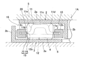
- FIG. 1 shows a cross-sectional view of the thrust roller bearing of this embodiment.
- This thrust roller bearing 1 is a cage roller type thrust roller bearing which is composed of an annular cage 10 and a roller 4 held by the cage 10, that is, only a roller with a cage.
- the cage 10 is composed of at least an annular first cage component plate 11 and a second cage component plate 12 that are axially overlapped with each other, and rollers 4 are provided in pockets 13 provided at a plurality of locations in the circumferential direction. Retained.
- the first cage component plate 11 has a cross-sectional shape including two peripheral side flat portions 11a and 11b, a central flat portion 11c, an inner diameter side continuous portion 11d, and an outer diameter side continuous portion 11e.
- the two peripheral side flat portions 11a and 11b are plate-like portions that are located on the inner diameter side and the outer diameter side, respectively, and face the axial direction.
- the central flat part 11c is a flat plate-like part located in the middle of the radial direction with respect to the peripheral side flat part 11a positioned on the inner diameter side and the peripheral side flat part 11b positioned on the outer diameter side, and being offset in the axial direction. is there.
- the inner diameter side continuous portion 11d is an inclined portion that extends from the outer peripheral edge of the peripheral flat portion 11a located on the inner diameter side to the inner peripheral edge of the central flat portion 11c.
- the outer diameter side continuous part 11e is an inclined part continuing from the outer peripheral edge of the central flat part 11c to the inner peripheral edge of the peripheral flat part 11b located on the outer shape side.
- the second cage component plate 12 has a cross-sectional shape including a continuous flat portion 12a, an inner diameter side folded portion 12b, and an outer diameter side folded portion 12c.
- the continuous flat portion 12a is a portion that overlaps the two peripheral flat portions 11a and 11b of the first retainer constituting plate 11 on the surface opposite to the biasing direction of the central flat portion 11c of the first retainer constituting plate 11. It is.
- the inner diameter side folded portion 12b is a portion formed by folding a flat plate portion extending from the inner peripheral edge of the continuous flat portion 12a.
- the outer diameter side folded portion 12c is a portion formed by folding a flat plate portion extending from the outer peripheral edge of the continuous flat portion 12a.
- the inner diameter side folded portion 12b has a flat plate-like portion extending from the inner peripheral edge of the continuous flat portion 12a to the peripheral flat portion 11a of the first cage constituting plate 11 and is swung around the continuous flat portion 12a. It is a part used as the crimping part which pinches
- the outer diameter side folded portion 12c is crimped to the peripheral flat portion 11b of the first cage constituting plate 11 by crimping a flat plate-like portion extending from the outer peripheral edge of the continuous flat portion 12a. It is a part used as the crimping part which pinches
- the inner diameter side folded portion 12 b and the outer diameter side folded portion 12 c are provided over the entire circumference of the second cage component plate 12.
- the pocket 13 of the cage 10 that holds the rollers 4 includes a pocket hole 14 formed by stamping in the middle of the first cage component plate 11 in the radial direction and the radial direction of the second cage component plate 12.
- the pocket hole 14 is formed by punching in the middle of the pocket hole 14 and the pocket hole 15 is overlapped in the axial direction.
- the pocket holes 14 and 15 of the first and second cage component plates 11 and 12 are formed in the first cage component plate 11 and the second cage component plate 12 before the folded portion is formed in FIG. After being formed into a shape, the material is punched and formed by pressing using a punching die (not shown). Thereafter, the first cage component plate 11 and the second cage component plate 12 are crimped to form a folded portion.
- the punching of the pocket holes 14 and 15 may be performed collectively after the cage component plates 11 and 12 are swaged (folded portion formation), and before each portion of the cage component plates 11 and 12 is molded. You can go.
- the cage 10 is disposed between the two members 7 and 8 so that the pair of mating members 7 and 8 that are opposed to each other in the axial direction and rotate relative to each other become the rolling surfaces that the rollers 4 come into contact with. Is done.
- the thickness of at least one of the portion 11b (plate thickness t11b) and the inner peripheral edge (plate thickness t12aa) and outer peripheral edge (plate thickness (t12ab) of the continuous flat portion 12a is the first and second holdings. It is made thinner than either one of the plate thickness t11c ⁇ or t12a at the radial intermediate portion of the component constituting plates 11 and 12.
- the plate thickness t12b or t12c of the folded portions 12b and 12c, both peripheral flat portions The plate thicknesses t11a and t11b of 11a and 11b are thinner than the plate thicknesses t11c and t12a in the radial direction of the first and second cage constituting plates 11 and 12 (specifically, the plate thicknesses t11c and t12a). 50 to 95%).
- the plate thicknesses t12b and t12c of the folded portions 12b and 12c are subjected to caulking treatment while being thinly stretched when bent, thereby obtaining a plate thickness t11c of the intermediate portion in the radial direction of the first and second cage constituting plates 11 and 12; Thinner than t12a.
- the plate thickness of the plate-like portion before the turn-up portions 12b and 12c may be reduced in advance.
- the thickness t11c and t12a of the first and second cage constituting plates 11 and 12 in the radial direction are substantially the same, but these plate thicknesses may be different from each other. .
- the thrust roller bearing 1 having this configuration, in the cage 10 that includes the first and second cage component plates 11 and 12 that are axially overlapped with each other and holds the roller 4, as shown in FIG.
- the cage is a box-shaped cage having a substantially rectangular cross section, whereas in the cage 10 in the thrust roller bearing 1, the first holding is performed.
- the container component plate 11 has two peripheral side flat portions 11a and 11b located on the inner diameter side and the outer diameter side, and a center that is in the middle of the radial direction with respect to both the peripheral side flat portions 11a and 11b and is offset in the axial direction.
- the second retainer component plate 12 has a flat portion 11c, and both sides of the first retainer component plate 11 on the surface opposite to the biasing direction of the central flat portion 11c of the first retainer component plate 11 Since it has the continuous flat part 12a which overlaps over the edge side flat parts 11a and 11b and the cross section has a substantially triangular shape, the surface of the roller 4 can be exposed from the cage 10 in a large amount and has sufficient oil permeability. Can be secured.
- the folded portions 12b and 12c (plate thickness t12b), the both peripheral side flat portions 11a and 11b (plate thickness t12c), and the inner and outer peripheral edges (plate thickness t12aa and t12ab) of the continuous flat portion 12a. Since the plate thickness at one location is made thinner than either one of the plate thicknesses t11c and t12a ⁇ in the radial direction of the first and second cage constituting plates 11 and 12, the holding portion of the roller 4 The surface of the roller 4 can be more exposed from the retainer 10 while maintaining the strength of the intermediate portion in the radial direction of each retainer constituting plate 11, 12, and further sufficient oil permeability can be ensured. .
- the inner and outer peripheral portions of the second retainer constituting plate 11 sandwiched between the folded portions 12b and 12c of the second retainer constituting plate 12 and the continuous flat portion 12a are respectively formed as the peripheral flat portions 11a and 11b. Also from this, the axial thickness of the entire inner diameter portion and outer diameter portion of the cage 10 can be reduced, and the surface of the roller 4 can be more exposed from the cage 10. Thereby, lubricity can be improved while sufficiently securing the strength of the cage 10.
- both the bent portions 12b and 12c are formed on the inner diameter edge and the outer diameter edge of the continuous flat portion 12a of the second cage component plate 12, that is, both the bent portions 12b and 12c are axially connected to each other.
- the outer peripheral edge of the peripheral flat portion 11b located on the outer diameter side of the first retainer component plate 11 is set downward as the outer diameter side folded portion 11f.
- the outer diameter edge of the continuous flat portion 12a of the second cage component plate 12 may be sandwiched.
- the inner peripheral edge of the peripheral side flat part 11a located in the internal diameter side in the 1st retainer structure board 11 is turned down as an inner diameter side folding
- the inner and outer peripheral edges of the first retainer constituting plate 11 are folded downward so that the inner diameter side folded portion 11g, and the outer diameter side folded portion 11h may be formed.
- FIG. 4 shows a fourth embodiment of the present invention.
- an annular inner ring 2 that is one of the bearing rings and an annular ring that is the other bearing ring that is arranged concentrically with the inner ring 2.
- the outer ring 3 is provided.
- the inner ring 2 has an inverted L-shaped cross section having a flat raceway plate portion 2a and a cylindrical portion 2b extending from the inner periphery of the raceway plate portion 2a.
- the outer ring 3 has an L-shaped cross section including a flat plate-shaped track plate portion 3a facing the track plate portion 2a of the inner ring 2 and a cylindrical portion 3b extending from the outer peripheral edge of the track plate portion 3a to the inner ring 2 side.
- the roller 4 held by the cage 10 is interposed between the raceway plate portions 2a and 3a of the inner ring 2 and the outer ring 3, and the three-piece unitary structure in which the roller with cage 20 and the inner and outer rings 2 and 3 are not separated.
- a shaped thrust roller bearing 1A is formed.
- the inner ring 2 and the outer ring 3 are supported in contact with opposed surfaces of a pair of bearing ring support members 5 and 6 that rotate relative to each other.
- an oil supply opening is provided between the outer peripheral edge of the raceway plate portion 2a of the inner ring 2 and the tip of the cylindrical portion 3b of the outer ring 3, that is, on the side where the inner ring 2 is disposed in the axial direction and on the outer peripheral edge side. 16 is provided.
- the roller with retainer 20 is arranged with the central flat portion 11c of the first retainer constituting plate 11 facing the oil supply side, that is, the axial direction where the oil supply opening 16 is located.
- Other configurations are the same as those of the first embodiment of FIG.
- the first cage component plate 11 is oriented in the direction toward the oil supply side in the axial direction.
- FIGS. A fifth embodiment of the present invention will be described with reference to FIGS.
- the same or corresponding parts as those in FIG. 1 showing the first embodiment are denoted by the same reference numerals, and detailed description thereof is omitted.
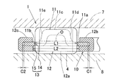
- the radial dimension L2 of the pocket hole 15 of the second cage component plate 12 is the same as that of the first cage component plate 11.
- the pocket hole 14 is longer than the radial dimension L1.
- the tip positions of the inner diameter side folded portion 12b and the outer diameter side folded portion 12c of the second cage component plate 12 are positions that are radially deviated from the pocket hole 15 having a long radial dimension.
- the radial gap dimension C1 between the inner diameter side folded portion 12b and the peripheral side flat portion 11a and the radial gap dimension C2 between the outer diameter side folded portion 12c and the peripheral side flat portion 11b. Is made shorter than the difference (L2 ⁇ L1) in the radial dimension between the pocket holes 14 and 15. That is, C ⁇ L2-L1 (1)
- the relational expression is established.
- the pocket hole 14 of the first cage component plate 11 having a short radial dimension is closer to the center O of the roller 4 in the axial direction than the pocket hole 15 of the second cage component plate 12 having a large radial dimension. It is arranged at a close position.
- each pocket 13 of the cage 10 is provided in the middle of the first and second cage component plates 11 and 12 in the radial direction, and two pocket holes 14 that overlap each other in the axial direction.
- one of the pocket holes 14, 15 has a radial dimension L 2 longer than the other radial dimension L 1.
- the cage 10 When the inner and outer diameter side ends are crimped, even if the two retainer constituting plates 11 and 12 are displaced in the radial direction, the rollers 4 are accommodated inside the pocket holes 15 having the radial dimension L2, and the rollers 4 are Locking can be prevented.
- the inner diameter side folded portion is formed on the inner peripheral edge of the first cage constituting plate 11, or when the outer diameter side folded portion is formed on the outer circumferential edge of the first cage constituting plate 11, or both folded portions. This is the same even when formed on the inner and outer edges of the first cage constituting plate 11.
- the folded portions 12b and 12c of the second cage component plate 12 at the inner diameter side end and the outer diameter side end of the cage 10 and the peripheral side flat portion 11a of the first cage component plate 11 are provided.
- the retainer constituting plates 11 and 12 are moved until one peripheral flat portion 11a hits the inner diameter side folded portion 12b. Even if the rollers 4 are displaced in the radial direction, the rollers 4 are accommodated inside the pocket holes 15 having the radial dimension L2, and the rollers 4 can be reliably prevented from locking.
- the radial dimension L2 of one pocket hole 15 may be longer than the radial dimension L1 of the other pocket hole 14, for example, FIG. 7, when the two cage constituting plates 11 and 12 are displaced in the radial direction until one peripheral flat portion 11 a hits the inner diameter side folded portion 12 b, the opening edge of the pocket hole 14 and the pocket hole 15 A situation may occur in which the roller 4 is caught between the opening edge and locked.
- the pocket hole 14 of the first cage component plate 11 having a short radial dimension is smaller in the axial direction than the pocket hole 15 of the second cage component plate 12 having a long radial dimension.
- the pocket 13 of the cage 10 holds the end face of the roller 4 at a portion close to the center O, thereby reducing the occurrence of drilling wear on the end face of the roller 4. it can.
- the tip positions of the inner diameter side folded portion 12b and the outer diameter side folded portion 12c of the second cage component plate 12 are set to positions that are radially deviated from the pocket holes 15 having a long radial dimension. Therefore, even if both the cage component plates 11 and 12 are displaced in the radial direction until the end face of the roller 4 reaches the vicinity of the opening edge of the pocket hole 15 having a long radial dimension, the inner diameter side folded portion 12b and the outer diameter side folded portion 12c. It can prevent that the front-end
- FIG. 8 shows a sixth embodiment of the present invention.
- the distal end positions of the inner diameter side folded portion 12b and the outer diameter side folded portion 12c of the second cage component plate 12 have radial dimensions. It is located inside the long pocket hole 15 in the radial direction. However, even in this case, the distal end positions of the inner diameter side folded portion 12b and the outer diameter side folded portion 12c are set to positions deviated from the pocket hole 14 having a short radial dimension in the radial direction.
- Other configurations are the same as those of the fifth embodiment of FIG.
- the limit value of the radial displacement amount of the two cage constituting plates 11 and 12 that the roller 4 does not lock is the radius between the tips of the inner diameter side folded portion 12b and the outer diameter side folded portion 12c.
- FIG. 9 shows a seventh embodiment of the present invention.
- the thrust roller bearing 1B is a cage roller type thrust roller bearing including an annular box-shaped cage 10A and rollers 4 held by the cage 10A.
- the cage 10A is composed of an annular first cage component plate 11A and second cage component plate 12A that are axially overlapped with each other, and the rollers 4 are held in pockets 13 provided at a plurality of locations in the circumferential direction. Is done.
- Each pocket 13 includes two pocket holes 14 and 15 that are provided in the radial direction between the two retainer constituting plates 11A and 12A and overlap each other in the axial direction.
- the radial dimension L2 of the pocket hole 15 of the cage component plate 12A is longer than the radial dimension L1 of the pocket hole 14 of the first cage component plate 11A.
- the inner diameter side end and the outer diameter side end of the second cage component plate 12A are bent portions 12Aa and 12Ab which are bent upward in the axial direction, and the inner diameter side end and the outer diameter side of the first cage component plate 11A.
- the ends are bent portions 11Aa and 11Ab which are bent downward in the axial direction.
- the inner diameter side end of the first cage component plate 11A is crimped to the inner diameter side of the bent portion 12Aa of the second cage component plate 12A, and the bent portion 11Aa By doing so, both the retainer constituting plates 11A and 12A are coupled.
- the outer diameter side end of the first cage component plate 11A is crimped to the outer diameter side of the bent portion 12Ab of the second cage component plate 12A.
- the bent portion 11Ab the two cage constituting plates 11A and 12A are coupled.
- the radial dimension L2 of the pocket hole 15 of the second cage component plate 12A is longer than the radial dimension L1 of the pocket hole 14 of the first cage component plate 11A. is doing. For this reason, when caulking the inner and outer diameter side ends of the cage 10A, even if the two cage component plates 11A and 12A are displaced in the radial direction, the rollers 4 are accommodated inside the pocket hole 15 having the radial dimension L2. As a result, the rollers 4 can be prevented from locking, and the assemblability can be improved.
- the thrust roller bearing according to aspect 1 is provided with pockets at a plurality of circumferential positions in a cage composed of a first cage component plate and a second cage component plate that are axially overlapped with each other.
- a thrust roller bearing in which the first and second cage constituting plates add either one to the other at the inner diameter side end and the outer diameter side end of the cage.
- the pockets are joined by tightened caulking portions, and each of the pockets includes two pocket holes provided in the radial direction between the first and second cage component plates and overlapping each other in the axial direction. The radial dimension of either one of the holes was made longer than the other radial dimension.
- each pocket includes two pocket holes that are provided in the radial direction between the first and second cage component plates and overlap each other in the axial direction. It is longer than the other radial dimension. For this reason, when caulking the inner and outer diameter side ends of the cage, even if the two cage component plates are displaced in the radial direction, the pocket hole having a short radial dimension is located inside the pocket hole having a long radial dimension. As long as it is accommodated, the roller will be accommodated inside a pocket hole having a long radial dimension, so that the roller will not be locked and the assemblability can be improved.
- the crimping portion at the inner diameter side end and the outer diameter side end of the cage is a folded portion formed by folding back one of the peripheral edges of the first and second cage component plates.
- the sum of the radial clearance dimensions between the folded portion and the peripheral flat portion at the inner diameter side end and the outer diameter side end is the radial direction between the pocket holes. It may be shorter than the difference in dimensions.
- both the cage component plates are in the radial direction until the peripheral flat portion of one cage component plate hits the folded portion of the other cage component plate.
- the pocket hole having a short radial dimension is accommodated inside the pocket hole having a long radial dimension. Therefore, it is possible to reliably prevent the rollers from locking.
- the tip position of the folded portion is a position that is radially out of one of the pocket holes that is long in the radial direction. In this configuration, even if both cage component plates are displaced in the radial direction until the end surface of the roller reaches near the opening edge of the pocket hole with a long radial dimension, the tip of the folded portion is prevented from hitting the end surface of the roller and locking. it can.
- the inner diameter side end and outer diameter side end crimping portions of the cage may be provided over the entire circumference of the cage.
- the caulking portion at the inner diameter side end and the outer diameter side end of the cage is a folded portion formed by folding back one of the peripheral edges of the first and second cage constituting plates, and the other It is also possible to sandwich the flat portion of the peripheral edge of the rim, and the folding direction of the folded portion may be the same direction.
- one pocket hole having a short radial dimension among the two pocket holes may be disposed closer to the roller center in the axial direction than the other pocket hole.
- the cage pocket holds the end face of the roller at a portion close to the center thereof, and the occurrence of drilling wear on the end face of the roller can be reduced.
- second cage component plate 12a continuous flat portion 12b ... inner diameter side folded portion (caulking portion) 12c ... Outer diameter side folded portion (caulking portion) 12Aa, 12Ab ... bent part (clamping part) 13 ... Pockets 14, 15 ... Pocket holes 16 ... Oil opening 20 ... Rollers with cage
Landscapes
- Engineering & Computer Science (AREA)
- General Engineering & Computer Science (AREA)
- Mechanical Engineering (AREA)
- Rolling Contact Bearings (AREA)
Abstract
保持器強度を十分確保し潤滑性の向上が可能なスラストころ軸受を提供する。2枚の保持器構成板(11,12)からなる保持器(10)を有し、その円周方向に並ぶポケット(13)にころ(4)が保持される。第1の保持器構成板(11)は、内外径側に位置する周縁側平坦部(11a,11b)と、各周縁側平坦部(11a,11b)から軸方向に偏った中央平坦部(11c)を有する。第2の保持器構成板(12)は、各周縁側平坦部(11a,11b)と重なる連続平坦部(12a)と、その内外周縁から折り返された各折返し部(12b,12c)を有する。各折返し部(12b,12c)と連続平坦部(12a)の間に、保持器構成板(11)の各周縁側平坦部(11a,11b)が挟み込まれる。各折返し部(12b,12c)、各周縁側平坦部(11a,11b)、および連続平坦部(12a)の両周縁の少なくともいずれか1箇所以上の板厚を、各保持器構成板(11,12)の半径方向の中間部板厚よりも薄くする。
Description
本出願は、2008年7月28日出願の特願2008-193473、および2008年8月11日出願の特願2008-207112の優先権を主張するものであり、その全体を参照により本願の一部をなすものとして引用する。
この発明は、自動車用トランスミッション、トルクコンバーター、カーエアコン用コンプレッサー等に使用されるスラストころ軸受、およびその保持器に関する。
従来のスラストころ軸受として、例えば図10に示す従来例1のように2枚の保持器構成板21,22を軸方向に重ねて箱型保持器30としたものが知られている。この保持器30には円周方向複数箇所にポケット33が設けられ、これら各ポケット33にころ24が保持される。各ポケット33は、前記2枚の保持器構成板21,22の半径方向の中間に設けられ互いに軸方向に重なる2つのポケット孔34,35からなり、これら両ポケット孔34,35の半径方向寸法は同一である。下側の保持器構成板22の内径側端および外径側端は軸方向の上側に折り曲げた折曲げ部22a,22bとされ、上側の保持器構成板21の内径側端および外径側端は軸方向の下側に折り曲げた折り曲げ部21a,21bとされている。この保持器30の内径側端では、上側の保持器構成板21の内径側端を、下側の保持器構成板22の折曲げ部22aの内径側に加締めて前記折曲げ部21aとすることで、両保持器構成板21,22が結合されている。また、保持器30の外径側端では、上側の保持器構成板21の外径側端を、下側の保持器構成板22の折曲げ部22bの外径側に加締めて前記折曲げ部21bとすることで、両保持器構成板21,22が結合されている。
また、このように箱型保持器30としたスラストころ軸受において、潤滑性を向上させたものとして、図11に示す従来例2による構成のものが提案されている(例えば特許文献1)。このスラストころ軸受では、保持器30における外径側部および内径側部の軸方向厚さt1,t2が、ころ保持部となる半径方向の中間部での軸方向厚さt0よりも薄く形成されている。この構成によると、図10のスラストころ軸受に比べて、ころ24の表面が保持器30からより多く露出するので、潤滑性の向上が見込める。
また、このように箱型保持器30としたスラストころ軸受において、潤滑性を向上させたものとして、図11に示す従来例2による構成のものが提案されている(例えば特許文献1)。このスラストころ軸受では、保持器30における外径側部および内径側部の軸方向厚さt1,t2が、ころ保持部となる半径方向の中間部での軸方向厚さt0よりも薄く形成されている。この構成によると、図10のスラストころ軸受に比べて、ころ24の表面が保持器30からより多く露出するので、潤滑性の向上が見込める。
箱型保持器としたスラストころ軸受では、保持器30における外径側部や内径側部の軸方向厚さを図10に示す従来例2のように薄くするほど、ころ24の表面が多く露出して潤滑性が向上するが、それでは例えば保持器30の内径側部において上下の保持器構成板21、22の軸方向に延びる円筒部21a,22aの接合面積が減り、高速回転時などにおいて、2枚の保持器構成板21,22が径方向にずれるおそれがある。
また、従来例1による構成の場合、保持器30の内径側端および外径側で、上側の保持器構成板21の内径側端および外径側端を、下側の保持器構成板22の各折曲げ部22a,22bに加締める際に、上下の保持器構成板21,22の間で半径方向へのずれが生じると、ころ24が上下のポケット孔34,35の口縁に挟み付けられてロックしてしまう。ころ24がロックして回転しなくなると、極端な寿命低下やトルクの増大などの悪影響が発生する。
この発明の目的は、保持器の強度を十分確保しつつ潤滑性の向上が可能な、また保持器の加締め時に保持器構成板がずれてもころのロックが生じず、組立性を向上させることのできるスラストころ軸受、およびその保持器を提供することである。
この発明のスラストころ軸受は、互いに軸方向に重なる少なくとも第1の保持器構成板および第2の保持器構成板からなる保持器における円周方向複数箇所にポケットが設けられ、これら各ポケットにころが保持されたスラストころ軸受であって、前記第1の保持器構成板は、互いに内径側および外径側に位置しそれぞれ軸方向に向く平板状の部分である2つの周縁側平坦部と、これら両周縁側平坦部に対して半径方向の中間にあって軸方向に偏った中央平坦部を有し、前記第2の保持器構成板は、第1の保持器構成板の中央平坦部の偏り方向と反対側の面で第1の保持器構成板の両周縁側平坦部にわたって重なる連続平坦部を有し、前記第1および第2の保持器構成板のいずれか一方の保持器構成板の内周縁から折り返されて、この保持器構成板の前記平坦部とで他方の保持器構成板の平坦部を挟み込む内径側折返し部と、前記第1および第2の保持器構成板のいずれか一方の保持器構成板の外周縁から折り返されて、この保持器構成板の前記平坦部とで他方の保持器構成板の平坦部を挟み込む外径側折返し部とを設け、前記両折返し部、前記両周縁側平坦部、および連続平坦部の周縁のうち、少なくともいずれか1箇所の板厚を、前記第1および第2の保持器構成板のいずれか一方の半径方向の中間部の板厚よりも薄くした。
この構成によると、保持器を構成する第1および第2の保持器構成板のいずれか一方または両方の保持器構成板が、その内周縁および外周縁から折り返されて、いずれか一方の保持器構成板の平坦部とでいずれか他方の保持器構成板の平坦部を挟み込む内径側折返し部と外径側折返し部を有するので、保持器の強度を十分確保できて、高速回転時などにおいて、第1および第2の保持器構成板が径方向にずれるおそれはない。
また、前記従来のスラストころ軸受の保持器が略長方形の断面の箱型保持器であるのに対して、このスラストころ軸受における保持器では、断面が略三角形状となっていることから、ころの表面を保持器から多く露出させることができて十分な通油性を確保することができる。
とくに、前記両折返し部、前記両周縁側平坦部、および連続平坦部の内外周縁のうち、少なくともいずれか1箇所の板厚を、第1および第2の保持器構成板の半径方向の中間部の板厚のいずれか一方よりも薄くされているので、ころの保持部となる各保持器構成板の半径方向中間部の強度を保った状態でころの表面を保持器からより多く露出させることができ、さらに十分な通油性を確保することができる。一方の保持器構成板の折返し部と平坦部とで挟み込まれる他方の保持器構成板の部分が平坦部とされていることからも、保持器の内径部および外径部の全体の軸方向厚さを薄くでき、ころの表面を保持器からより多く露出させることができる。これにより、保持器の強度を十分確保しつつ潤滑性の向上が可能となる。
この構成によると、保持器を構成する第1および第2の保持器構成板のいずれか一方または両方の保持器構成板が、その内周縁および外周縁から折り返されて、いずれか一方の保持器構成板の平坦部とでいずれか他方の保持器構成板の平坦部を挟み込む内径側折返し部と外径側折返し部を有するので、保持器の強度を十分確保できて、高速回転時などにおいて、第1および第2の保持器構成板が径方向にずれるおそれはない。
また、前記従来のスラストころ軸受の保持器が略長方形の断面の箱型保持器であるのに対して、このスラストころ軸受における保持器では、断面が略三角形状となっていることから、ころの表面を保持器から多く露出させることができて十分な通油性を確保することができる。
とくに、前記両折返し部、前記両周縁側平坦部、および連続平坦部の内外周縁のうち、少なくともいずれか1箇所の板厚を、第1および第2の保持器構成板の半径方向の中間部の板厚のいずれか一方よりも薄くされているので、ころの保持部となる各保持器構成板の半径方向中間部の強度を保った状態でころの表面を保持器からより多く露出させることができ、さらに十分な通油性を確保することができる。一方の保持器構成板の折返し部と平坦部とで挟み込まれる他方の保持器構成板の部分が平坦部とされていることからも、保持器の内径部および外径部の全体の軸方向厚さを薄くでき、ころの表面を保持器からより多く露出させることができる。これにより、保持器の強度を十分確保しつつ潤滑性の向上が可能となる。
この発明において、前記内径側折返し部および外径側折返し部は、前記保持器構成板の全周にわたって有するものとしても良い。
この発明において、前記内径側折返し部および外径側折返し部は、互いに軸方向の同一方向に折り返されたものであっても良い。
この発明において、前記内径側折返し部および外径側折返し部は、前記保持器構成板の平板状部を折り返して形成されるものであっても良い。この構成の場合、折り返し前に平板状部を薄くしておくことにより、内径側折返し部および外径側折返し部の板厚を、第1および第2の保持器構成板の径方向中間部の板厚よりも薄くする作業を容易に行うことができる。
この発明において、前記両折返し部、前記両周縁側平坦部、および連続平坦部の周縁のうち、少なくともいずれか1箇所の板厚を、前記第1および第2の保持器構成板のいずれか一方の半径方向の中間部の板厚の50~95%としても良い。
この発明において、前記第1および第2の保持器構成板の半径方向の中間部の板厚を互いに異ならせても良い。
この発明において、平板状の軌道板部およびこの軌道板部の内周縁から延びる円筒部を有する内輪と、この内輪の軌道板部に対面する平板状の軌道板部およびこの軌道板部の外周縁から内輪側へ延びる円筒部を有する外輪と,前記保持器と、前記ころとを備え、前記内輪および外輪の軌道板部の間に、前記保持器に保持された各ころが介在し、互いに相対回転する一対の軌道輪支持部材に前記内輪および外輪がそれぞれ支持されるスラストころ軸受であって、このスラストころ軸受の軸方向の給油側となる向きに、前記第1の保持器構成板の中央平坦部を向けて前記保持器を配置しても良い。
この構成の場合、保持器からころ表面の多く露出する側が給油側に向くことになるので、給油効率が良くなり、潤滑性がさらに向上する。
この構成の場合、保持器からころ表面の多く露出する側が給油側に向くことになるので、給油効率が良くなり、潤滑性がさらに向上する。
前記発明にかかるスラストころ軸受に用いられるスラストころ軸受用保持器。
このスラストころ軸受用保持器によると、強度を十分確保しつつ潤滑性の向上が可能なスラストころ軸受用保持器とすることができる。
このスラストころ軸受用保持器によると、強度を十分確保しつつ潤滑性の向上が可能なスラストころ軸受用保持器とすることができる。
この発明において、前記各ポケットが、前記第1および第2の保持器構成板の半径方向の中間に設けられ互いに軸方向に重なる2つのポケット孔からなり、これら両ポケット孔のいずれか一方の半径方向寸法をいずれか他方の半径方向寸法よりも長くした。
この構成によると、各ポケットが、第1および第2の保持器構成板の半径方向の中間に設けられ互いに軸方向に重なる2つのポケット孔からなるが、両ポケット孔の一方の半径方向寸法を他方の半径方向寸法よりも長くしている。このため、保持器の内外径側端を加締める際に、2枚の保持器構成板が半径方向にずれても、半径方向寸法の短いポケット孔が、半径方向寸法の長いポケット孔の内側に収まっている限り、ころは半径方向寸法の長いポケット孔の内側に収まることになり、ころにロックが生じず、組立性を向上させることができる。
この構成によると、各ポケットが、第1および第2の保持器構成板の半径方向の中間に設けられ互いに軸方向に重なる2つのポケット孔からなるが、両ポケット孔の一方の半径方向寸法を他方の半径方向寸法よりも長くしている。このため、保持器の内外径側端を加締める際に、2枚の保持器構成板が半径方向にずれても、半径方向寸法の短いポケット孔が、半径方向寸法の長いポケット孔の内側に収まっている限り、ころは半径方向寸法の長いポケット孔の内側に収まることになり、ころにロックが生じず、組立性を向上させることができる。
前記スラストころ軸受において、前記保持器の内径側端および外径側端における前記折返し部と前記周縁平坦部との間の径方向隙間寸法の総和を、前記両ポケット孔の間の半径方向寸法の差分よりも短くしても良い。
この構成の場合、保持器の内外径側端を加締める際に、一方の保持器構成板の周縁平坦部が他方の保持器構成板の折返し部に突き当たるまで、両保持器構成板が半径方向にずれたとしても、半径方向寸法の短いポケット孔が、半径方向寸法の長いポケット孔の内側に収まっている。そのため、ころがロックするのを確実に防止できる。
この構成の場合、保持器の内外径側端を加締める際に、一方の保持器構成板の周縁平坦部が他方の保持器構成板の折返し部に突き当たるまで、両保持器構成板が半径方向にずれたとしても、半径方向寸法の短いポケット孔が、半径方向寸法の長いポケット孔の内側に収まっている。そのため、ころがロックするのを確実に防止できる。
この構成の場合に、前記折返し部の先端位置を、前記両ポケット孔のうち半径方向の長い一方のポケット孔から径方向に外れた位置とするのが望ましい。この構成の場合、ころの端面が半径方向寸法の長いポケット孔の開口縁近くに達するまで両保持器構成板が半径方向にずれても、折返し部の先端がころの端面に当たってロックするのを防止できる。
前記スラストころ軸受において、前記両ポケット孔のうち半径方向寸法の短い一方のポケット孔を、他方のポケット孔よりも軸方向におけるころ中心に近い位置に配置しても良い。この構成の場合、保持器のポケットはころの端面をその中心に近い部分で保持することになり、ころの端面にドリリング摩耗が起きるのを低減できる。
前記スラストころ軸受に用いられるスラストころ軸受用保持器。
このスラストころ軸受用保持器によると、保持器の内外径側端を加締める際に、2枚の保持器構成板が半径方向にずれても、ころは半径方向寸法の長いポケット孔の内側に収まることになり、ころにロックが生じず、組立性を向上させることができる。
このスラストころ軸受用保持器によると、保持器の内外径側端を加締める際に、2枚の保持器構成板が半径方向にずれても、ころは半径方向寸法の長いポケット孔の内側に収まることになり、ころにロックが生じず、組立性を向上させることができる。
この発明は、添付の図面を参考にした以下の好適な実施形態の説明から、より明瞭に理解されるであろう。しかしながら、実施形態および図面は単なる図示および説明のためのものであり、この発明の範囲を定めるために利用されるべきでない。この発明の範囲は添付の請求の範囲によって定まる。添付図面において、複数の図面における同一の部品番号は、同一部分を示す。
この発明の第1実施形態にかかるスラストころ軸受の部分断面図である。
この発明の第2実施形態にかかるスラストころ軸受の部分断面図である。
この発明の第3実施形態にかかるスラストころ軸受の部分断面図である。
この発明の第4実施形態にかかるスラストころ軸受の部分断面図である。
この発明の第5実施形態にかかるスラストころ軸受の部分断面図である。
同スラストころ軸受における保持器加締め時の保持器構成板のずれの影響の説明図である。
同スラストころ軸受におけるポケット孔の寸法等の条件を異ならせた場合の保持器加締め時の保持器構成板のずれの影響の説明図である。
この発明の第6実施形態にかかるスラストころ軸受の部分断面図である。
この発明の第7実施形態にかかるスラストころ軸受の部分断面図である。
従来例1の断面図である。
従来例2の断面図である。
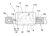
この発明の第1実施形態を図1と共に説明する。図1は、この実施形態のスラストころ軸受の断面図を示す。このスラストころ軸受1は、環状の保持器10と、この保持器10に保持されたころ4とからなる、つまり保持器付きころだけからなるケージ&ローラー形式のスラストころ軸受である。保持器10は、互いに軸方向に重なる少なくとも環状の第1の保持器構成板11と第2の保持器構成板12とでなり、円周方向複数箇所に設けられた各ポケット13にころ4が保持される。
第1の保持器構成板11は、2つの周縁側平坦部11a,11bと、中央平坦部11cと、内径側連続部11dと、外径側連続部11eとでなる断面形状とされている。2つの周縁側平坦部11a,11bは、互いに内径側および外径側に位置し、それぞれ軸方向を向く平板状の部分である。中央平坦部11cは、内径側に位置する周縁側平坦部11aおよび外径側に位置する周縁側平坦部11bに対して半径方向の中間にあって、軸方向に偏って位置する平板状の部分である。内径側連続部11dは、内径側に位置する周縁側平坦部11aの外周縁から中央平坦部11cの内周縁に続く傾斜部分である。外径側連続部11eは、中央平坦部11cの外周縁から外形側に位置する周縁側平坦部11bの内周縁に続く傾斜部分である。
第2の保持器構成板12は、連続平坦部12aと、内径側折返し部12bと、外径側折り返し部12cとでなる断面形状とされている。連続平坦部12aは、第1の保持器構成板11の中央平坦部11cの偏り方向と反対側の面で、第1の保持器構成板11の2つの周縁側平坦部11a,11bにわたって重なる部分である。内径側折返し部12bは、連続平坦部12aの内周縁から延びる平板状部を折り返して形成される部分である。外径側折返し部12cは、連続平坦部12aの外周縁から延びる平板状部を折り返して形成される部分である。これら両折返し部12b,12cは、例えば加締治具を用いた加締処理により折り返される。すなわち、内径側折返し部12bは、連続平坦部12aの内周縁から延びる平板状部を第1の保持器構成板11の周縁側平坦部11aに加締めて連続平坦部12aとの間に、周縁側平坦部11aを挟み込む加締め部となる部分である。また、外径側折返し部12cは、連続平坦部12aの外周縁から延びる平板状部を第1の保持器構成板11の周縁側平坦部11bに加締めて連続平坦部12aとの間に、周縁側平坦部11bを挟み込む加締め部となる部分である。内径側折返し部12bおよび外径側折返し部12cは、第2保持器構成板12の全周にわたって有するものとされる。
ころ4を保持する保持器10のポケット13は、第1の保持器構成板11の半径方向の中間にプレス加工により打ち抜き形成されたポケット孔14と、第2の保持器構成板12の半径方向の中間にプレス加工により打ち抜き形成され前記ポケット孔14と軸方向に重なるポケット孔15とでなる。これら第1および第2の保持器構成板11,12のポケット孔14,15は、第1の保持器構成板11および第2の保持器構成板12が図1において折り返し部が形成される前の形状に成形された後、打ち抜き用のプレス型(図示せず)を用いたプレス加工により打ち抜き形成される。その後、第1の保持器構成板11および第2の保持器構成板12が加締められ、折り返し部が形成される。ここで、各ポケット孔14,15の打ち抜き加工は、保持器構成板11,12の加締め(折り返し部形成)後に纏めて行っても良く、また保持器構成板11,12の各部成形前に行っても良い。
このスラストころ軸受では、軸方向に対向配置され互いに相対回転する一対の相手部材7,8が、ころ4の接触する転走面となるように、両部材7,8間に保持器10が配置される。
前記内周側折返し部12b(板厚t12b )、外周側折返し部12c(板厚t12c )、前記内径側に位置する周縁側平坦部11a(板厚t11a )、外径側に位置する周縁側平坦部11b(板厚t11b )、および連続平坦部12aの内周縁(板厚t12aa)と外周縁(板厚(t12ab)のうち、少なくともいずれか1箇所の板厚は、第1および第2の保持器構成板11,12の半径方向の中間部の板厚t11c ,t12a のいずれか一方よりも薄くされている。ここでは、両折返し部12b,12cの板厚t12b ,t12c 、両周縁側平坦部11a,11bの板厚t11a ,t11b が、第1および第2の保持器構成板11,12の半径方向の中間部の板厚t11c ,t12a よりも薄く(具体的には、板厚t11c ,t12a の50~95%)されている。
両折返し部12b,12cの板厚t12b ,t12c は、折り曲げ時に薄く延ばしながら加締処理することによって、第1および第2の保持器構成板11,12の半径方向の中間部の板厚t11c ,t12a よりも薄くされる。このほか、両折返し部12b,12cとなる折り返し前の平板状部の板厚を予め薄くしておくようにしても良い。
また、ここでは、第1および第2の保持器構成板11,12の半径方向の中間部の板厚t11c ,t12a は略同じとされているが、これらの板厚を互いに異ならせても良い。
この構成のスラストころ軸受1によると、互いに軸方向に重なる第1および第2の保持器構成板11,12からなりころ4を保持する保持器10において、例えば図1のように、第2の保持器構成板12の連続平坦部12aと、その内周縁および外周縁から折り返されされた内径側折返し部12bおよび外径側折返し部12cとで、第1の保持器構成板11の内径側および外径側に位置する両周縁側平坦部を挟み込むようにしているので、保持器10の強度を十分確保できて、高速回転時などにおいて、第1および第2の保持器構成板11,12が径方向にずれるおそれはない。内径側折返し部が第1の保持器構成板11の内周縁に形成される場合、あるいは外径側折返し部が第1の保持器構成板11の外周縁に形成される場合、あるいは両折返し部が第1の保持器構成板11の内外縁に形成される場合でも同様である。
また、図10や図11に例示した従来のスラストころ軸受では保持器が略長方形の断面の箱型保持器であるのに対して、このスラストころ軸受1における保持器10では、第1の保持器構成板11が、内径側および外径側に位置する2つの周縁側平坦部11a,11bと、これら両周縁側平坦部11a,11bに対して半径方向の中間にあって軸方向に偏った中央平坦部11cを有し、第2の保持器構成板12が、第1の保持器構成板11の中央平坦部11cの偏り方向と反対側の面で第1の保持器構成板11の両周縁側平坦部11a,11bにわたって重なる連続平坦部12aを有しており、断面が略三角形状となっていることから、ころ4の表面を保持器10から多く露出させることができて十分な通油性を確保することができる。
とくに、前記両折返し部12b,12c(板厚t12b )、前記両周縁側平坦部11a,11b(板厚t12c )、および連続平坦部12aの内外周縁(板厚t12aa,t12ab)のうち、少なくともいずれか1箇所の板厚が、第1および第2の保持器構成板11,12の半径方向の中間部の板厚t11c ,t12a のいずれか一方よりも薄くされているので、ころ4の保持部となる各保持器構成板11,12の半径方向中間部の強度を保った状態でころ4の表面を保持器10からより多く露出させることができ、さらに十分な通油性を確保することができる。第2の保持器構成板12の各折返し部12b,12cと連続平坦部12aとで挟み込まれる第2の保持器構成板11の内外の周縁部がそれぞれ周縁側平坦部11a,11bとされていることからも、保持器10の内径部および外径部の全体の軸方向厚さを薄くでき、ころ4の表面を保持器10からより多く露出させることができる。これにより、保持器10の強度を十分確保しつつ潤滑性の向上が可能となる。
なお、この実施形態では、第2の保持器構成板12の連続平坦部12aの内径縁と外径縁に折曲げ部12b,12cを形成した場合、つまり両折曲げ部12b,12cが互いに軸方向の同一方向に折り返された場合を例示した。しかし、例えば図2に示す第2実施形態のように、外径側折返し部11fとして、第1の保持器構成板11における外径側に位置する周縁側平坦部11bの外周縁を下側に折り返して、第2の保持器構成板12の連続平坦部12aの外径縁を挟み込むようにしても良い。また、図示は省略するが、内径側折返し部として、第1の保持器構成板11における内径側に位置する周縁側平坦部11aの内周縁を下側に折り返して、第2の保持器構成板12の連続平坦部12aの内径縁を挟み込むようにしても良い。また、さらに、他の例として、図3に示す第3実施形態のように、第1の保持器構成板11の内外周縁を下側に折り返して内径側折返し部11g,および外径側折返し部11hを形成しても良い。
図4は、この発明の第4実施形態を示す。この実施形態のスラストころ軸受1Aでは、図1の保持器付きころ20に加えて、一方の軌道輪である環状の内輪2と、この内輪2と同心に配置される他方の軌道輪である環状の外輪3とを備える。内輪2は、平板状の軌道板部2aと、この軌道板部2aの内周縁から延びる円筒部2bとを有する断面逆L字状とされている。外輪3は、内輪2の軌道板部2aに対面する平板状の軌道板部3aと、この軌道板部3aの外周縁から内輪2側へ延びる円筒部3bとを有する断面L字状とされている。これら内輪2および外輪3の軌道板部2a,3aの間に、保持器10に保持されたころ4が介在して、保持器付きころ20と内外輪2,3とが非分離となった三位一体形のスラストころ軸受1Aが構成される。
前記内輪2および外輪3は、互いに相対回転する一対の軌道輪支持部材5,6の対向面にそれぞれ接して支持される。
前記内輪2および外輪3は、互いに相対回転する一対の軌道輪支持部材5,6の対向面にそれぞれ接して支持される。
このスラストころ軸受1Aの場合、内輪2の軌道板部2aの外周縁と、外輪3の円筒部3bの先端との間、つまり軸方向における内輪2の配置側でかつ外周縁側に給油用の開口16が設けられている。また、保持器付きころ20は、その第1の保持器構成板11の中央平坦部11cを給油側、つまり前記給油用の開口16が位置する軸方向に向けて配置されている。その他の構成は図1の第1実施形態の場合と同様である。
このように、保持器付きころ20と内外輪2,3とが非分離となった三位一体形のスラストころ軸受1Aにおいて、軸方向の給油側となる向きに、第1の保持器構成板11の中央平坦部11cを向けて保持器10を配置することにより、保持器10からころ4の表面の多く露出する側が給油側に向くことになるので、給油効率が良くなり、潤滑性がさらに向上する。
この発明の第5実施形態を図5ないし図7と共に説明する。これらの図において、前記第1実施形態を示す図1と同一または相当する部分には同一の符号を付してその詳しい説明は省略する。
図5に示すように、この第5実施形態では、ポケット孔14,15のうち、第2の保持器構成板12のポケット孔15の半径方向寸法L2は、第1の保持器構成板11のポケット孔14の半径方向寸法L1よりも長くされている。また、第2の保持器構成板12の内径側折返し部12bおよび外径側折返し部12cの先端位置は、半径方向寸法の長いポケット孔15から径方向に外れた位置とされている。
また、この実施形態では、内径側折返し部12bと周縁側平坦部11aとの間の径方向隙間寸法C1と、外径側折返し部12cと周縁側平坦部11bとの間の径方向隙間寸法C2の総和C(=C1+C2)を、前記両ポケット孔14,15の間の半径方向寸法の差分(L2-L1)よりも短くしている。すなわち、
C<L2-L1……(1)
の関係式が成り立つようにしている。
C<L2-L1……(1)
の関係式が成り立つようにしている。
また、半径方向寸法の短い第1の保持器構成板11のポケット孔14は、半径方向寸法の長い第2の保持器構成板12のポケット孔15よりも、軸方向におけるころ4の中心Oに近い位置に配置される。
この構成のスラストころ軸受1によると、保持器10の各ポケット13が、第1および第2の保持器構成板11,12の半径方向の中間に設けられ互いに軸方向に重なる2つのポケット孔14,15からなるが、両ポケット孔14,15の一方の半径方向寸法L2を他方の半径方向寸法L1よりも長くしている。このため、保持器10の内外径側端を加締める際に、第1および第2の保持器構成板11,12が半径方向にずれても、ころ4がロックするのを防止でき、組立性が向上する。
すなわち、第2の保持器構成板12のポケット孔15の半径方向寸法L2を、第1の保持器構成板11のポケット孔14の半径方向寸法L1よりも長くしているので、保持器10の内外径側端を加締める際に、2枚の保持器構成板11,12が半径方向にずれても、ころ4は半径方向寸法L2のポケット孔15の内側に収まることになり、ころ4がロックするのを防止できる。内径側折返し部が第1の保持器構成板11の内周縁に形成される場合、あるいは外径側折返し部が第1の保持器構成板11の外周縁に形成される場合、あるいは両折返し部が第1の保持器構成板11の内外縁に形成される場合でも同様である。
すなわち、第2の保持器構成板12のポケット孔15の半径方向寸法L2を、第1の保持器構成板11のポケット孔14の半径方向寸法L1よりも長くしているので、保持器10の内外径側端を加締める際に、2枚の保持器構成板11,12が半径方向にずれても、ころ4は半径方向寸法L2のポケット孔15の内側に収まることになり、ころ4がロックするのを防止できる。内径側折返し部が第1の保持器構成板11の内周縁に形成される場合、あるいは外径側折返し部が第1の保持器構成板11の外周縁に形成される場合、あるいは両折返し部が第1の保持器構成板11の内外縁に形成される場合でも同様である。
とくに、この実施形態では、保持器10の内径側端および外径側端における第2の保持器構成板12の折返し部12b,12cと、第1の保持器構成板11の周縁側平坦部11a,11bとの間の径方向隙間寸法C1,C2の総和C(=C1+C2)を、前記両ポケット孔14,15の間の半径方向寸法の差分(L2-L1)よりも短くしている(C<L2-L1)。このため、保持器10の内外径側端を加締める際に、例えば図6のように、一方の周縁側平坦部11aが内径側折返し部12bに突き当たるまで、両保持器構成板11,12が半径方向にずれたとしても、ころ4は半径方向寸法L2のポケット孔15の内側に収まることになり、ころ4がロックするのを確実に防止できる。
ちなみに、上記したC<L2-L1の寸法関係にない場合には、一方のポケット孔15の半径方向寸法L2を他方のポケット孔14の半径方向寸法L1よりも長くしておいても、例えば図7のように、一方の周縁側平坦部11aが内径側折返し部12bに突き当たるまで、両保持器構成板11,12が半径方向にずれてしまうと、ポケット孔14の開口縁とポケット孔15の開口縁とでころ4が挟まれてロックする事態が生じ得る。
また、この実施形態では、半径方向寸法の短い第1の保持器構成板11のポケット孔14が、半径方向寸法の長い第2の保持器構成板12のポケット孔15よりも、軸方向におけるころ4の中心Oに近い位置に配置されているので、保持器10のポケット13はころ4の端面を中心Oに近い部分で保持することになり、ころ4の端面にドリリング摩耗が起きるのを低減できる。
また、この実施形態では、第2の保持器構成板12の内径側折返し部12bおよび外径側折返し部12cの先端位置を、半径方向寸法の長いポケット孔15から径方向に外れた位置としているので、ころ4の端面が半径方向寸法の長いポケット孔15の開口縁近くに達するまで両保持器構成板11,12が半径方向にずれても、内径側折返し部12bおよび外径側折返し部12cの先端がころ4の端面に当たってロックするのを防止できる。
図8は、この発明の第6実施形態を示す。この実施形態のスラストころ軸受1Aは、図5に示す第5実施形態において、第2の保持器構成板12の内径側折返し部12bおよび外径側折返し部12cの先端位置が、半径方向寸法の長いポケット孔15の径方向内側に位置されている。ただし、この場合でも、前記内径側折返し部12bおよび外径側折返し部12cの先端位置は、半径方向寸法の短いポケット孔14から径方向に外れた位置とされている。その他の構成は図5の第5実施形態の場合と同様である。
この実施形態の場合、ころ4がロックしてしまわない両保持器構成板11,12の半径方向のずれ量の限界値は、内径側折返し部12bと外径側折返し部12cの先端間の半径方向寸法により決まるが、両保持器構成板11,12がある程度まで半径方向にずれてもころ4がロックするのを防止する効果は得られる。つまり、半径方向寸法の短いポケット孔14が、内径側折返し部12bと外径側折返し部12cの先端間からなる半径方向寸ポケット孔の内側に収まっている限り、ころがロックするのを確実に防止できる。
図9は、この発明の第7実施形態を示す。このスラストころ軸受1Bは、環状の箱型保持器10Aと、この保持器10Aに保持されたころ4とからなるケージ&ローラー形式のスラストころ軸受である。保持器10Aは、互いに軸方向に重なる環状の第1の保持器構成板11Aと第2の保持器構成板12Aとでなり、円周方向複数箇所に設けられた各ポケット13にころ4が保持される。各ポケット13は、前記両保持器構成板11A,12Aの半径方向の中間に設けられ互いに軸方向に重なる2つのポケット孔14,15からなり、これら両ポケット孔14,15のうち、第2の保持器構成板12Aのポケット孔15の半径方向寸法L2は、第1の保持器構成板11Aのポケット孔14の半径方向寸法L1よりも長くされている。
第2の保持器構成板12Aの内径側端および外径側端は軸方向の上側に折り曲げた折曲げ部12Aa,12Abとされ、第1の保持器構成板11Aの内径側端および外径側端は軸方向の下側に折り曲げた折曲げ部11Aa,11Abとされている。この保持器10Aの内径側端では、第1の保持器構成板11Aの内径側端を、第2の保持器構成板12Aの折曲げ部12Aaの内径側に加締めて前記折曲げ部11Aaとすることで、両保持器構成板11A,12Aが結合されている。また、保持器10Aの外径側端では、第1の保持器構成板11Aの外径側端を、第2のの保持器構成板12Aの折曲げ部12Abの外径側に加締めて前記折曲げ部11Abとすることで、両保持器構成板11A,12Aが結合されている。
この実施形態のスラストころ軸受1Bにおいても、第2の保持器構成板12Aのポケット孔15の半径方向寸法L2を、第1の保持器構成板11Aのポケット孔14の半径方向寸法L1よりも長くしている。このため、保持器10Aの内外径側端を加締める際に、2枚の保持器構成板11A,12Aが半径方向にずれても、ころ4は半径方向寸法L2のポケット孔15の内側に収まることになり、ころ4がロックするのを防止でき、組立性も向上する。
以上説明した上記各実施形態には、次の応用形態も含まれる。
[態様1]
態様1にかかるスラストころ軸受は、互いに軸方向に重なる第1の保持器構成板および第2の保持器構成板からなる保持器における円周方向複数箇所にポケットが設けられ、これら各ポケットにころが保持されたスラストころ軸受であって、前記保持器の内径側端および外径側端では、前記第1および第2の保持器構成板が、それらのいずれか一方を、いずれか他方に加締めた加締め部で結合されており、前記各ポケットが、前記第1および第2の保持器構成板の半径方向の中間に設けられ互いに軸方向に重なる2つのポケット孔からなり、これら両ポケット孔のいずれか一方の半径方向寸法をいずれか他方の半径方向寸法よりも長くした。
この構成によると、各ポケットが、第1および第2の保持器構成板の半径方向の中間に設けられ互いに軸方向に重なる2つのポケット孔からなるが、両ポケット孔の一方の半径方向寸法を他方の半径方向寸法よりも長くしている。このため、保持器の内外径側端を加締める際に、2枚の保持器構成板が半径方向にずれても、半径方向寸法の短いポケット孔が、半径方向寸法の長いポケット孔の内側に収まっている限り、ころは半径方向寸法の長いポケット孔の内側に収まることになり、ころにロックが生じず、組立性を向上させることができる。
態様1にかかるスラストころ軸受は、互いに軸方向に重なる第1の保持器構成板および第2の保持器構成板からなる保持器における円周方向複数箇所にポケットが設けられ、これら各ポケットにころが保持されたスラストころ軸受であって、前記保持器の内径側端および外径側端では、前記第1および第2の保持器構成板が、それらのいずれか一方を、いずれか他方に加締めた加締め部で結合されており、前記各ポケットが、前記第1および第2の保持器構成板の半径方向の中間に設けられ互いに軸方向に重なる2つのポケット孔からなり、これら両ポケット孔のいずれか一方の半径方向寸法をいずれか他方の半径方向寸法よりも長くした。
この構成によると、各ポケットが、第1および第2の保持器構成板の半径方向の中間に設けられ互いに軸方向に重なる2つのポケット孔からなるが、両ポケット孔の一方の半径方向寸法を他方の半径方向寸法よりも長くしている。このため、保持器の内外径側端を加締める際に、2枚の保持器構成板が半径方向にずれても、半径方向寸法の短いポケット孔が、半径方向寸法の長いポケット孔の内側に収まっている限り、ころは半径方向寸法の長いポケット孔の内側に収まることになり、ころにロックが生じず、組立性を向上させることができる。
[態様2]
態様1において、前記保持器の内径側端および外径側端の加締め部は、前記第1および第2の保持器構成板のいずれか一方の周縁を折り返してなる折返し部で、いずれか他方の周縁の平坦部を挟み込んだものであり、内径側端および外径側端における前記折返し部と前記周縁平坦部との間の径方向隙間寸法の総和を、前記両ポケット孔の間の半径方向寸法の差分よりも短くしても良い。
この構成の場合、保持器の内外径側端を加締める際に、一方の保持器構成板の周縁平坦部が他方の保持器構成板の折返し部に突き当たるまで、両保持器構成板が半径方向にずれたとしても、半径方向寸法の短いポケット孔が、半径方向寸法の長いポケット孔の内側に収まっている。そのため、ころがロックするのを確実に防止できる。
態様1において、前記保持器の内径側端および外径側端の加締め部は、前記第1および第2の保持器構成板のいずれか一方の周縁を折り返してなる折返し部で、いずれか他方の周縁の平坦部を挟み込んだものであり、内径側端および外径側端における前記折返し部と前記周縁平坦部との間の径方向隙間寸法の総和を、前記両ポケット孔の間の半径方向寸法の差分よりも短くしても良い。
この構成の場合、保持器の内外径側端を加締める際に、一方の保持器構成板の周縁平坦部が他方の保持器構成板の折返し部に突き当たるまで、両保持器構成板が半径方向にずれたとしても、半径方向寸法の短いポケット孔が、半径方向寸法の長いポケット孔の内側に収まっている。そのため、ころがロックするのを確実に防止できる。
[態様3]
態様2において、前記折返し部の先端位置を、前記両ポケット孔のうち半径方向の長い一方のポケット孔から径方向に外れた位置とするのが望ましい。この構成の場合、ころの端面が半径方向寸法の長いポケット孔の開口縁近くに達するまで両保持器構成板が半径方向にずれても、折返し部の先端がころの端面に当たってロックするのを防止できる。
態様2において、前記折返し部の先端位置を、前記両ポケット孔のうち半径方向の長い一方のポケット孔から径方向に外れた位置とするのが望ましい。この構成の場合、ころの端面が半径方向寸法の長いポケット孔の開口縁近くに達するまで両保持器構成板が半径方向にずれても、折返し部の先端がころの端面に当たってロックするのを防止できる。
[態様4]
態様1において、前記保持器の内径側端および外径側端の加締め部は、保持器の全周にわたって設けられていても良い。
態様1において、前記保持器の内径側端および外径側端の加締め部は、保持器の全周にわたって設けられていても良い。
[態様5]
態様4において、前記保持器の内径側端および外径側端の加締め部は、前記第1および第2の保持器構成板のいずれか一方の周縁を折り返してなる折返し部で、いずれか他方の周縁の平坦部を挟み込んだものであり、前記折返し部の折り返し方向を同一方向としても良い。
態様4において、前記保持器の内径側端および外径側端の加締め部は、前記第1および第2の保持器構成板のいずれか一方の周縁を折り返してなる折返し部で、いずれか他方の周縁の平坦部を挟み込んだものであり、前記折返し部の折り返し方向を同一方向としても良い。
[態様6]
態様1において、前記両ポケット孔のうち半径方向寸法の短い一方のポケット孔を、他方のポケット孔よりも軸方向におけるころ中心に近い位置に配置しても良い。この構成の場合、保持器のポケットはころの端面をその中心に近い部分で保持することになり、ころの端面にドリリング摩耗が起きるのを低減できる。
態様1において、前記両ポケット孔のうち半径方向寸法の短い一方のポケット孔を、他方のポケット孔よりも軸方向におけるころ中心に近い位置に配置しても良い。この構成の場合、保持器のポケットはころの端面をその中心に近い部分で保持することになり、ころの端面にドリリング摩耗が起きるのを低減できる。
[態様7]
態様1にかかるスラストころ軸受に用いられるスラストころ軸受用保持器。
この構成によると、保持器の内外径側端を加締める際に、2枚の保持器構成板が半径方向にずれても、ころは半径方向寸法の長いポケット孔の内側に収まることになり、ころにロックが生じず、組立性を向上させることができる。
態様1にかかるスラストころ軸受に用いられるスラストころ軸受用保持器。
この構成によると、保持器の内外径側端を加締める際に、2枚の保持器構成板が半径方向にずれても、ころは半径方向寸法の長いポケット孔の内側に収まることになり、ころにロックが生じず、組立性を向上させることができる。
以上のとおり、図面を参照しながら好適な実施例を説明したが、当業者であれば、本件明細書を見て、自明な範囲内で種々の変更および修正を容易に想定するであろう。したがって、そのような変更および修正は、請求の範囲から定まる発明の範囲内のものと解釈される。
1,1A,1B…スラストころ軸受
2…内輪
2a…軌道板部
2b…円筒部
3…外輪
3a…軌道板部
3b…円筒部
4…ころ
5,6…軌道輪支持部材
10,10A…保持器
11,11A…第1の保持器構成板
11a,11b…周縁側平坦部
11c…中央平坦部
11d…内径側連続部
11e…外径側連続部
11f…外径側折返し部
11g…内径側折返し部
11Aa,11Ab…折曲げ部(加締め部)
12,12A…第2の保持器構成板
12a…連続平坦部
12b…内径側折返し部(加締め部)
12c…外径側折返し部(加締め部)
12Aa,12Ab…折曲げ部(加締め部)
13…ポケット
14,15…ポケット孔
16…給油用開口
20…保持器付きころ
2…内輪
2a…軌道板部
2b…円筒部
3…外輪
3a…軌道板部
3b…円筒部
4…ころ
5,6…軌道輪支持部材
10,10A…保持器
11,11A…第1の保持器構成板
11a,11b…周縁側平坦部
11c…中央平坦部
11d…内径側連続部
11e…外径側連続部
11f…外径側折返し部
11g…内径側折返し部
11Aa,11Ab…折曲げ部(加締め部)
12,12A…第2の保持器構成板
12a…連続平坦部
12b…内径側折返し部(加締め部)
12c…外径側折返し部(加締め部)
12Aa,12Ab…折曲げ部(加締め部)
13…ポケット
14,15…ポケット孔
16…給油用開口
20…保持器付きころ
Claims (13)
- 互いに軸方向に重なる少なくとも第1の保持器構成板および第2の保持器構成板からなる保持器における円周方向複数箇所にポケットが設けられ、これら各ポケットにころが保持されたスラストころ軸受であって、
前記第1の保持器構成板は、互いに内径側および外径側に位置しそれぞれ軸方向に向く平板状の部分である2つの周縁側平坦部と、これら両周縁側平坦部に対して半径方向の中間にあって軸方向に偏った中央平坦部を有し、
前記第2の保持器構成板は、第1の保持器構成板の中央平坦部の偏り方向と反対側の面で第1の保持器構成板の両周縁側平坦部にわたって重なる連続平坦部を有し、
前記第1および第2の保持器構成板のいずれか一方の保持器構成板の内周縁から折り返されて、この保持器構成板の前記平坦部とで他方の保持器構成板の平坦部を挟み込む内径側折返し部と、前記第1および第2の保持器構成板のいずれか一方の保持器構成板の外周縁から折り返されて、この保持器構成板の前記平坦部とで他方の保持器構成板の平坦部を挟み込む外径側折返し部とを設け、前記両折返し部、前記両周縁側平坦部、および連続平坦部の周縁のうち、少なくともいずれか1箇所の板厚を、前記第1および第2の保持器構成板のいずれか一方の半径方向の中間部の板厚よりも薄くしたスラストころ軸受。 - 請求項1において、前記内径側折返し部および外径側折返し部を、前記保持器構成板の全周にわたって有するスラストころ軸受。
- 請求項1において、前記内径側折返し部および外径側折返し部は、互いに軸方向の同一方向に折り返されたものであるスラストころ軸受。
- 請求項1において、前記内径側折返し部および外径側折返し部は、前記保持器構成板の平板状部を折り返して形成されるスラストころ軸受。
- 請求項1において、前記両折返し部、前記両周縁側平坦部、および連続平坦部の周縁のうち、少なくともいずれか1箇所の板厚を、前記第1および第2の保持器構成板のいずれか一方の半径方向の中間部の板厚の50~95%としたスラストころ軸受。
- 請求項1において、前記第1および第2の保持器構成板の半径方向の中間部の板厚を互いに異ならせたスラストころ軸受。
- 請求項1において、平板状の軌道板部およびこの軌道板部の内周縁から延びる円筒部を有する内輪と、この内輪の軌道板部に対面する平板状の軌道板部およびこの軌道板部の外周縁から内輪側へ延びる円筒部を有する外輪と、前記保持器と、前記ころとを備え、前記内輪および外輪の軌道板部の間に、前記保持器に保持された各ころが介在し、互いに相対回転する一対の軌道輪支持部材に前記内輪および外輪がそれぞれ支持されるスラストころ軸受であって、このスラストころ軸受の軸方向の給油側となる向きに、前記第1の保持器構成板の中央平坦部を向けて前記保持器を配置したスラストころ軸受。
- 請求項1に記載のスラストころ軸受に用いられるスラストころ軸受用保持器。
- 請求項1において、前記各ポケットが、前記第1および第2の保持器構成板の半径方向の中間に設けられ互いに軸方向に重なる2つのポケット孔からなり、これら両ポケット孔のいずれか一方の半径方向寸法をいずれか他方の半径方向寸法よりも長くしたスラストころ軸受。
- 請求項9において、前記保持器の内径側端および外径側端における前記折返し部と前記周縁平坦部との間の径方向隙間寸法の総和を、前記両ポケット孔の間の半径方向寸法の差分よりも短くしたスラストころ軸受。
- 請求項10において、前記折返し部の先端位置を、前記両ポケット孔のうち半径方向の長い一方のポケット孔から径方向に外れた位置としたスラストころ軸受。
- 請求項9において、前記両ポケット孔のうち半径方向寸法の短い一方のポケット孔を、他方のポケット孔よりも軸方向におけるころ中心に近い位置に配置したスラストころ軸受。
- 請求項9に記載のスラストころ軸受に用いられるスラストころ軸受用保持器。
Applications Claiming Priority (4)
| Application Number | Priority Date | Filing Date | Title |
|---|---|---|---|
| JP2008-193473 | 2008-07-28 | ||
| JP2008193473A JP2010031935A (ja) | 2008-07-28 | 2008-07-28 | スラストころ軸受およびその保持器 |
| JP2008-207112 | 2008-08-11 | ||
| JP2008207112A JP2010043669A (ja) | 2008-08-11 | 2008-08-11 | スラストころ軸受およびその保持器 |
Publications (1)
| Publication Number | Publication Date |
|---|---|
| WO2010013409A1 true WO2010013409A1 (ja) | 2010-02-04 |
Family
ID=41610124
Family Applications (1)
| Application Number | Title | Priority Date | Filing Date |
|---|---|---|---|
| PCT/JP2009/003431 Ceased WO2010013409A1 (ja) | 2008-07-28 | 2009-07-22 | スラストころ軸受およびその保持器 |
Country Status (1)
| Country | Link |
|---|---|
| WO (1) | WO2010013409A1 (ja) |
Citations (3)
| Publication number | Priority date | Publication date | Assignee | Title |
|---|---|---|---|---|
| JPS63219914A (ja) * | 1987-03-09 | 1988-09-13 | Ntn Toyo Bearing Co Ltd | スラストころ軸受用保持器の製造方法 |
| JP2004218655A (ja) * | 2003-01-09 | 2004-08-05 | Ntn Corp | 無段変速機用の支持構造およびその製造方法 |
| JP2007100775A (ja) * | 2005-10-03 | 2007-04-19 | Nsk Ltd | スラスト円筒ころ軸受 |
-
2009
- 2009-07-22 WO PCT/JP2009/003431 patent/WO2010013409A1/ja not_active Ceased
Patent Citations (3)
| Publication number | Priority date | Publication date | Assignee | Title |
|---|---|---|---|---|
| JPS63219914A (ja) * | 1987-03-09 | 1988-09-13 | Ntn Toyo Bearing Co Ltd | スラストころ軸受用保持器の製造方法 |
| JP2004218655A (ja) * | 2003-01-09 | 2004-08-05 | Ntn Corp | 無段変速機用の支持構造およびその製造方法 |
| JP2007100775A (ja) * | 2005-10-03 | 2007-04-19 | Nsk Ltd | スラスト円筒ころ軸受 |
Similar Documents
| Publication | Publication Date | Title |
|---|---|---|
| WO2010122838A1 (ja) | スラストころ軸受及びそのスラストレースの製造方法 | |
| KR101920577B1 (ko) | 트러스트 베어링 및 그 제조 방법 | |
| US20110135382A1 (en) | Axial retention assembly | |
| CN110892165A (zh) | 轮毂单元轴承及其制造方法、和汽车及其制造方法 | |
| JP2010031935A (ja) | スラストころ軸受およびその保持器 | |
| WO2010013409A1 (ja) | スラストころ軸受およびその保持器 | |
| JP2008281066A (ja) | 玉軸受 | |
| JP2011106509A (ja) | 転がり軸受およびその保持器 | |
| WO2009087957A1 (ja) | スラストころ軸受およびその保持器 | |
| JP2015031390A (ja) | スラストころ軸受 | |
| JP5119942B2 (ja) | レース付スラストころ軸受 | |
| JP5909918B2 (ja) | ころ軸受用保持器 | |
| JP2010043669A (ja) | スラストころ軸受およびその保持器 | |
| JP2008232240A (ja) | ラジアル・スラストころ軸受 | |
| JP5347804B2 (ja) | レース付スラストころ軸受 | |
| JP6269021B2 (ja) | ラジアルころ軸受用保持器 | |
| JP2013087874A (ja) | ころ軸受用保持器 | |
| JP4578441B2 (ja) | スラストころ軸受 | |
| JP2012255503A (ja) | 回転支持装置 | |
| JP2012112506A (ja) | 軸受用スペーサ | |
| JP4480639B2 (ja) | 針状ころ軸受および外輪の製造方法 | |
| JP4817985B2 (ja) | スラストころ軸受 | |
| US20240018999A1 (en) | Thrust roller bearing | |
| JP2017083012A (ja) | 車輪支持用複列転がり軸受ユニット | |
| JP2015148278A (ja) | スラストニードル軸受用保持器及びスラストニードル軸受 |
Legal Events
| Date | Code | Title | Description |
|---|---|---|---|
| 121 | Ep: the epo has been informed by wipo that ep was designated in this application |
Ref document number: 09802658 Country of ref document: EP Kind code of ref document: A1 |
|
| NENP | Non-entry into the national phase |
Ref country code: DE |
|
| 122 | Ep: pct application non-entry in european phase |
Ref document number: 09802658 Country of ref document: EP Kind code of ref document: A1 |