WO2010010762A1 - 動力装置 - Google Patents
動力装置 Download PDFInfo
- Publication number
- WO2010010762A1 WO2010010762A1 PCT/JP2009/060787 JP2009060787W WO2010010762A1 WO 2010010762 A1 WO2010010762 A1 WO 2010010762A1 JP 2009060787 W JP2009060787 W JP 2009060787W WO 2010010762 A1 WO2010010762 A1 WO 2010010762A1
- Authority
- WO
- WIPO (PCT)
- Prior art keywords
- rotating machine
- rotor
- power
- transmission
- rotating
- Prior art date
Links
Images


Classifications
-
- B—PERFORMING OPERATIONS; TRANSPORTING
- B60—VEHICLES IN GENERAL
- B60K—ARRANGEMENT OR MOUNTING OF PROPULSION UNITS OR OF TRANSMISSIONS IN VEHICLES; ARRANGEMENT OR MOUNTING OF PLURAL DIVERSE PRIME-MOVERS IN VEHICLES; AUXILIARY DRIVES FOR VEHICLES; INSTRUMENTATION OR DASHBOARDS FOR VEHICLES; ARRANGEMENTS IN CONNECTION WITH COOLING, AIR INTAKE, GAS EXHAUST OR FUEL SUPPLY OF PROPULSION UNITS IN VEHICLES
- B60K6/00—Arrangement or mounting of plural diverse prime-movers for mutual or common propulsion, e.g. hybrid propulsion systems comprising electric motors and internal combustion engines ; Control systems therefor, i.e. systems controlling two or more prime movers, or controlling one of these prime movers and any of the transmission, drive or drive units Informative references: mechanical gearings with secondary electric drive F16H3/72; arrangements for handling mechanical energy structurally associated with the dynamo-electric machine H02K7/00; machines comprising structurally interrelated motor and generator parts H02K51/00; dynamo-electric machines not otherwise provided for in H02K see H02K99/00
- B60K6/20—Arrangement or mounting of plural diverse prime-movers for mutual or common propulsion, e.g. hybrid propulsion systems comprising electric motors and internal combustion engines ; Control systems therefor, i.e. systems controlling two or more prime movers, or controlling one of these prime movers and any of the transmission, drive or drive units Informative references: mechanical gearings with secondary electric drive F16H3/72; arrangements for handling mechanical energy structurally associated with the dynamo-electric machine H02K7/00; machines comprising structurally interrelated motor and generator parts H02K51/00; dynamo-electric machines not otherwise provided for in H02K see H02K99/00 the prime-movers consisting of electric motors and internal combustion engines, e.g. HEVs
- B60K6/50—Architecture of the driveline characterised by arrangement or kind of transmission units
- B60K6/52—Driving a plurality of drive axles, e.g. four-wheel drive
-
- B—PERFORMING OPERATIONS; TRANSPORTING
- B60—VEHICLES IN GENERAL
- B60K—ARRANGEMENT OR MOUNTING OF PROPULSION UNITS OR OF TRANSMISSIONS IN VEHICLES; ARRANGEMENT OR MOUNTING OF PLURAL DIVERSE PRIME-MOVERS IN VEHICLES; AUXILIARY DRIVES FOR VEHICLES; INSTRUMENTATION OR DASHBOARDS FOR VEHICLES; ARRANGEMENTS IN CONNECTION WITH COOLING, AIR INTAKE, GAS EXHAUST OR FUEL SUPPLY OF PROPULSION UNITS IN VEHICLES
- B60K6/00—Arrangement or mounting of plural diverse prime-movers for mutual or common propulsion, e.g. hybrid propulsion systems comprising electric motors and internal combustion engines ; Control systems therefor, i.e. systems controlling two or more prime movers, or controlling one of these prime movers and any of the transmission, drive or drive units Informative references: mechanical gearings with secondary electric drive F16H3/72; arrangements for handling mechanical energy structurally associated with the dynamo-electric machine H02K7/00; machines comprising structurally interrelated motor and generator parts H02K51/00; dynamo-electric machines not otherwise provided for in H02K see H02K99/00
- B60K6/20—Arrangement or mounting of plural diverse prime-movers for mutual or common propulsion, e.g. hybrid propulsion systems comprising electric motors and internal combustion engines ; Control systems therefor, i.e. systems controlling two or more prime movers, or controlling one of these prime movers and any of the transmission, drive or drive units Informative references: mechanical gearings with secondary electric drive F16H3/72; arrangements for handling mechanical energy structurally associated with the dynamo-electric machine H02K7/00; machines comprising structurally interrelated motor and generator parts H02K51/00; dynamo-electric machines not otherwise provided for in H02K see H02K99/00 the prime-movers consisting of electric motors and internal combustion engines, e.g. HEVs
- B60K6/42—Arrangement or mounting of plural diverse prime-movers for mutual or common propulsion, e.g. hybrid propulsion systems comprising electric motors and internal combustion engines ; Control systems therefor, i.e. systems controlling two or more prime movers, or controlling one of these prime movers and any of the transmission, drive or drive units Informative references: mechanical gearings with secondary electric drive F16H3/72; arrangements for handling mechanical energy structurally associated with the dynamo-electric machine H02K7/00; machines comprising structurally interrelated motor and generator parts H02K51/00; dynamo-electric machines not otherwise provided for in H02K see H02K99/00 the prime-movers consisting of electric motors and internal combustion engines, e.g. HEVs characterised by the architecture of the hybrid electric vehicle
- B60K6/44—Series-parallel type
- B60K6/448—Electrical distribution type
-
- B—PERFORMING OPERATIONS; TRANSPORTING
- B60—VEHICLES IN GENERAL
- B60L—PROPULSION OF ELECTRICALLY-PROPELLED VEHICLES; SUPPLYING ELECTRIC POWER FOR AUXILIARY EQUIPMENT OF ELECTRICALLY-PROPELLED VEHICLES; ELECTRODYNAMIC BRAKE SYSTEMS FOR VEHICLES IN GENERAL; MAGNETIC SUSPENSION OR LEVITATION FOR VEHICLES; MONITORING OPERATING VARIABLES OF ELECTRICALLY-PROPELLED VEHICLES; ELECTRIC SAFETY DEVICES FOR ELECTRICALLY-PROPELLED VEHICLES
- B60L50/00—Electric propulsion with power supplied within the vehicle
- B60L50/10—Electric propulsion with power supplied within the vehicle using propulsion power supplied by engine-driven generators, e.g. generators driven by combustion engines
- B60L50/16—Electric propulsion with power supplied within the vehicle using propulsion power supplied by engine-driven generators, e.g. generators driven by combustion engines with provision for separate direct mechanical propulsion
-
- F—MECHANICAL ENGINEERING; LIGHTING; HEATING; WEAPONS; BLASTING
- F02—COMBUSTION ENGINES; HOT-GAS OR COMBUSTION-PRODUCT ENGINE PLANTS
- F02D—CONTROLLING COMBUSTION ENGINES
- F02D29/00—Controlling engines, such controlling being peculiar to the devices driven thereby, the devices being other than parts or accessories essential to engine operation, e.g. controlling of engines by signals external thereto
- F02D29/02—Controlling engines, such controlling being peculiar to the devices driven thereby, the devices being other than parts or accessories essential to engine operation, e.g. controlling of engines by signals external thereto peculiar to engines driving vehicles; peculiar to engines driving variable pitch propellers
-
- H—ELECTRICITY
- H02—GENERATION; CONVERSION OR DISTRIBUTION OF ELECTRIC POWER
- H02K—DYNAMO-ELECTRIC MACHINES
- H02K16/00—Machines with more than one rotor or stator
- H02K16/02—Machines with one stator and two or more rotors
-
- H—ELECTRICITY
- H02—GENERATION; CONVERSION OR DISTRIBUTION OF ELECTRIC POWER
- H02K—DYNAMO-ELECTRIC MACHINES
- H02K51/00—Dynamo-electric gears, i.e. dynamo-electric means for transmitting mechanical power from a driving shaft to a driven shaft and comprising structurally interrelated motor and generator parts
-
- B—PERFORMING OPERATIONS; TRANSPORTING
- B60—VEHICLES IN GENERAL
- B60K—ARRANGEMENT OR MOUNTING OF PROPULSION UNITS OR OF TRANSMISSIONS IN VEHICLES; ARRANGEMENT OR MOUNTING OF PLURAL DIVERSE PRIME-MOVERS IN VEHICLES; AUXILIARY DRIVES FOR VEHICLES; INSTRUMENTATION OR DASHBOARDS FOR VEHICLES; ARRANGEMENTS IN CONNECTION WITH COOLING, AIR INTAKE, GAS EXHAUST OR FUEL SUPPLY OF PROPULSION UNITS IN VEHICLES
- B60K6/00—Arrangement or mounting of plural diverse prime-movers for mutual or common propulsion, e.g. hybrid propulsion systems comprising electric motors and internal combustion engines ; Control systems therefor, i.e. systems controlling two or more prime movers, or controlling one of these prime movers and any of the transmission, drive or drive units Informative references: mechanical gearings with secondary electric drive F16H3/72; arrangements for handling mechanical energy structurally associated with the dynamo-electric machine H02K7/00; machines comprising structurally interrelated motor and generator parts H02K51/00; dynamo-electric machines not otherwise provided for in H02K see H02K99/00
- B60K6/20—Arrangement or mounting of plural diverse prime-movers for mutual or common propulsion, e.g. hybrid propulsion systems comprising electric motors and internal combustion engines ; Control systems therefor, i.e. systems controlling two or more prime movers, or controlling one of these prime movers and any of the transmission, drive or drive units Informative references: mechanical gearings with secondary electric drive F16H3/72; arrangements for handling mechanical energy structurally associated with the dynamo-electric machine H02K7/00; machines comprising structurally interrelated motor and generator parts H02K51/00; dynamo-electric machines not otherwise provided for in H02K see H02K99/00 the prime-movers consisting of electric motors and internal combustion engines, e.g. HEVs
- B60K6/22—Arrangement or mounting of plural diverse prime-movers for mutual or common propulsion, e.g. hybrid propulsion systems comprising electric motors and internal combustion engines ; Control systems therefor, i.e. systems controlling two or more prime movers, or controlling one of these prime movers and any of the transmission, drive or drive units Informative references: mechanical gearings with secondary electric drive F16H3/72; arrangements for handling mechanical energy structurally associated with the dynamo-electric machine H02K7/00; machines comprising structurally interrelated motor and generator parts H02K51/00; dynamo-electric machines not otherwise provided for in H02K see H02K99/00 the prime-movers consisting of electric motors and internal combustion engines, e.g. HEVs characterised by apparatus, components or means specially adapted for HEVs
- B60K6/26—Arrangement or mounting of plural diverse prime-movers for mutual or common propulsion, e.g. hybrid propulsion systems comprising electric motors and internal combustion engines ; Control systems therefor, i.e. systems controlling two or more prime movers, or controlling one of these prime movers and any of the transmission, drive or drive units Informative references: mechanical gearings with secondary electric drive F16H3/72; arrangements for handling mechanical energy structurally associated with the dynamo-electric machine H02K7/00; machines comprising structurally interrelated motor and generator parts H02K51/00; dynamo-electric machines not otherwise provided for in H02K see H02K99/00 the prime-movers consisting of electric motors and internal combustion engines, e.g. HEVs characterised by apparatus, components or means specially adapted for HEVs characterised by the motors or the generators
- B60K2006/262—Arrangement or mounting of plural diverse prime-movers for mutual or common propulsion, e.g. hybrid propulsion systems comprising electric motors and internal combustion engines ; Control systems therefor, i.e. systems controlling two or more prime movers, or controlling one of these prime movers and any of the transmission, drive or drive units Informative references: mechanical gearings with secondary electric drive F16H3/72; arrangements for handling mechanical energy structurally associated with the dynamo-electric machine H02K7/00; machines comprising structurally interrelated motor and generator parts H02K51/00; dynamo-electric machines not otherwise provided for in H02K see H02K99/00 the prime-movers consisting of electric motors and internal combustion engines, e.g. HEVs characterised by apparatus, components or means specially adapted for HEVs characterised by the motors or the generators the motor or generator are used as clutch, e.g. between engine and driveshaft
-
- B—PERFORMING OPERATIONS; TRANSPORTING
- B60—VEHICLES IN GENERAL
- B60L—PROPULSION OF ELECTRICALLY-PROPELLED VEHICLES; SUPPLYING ELECTRIC POWER FOR AUXILIARY EQUIPMENT OF ELECTRICALLY-PROPELLED VEHICLES; ELECTRODYNAMIC BRAKE SYSTEMS FOR VEHICLES IN GENERAL; MAGNETIC SUSPENSION OR LEVITATION FOR VEHICLES; MONITORING OPERATING VARIABLES OF ELECTRICALLY-PROPELLED VEHICLES; ELECTRIC SAFETY DEVICES FOR ELECTRICALLY-PROPELLED VEHICLES
- B60L2220/00—Electrical machine types; Structures or applications thereof
- B60L2220/50—Structural details of electrical machines
- B60L2220/52—Clutch motors
-
- Y—GENERAL TAGGING OF NEW TECHNOLOGICAL DEVELOPMENTS; GENERAL TAGGING OF CROSS-SECTIONAL TECHNOLOGIES SPANNING OVER SEVERAL SECTIONS OF THE IPC; TECHNICAL SUBJECTS COVERED BY FORMER USPC CROSS-REFERENCE ART COLLECTIONS [XRACs] AND DIGESTS
- Y02—TECHNOLOGIES OR APPLICATIONS FOR MITIGATION OR ADAPTATION AGAINST CLIMATE CHANGE
- Y02T—CLIMATE CHANGE MITIGATION TECHNOLOGIES RELATED TO TRANSPORTATION
- Y02T10/00—Road transport of goods or passengers
- Y02T10/60—Other road transportation technologies with climate change mitigation effect
- Y02T10/62—Hybrid vehicles
-
- Y—GENERAL TAGGING OF NEW TECHNOLOGICAL DEVELOPMENTS; GENERAL TAGGING OF CROSS-SECTIONAL TECHNOLOGIES SPANNING OVER SEVERAL SECTIONS OF THE IPC; TECHNICAL SUBJECTS COVERED BY FORMER USPC CROSS-REFERENCE ART COLLECTIONS [XRACs] AND DIGESTS
- Y02—TECHNOLOGIES OR APPLICATIONS FOR MITIGATION OR ADAPTATION AGAINST CLIMATE CHANGE
- Y02T—CLIMATE CHANGE MITIGATION TECHNOLOGIES RELATED TO TRANSPORTATION
- Y02T10/00—Road transport of goods or passengers
- Y02T10/60—Other road transportation technologies with climate change mitigation effect
- Y02T10/64—Electric machine technologies in electromobility
-
- Y—GENERAL TAGGING OF NEW TECHNOLOGICAL DEVELOPMENTS; GENERAL TAGGING OF CROSS-SECTIONAL TECHNOLOGIES SPANNING OVER SEVERAL SECTIONS OF THE IPC; TECHNICAL SUBJECTS COVERED BY FORMER USPC CROSS-REFERENCE ART COLLECTIONS [XRACs] AND DIGESTS
- Y02—TECHNOLOGIES OR APPLICATIONS FOR MITIGATION OR ADAPTATION AGAINST CLIMATE CHANGE
- Y02T—CLIMATE CHANGE MITIGATION TECHNOLOGIES RELATED TO TRANSPORTATION
- Y02T10/00—Road transport of goods or passengers
- Y02T10/60—Other road transportation technologies with climate change mitigation effect
- Y02T10/70—Energy storage systems for electromobility, e.g. batteries
-
- Y—GENERAL TAGGING OF NEW TECHNOLOGICAL DEVELOPMENTS; GENERAL TAGGING OF CROSS-SECTIONAL TECHNOLOGIES SPANNING OVER SEVERAL SECTIONS OF THE IPC; TECHNICAL SUBJECTS COVERED BY FORMER USPC CROSS-REFERENCE ART COLLECTIONS [XRACs] AND DIGESTS
- Y02—TECHNOLOGIES OR APPLICATIONS FOR MITIGATION OR ADAPTATION AGAINST CLIMATE CHANGE
- Y02T—CLIMATE CHANGE MITIGATION TECHNOLOGIES RELATED TO TRANSPORTATION
- Y02T10/00—Road transport of goods or passengers
- Y02T10/60—Other road transportation technologies with climate change mitigation effect
- Y02T10/7072—Electromobility specific charging systems or methods for batteries, ultracapacitors, supercapacitors or double-layer capacitors
Definitions
- the present invention relates to a power device that drives a driven part by power, and particularly relates to a power device that includes a heat engine and a rotating machine as a power source.
- Patent Document 1 The applicant has already proposed a conventional power unit described in Patent Document 1.
- This power device drives a drive wheel of a hybrid vehicle.
- an engine, a first rotating machine, and a second rotating machine are provided as power sources.
- the first rotating machine includes a cylindrical case, an input shaft and an output shaft that are rotatably supported by the case, a stator that is provided on the inner wall of the case along the circumferential direction, and a first housing that is accommodated in the case.
- One rotor and a second rotor provided between the first rotor and the stator are provided.
- the stator, the first rotor, and the second rotor are arranged concentrically with each other.
- the input shaft is mechanically connected to the output shaft of the engine, and the output shaft is directly connected to the rotating shaft of the second rotating machine.
- the first rotor is concentrically fixed to the tip of the output shaft, and the first and second permanent magnet rows extend in parallel to each other along the circumferential direction on the outer peripheral surface thereof.
- Each of the first and second permanent magnet rows is composed of a plurality of permanent magnets, and these two permanent magnets are arranged at equal intervals and adjacent to each other with different polarities.
- the second rotor is fixed concentrically to the tip of the input shaft, and on the outer peripheral surface, the first and second soft magnetic material rows extend in parallel to each other along the circumferential direction.
- the first and second soft magnetic material rows are composed of a plurality of soft magnetic material cores arranged at predetermined intervals along the circumferential direction, and a soft magnetic material core (hereinafter referred to as “second core”) of the second soft magnetic material row.
- second core soft magnetic material core
- first core an electrical angle of ⁇ / 2 with respect to the soft magnetic cores of the first soft magnetic row
- the stator includes a plurality of armatures arranged at predetermined intervals, and the coils of each of the three adjacent armatures show the U phase, the V phase, and the W phase when power is supplied. It is configured as a three-phase coil that generates a rotating magnetic field.
- the first rotating magnetic field and the second rotating magnetic field are generated in the stator so as to rotate in the circumferential direction of the stator.
- the first and second cores are magnetized by the magnetic poles of the first and second rotating magnetic fields and the magnetic poles of the first and second permanent magnets, thereby generating lines of magnetic force between these elements.
- the first and second rotors are driven by the generated magnetic lines of force, and as a result, power is output from the output shaft or the input shaft.
- the second rotating machine is composed of a DC brushless motor, and its rotating shaft is mechanically connected to the drive wheels.
- the operating states of the engine, the first rotating machine, and the second rotating machine are controlled according to the driving state of the hybrid vehicle, and as a result, the driving wheels are driven by the power generated by these power sources. Is done.
- the size of the first rotating machine is increased and the manufacturing cost is increased accordingly. This increases the size of the power unit itself and increases the manufacturing cost. Further, because of the structural characteristics of the first rotating machine, only a speed relationship is established such that the rotational difference between the first rotor and the second rotor is equal to the rotational difference between the rotating magnetic field and the second rotor. There is a problem that the degree of freedom of design is low.
- the present invention has been made to solve the above-described problems, and an object of the present invention is to provide a power unit that can realize downsizing and reduction in manufacturing cost and can increase design freedom.
- the invention according to claim 1 is a power unit 1, 1A to 1D for driving a driven part (front wheel 4) by power, comprising a heat engine (engine 3), a stator 16,
- the first rotor 14 and the second rotor 15 are rotatable relative to the stator 16, and one of the first rotor 14 and the second rotor 15 is mechanically connected to the heat engine (engine 3).
- the first rotating machine 10 in which the other of the first rotor 14 and the second rotor 15 is mechanically coupled to the driven part (front wheel 4), and the stator 16 includes a plurality of stators 16 arranged in the circumferential direction.
- the first rotor 14 has a magnetic pole array arranged to face the armature array, and the magnetic pole arrays are arranged in the circumferential direction at intervals from each other.
- Each of the two adjacent ones is composed of a plurality of magnetic poles (permanent magnets 14a) having different polarities
- the second rotor 15 has a soft magnetic body row disposed between the armature row and the magnetic pole row, and is soft magnetic.
- the body row is composed of a plurality of soft magnetic bodies (soft magnetic cores 15a) arranged in the circumferential direction at intervals, and the ratio between the number of armature magnetic poles, the number of magnetic poles, and the number of soft magnetic bodies. Is set to be 1: m: (1 + m) / 2 (where m ⁇ 1).
- the magnetic pole row of the first rotor is disposed so as to face the armature row of the stator, and the soft magnetic row of the second rotor is connected to these armature rows. Arranged between the magnetic pole rows. Since this soft magnetic body row is composed of a plurality of soft magnetic bodies arranged in the circumferential direction at intervals, when a rotating magnetic field is generated with the supply of power to the armature row, Each soft magnetic body is magnetized by the armature magnetic pole generated in the armature and the magnetic pole of the first rotor.
- the plurality of soft magnetic bodies are spaced apart from each other, magnetic field lines are generated between the soft magnetic body, the armature magnetic poles, and the magnetic poles. Converted.
- the power is output from the first rotor and / or the second rotor by allowing the first rotor and the second rotor to rotate with respect to the stator, and one of the first rotor and the second rotor is a heat engine.
- the other is mechanically connected to the driven parts, the heat engine and / or the non-driving part is driven by power.
- the first rotating machine of the present invention is configured so that the following conditions (f1) and (f2) are satisfied, an equivalent circuit corresponding to such a first rotating machine is as shown in FIG.
- a pair of N poles and S poles are referred to as “pole pairs”, and the number of pole pairs is referred to as “number of pole pairs”.
- the armature has U-phase, V-phase, and W-phase three-phase coils.
- Two armature magnetic poles that is, the number of pole pairs of the armature magnetic poles has a value of 1
- four magnetic poles that is, the number of pole pairs of the magnetic poles has a value of 2
- the soft magnetic bodies are first to third soft magnetic bodies. 3 in total.
- the magnetic flux ⁇ k1 of the magnetic pole passing through the first soft magnetic body is expressed by the following formula (1).
- ⁇ f indicates the maximum value of the magnetic flux of the magnetic pole
- ⁇ 1 and ⁇ 2 indicate the rotation angle position of the magnetic pole and the rotation angle position of the first soft magnetic body, respectively, with respect to the U-phase coil.
- the ratio between the number of pole pairs of the magnetic poles and the number of pole pairs of the armature magnetic poles is a value of 2
- the magnetic flux of the magnetic poles rotates (changes) with a period twice that of the rotating magnetic field.
- the value 2 is multiplied by ( ⁇ 2 ⁇ 1).
- the magnetic flux ⁇ u1 of the magnetic pole passing through the U-phase coil via the first soft magnetic body corresponds to a value obtained by multiplying the magnetic flux ⁇ k1 represented by the expression (1) by cos ⁇ 2, and thus the following expression (2) can get.
- the magnetic flux ⁇ k2 of the magnetic pole passing through the second soft magnetic body is expressed by the following expression (3).
- the rotational angle position of the second soft magnetic body with respect to the armature is advanced by 2 ⁇ / 3 with respect to the first soft magnetic body. Therefore, in the above equation (3), in order to express this, ⁇ 2 2 ⁇ / 3 is added.
- the magnetic flux ⁇ u2 of the magnetic pole passing through the U-phase coil via the second soft magnetic body corresponds to a value obtained by multiplying the magnetic flux ⁇ k2 represented by the expression (3) by cos ( ⁇ 2 + 2 ⁇ / 3). (4) is obtained.
- the magnetic flux ⁇ u of the magnetic pole passing through the U-phase coil through the soft magnetic material is expressed by the following equation (7).
- a, b, and c indicate the number of pole pairs of magnetic poles, the number of soft magnetic bodies, and the number of pole pairs of armature magnetic poles, respectively.
- Equation (10) when the integral term in the second term on the right-hand side is rearranged using the summation formula of the series and Euler's formula on condition that ac ⁇ 0, the following equation (11) is obtained. That is, the second term on the right side of Equation (10) has a value of 0.
- Equation (14) when substituting this into equation (13), Equation (14) is obtained.
- ⁇ e2 is a value obtained by multiplying the rotational angle position ⁇ 2 of the soft magnetic body with respect to the U-phase coil by the pole pair number c of the armature magnetic pole, and therefore represents the electrical angular position of the soft magnetic body with respect to the U-phase coil.
- ⁇ e1 is a value obtained by multiplying the rotation angle position ⁇ 1 of the magnetic pole with respect to the U-phase coil by the pole pair number c of the armature magnetic pole, and thus represents the electrical angle position of the magnetic pole with respect to the U-phase coil.
- the magnetic flux ⁇ v of the magnetic pole passing through the V-phase coil via the soft magnetic material is such that the electrical angle position of the V-phase coil is advanced by an electrical angle of 2 ⁇ / 3 with respect to the U-phase coil. It is represented by
- ⁇ e1 represents a time differential value of ⁇ e1, that is, a value obtained by converting an angular velocity of the first rotor with respect to the stator into an electrical angular velocity (hereinafter referred to as “first rotor electrical angular velocity”)
- ⁇ e2 represents a time derivative of ⁇ e2.
- Value that is, a value obtained by converting the angular velocity of the second rotor relative to the stator into an electrical angular velocity (hereinafter referred to as “second rotor electrical angular velocity”).
- the magnetic flux of the magnetic poles passing directly through the U-phase to W-phase coils without using a soft magnetic material is extremely small and the influence thereof can be ignored. Therefore, the soft magnetic flux shown in the equations (18) to (20)
- the time differential values d ⁇ u / dt to d ⁇ w / dt of the magnetic fluxes ⁇ u to ⁇ w of the magnetic poles passing through the U-phase to W-phase coils via the magnetic body are such that the magnetic poles and the soft magnetic body rotate relative to the armature array. Accordingly, the counter electromotive voltages (inductive electromotive voltages) generated in the U-phase to W-phase coils are respectively represented.
- Iu, Iv, and Iw flowing through the U-phase, V-phase, and W-phase coils are expressed by the following equations (21), (22), and (23), respectively.
- I represents the amplitude (maximum value) of the current flowing through the U-phase to W-phase coils.
- the electric angle position ⁇ mf of the rotating magnetic field vector with respect to the U-phase coil is expressed by the following equation (24), and the electric angular velocity of the rotating magnetic field with respect to the U-phase coil ( ⁇ mf (hereinafter referred to as “magnetic angular velocity”) is expressed by the following equation (25).
- the first rotating machine can be reduced in size and the manufacturing cost can be reduced accordingly.
- the power unit itself can be reduced in size, and the manufacturing cost can be reduced.
- the relationship between the three electrical angular velocities ⁇ mf, ⁇ e1, and ⁇ e2 can be freely set depending on how the pole pair number ratio ⁇ , that is, the pole number ratio m is set.
- the relationship between the three torques Te, T1, and T2 can be set freely.
- the relationship between the three electrical angular velocities ⁇ mf, ⁇ e1, and ⁇ e2 can be expressed as shown in FIG. 31, for example.
- This figure is a so-called speed collinear chart.
- the vertical line intersecting the horizontal line passing through the value 0 on the vertical axis is for representing the rotational speed of each parameter.
- the interval between the white circle and the horizontal line represented corresponds to the rotation speed of each parameter.
- the distance between the vertical line representing the magnetic field electrical angular velocity ⁇ mf and the vertical line representing the second rotor electrical angular velocity ⁇ e2 in the velocity collinear diagram becomes larger. Therefore, the ratio ( ⁇ 2 / ⁇ 1) of the difference ⁇ 2 between the second rotor electrical angular velocity ⁇ e2 and the magnetic field electrical angular velocity ⁇ mf to the difference ⁇ 1 between the first rotor electrical angular velocity ⁇ e1 and the second rotor electrical angular velocity ⁇ e2 is smaller. .
- the drive efficiency is increased due to the loss due to the excessive magnetic field electrical angular velocity ⁇ mf. It is possible to prevent the power generation efficiency from decreasing.
- the above effect can be similarly obtained in the first rotating machine when the number of phases of the coils of the plurality of armatures is other than the value 3 described above.
- the first rotor 14 of the first rotating machine 10 is mechanically connected to the driven portion (front wheel 4), and the second The rotor 15 is mechanically connected to a heat engine (engine 3).
- a power unit using the heat engine and the first rotating machine as a power source can be realized. Further, as described above, the relationship between the three electrical angular velocities and the three torques in the first rotating machine is the same as the relationship between the speed and torque in the three elements of the planetary gear device, so that the power of the heat engine is reduced. While being able to transmit in order of 2 rotors, 1st rotor, and a to-be-driven part, the transmission state can be changed.
- the invention according to claim 3 is the power plant 1B according to claim 2, further comprising a restraining device (electromagnetic brake 55) for restraining the rotation of the second rotor 15.
- a restraining device electromagnettic brake 55
- the relationship between the three electrical angular velocities and the three torques in the first rotating machine are the same as the relationship between the speed and torque in the three elements of the planetary gear unit.
- the second rotation having a rotating shaft (output shaft 13) mechanically coupled to the driven portion (front wheel 4) and the first rotor 14 is provided.
- the apparatus further includes a machine 20.
- the second rotating machine having the rotating shaft mechanically coupled to the driven part and the first rotor since the second rotating machine having the rotating shaft mechanically coupled to the driven part and the first rotor is further provided, the heat engine and the second rotating machine are operated by operating the second rotating machine. In addition to the power of the first rotating machine, the power of the second rotating machine can be transmitted to the driven part, thereby driving the driven part with a driving force larger than that of the power unit of claim 2. Can do.
- the transmission further includes a transmission that performs a speed change operation between the rotation shafts of the first rotor and the second rotation machine of the first rotating machine and the driven parts.
- a transmission that performs a speed change operation between the rotation shafts of the first rotor and the second rotation machine of the first rotating machine and the driven parts.
- the invention according to claim 6 is the power plant according to claim 4, further comprising a transmission 51 that performs a speed change operation between the second rotor 15 of the first rotating machine 10 and the heat engine (engine 3). It is characterized by.
- this power unit since it further includes a transmission that performs a speed change operation between the second rotor of the first rotating machine and the heat engine, the power of the heat engine is transmitted to the first rotating machine while shifting. be able to.
- the rotating shaft (output shaft 13) of the second rotating machine 20 is connected to the first rotor 14 of the first rotating machine 10 via the transmission device 52.
- the transmission 52 is mechanically connected to the driven part (front wheel 4), and the transmission 52 includes a rotating shaft (output shaft 13) of the second rotating machine 20, the first rotor 14 and the driven part of the first rotating machine 10. A shift operation with respect to the (front wheel 4) is performed.
- the rotating shaft of the second rotating machine is mechanically connected to the first rotor and the driven portion of the first rotating machine via the transmission, and the second rotating machine is connected by this transmission. Since the speed change operation between the rotary shaft of the first rotary machine and the first rotor and the driven part of the first rotary machine is performed, the second rotary machine can be reduced in size by appropriately setting the transmission ratio of the transmission. Low rotation can be achieved. For example, by setting a large reduction gear ratio of the transmission, it is possible to set a small torque to be transmitted from the second rotating machine to the transmission, thereby reducing the size of the second rotating machine.
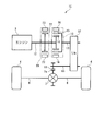
- the second driven portion (rear wheel 5) separate from the driven portion (front wheel 4) and the second driven portion (rear wheel).
- a second rotating machine 20 mechanically coupled to 5).
- the driven part and the second driven part can be driven separately by operating the first rotating machine and the second rotating machine.
- the invention according to claim 9 is the power plant 1A according to claim 8, further comprising a transmission 53 that performs a shift operation between the second rotor 15 of the first rotating machine 10 and the heat engine (engine 3). It is characterized by that.
- this power unit since it further includes a transmission that performs a speed change operation between the second rotor of the first rotating machine and the heat engine, the power of the heat engine is transmitted to the first rotating machine while shifting. be able to.
- the transmission 54 that performs a shift operation between the second rotating machine 20 and the second driven portion (rear wheel 5) is further provided. It is characterized by providing.
- the transmission further includes a transmission that performs a speed change operation between the second rotating machine and the second driven portion. Therefore, by appropriately setting the transmission ratio of the transmission, The rotating machine can be reduced in size and rotation. For example, by setting a large reduction gear ratio of the transmission, it is possible to set a small torque to be transmitted from the second rotating machine to the transmission, thereby reducing the size of the second rotating machine.
- the first rotor 14 of the first rotating machine 10 is mechanically connected to the heat engine (engine 3), and the second rotor 15 is It is mechanically connected to the driven part (front wheel 4).
- a power unit using the heat engine and the first rotating machine as a power source can be realized. Further, as described above, the relationship between the three electrical angular velocities and the three torques in the first rotating machine is the same as the relationship between the speed and torque in the three elements of the planetary gear device, so that the power of the heat engine is reduced. While being able to transmit in order of 1 rotor, a 2nd rotor, and a to-be-driven part, the transmission state can be changed.
- the invention according to claim 12 is the power plant 1C according to claim 11, further comprising a restraining device (second rotating machine 20) for restraining the rotation of the first rotor 14.
- the relationship between the three electrical angular velocities and the three torques in the first rotating machine are the same as the relationship between the speed and torque in the three elements of the planetary gear unit.
- a second rotating machine having a rotating shaft (input shaft 12) mechanically coupled to the heat engine (engine 3) and the first rotor 14 is provided. 20 is further provided.
- the second rotating machine having the rotating shaft mechanically coupled to the heat engine and the first rotor since the second rotating machine having the rotating shaft mechanically coupled to the heat engine and the first rotor is further provided, the heat engine and the first rotating machine are operated by operating the second rotating machine. In addition to the power of the first rotating machine, the power of the second rotating machine can be transmitted to the driven part, so that the driven part can be driven with a driving force larger than that of the power unit of claim 11. it can.
- the heat engine since the heat engine is further provided with the clutch that mechanically connects / disconnects between the first rotor of the first rotating machine and the rotating shafts of the second rotating machine and the heat engine, the heat engine stops. If the clutch is driven to the disengagement side and at least one of the first rotating machine and the second rotating machine is powered, the heat engine is stopped and the first rotating machine and / or the second rotating machine is stopped. The power of the machine can be transmitted to the driven part. Thereby, the driven part can be driven.
- the transmission 57 that performs a shift operation between the second rotor 15 of the first rotating machine 10 and the driven portion (front wheel 4) is further provided. It is characterized by providing.
- this power unit since it further includes a transmission that performs a transmission operation between the second rotor of the first rotating machine and the driven part, by appropriately setting the transmission ratio of this transmission, The first rotating machine and the second rotating machine can be reduced in size and rotation. For example, by setting a large reduction gear ratio of the transmission, the torque to be transmitted to the transmission via the first rotating machine and the second rotating machine can be set to a small value, whereby the first rotating machine and the first rotating machine A two-rotor can be reduced in size.
- a transmission 58 that performs a speed change operation between the rotation shaft (input shaft 12) of the second rotating machine 20 and the heat engine (engine 3). Is further provided.
- this power unit since it further includes a transmission that performs a speed change operation between the rotating shaft of the second rotating machine and the heat engine, the power of the heat engine is transmitted to the second rotating machine while shifting. Can do.
- the invention according to claim 17 is the power plant 1D according to claim 11, wherein the second driven part (rear wheel 5) separate from the driven part (front wheel 4) and the second driven part (rear wheel). And a second rotating machine 20 mechanically coupled to 5).
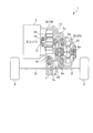
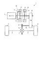
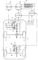
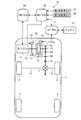
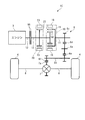
- FIG. 1 is a diagram illustrating a schematic configuration of a power unit according to a first embodiment of the present invention and a hybrid vehicle to which the power unit is applied. It is a figure which shows schematic structure of the power plant of 1st Embodiment. It is sectional drawing which shows typically schematic structure of a 1st rotary machine and a 2nd rotary machine.
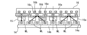
- FIG. 4 is a diagram schematically showing an annular cross section broken along the circumferential direction at the position of line AA in FIG. 3 in a straight line.
- FIG. 5 is a collinear chart showing an example of the relationship among a magnetic field electrical angular velocity ⁇ MFR, a first rotor electrical angular velocity ⁇ ER1, and a second rotor electrical angular velocity ⁇ ER2.
- FIG. 7 is a diagram for explaining an operation subsequent to FIG. 6.
- FIG. 8 is a diagram for explaining an operation subsequent to FIG. 7.
- FIG. 6 is a diagram for explaining the positional relationship between the armature magnetic pole and the soft magnetic core when the armature magnetic pole rotates by an electrical angle of 2 ⁇ from the state shown in FIG. 5. It is a figure for demonstrating operation
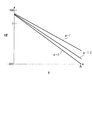
- FIG. 12 is a diagram for explaining an operation subsequent to FIG. 11. It is a speed alignment chart which shows an example of the relationship between three electrical angular velocities and three torques when the pole pair number ratio ⁇ in the first rotating machine of the first embodiment is an arbitrary value. It is a figure which shows the relationship between output ratio RW and reduction ratio R when the pole pair number ratio (alpha) in the 1st rotary machine of the power plant of 1st Embodiment is set to the value 1, the value 1.5, and the value 2.
- FIG. It is a figure which shows the modification of arrangement
- the power plant according to the first embodiment of the present invention will be described with reference to the drawings.
- the left side and the right side in FIGS. 1 to 3 are referred to as “left” and “right”, respectively.
- the power unit 1 of the present embodiment drives left and right front wheels 4 and 4 of a hybrid vehicle (hereinafter referred to as “vehicle”) 2.
- vehicle a hybrid vehicle
- a first rotating machine 10 and a second rotating machine 20 are provided.
- the engine 3 is connected to the first rotating machine 10, and the first rotating machine 10 and the second rotating machine 20 are connected to the gear mechanism 6, the differential gear mechanism 7, and the left and right drive shafts 8, 8. Are connected to the left and right front wheels 4, 4. Thereby, as described later, the power of the engine 3 and the power of the first rotating machine 10 and the second rotating machine 20 are transmitted to the front wheels 4 and 4.
- the vehicle 2 also includes left and right rear wheels 5 and 5 that are idle wheels.
- the engine 3 corresponds to a heat engine
- the front wheel 4 corresponds to a driven part.
- the engine 3 is a multi-cylinder internal combustion engine that uses gasoline as fuel, and its operation state is controlled by an ENG / ECU 29 described later.
- the two rotating machines 10 and 20 and the gear mechanism 6 are all housed in a drive system housing (none of which is shown) fixed to the cylinder block of the engine 3.
- the gear mechanism 6 includes first and second gear shafts 6a and 6b parallel to an output shaft 13 (to be described later) of the first rotating machine 10, and four gears provided on the output shaft 13 and the two gear shafts 6a and 6b. 6c to 6f.
- the gear 6c is concentrically fixed to the right end portion of the output shaft 13, and always meshes with the gear 6d.
- the gear 6d is concentrically and rotatably fitted to the first gear shaft 6a, and always meshes with a gear 6e fixed concentrically to the right end of the second gear shaft 6b in addition to the gear 6c. .
- the gear 6f is concentrically fixed to the left end portion of the second gear shaft 6b and always meshes with the gear 7a of the differential gear mechanism 7. With the above configuration, the rotation of the output shaft 13 is transmitted to the differential gear mechanism 7 via the gear mechanism 6.
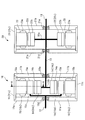
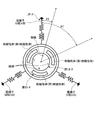
- FIG. 3 schematically shows a cross-sectional configuration of the first rotating machine 10 and the second rotating machine 20
- FIG. 4 shows a circle broken along the circumferential direction at the position of line AA in FIG. It is the figure which showed the cyclic
- the first rotating machine 10 includes a case 11 fixed to the drive train housing described above, an input shaft 12 whose left end is directly connected to the crankshaft of the engine 3, and a concentricity with the input shaft 12.
- Output shaft 13 (rotating shaft), a first rotor 14 accommodated in the case 11 and rotated integrally with the output shaft 13, and a second rotor 15 accommodated in the case 11 and rotated integrally with the input shaft 12.
- a stator 16 fixed to the inner peripheral surface of the peripheral wall 11 c of the case 11.
- the first rotor 14, the second rotor 15, and the stator 16 are arranged concentrically from the inner side to the outer side in the radial direction.
- the case 11 includes left and right side walls 11a and 11b and cylindrical peripheral walls 11c fixed to the outer peripheral ends of the side walls 11a and 11b.
- Bearings 11d and 11e are respectively attached to the center portions of the left and right side walls 11a and 11b, and the input shaft 12 and the output shaft 13 are rotatably supported by these bearings 11d and 11e, respectively. Further, the axial movement of the two shafts 12 and 13 is restricted by a thrust bearing (not shown) or the like.
- the first rotor 14 includes a rotating disc portion 14b concentrically fixed to the left end portion of the output shaft 13, a cylindrical ring portion 14c fixed to the outer end portion of the rotating disc portion 14b, and the like.
- the ring portion 14c is made of a soft magnetic material, and a permanent magnet array is provided on the outer peripheral surface thereof so as to face the iron core 16a of the stator 16 along the circumferential direction.
- the permanent magnet row is composed of eight permanent magnets 14 a (magnetic poles).
- These permanent magnets 14a have two mutually adjacent polarities, are arranged at equal intervals, and the length of each permanent magnet 14a in the axial direction is set to a predetermined length.
- the N pole and the S pole of the permanent magnet 14a are indicated as (N) and (S), respectively, and for the sake of easy understanding, other than the main configuration. (For example, the case 11) is not shown.
- the stator 16 generates a rotating magnetic field, and includes an iron core 16a and U-phase, V-phase, and W-phase coils 16c, 16d, and 16e (see FIG. 4) wound around the iron core 16a. is doing.
- the iron core 16a has a cylindrical shape in which a plurality of steel plates are laminated.
- the iron core 16a is fixed to the case 11 and has an axial length that is the same as that of the permanent magnet 14a.
- twelve slots 16b are formed on the inner peripheral surface of the iron core 16a, and these slots 16b extend in the axial direction and are arranged in the circumferential direction of the first main shaft 4 (hereinafter simply referred to as “circumferential direction”). Are lined up at regular intervals.
- the iron core 16a and the U-phase to W-phase coils 16c to 16e correspond to an armature and an armature array.
- U-phase to W-phase coils 16c to 16e are wound around the slot 16b by distributed winding (wave winding) and are electrically connected to a battery 33 (described later) via a 1ST / PDU 31 (described later). ing.
- the iron core 16a At the end on the first rotor 14 side, four magnetic poles are generated at equal intervals in the circumferential direction (see FIG. 6), and a rotating magnetic field by these magnetic poles rotates in the circumferential direction.
- the magnetic poles generated in the iron core 16a are referred to as “armature magnetic poles”.
- the polarities of the two armature magnetic poles adjacent to each other in the circumferential direction are different from each other.
- the N pole and S pole of the armature magnetic pole are also expressed as (N) and (S), respectively, similarly to the N pole and S pole of the permanent magnet 14a.
- the second rotor 15 includes a turntable portion 15b fixed to the right end portion of the input shaft 12, a support portion 15c extending from the outer end portion of the turntable portion 15b to the second rotating machine 20 side, and the support portion. It has a soft magnetic core row that is fixed to 15 c and is disposed between the permanent magnet row of the first rotor 14 and the iron core 16 a of the stator 16.
- This soft magnetic core array is composed of six soft magnetic cores 15a made of a soft magnetic material (for example, a laminate of steel plates).
- These soft magnetic cores 15a are arranged at equal intervals along the circumferential direction, and are provided so as to have a predetermined interval with respect to the permanent magnet 14a and the iron core 16a.
- the length of the soft magnetic core 15 a in the axial direction is set to the same length as the permanent magnet 14 a and the iron core 16 a of the stator 16.
- the operation principle of the first rotating machine 10 configured as described above will be described.
- ⁇ F represents the maximum value of the magnetic flux of the magnet magnetic pole.
- ⁇ ER1 is the first rotor electrical angle, and the rotational angle position of the specific permanent magnet 14a of the first rotor 14 with respect to the specific U-phase coil 16c (hereinafter referred to as “reference coil”) is converted into an electrical angle position. Value. That is, the first rotor electrical angle ⁇ ER1 is a value obtained by multiplying the rotation angle position of this specific permanent magnet 14a by the number of pole pairs (value 2) of the armature magnetic poles.
- ⁇ ER2 is the second rotor electrical angle, which is a value obtained by converting the rotation angle position of the specific soft magnetic core 15a of the second rotor 15 with respect to the reference coil into the electrical angle position. That is, the second rotor electrical angle ⁇ ER2 is a value obtained by multiplying the rotational angle position of the specific soft magnetic core 15a by the number of pole pairs (value 2) of the armature magnetic poles.
- ⁇ ER1 in the above equations (33) to (35) is the first rotor electrical angular velocity, and is a value obtained by converting the time differential value of ⁇ ER1, that is, the angular velocity of the first rotor 14 with respect to the stator 16 into the electrical angular velocity.
- ⁇ ER2 is the second rotor electrical angular velocity, and is a value obtained by converting the time differential value of ⁇ ER2, that is, the angular velocity of the second rotor 15 with respect to the stator 16 into the electrical angular velocity.
- the current flowing through the U-phase coil 16c (hereinafter, “ Iu, current flowing through the V-phase coil 16d (hereinafter referred to as “V-phase current”) Iv, and current flowing through the W-phase coil 16e (hereinafter referred to as “W-phase current”) Iw are respectively expressed by the following equations: (36) to (38).
- I represents the amplitude (maximum value) of the current flowing through the U-phase to W-phase coils 16c to 16e.
- the vector of the rotating magnetic field of the stator 16 with respect to the reference coil is clear from the above-described equations (24) and (25).
- the electrical angle position (hereinafter referred to as “magnetic field electrical angle position”) ⁇ MFR is expressed by the following formula (39)
- the electrical angular velocity (hereinafter referred to as “magnetic field electrical angular velocity”) ⁇ MFR of the rotating magnetic field with respect to the stator 16 is expressed by the following formula (40). ).
- the driving equivalent torque TSE when the equivalent torque to the electric power supplied to the stator 16 and the magnetic field electrical angular velocity ⁇ MFR is the driving equivalent torque TSE, the driving equivalent torque TSE and the torque transmitted to the first rotor 14 (hereinafter referred to as “first”
- first The relationship between TR1 (referred to as “rotor transmission torque”) and torque (hereinafter referred to as “second rotor transmission torque”) TR2 transmitted to the second rotor 15 is apparent from the above-described ratio of the number of elements and the above-described equation (32). Thus, it is represented by the following formula (41).
- the relationship between the three electrical angular velocities ⁇ MFR, ⁇ ER1, and ⁇ ER2 expressed by the equation (40) and the relationship between the three torques TSE, TR1, and TR2 expressed by the equation (41) are as follows. This is the same as the relationship between the rotational speed and torque in the sun gear, ring gear and carrier (hereinafter referred to as “three elements of the planetary gear device”) of the planetary gear device having a gear ratio of 1: 2.
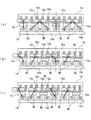
- the positions of the armature magnetic poles having the same polarity are made to coincide with the center of each permanent magnet 14a whose center coincides with the soft magnetic core 15a in the circumferential direction, and
- the polarity is set to be different from the polarity of the magnetic pole of the permanent magnet 14a.
- the second rotor 15 having the soft magnetic core 15a is disposed between the stator 16 and the first rotor 14.
- Each of the soft magnetic cores 15a is magnetized by the armature magnetic poles and the magnet magnetic poles, and the soft magnetic cores 15a are provided at an interval, so that the armature magnetic poles, the soft magnetic cores 15a, and the magnets are provided.
- Magnetic field lines ML that connect the magnetic poles are generated.
- the magnetic field lines ML connect the armature magnetic pole, the soft magnetic core 15a, and the magnet magnetic pole, whose positions in the circumferential direction coincide with each other, and these armature magnetic pole and soft magnetic core. 15a and the magnet magnetic poles are generated so as to connect the armature magnetic poles adjacent to each other in the circumferential direction, the soft magnetic core 15a and the magnet magnetic poles.
- the magnetic lines of force ML are linear, there is no magnetic force that rotates the soft magnetic core 15a in the circumferential direction.
- the magnetic lines of force ML are bent, and accordingly, the magnetic lines of force ML are linear.
- the magnetic force acts on the soft magnetic core 15a.
- the magnetic force line ML protrudes in the direction opposite to the rotating direction of the rotating magnetic field (hereinafter referred to as “magnetic field rotating direction”) with respect to the straight line connecting the armature magnetic pole and the magnet magnetic pole. Therefore, the magnetic force caused by the magnetic field lines ML acts to drive the soft magnetic core 15a in the magnetic field rotation direction.
- the soft magnetic core 15a is driven in the magnetic field rotation direction and rotates toward the position shown in FIG. 6C, and the second rotor 15 provided with the soft magnetic core 15a also moves in the magnetic field rotation direction. Rotate.
- the broken lines in FIGS. 6B and 6C indicate that the magnetic flux amount of the magnetic field lines ML is extremely small, and the magnetic connection between the armature magnetic pole, the soft magnetic core 15a, and the magnetic pole is weak. . The same applies to other drawings described later.
- the magnetic force line ML bends in the direction opposite to the magnetic field rotating direction in the soft magnetic core 15 a ⁇ the magnetic force line ML becomes linear.
- the magnetic force acts on the soft magnetic core 15a ⁇ the operation of the soft magnetic core 15a and the second rotor 15 rotating in the direction of the magnetic field rotation is shown in FIGS. 7 (a) to 7 (d) and FIG. 8 (a), Repeated as shown in (b).
- the power supplied to the stator 16 by the action of the magnetic force due to the magnetic field lines ML as described above. Is converted into power, and the power is output from the second rotor 15.
- the center of the leftmost soft magnetic core 15a in the figure and the center of the leftmost permanent magnet 14a in the figure are the same.
- the centers of the soft magnetic cores 15a that are three to the right of the soft magnetic core 15a and the centers of the permanent magnets 14a that are four to the right of the permanent magnet 14a are circumferentially aligned with each other in the circumferential direction. In a state where they are coincident with each other, a rotating magnetic field is generated to rotate leftward in the figure.
- the positions of the armature magnetic poles having the same polarity are made to coincide with the center of each permanent magnet 14a whose center coincides with the soft magnetic core 15a in the circumferential direction, and
- the polarity is set to be different from the polarity of the magnetic pole of the permanent magnet 14a.
- the magnetic force lines ML connect the armature magnetic pole, the soft magnetic core 15a, and the magnet magnetic pole whose positions in the circumferential direction coincide with each other.
- the armature magnetic pole, the soft magnetic core 15a and the magnet magnetic pole are generated so as to connect the armature magnetic pole, the soft magnetic core 15a and the magnet magnetic pole adjacent to each other in the circumferential direction.
- the magnetic lines of force ML are linear, there is no magnetic force that rotates the soft magnetic core 15a in the circumferential direction.
- the magnetic field line ML is bent, and accordingly, the magnetic field line ML becomes a straight line.
- the magnetic force acts on the permanent magnet 14a.
- the permanent magnet 14a since the permanent magnet 14a is in a position advanced in the magnetic field rotation direction from the extension line of the armature magnetic pole and the soft magnetic core 15a connected to each other by the magnetic force line ML, the magnetic force due to the magnetic force line ML is It acts to position the permanent magnet 14a on the extension line. That is, it acts to drive the permanent magnet 14a in the direction opposite to the magnetic field rotation direction.
- the permanent magnet 14a is driven in the direction opposite to the magnetic field rotation direction and rotates toward the position shown in FIG. 10C, and the first rotor 14 provided with the permanent magnet 14a is also opposite to the magnetic field rotation direction. Rotate in the direction.
- the electric power supplied to the stator 16 is driven by the action of the magnetic force caused by the magnetic field lines ML as described above.
- the power is output from the first rotor 14.
- the first rotating machine 10 of the present embodiment when a rotating magnetic field is generated by supplying power to the stator 16, magnetic field lines that connect the magnetic pole, the soft magnetic core 15 a, and the armature magnetic pole described above. ML is generated, and the electric power supplied to the armature is converted into power by the action of the magnetic force generated by the magnetic field lines ML, and the power is output from the first rotor 14 and the second rotor 15.
- the relationship shown in the above-described equation (40) is established between the magnetic field electrical angular velocity ⁇ MFR and the first and second rotor electrical angular velocities ⁇ ER1 and ⁇ ER2, and the driving equivalent torque TSE, the first and second equivalent torques Between the rotor transmission torques TR1 and TR2, the relationship shown in the aforementioned equation (41) is established.
- the relationship between these three torques TSE, TR1 and TR2 and the relationship between the electrical angular velocities ⁇ MFR, ⁇ ER1 and ⁇ ER2 are the same as the relationship between the torque and the rotational speed in the three elements of the planetary gear unit.
- the first rotor 14 and / or the second rotor 15 are moved with respect to the stator 16.
- the stator 16 When rotated, the stator 16 generates power and generates a rotating magnetic field.
- a magnetic force line ML that connects the magnet magnetic pole, the soft magnetic material, and the armature magnetic pole is generated, and the relationship between the electrical angular velocity shown in the equation (40) and the equation (41) is shown by the action of the magnetic force by the magnetic force line ML.
- a torque relationship is established.
- the power generation equivalent torque TGE the power generation equivalent torque TGE and the first and second rotor transmission torques TR1 and TR2 are also represented by the formula (41 ) Is replaced by “TGE”.
- the relationship between the three torques and the relationship between the three electrical angular velocities are the same as the relationship between the torque and the rotation speed in the three elements of the planetary gear device.
- the first rotating machine 10 can be operated with the same operating characteristics as the planetary gear device.
- the second rotating machine 20 is composed of a DC brushless motor. As shown in FIG. 3, the second rotating machine 20 is housed in the case 21 fixed to the drive system housing described above, and concentrically with the output shaft 13. A fixed rotor 22 and a stator 23 fixed to the inner peripheral surface of the peripheral wall 21c of the case 21 are provided.
- the case 21 includes left and right side walls 21a and 21b and cylindrical peripheral walls 21c fixed to the outer peripheral ends of the side walls 21a and 21b.
- Bearings 21d and 21e are respectively attached to the inner ends of the left and right side walls 21a and 21b, and the output shaft 13 is rotatably supported by these bearings 21d and 21e.
- the rotor 22 includes a turntable portion 22a concentrically fixed to the output shaft 13, a cylindrical ring portion 22b fixed to the outer end portion of the turntable portion 22a, and the like.
- the ring portion 22b is made of a soft magnetic material, and a permanent magnet row is provided along the circumferential direction on the outer peripheral surface thereof.
- This permanent magnet row is composed of a predetermined number of permanent magnets 22c, and these two permanent magnets 22c are arranged at the same predetermined angle intervals and adjacent to each other with different polarities.
- the stator 23 has a plurality of armatures 23 a provided along the circumferential direction on the inner peripheral surface of the peripheral wall 21 c of the case 21. These armatures 23a generate rotating magnetic fields, are disposed at the same predetermined angle intervals, and are electrically connected to the battery 33 via 2ND / PDU 32 described later.
- the power unit 1 includes an ENG / ECU 29 for mainly controlling the engine 3, a MOT / ECU 30 for mainly controlling the first rotating machine 10 and the second rotating machine 20, and the like. It has.
- Each of these ECUs 29 and 30 is constituted by a microcomputer (all not shown) including a RAM, a ROM, a CPU, an I / O interface, and the like.
- the ENG / ECU 29 is connected to various sensors (not shown) such as a crank angle sensor, a drive shaft rotational speed sensor, an accelerator opening sensor, and a vehicle speed sensor.
- the ENG • ECU 29 determines the engine speed NE, the rotational speed of the drive shaft 8 (hereinafter referred to as “drive shaft rotational speed”) ND, the accelerator opening AP (the operation of an accelerator pedal (not shown)) based on the detection signals of these various sensors. Volume), vehicle speed VP, and the like, and the operation of the engine 3 is controlled by driving a fuel injection valve, a spark plug, and the like according to these parameters.
- the ENG • ECU 29 is electrically connected to the MOT • ECU 30 and transmits / receives various data such as the engine rotational speed NE and the drive shaft rotational speed ND to / from the MOT • ECU 30.
- the 1ST / PDU 31, 2 ND / PDU 32, the first rotation angle sensor 35 and the second rotation angle sensor 36 are connected to the MOT / ECU 30.
- the 1ST / PDU 31 includes an electric circuit including an inverter and the like, and is connected to the first rotating machine 10 and the battery 33.
- the 2ND / PDU 32 includes an electric circuit including an inverter, and is connected to the second rotating machine 20 and the battery 33.
- the first rotation angle sensor 35 detects the rotation angle of the first rotor 14 with respect to the stator 16 and outputs a detection signal representing it to the MOT / ECU 30.
- the second rotation angle sensor 36 detects the rotation angle of the second rotor 15 with respect to the stator 16 and outputs a detection signal representing the rotation angle to the MOT / ECU 30.
- the MOT • ECU 30 controls the operating states of the two rotating machines 10 and 20 as described below in accordance with detection signals from these sensors and various data from the ENG • ECU 29 described above. *
- the MOT • ECU 30 is operated when a predetermined engine start condition is satisfied (for example, when an ignition switch (not shown) is switched from the OFF state to the ON state).
- the electric power of the battery 33 is supplied to the first rotating machine 10 via the 1ST / PDU 31 and a rotating magnetic field is generated in the stator 16.
- the first rotor 14 is mechanically connected to the front wheel 4 and the second rotor 15 is mechanically connected to the crankshaft of the engine 3.
- the rotational resistance of the first rotor 14 is much higher than that of the second rotor 15, and as a result, the second rotor 15 moves in the rotating direction of the rotating magnetic field while the first rotor 14 is stopped. Will be driven. As a result, the second rotor 15 is driven with the rotation of the rotating magnetic field, whereby the engine 3 can be started.
- the start control is performed. Is executed. First, since the output shaft 13, that is, the first rotor 14 is in a rotation stopped state while the vehicle is stopped, all the power generated by the engine 3 is transmitted to the stator 16 of the first rotating machine 10 through the magnetic lines of force, By generating a rotating magnetic field, an induced electromotive force (that is, a counter electromotive voltage) is generated.
- a predetermined start condition for example, when a brake pedal (not shown) is not operated and the accelerator opening AP is equal to or greater than a predetermined value
- the MOT • ECU 30 regenerates the induced electromotive force generated in the stator 16 by controlling the current supplied to the stator 16, and all the regenerative power is supplied to the second rotating machine 20 via the 1ST • PDU 31 and the 2ND • PDU 32. To supply. As a result, the output shaft 13 is driven by the rotor 22 of the second rotating machine 20, and the front wheels 4 and 4 are driven, whereby the vehicle 2 starts. After starting the vehicle 2, the MOT / ECU 30 controls the regenerative power in the first rotating machine 10 to gradually decrease as the vehicle speed increases, and at the same time controls the regenerative power to be supplied to the second rotating machine 20. .
- shift control is executed when the engine is running and running.
- this speed change control according to the operating state of the engine 3 (for example, the engine speed NE and the accelerator pedal opening AP) and / or the traveling state of the vehicle 2 (for example, the vehicle speed VP),
- the first rotating machine 10 is controlled so that the ratio between the power transmitted to the front wheels 4 via the first rotor 14 and the power regenerated as electric power by the first rotating machine 10 is changed.
- the second rotating machine 20 is controlled.
- the first rotating machine 10 can be operated with the same operating characteristics as the planetary gear device.
- the first rotating machine 10 is controlled as described above, and the first rotating machine 10
- the second rotating machine 20 is controlled by supplying the regenerative power at 10 to the second rotating machine 20, if the electrical loss is ignored, the first rotating machine 10 and the second rotating machine 20 While transmitting all the power of the engine 3 to the front wheels 4, the ratio between the rotation speed of the second rotor 15 and the rotation speed of the output shaft 13, in other words, the ratio between the engine rotation speed NE and the drive shaft rotation speed ND is arbitrarily changed. can do. That is, by controlling the two rotating machines 10 and 20, a function as an automatic transmission can be realized.
- the power regeneration in the first rotating machine 10 is stopped.
- the rotational speed of the rotating magnetic field of the stator 16 is controlled to a value of 0 by supplying a lock current to the stator 16 or executing interphase short-circuit control in the first rotating machine 10.
- all power of the engine 3 can be transmitted to the front wheels 4 via magnetism as long as it is within the range in which magnetic transmission is possible, so that the regenerative power in the first rotating machine 10 is transmitted to the 2ND PDU 32.
- the power transmission efficiency can be improved as compared with the case where control is performed so as to supply the second rotating machine 20 via the control.
- assist control is executed. Specifically, by supplying the electric power in the battery 33 to the first rotating machine 10 and / or the second rotating machine 20, the power of the first rotating machine 10 and / or the second rotating machine 20 and the engine 3 The first rotating machine 10 and / or the second rotating machine 20 is controlled so that power is transmitted to the front wheels 4. Thereby, in addition to the engine 3, it is possible to perform assist running or start using the first rotating machine 10 and / or the second rotating machine 20 as a power source.
- the rotating machine start control is executed. Specifically, the electric power of the battery 33 is simultaneously supplied to the first rotating machine 10 and the second rotating machine 20 while the engine 3 is stopped, and the two rotating machines 10 and 20 are driven simultaneously. At that time, the output shaft 13 begins to rotate simultaneously with the second rotating machine 20 starting to rotate. In the first rotating machine 10, the rotational resistance of the second rotor 15 connected to the stopped engine 3 is detected.
- the first rotor 14 can be driven by generating a rotating magnetic field in the stator 16, and the vehicle 2 can be started by the power of the first rotating machine 10 and the second rotating machine 20.
- a device for locking the engine 3 or increasing the rotational resistance may be provided.
- the vehicle 2 can be driven using the engine 3, the first rotating machine 10, and the second rotating machine 20 as power sources.
- the first rotating machine 10 may be configured to include only one soft magnetic material row, the first rotating machine 10 can be reduced in size and the manufacturing cost can be reduced accordingly.
- the power unit 1 itself can be downsized, the manufacturing cost can be reduced, and the degree of design freedom can be increased.
- the three electrical angular velocities ⁇ MFR, ⁇ ER1, and ⁇ ER2 are determined depending on how the pole pair number ratio ⁇ in the first rotating machine 10, that is, the pole number ratio m is set.
- the relationship between the three torques TSE, TR1, and TR2 can also be set freely. As a result, the degree of freedom in design can be further increased.
- the pole pair number ratio ⁇ of the first rotating machine 10 is set to an arbitrary value other than the value 1 and the driving wheels are directly connected to the output shaft 13.
- the electrical angular velocity of the input shaft 12, that is, the second rotor 15, is ⁇ ENG
- the electrical angular velocity of the rotating magnetic field of the stator 16 is ⁇ MG1
- the electrical angular velocity ⁇ OUT of the output shaft 13, that is, the first rotor 14 The relationship is as shown in FIG. 13, for example, and the following equation (42) is established.
- the torque input from the engine 3 to the input shaft 12 is the engine torque TENG
- the torque equivalent to the regenerative electric power of the stator 16 and the electric angular velocity ⁇ MG1 of the rotating magnetic field is the first rotating machine torque TMG1
- the torque is supplied to the second rotating machine 20.
- the torque equivalent to the supplied electric power and the electrical angular velocity ⁇ MG2 is the second rotating machine torque TMG2
- the torque as the reaction force that the driving wheel receives from the road surface due to the transmission torque to the driving wheel is the driving torque TOUT, (43) and (44) are established, and the relationship between these torques is as shown in FIG.
- the upward torque in FIG. 13 is represented by a positive value.
- the change amount ⁇ TMG1 of the first rotating machine torque TMG1 when the pole pair number ratio ⁇ is changed from the first predetermined value ⁇ 1 to the second predetermined value ⁇ 2 is expressed by the following formula (49 ).
- the change amount ⁇ TMG2 of the second rotating machine torque TMG2 when the pole pair number ratio ⁇ is changed from the first predetermined value ⁇ 1 to the second predetermined value ⁇ 2 is expressed by the following equation (50 ).
- the pole-to-log ratio ⁇ is set to the first predetermined value ⁇ 1.
- the absolute values of the first and second rotating machine torques TMG1, TMG2 are reduced. That is, it can be seen that the first rotating machine 10 and the second rotating machine 20 can be reduced in size by setting the pole pair number ratio ⁇ to a larger value.
- the output ratio RW is expressed by the following formula ( 52).
- the output ratio RW is reduced by changing the pole pair number ratio ⁇ from the first predetermined value ⁇ 1 to the second predetermined value ⁇ 2, as is apparent from the above equation (58). It can be seen that the transmission power WMG can be reduced. Further, in the above-described equation (55), the relationship between the output ratio RW and the reduction ratio R when the pole pair number ratio ⁇ is set to the value 1, the value 1.5, and the value 2 is as shown in FIG. As is apparent from FIG. 14, it is understood that the transmission power WMG can be reduced in almost the entire reduction ratio R by setting the pole pair number ratio ⁇ to a larger value.
- 1st Embodiment is an example which applied the power plant 1 of this invention to the vehicle 2 provided with the front wheel 4 as a to-be-driven part
- the power plant of this invention is not restricted to this,
- a ship and an aircraft It is applicable to various industrial equipment such as.
- a portion that generates propulsive force such as a screw corresponds to a driven part
- the power unit is applied to an aircraft, propulsion of a propeller, a rotor, and the like.
- a portion that generates a force corresponds to a driven portion.
- 1st Embodiment is an example using the internal combustion engine which uses gasoline as a fuel as a heat engine
- the heat engine of this invention is not restricted to this, The apparatus which changes heat energy into mechanical energy continuously If it is.
- an external combustion engine such as an internal combustion engine or a Stirling engine using light oil or natural gas as fuel may be used as the heat engine.
- the number of armature magnetic poles is “4”, the number of magnetic poles is “8”, and the number of soft magnetic cores 15 a as soft magnetic bodies is “6”.
- the number of armature magnetic poles, the number of magnetic poles, and the number of soft magnetic bodies in the first rotating machine of the present invention are not limited to these values, and the number of armature magnetic poles and the number of magnetic poles are not limited to these values.
- the pole number ratio m is a positive number other than 1
- 1st Embodiment is an example using the magnetic pole of the permanent magnet 14a as a magnetic pole of the 1st rotor 14, the armature row
- 1st Embodiment is an example using MOT * ECU30, 1ST * PDU31, and 2ND * PDU32 as a control means which controls the driving
- the control means for controlling the machine 10 and the second rotating machine 20 is not limited to this, and any means that can control the operation of these rotating machines 10 and 20 may be used.
- an electric circuit equipped with a microcomputer may be used as a control means for controlling the two rotating machines 10 and 20.
- the first embodiment is an example in which the first rotating machine 10 and the second rotating machine 20 are arranged side by side on the output shaft 13 in the axial direction.
- the arrangement of the first rotating machine 10 and the second rotating machine 20 is as follows. Not limited to this.
- both may be arranged side by side in the radial direction so that the first rotating machine 10 is located outside the second rotating machine 20. If it does in this way, the size of the direction of an axis of two rotating machines 10 and 20 can be reduced, and the freedom degree of design of power unit 1 can be raised.
- the first rotor 14 of the first rotating machine 10 and the rotor 22 of the second rotating machine 20 may be arranged on separate axes.
- the hatching of the cross section is omitted for easy understanding.
- the rotor 22 is provided not on the output shaft 13 but on the first gear shaft 6a. If it does in this way, in arrangement of two rotating machines 10 and 20, the freedom degree of design of power unit 1 can be raised.
- a transmission 50 may be provided instead of the gear mechanism 6.
- the speed change device 50 changes the reduction ratio between the output shaft 13 and the front wheels 4 stepwise or steplessly, and the speed change operation is controlled by the MOT • ECU 30.
- a stepped automatic transmission with a torque converter, a belt-type continuously variable transmission, a toroidal continuously variable transmission, and an automatic MT the clutch connecting / disconnecting operation and Any one of the stepped automatic transmissions for performing the shift operation is appropriately used.
- the transmission is transmitted to the transmission 50 via the first rotating machine 10 and the second rotating machine 20.
- the power torque can be set small, whereby the first rotating machine 10 and the second rotating machine 20 can be reduced in size.
- the rotational speed of the first rotating machine 10 and the second rotating machine 20 can be reduced by setting the reduction ratio for the high vehicle speed and high load range in the transmission 50 small.
- the transmission 51 may be provided in the middle of the input shaft 12 extending between the engine 3 and the second rotor 15.
- the transmission 51 changes the speed increase ratio between the engine 3 and the second rotor 15 stepwise or steplessly, and the gear change operation is controlled by the MOT / ECU 30.
- any one of a stepped automatic transmission with a torque converter, a belt-type continuously variable transmission, a toroidal continuously variable transmission, an automatic MT, or the like is used as appropriate. It is done.
- the torque to be transmitted to the final reduction gear side via the first rotating machine 10 and the second rotating machine 20 can be set small, and thereby the first rotating machine 10 and the second rotating machine 20 can be reduced in size. it can.
- the rotational speed of the first rotating machine 10 and the second rotating machine 20 can be reduced by setting the speed increasing ratio for the high vehicle speed / high load range in the transmission 51 to be small (or 1: 1). it can.
- the position of the gear mechanism 6 is changed between the first rotor 14 and the rotor 22 of the output shaft 13 and the gear of the output shaft 13 is changed.
- a transmission 52 may be provided between the mechanism 6 and the rotor 22.
- the speed change device 52 changes the reduction ratio between the rotor 22 and the gear 6c stepwise or steplessly, and the speed change operation is controlled by the MOT • ECU 30.
- the transmission device 52 as in the transmission device 50 described above, any of a stepped automatic transmission device with a torque converter, a belt-type continuously variable transmission device, a toroidal continuously variable transmission device, an automatic MT, etc. Used.
- the torque to be transmitted from the second rotating machine 20 to the front wheels 4 can be set small.
- the 2nd rotary machine 20 can be reduced in size.
- the speed of the second rotating machine 20 can be reduced by setting the reduction ratio for the high vehicle speed and high load range in the transmission 52 small, thereby improving the driving efficiency as described above.
- the life can be extended.
- the power unit 1A is different from the power unit 1 of the first embodiment in that the second rotating machine 20 is used as a power source for driving the rear wheels. Since it is configured in substantially the same manner as the power unit 1 of the first embodiment, the following description will focus on differences from the power unit 1 of the first embodiment, and the same reference numerals are assigned to the same configuration, and Description is omitted.
- the gear 6d on the first gear shaft 6a is always meshed with the gear 7a of the differential gear mechanism 7, whereby the output shaft 13 is rotated by the gears 6c, 6d and the differential gear mechanism 7. Is transmitted to the front wheels 4 and 4.
- the second rotating machine 20 is connected to the left and right rear wheels 5 and 5 via a differential gear mechanism 25, left and right drive shafts 26, 26, and the like.
- the power of the rotating machine 20 is transmitted to the rear wheels 5 and 5 (second driven part).
- the rotor 22 of the second rotating machine 20 is concentrically fixed to the left end portion of the gear shaft 24, and a gear 24a is concentrically fixed to the gear shaft 24 at the right end portion of the gear shaft 24.
- the gear 24a is always meshed with the gear 25a of the differential gear mechanism 25.
- the same operational effects as those of the power plant 1 of the first embodiment can be obtained.
- the vehicle 2 when the vehicle 2 starts, by supplying the electric power regenerated by the first rotating machine 10 to the second rotating machine 20, the vehicle 2 can start in an all-wheel drive state.
- the startability on a low ⁇ road can be improved.
- traveling stability on a low ⁇ road can be improved.
- a transmission 53 is provided in the middle of the input shaft 12 extending between the engine 3 and the second rotor 15, and the transmission 54 is connected to a gear. It may be provided between the gear 24 a of the shaft 24 and the rotor 22.
- the speed change device 53 changes the speed increase ratio between the engine 3 and the second rotor 15 stepwise or steplessly, and the speed change operation is controlled by the MOT • ECU 30.
- the transmission 54 changes the reduction ratio between the second rotating machine 20 and the rear wheel 5 stepwise or steplessly, and the speed change operation is controlled by the MOT / ECU 30.
- the transmissions 53 and 54 as in the transmission 50 described above, any of a stepped automatic transmission with a torque converter, a belt-type continuously variable transmission, a toroidal continuously variable transmission, an automatic MT, etc. Used as appropriate.
- the speed of the first rotating machine 10 can be reduced by setting the speed increasing ratio for the high vehicle speed / high load range in the transmission 53 to be small (or 1: 1). Accordingly, as described above, in the first rotating machine 10, the field rotation speed can be reduced, so that the energy loss can be reduced, the transmission efficiency can be improved, and the life can be extended.
- the torque generated by the second rotating machine 20 can be set to be small. It can be downsized.
- the rotational speed of the second rotating machine 20 can be reduced by setting the reduction ratio for the high vehicle speed / high load range in the transmission 54 small.
- the two transmissions 53 and 54 are provided in the power unit 1A, but one of the transmissions 53 and 54 may be omitted.
- the power unit 1B differs from the power unit 1 of the first embodiment in that the second rotating machine 20 and the 2ND / PDU 32 are omitted and an electromagnetic brake 55 is added.
- the rest of the configuration is substantially the same as that of the power unit 1 according to the first embodiment. Therefore, the following description will focus on the points different from the power unit 1 according to the first embodiment. The description is omitted.
- the gear 6d on the first gear shaft 6a is always meshed with the gear 7a of the differential gear mechanism 7, whereby the output shaft 13 Is transmitted to the front wheels 4 and 4 via the gears 6 c and 6 d and the differential gear mechanism 7.
- the electromagnetic brake 55 (stopping device) is provided between the first rotating machine 10 of the input shaft 12 and the engine 3 and is electrically connected to the MOT / ECU 30.
- the electromagnetic brake 55 is switched between the ON / OFF states by the MOT / ECU 30 and permits the rotation of the input shaft 12 when in the OFF state, and stops the rotation of the input shaft 12 when in the ON state.
- the electromagnetic brake 55 is controlled to be in an ON state only at the time of rotating machine start control described later, and is held in an OFF state in various controls other than the rotating machine start control.
- engine start control when the engine is stopped and the vehicle is stopped, the engine 3 is started by the power of the first rotating machine 10 when the aforementioned predetermined engine start condition is satisfied. Specifically, when a predetermined start condition is established, the power of the battery 33 is supplied to the first rotating machine 10 via the 1ST / PDU 31. Accordingly, as described above, the second rotor 15 is driven while the first rotor 14 is stopped, and as a result, the engine 3 is started.
- the start control is executed when the predetermined start condition described above is satisfied.
- the first rotating machine 10 regenerates the power of the engine 3 as electric power (that is, generates electric power). Then, after the start of power regeneration, the first rotating machine 10 is controlled such that the regenerative power decreases. Thereby, the vehicle 2 can be started by the power of the engine 3 while avoiding engine stall.
- engine power distribution control is executed while the engine is running.
- the first rotor of the motive power of the engine 3 depends on the operating state of the engine 3 (such as the engine speed NE and the accelerator pedal opening AP) and / or the traveling state of the vehicle 2 (such as the vehicle speed VP).
- the first rotating machine 10 is controlled so as to change the ratio between the power transmitted to the front wheels 4 via 14 and the power regenerated as electric power by the first rotating machine 10. Thereby, the vehicle 2 can be made to travel while appropriately controlling the regenerative power according to the operating state of the engine 3 and / or the traveling state of the vehicle 2.
- the first rotating machine 10 is controlled so that the rotational speed of the rotating magnetic field of the stator 16 becomes zero.
- the power of the engine 3 can be magnetically transmitted to the front wheels 4 via the second rotor 15 and the first rotor 14 as long as the power is within a range where magnetic transmission is possible.
- the assist control is executed when the aforementioned predetermined assist condition is satisfied. Specifically, the electric power in the battery 33 is supplied to the first rotating machine 10, and the first rotating machine 10 is controlled so that the front wheels 4 are driven by the power of the engine 3 and the first rotating machine 10. As a result, in addition to the engine 3, the first rotating machine 10 can be used for assisting with the power source.
- the electromagnetic brake 55 is turned on, the rotation of the second rotor 15 is stopped, and the power of the battery 33 is reduced.
- the first rotating machine 10 is subjected to power running control. Accordingly, the front wheel 4 can be driven by the first rotating machine 10 while the engine 3 is stopped, and the vehicle 2 can be started. As a result, fuel consumption can be improved.
- the power unit 1C is different from the power unit 1 of the first embodiment in the arrangement of the first rotating machine 10 and the second rotating machine 20, and the rest are the first embodiment. Since the power unit 1 is configured in substantially the same manner, the description below will focus on the differences from the power unit 1 of the first embodiment, and the same reference numerals will be assigned to the same components and description thereof will be omitted. .
- the second rotating machine 20 is disposed between the engine 3 and the first rotating machine 10, and the rotor 22 is concentrically fixed to a predetermined portion of the input shaft 12 (rotating shaft). Further, in the first rotating machine 10, the first rotor 14 is concentrically fixed to the right end portion of the input shaft 12 downstream of the rotor 22, and the second rotor 15 is concentrically fixed to the left end portion of the output shaft 13. Yes. Thereby, when the second rotor 15 is rotating during the operation of the first rotating machine 10, the power is transmitted to the front wheels 4, 4.
- the start control is executed when the predetermined start condition described above is satisfied. Specifically, while the vehicle is stopped, the power of the engine 3 is transmitted to the input shaft 12 and the first rotor 14 of the first rotating machine 10 is driven. In this state, by controlling the first rotating machine 10, the first rotating machine 10 executes power regeneration, and when the regenerative power is supplied to the second rotating machine 20, the rotor 22 of the second rotating machine 20 The first rotor 14 is driven to generate energy circulation. In this state, when the regenerative power in the first rotating machine 10 is controlled to decrease, the second rotor 15 of the first rotating machine 10 rotates, the output shaft 13 is driven, and the front wheels 4 and 4 are driven. Then, the vehicle 2 starts.
- the regenerative electric power in the first rotating machine 10 is further controlled to decrease, and the second rotation is performed after the magnetic field rotation direction of the stator 16 of the first rotating machine 10 has shifted from reverse rotation to normal rotation.
- the vehicle speed increases by regeneratively controlling the machine 20 and powering the first rotating machine 10.
- shift control is executed when the engine is running and running.
- the input shaft 12 of the power of the engine 3 depends on the operating state of the engine 3 (engine speed NE, accelerator pedal opening AP, etc.) and / or the traveling state of the vehicle 2 (vehicle speed VP, etc.).
- the second rotating machine 20 is controlled so that the ratio of the power transmitted to the first rotor 14 via the power and the power regenerated as electric power by the second rotating machine 20 is changed.
- the first rotating machine 10 is controlled.
- the second rotating machine 20 is controlled as described above, and the second rotation is performed.
- the first rotating machine 10 When the first rotating machine 10 is controlled by supplying the regenerative power from the machine 20 to the first rotating machine 10, the electrical loss can be ignored via the first rotating machine 10 and the second rotating machine 20.
- the ratio between the rotational speed of the input shaft 12 and the rotational speed of the output shaft 13, in other words, the ratio of the engine rotational speed NE and the drive shaft rotational speed ND is arbitrarily changed while transmitting all the power of the engine 3 to the front wheels 4. can do. That is, by controlling the two rotating machines 10 and 20, a function as an automatic transmission can be realized.
- the shift control when the above-described predetermined power transmission condition is satisfied, power regeneration in the first rotating machine 10 is stopped and a lock current is supplied to the stator 16 or an interphase short circuit in the first rotating machine 10.
- the rotational speed of the rotating magnetic field of the stator 16 is controlled to a value of 0 by executing control or the like.
- the power of the engine 3 can be transmitted to the front wheels 4 via magnetism as long as it is within the range of magnetic transmission, so that the regenerative power in the first rotating machine 10 is transmitted via the 2ND / PDU 32. Power transmission efficiency can be improved as compared with the case where control is performed so that the second rotating machine 20 is supplied.
- the first rotating machine 10 and / or the second rotating machine when the engine is running (including during deceleration fuel cut operation) and the remaining charge SOC of the battery 33 is equal to or less than the predetermined value SOC_REF, the first rotating machine 10 and / or the second rotating machine.
- the regenerative power in 20 is controlled, and charging control to the battery 33 is executed. Thereby, a sufficient remaining charge SOC can be secured in the battery 33.
- the charge control to the battery 33 may be executed.
- Assist control is executed when the aforementioned predetermined assist condition is satisfied during engine operation. Specifically, by supplying the electric power in the battery 33 to the first rotating machine 10 and / or the second rotating machine 20, the power of the first rotating machine 10 and / or the second rotating machine 20 and the engine 3 The first rotating machine 10 and / or the second rotating machine 20 is controlled so that power is transmitted to the front wheels 4. Thereby, in addition to the engine 3, it is possible to perform assist running or start using the first rotating machine 10 and / or the second rotating machine 20 as a power source.
- the rotating machine start control is executed. Specifically, the electric power of the battery 33 is supplied to the second rotating machine 20 via the 2ND / PDU 32 while the engine 3 is stopped, and the rotor 22 is stopped in rotation in the second rotating machine 20 (restraining device). Is controlled so that the rotation of the first rotor 14 is stopped, and the power of the battery 33 is supplied to the first rotating machine 10 via the 1ST / PDU 31 to control the power running of the first rotating machine 10. Execute. As a result, the electric power of the first rotating machine 10 is transmitted as power to the output shaft 13 via magnetism, and the vehicle 2 can be started.
- the start control is executed when the predetermined start condition described above is satisfied.
- the first rotating machine 10 regenerates the power of the engine 3 as electric power, and after the start of electric power regeneration, the first regenerative electric power is decreased.
- the rotating machine 10 is controlled. Thereby, the vehicle 2 can be started by the power of the engine 3 while avoiding engine stall.
- engine power distribution control is executed while the engine is running.
- the second rotor of the motive power of the engine 3 depends on the operating state of the engine 3 (engine speed NE, accelerator pedal opening AP, etc.) and / or the traveling state of the vehicle 2 (vehicle speed VP, etc.).
- the first rotating machine 10 is controlled so as to change the ratio between the power transmitted to the front wheels 4 via 15 and the power regenerated as electric power by the first rotating machine 10. Thereby, the vehicle 2 can be made to travel while appropriately controlling the regenerative power according to the operating state of the engine 3 and / or the traveling state of the vehicle 2.
- the first rotating machine 10 is controlled so that the rotational speed of the rotating magnetic field of the stator 16 becomes zero.
- the power of the engine 3 can be magnetically transmitted to the front wheels 4 via the first rotor 14 and the second rotor 15 as long as the power is within a range where magnetic transmission is possible.
- the regenerative electric power is The charging control of the battery 33 is executed. Even when power regeneration is executed during the above-described start control, if the remaining charge SOC of the battery 33 is equal to or less than the predetermined value SOC_REF, the charge control of the battery 33 is executed. Thereby, a sufficient remaining charge SOC can be secured in the battery 33.
- the assist control is executed when the aforementioned predetermined assist condition is satisfied. Specifically, the electric power in the battery 33 is supplied to the first rotating machine 10, and the first rotating machine 10 is controlled so that the front wheels 4 are driven by the power of the engine 3 and the first rotating machine 10. As a result, in addition to the engine 3, the first rotating machine 10 can be used for assisting with the power source. As described above, the vehicle 2 can be driven by controlling only the first rotating machine 10.
- the vehicle 2 can be driven using the engine 3, the first rotating machine 10, and the second rotating machine 20 as power sources.
- the first rotating machine 10 may be configured to include only one soft magnetic material row, the first rotating machine 10 can be reduced in size and the manufacturing cost can be reduced accordingly.
- the power unit 1C itself can be reduced in size, the manufacturing cost can be reduced, and the degree of design freedom can be increased.
- the relationship between the three electrical angular velocities and the three torques in the first rotating machine 10 can be freely set according to the setting method of the pole pair number ratio ⁇ of the first rotating machine 10, that is, the pole number ratio m. Thereby, the freedom degree of design can further be raised.
- the pole pair number ratio ⁇ of the first rotating machine 10 is set to an arbitrary value other than the value 1 and the driving wheels are directly connected to the output shaft 13.
- the electrical angular velocity of the input shaft 12, that is, the first rotor 14 is ⁇ ENG
- the electrical angular velocity of the rotating magnetic field of the stator 16 is ⁇ MG1
- the electrical angular velocity of the output shaft 13, that is, the second rotor 15, is ⁇ OUT
- the torque input from the engine 3 to the input shaft 12 is the engine torque TENG
- the torque equivalent to the power supplied to the first rotating machine 10 and the electrical angular velocity ⁇ MG1 is the first rotating machine torque TMG1
- the second rotating machine 20 When the torque equivalent to the regenerative electric power and the electrical angular velocity ⁇ MG2 is the second rotating machine torque TMG2, and the torque as the reaction force that the driving wheel receives from the road surface due to the transmission torque to the driving wheel is the driving torque TOUT, (60) and (61) are established, and the relationship between these torques is as shown in FIG. In the following formulas (60) and (61), the upward torque in FIG. 24 is represented by a positive value.
- the first and second rotating machine torques TMG1 ( ⁇ 1) and TMG2 ( ⁇ 1) when the pole pair number ratio ⁇ is set to the first predetermined value ⁇ 1 described above are expressed by the following equations (62) and (63), respectively. expressed.
- first and second rotating machine torques TMG1 ( ⁇ 2) and TMG2 ( ⁇ 2) when the pole pair number ratio ⁇ is set to the second predetermined value ⁇ 2 described above are expressed by the following equations (64) and (65), respectively. Is done.
- the change amount ⁇ TMG1 of the first rotating machine torque TMG1 when the pole-to-number ratio ⁇ is changed from the first predetermined value ⁇ 1 to the second predetermined value ⁇ 2 is expressed by the following formula (66 ).
- the change amount ⁇ TMG2 of the second rotating machine torque TMG2 when the pole pair number ratio ⁇ is changed from the first predetermined value ⁇ 1 to the second predetermined value ⁇ 2 is expressed by the following equation (67 ).
- the pole-to-log ratio ⁇ is set to the first predetermined value ⁇ 1 as apparent from the above equations (66) and (67).
- the absolute values of the first and second rotating machine torques TMG1, TMG2 are reduced. That is, it can be seen that the first rotating machine 10 and the second rotating machine 20 can be reduced in size by setting the pole pair number ratio ⁇ to a larger value.
- the output ratio RW ′ is , Calculated by the following equation (70).
- the output ratio RW ′ is changed by changing the pole pair number ratio ⁇ from the first predetermined value ⁇ 1 to the second predetermined value ⁇ 2. It can be seen that the transmission power WMG ′ can be reduced. Further, in the above-described equation (73), the relationship between the output ratio RW 'and the reduction ratio R when the pole pair number ratio ⁇ is set to the value 1, the value 1.5, and the value 2 is as shown in FIG. As apparent from FIG. 25, it can be seen that the transmission power WMG 'can be reduced in almost the entire reduction ratio R by setting the pole pair number ratio ⁇ to a larger value.
- the fourth embodiment is an example in which when the vehicle 2 is started with the engine 3 stopped, the second rotating machine 20 is controlled to be in a stopped state and the first rotating machine 10 is subjected to power running control.
- a clutch 56 may be provided between the engine 3 and the second rotating machine 20 in the power unit 1C as shown in FIG.
- the MOT / ECU 30 holds the clutch 56 in a disconnected state, and at least one of the two rotating machines 10 and 20 in that state. Is controlled by power running.
- the vehicle 2 can be started by the power of at least one of the two rotating machines 10 and 20 while the engine 3 is stopped.
- the clutch 56 may be any mechanism that transmits and shuts off power such as an electromagnetic clutch or a hydraulic clutch driven by a hydraulic actuator and can be controlled by the MOT / ECU 30.
- a transmission 57 may be provided instead of the gear mechanism 6 as shown in FIG.
- the speed change device 57 changes the reduction ratio between the output shaft 13 and the front wheels 4 stepwise or steplessly, and the speed change operation is controlled by the MOT • ECU 30.
- the transmission 57 as in the transmission 50 described above, any of a stepped automatic transmission with a torque converter, a belt-type continuously variable transmission, a toroidal continuously variable transmission, an automatic MT, etc. Used.
- the transmission is transmitted to the transmission 57 through the first rotating machine 10 and the second rotating machine 20.
- the power torque can be set small, whereby the first rotating machine 10 and the second rotating machine 20 can be reduced in size.
- the rotational speed of the first rotating machine 10 and the second rotating machine 20 can be reduced by setting the reduction ratio for the high vehicle speed / high load range in the transmission 57 small.
- the transmission 58 may be provided in the middle of the input shaft 12 extending between the engine 3 and the rotor 22.
- the speed change device 58 changes the speed increase ratio between the engine 3 and the rotor 22 stepwise or steplessly, and the speed change operation is controlled by the MOT • ECU 30.
- the transmission device 58 as in the transmission device 50 described above, any one of a stepped automatic transmission device with a torque converter, a belt-type continuously variable transmission device, a toroidal continuously variable transmission device, an automatic MT, etc. Used.
- the torque to be transmitted to the final reduction gear side via the first rotating machine 10 and the second rotating machine 20 can be set small, and thereby the first rotating machine 10 and the second rotating machine 20 can be reduced in size. it can.
- the speed of the first rotating machine 10 and the second rotating machine 20 can be reduced by setting the speed increasing ratio for the high vehicle speed / high load range in the transmission 58 to be small (or 1: 1). it can.
- the position of the second rotating machine 20 in the power unit 1C of the fourth embodiment is set between the engine 3 and the first rotating machine 10 in the same manner as the power unit 1A of the second embodiment described above. While changing from the position to the rear wheel 5 side, the rear wheel 5 is driven by the second rotating machine 20.
- the power unit 1D as in the power unit 1A of the second embodiment described above, when the vehicle 2 starts, it can start in an all-wheel drive state, and thereby, on a low ⁇ road such as a snowy road. The startability of the can be improved. Further, since the vehicle can travel in the all-wheel drive state even during traveling, traveling stability on a low ⁇ road can be improved.
- the power plant according to the present invention is useful for reducing the size, reducing the manufacturing cost, and improving the design flexibility in the power plant including the heat engine and the rotating machine.
Abstract
Description
(f1)電機子がU相、V相およびW相の3相コイルを有すること。
(f2)電機子磁極が2個すなわち電機子磁極の極対数が値1であり、磁極が4個すなわち磁極の極対数が値2であるとともに、軟磁性体が第1~第3軟磁性体の計3個であること。


1A~1D 動力装置
3 エンジン(熱機関)
4 前輪(被駆動部)
5 後輪(第2被駆動部)
10 第1回転機
12 入力軸(回転軸)
13 出力軸(回転軸)
14 第1ロータ
14a 永久磁石(磁極)
15 第2ロータ
15a 軟磁性体コア(軟磁性体)
16 ステータ
16a 鉄芯(電機子、電機子列)
16c U相コイル(電機子、電機子列)
16d V相コイル(電機子、電機子列)
16e W相コイル(電機子、電機子列)
20 第2回転機(制止装置)
50~54 変速装置
55 電磁ブレーキ(制止装置)
56 クラッチ
57,58 変速装置
Claims (17)
- 動力によって被駆動部を駆動する動力装置であって、
熱機関と、
ステータと、当該ステータに対して相対的に回転自在の第1ロータおよび第2ロータとを有し、当該第1ロータおよび当該第2ロータの一方が前記熱機関に機械的に連結されるとともに、当該第1ロータおよび当該第2ロータの他方が前記被駆動部に機械的に連結された第1回転機と、
を備え、
前記ステータは、円周方向に並んだ複数の電機子で構成され、電力の供給に伴って当該複数の電機子に発生する電機子磁極により、前記円周方向に回転する回転磁界を発生させる電機子列を有し、
前記第1ロータは、前記電機子列に対向するように配置された磁極列を有し、当該磁極列は、互いに間隔を存して前記円周方向に並ぶとともに隣り合う各2つが互いに異なる極性を有する複数の磁極で構成され、
前記第2ロータは、前記電機子列と前記磁極列の間に配置された軟磁性体列を有し、当該軟磁性体列は、互いに間隔を存して前記円周方向に並んだ複数の軟磁性体で構成され、
前記電機子磁極の数と前記磁極の数と前記軟磁性体の数との比が、1:m:(1+m)/2(ただしm≠1)となるように設定されていることを特徴とする動力装置。 - 前記第1回転機の前記第1ロータは前記被駆動部に機械的に連結され、前記第2ロータは前記熱機関に機械的に連結されていることを特徴とする請求項1に記載の動力装置。
- 前記第2ロータの回転を制止するための制止装置をさらに備えることを特徴とする請求項2に記載の動力装置。
- 前記被駆動部および前記第1ロータに機械的に連結された回転軸を有する第2回転機をさらに備えることを特徴とする請求項2に記載の動力装置。
- 前記第1回転機の前記第1ロータおよび前記第2回転機の前記回転軸と、前記被駆動部との間の変速動作を行う変速装置をさらに備えることを特徴とする請求項4に記載の動力装置。
- 前記第1回転機の前記第2ロータと前記熱機関との間の変速動作を行う変速装置をさらに備えることを特徴とする請求項4に記載の動力装置。
- 前記第2回転機の前記回転軸は、変速装置を介して前記第1回転機の前記第1ロータおよび前記被駆動部に機械的に連結されており、
当該変速装置は、前記第2回転機の前記回転軸と、前記第1回転機の前記第1ロータおよび前記被駆動部との間の変速動作を行うことを特徴とする請求項4に記載の動力装置。 - 前記被駆動部とは別個の第2被駆動部と、
当該第2被駆動部に機械的に連結された第2回転機と、をさらに備えることを特徴とする請求項2に記載の動力装置。 - 前記第1回転機の前記第2ロータと前記熱機関との間の変速動作を行う変速装置をさらに備えることを特徴とする請求項8に記載の動力装置。
- 前記第2回転機と前記第2被駆動部との間の変速動作を行う変速装置をさらに備えることを特徴とする請求項8または9に記載の動力装置。
- 前記第1回転機の前記第1ロータは前記熱機関に機械的に連結され、前記第2ロータは前記被駆動部に機械的に連結されていることを特徴とする請求項1に記載の動力装置。
- 前記第1ロータの回転を制止するための制止装置をさらに備えることを特徴とする請求項11に記載の動力装置。
- 前記熱機関および前記第1ロータに機械的に連結された回転軸を有する第2回転機をさらに備えることを特徴とする請求項11に記載の動力装置。
- 前記第1回転機の前記第1ロータおよび前記第2回転機の前記回転軸と、前記熱機関との間を機械的に接続・遮断するクラッチをさらに備えることを特徴とする請求項13に記載の動力装置。
- 前記第1回転機の前記第2ロータと前記被駆動部との間の変速動作を行う変速装置をさらに備えることを特徴とする請求項13に記載の動力装置。
- 前記第2回転機の前記回転軸と前記熱機関との間の変速動作を行う変速装置をさらに備えることを特徴とする請求項13に記載の動力装置。
- 前記被駆動部とは別個の第2被駆動部と、
当該第2被駆動部に機械的に連結された第2回転機と、をさらに備えることを特徴とする請求項11に記載の動力装置。
Priority Applications (4)
| Application Number | Priority Date | Filing Date | Title |
|---|---|---|---|
| EP09800278.5A EP2316682B1 (en) | 2008-07-22 | 2009-06-12 | Power device |
| BRPI0915985A BRPI0915985A2 (pt) | 2008-07-22 | 2009-06-12 | conjunto motor transmissão |
| CN2009801232944A CN102066144B (zh) | 2008-07-22 | 2009-06-12 | 动力装置 |
| US13/003,482 US8350442B2 (en) | 2008-07-22 | 2009-06-12 | Power plant |
Applications Claiming Priority (2)
| Application Number | Priority Date | Filing Date | Title |
|---|---|---|---|
| JP2008188281A JP4505524B2 (ja) | 2008-07-22 | 2008-07-22 | 動力装置 |
| JP2008-188281 | 2008-07-22 |
Publications (1)
| Publication Number | Publication Date |
|---|---|
| WO2010010762A1 true WO2010010762A1 (ja) | 2010-01-28 |
Family
ID=41570229
Family Applications (1)
| Application Number | Title | Priority Date | Filing Date |
|---|---|---|---|
| PCT/JP2009/060787 WO2010010762A1 (ja) | 2008-07-22 | 2009-06-12 | 動力装置 |
Country Status (7)
| Country | Link |
|---|---|
| US (1) | US8350442B2 (ja) |
| EP (1) | EP2316682B1 (ja) |
| JP (1) | JP4505524B2 (ja) |
| CN (1) | CN102066144B (ja) |
| BR (1) | BRPI0915985A2 (ja) |
| RU (1) | RU2457958C1 (ja) |
| WO (1) | WO2010010762A1 (ja) |
Cited By (2)
| Publication number | Priority date | Publication date | Assignee | Title |
|---|---|---|---|---|
| WO2012017302A1 (en) | 2010-08-04 | 2012-02-09 | Stellenbosch University | Split permanent magnet machine |
| JP2013095414A (ja) * | 2011-10-27 | 2013-05-20 | Hyundai Motor Co Ltd | ハイブリッド車両用システム |
Families Citing this family (37)
| Publication number | Priority date | Publication date | Assignee | Title |
|---|---|---|---|---|
| USRE48211E1 (en) | 2007-07-09 | 2020-09-15 | Clearwater Holdings, Ltd. | Electromagnetic machine with independent removable coils, modular parts and self-sustained passive magnetic bearing |
| JP4747184B2 (ja) * | 2008-04-14 | 2011-08-17 | 本田技研工業株式会社 | 電動機 |
| JP4759589B2 (ja) * | 2008-04-24 | 2011-08-31 | 本田技研工業株式会社 | 動力装置 |
| WO2010036221A1 (en) | 2008-09-26 | 2010-04-01 | Clearwater Holdings, Ltd. | Permanent magnet operating machine |
| EP2387658A4 (en) * | 2009-01-15 | 2017-07-26 | Volvo Technology Corporation | Electromagnetic, continuously variable transmission power split turbo compound and engine and vehicle comprising such a turbo compound |
| DE102011050986A1 (de) * | 2011-06-09 | 2012-12-13 | Dr. Ing. H.C. F. Porsche Aktiengesellschaft | Kraftfahrzeug mit quer angeordneter Brennkraftmaschine aufweisendem Antriebsstrang |
| RU2475926C1 (ru) * | 2011-07-29 | 2013-02-20 | Открытое акционерное общество "Научно-производственная корпорация "Космические системы мониторинга, информационно-управляющие и электромеханические комплексы имени А.Г. Иосифьяна" (ОАО "Корпорация "ВНИИЭМ") | Роторная система магнитоэлектрической машины |
| CN102564410B (zh) * | 2011-12-18 | 2014-09-24 | 西安航天精密机电研究所 | 一种导引头位标器的电磁结构 |
| JP5621794B2 (ja) * | 2012-01-30 | 2014-11-12 | 株式会社デンソー | 磁気変調式複軸モータ |
| DE102013102184A1 (de) | 2012-03-09 | 2013-09-12 | Denso Corporation | Magnetmodulationsmotor und elektrische Transmission |
| JP5942687B2 (ja) * | 2012-08-08 | 2016-06-29 | 株式会社デンソー | 電気変速装置 |
| DE102012009324A1 (de) * | 2012-05-08 | 2013-11-14 | Compact Dynamics Gmbh | Elektrisch zu betätigende Kupplung |
| US10505412B2 (en) | 2013-01-24 | 2019-12-10 | Clearwater Holdings, Ltd. | Flux machine |
| US10205358B2 (en) * | 2014-04-12 | 2019-02-12 | GM Global Technology Operations LLC | Electric machine for a vehicle powertrain and the electric machine includes a permanent magnet |
| CN103978887B (zh) * | 2014-05-28 | 2016-09-07 | 哈尔滨工业大学 | 输入分配型混合动力系统 |
| KR102540373B1 (ko) | 2014-07-23 | 2023-06-05 | 클리어워터 홀딩스, 엘티디. | 플럭스 장치 |
| US10227897B2 (en) | 2014-09-26 | 2019-03-12 | University Of Cincinnati | Enhanced dry-cooling system and method for increasing power plant efficiency and output |
| JP6485102B2 (ja) * | 2015-02-20 | 2019-03-20 | スズキ株式会社 | 回転電機 |
| US9925889B2 (en) | 2015-08-24 | 2018-03-27 | GM Global Technology Operations LLC | Electric machine for hybrid powertrain with dual voltage power system |
| US10284036B2 (en) | 2015-08-24 | 2019-05-07 | GM Global Technology Operations LLC | Electric machine for hybrid powertrain with engine belt drive |
| JP6569396B2 (ja) * | 2015-08-31 | 2019-09-04 | スズキ株式会社 | 回転電機 |
| JP6555019B2 (ja) | 2015-08-31 | 2019-08-07 | スズキ株式会社 | 回転電機 |
| JP6387947B2 (ja) * | 2015-12-07 | 2018-09-12 | トヨタ自動車株式会社 | ハイブリッド自動車 |
| JP6774249B2 (ja) * | 2016-07-26 | 2020-10-21 | 株式会社Subaru | 熱発電システム |
| JP6575544B2 (ja) * | 2017-02-09 | 2019-09-18 | トヨタ自動車株式会社 | ハイブリッド自動車 |
| JP6546967B2 (ja) * | 2017-07-10 | 2019-07-17 | 本田技研工業株式会社 | 動力装置 |
| WO2019050772A1 (en) | 2017-09-08 | 2019-03-14 | Clearwater Holdings, Ltd. | SYSTEMS AND METHODS FOR ENHANCING ELECTRICITY STORAGE |
| WO2019084568A1 (en) | 2017-10-29 | 2019-05-02 | Clearwater Holdings, Ltd. | MODULAR ELECTROMAGNETIC MACHINES AND METHODS OF USE AND MANUFACTURE |
| US10666099B1 (en) | 2018-11-26 | 2020-05-26 | GM Global Technology Operations LLC | Slotted permanent magnets for electric machines |
| RU2019115084A (ru) * | 2019-05-16 | 2020-11-16 | ООО "Миландр СМ" | Электромагнитный вариатор |
| US11323001B2 (en) * | 2019-07-02 | 2022-05-03 | GM Global Technology Operations LLC | Segmented bar conductors for electric machines |
| US10780849B1 (en) | 2019-08-07 | 2020-09-22 | GM Global Technology Operations LLC | Electric drive units with integrated power electronics for vehicle powertrains |
| US11147193B2 (en) | 2020-02-25 | 2021-10-12 | GM Global Technology Operations LLC | Vascular cooling system for electrical conductors |
| US11230288B1 (en) | 2020-09-28 | 2022-01-25 | GM Global Technology Operations LLC | Optimized regenerative braking for hybrid electric vehicle (HEV) powertrain configurations |
| US11710993B2 (en) | 2020-10-28 | 2023-07-25 | GM Global Technology Operations LLC | Electric machines with features for enhancing load transfer performance of stacked-laminate rotors |
| US20220348091A1 (en) * | 2021-04-29 | 2022-11-03 | Rivian Ip Holdings, Llc | Inverter module integratably mountable with drive unit of vehicle |
| US11942822B2 (en) | 2021-12-23 | 2024-03-26 | GM Global Technology Operations LLC | Stator tooth and winding conductor designs for electric machines |
Citations (8)
| Publication number | Priority date | Publication date | Assignee | Title |
|---|---|---|---|---|
| JP2001157304A (ja) * | 1999-11-24 | 2001-06-08 | Denso Corp | ハイブリッド車用回転電機装置 |
| JP2002017004A (ja) * | 2001-04-18 | 2002-01-18 | Toyota Motor Corp | 動力出力装置 |
| JP2006353090A (ja) * | 2005-06-16 | 2006-12-28 | Lg Electronics Inc | 逆回転防止装置を備えた電動機 |
| JP2007116837A (ja) * | 2005-10-20 | 2007-05-10 | Toyota Central Res & Dev Lab Inc | 回転電機及びそれを備えるハイブリッド駆動装置 |
| WO2008018376A1 (fr) * | 2006-08-09 | 2008-02-14 | Honda Motor Co., Ltd. | Moteur d'entraînement de machine auxiliaire |
| WO2008018539A1 (fr) | 2006-08-10 | 2008-02-14 | Honda Motor Co., Ltd. | Véhicule hybride |
| WO2008050827A1 (fr) * | 2006-10-25 | 2008-05-02 | Honda Motor Co., Ltd. | Dispositif de puissance |
| WO2008078817A1 (ja) * | 2006-12-27 | 2008-07-03 | Honda Motor Co., Ltd. | 動力装置 |
Family Cites Families (9)
| Publication number | Priority date | Publication date | Assignee | Title |
|---|---|---|---|---|
| US4198582A (en) * | 1977-06-24 | 1980-04-15 | Exxon Research & Engineering Co. | High performance stepper motor |
| BR9804426A (pt) * | 1998-10-16 | 2000-05-16 | Elevadores Atlas S A | Máquina elétrica de relutância subsìncrona. |
| JP4269544B2 (ja) * | 2000-09-14 | 2009-05-27 | 株式会社デンソー | 複数ロータ型同期機 |
| ITTO20011171A1 (it) * | 2001-12-14 | 2003-06-16 | C R F Societa Con Sortile Per | Sistema di trasmissione a rapporto variabile in modo continuo. |
| RU2290328C1 (ru) * | 2005-07-21 | 2006-12-27 | Василий Васильевич Шкондин | Полноприводное транспортное средство |
| CN201150028Y (zh) * | 2007-10-29 | 2008-11-12 | 文明 | 一种新型电力变矩器 |
| JP4701269B2 (ja) * | 2008-02-08 | 2011-06-15 | 本田技研工業株式会社 | 磁気機械 |
| JP4747184B2 (ja) * | 2008-04-14 | 2011-08-17 | 本田技研工業株式会社 | 電動機 |
| JP4654289B2 (ja) * | 2008-08-29 | 2011-03-16 | 本田技研工業株式会社 | 補機駆動装置 |
-
2008
- 2008-07-22 JP JP2008188281A patent/JP4505524B2/ja not_active Expired - Fee Related
-
2009
- 2009-06-12 RU RU2011106494/11A patent/RU2457958C1/ru not_active IP Right Cessation
- 2009-06-12 EP EP09800278.5A patent/EP2316682B1/en active Active
- 2009-06-12 CN CN2009801232944A patent/CN102066144B/zh not_active Expired - Fee Related
- 2009-06-12 WO PCT/JP2009/060787 patent/WO2010010762A1/ja active Application Filing
- 2009-06-12 US US13/003,482 patent/US8350442B2/en active Active
- 2009-06-12 BR BRPI0915985A patent/BRPI0915985A2/pt not_active IP Right Cessation
Patent Citations (8)
| Publication number | Priority date | Publication date | Assignee | Title |
|---|---|---|---|---|
| JP2001157304A (ja) * | 1999-11-24 | 2001-06-08 | Denso Corp | ハイブリッド車用回転電機装置 |
| JP2002017004A (ja) * | 2001-04-18 | 2002-01-18 | Toyota Motor Corp | 動力出力装置 |
| JP2006353090A (ja) * | 2005-06-16 | 2006-12-28 | Lg Electronics Inc | 逆回転防止装置を備えた電動機 |
| JP2007116837A (ja) * | 2005-10-20 | 2007-05-10 | Toyota Central Res & Dev Lab Inc | 回転電機及びそれを備えるハイブリッド駆動装置 |
| WO2008018376A1 (fr) * | 2006-08-09 | 2008-02-14 | Honda Motor Co., Ltd. | Moteur d'entraînement de machine auxiliaire |
| WO2008018539A1 (fr) | 2006-08-10 | 2008-02-14 | Honda Motor Co., Ltd. | Véhicule hybride |
| WO2008050827A1 (fr) * | 2006-10-25 | 2008-05-02 | Honda Motor Co., Ltd. | Dispositif de puissance |
| WO2008078817A1 (ja) * | 2006-12-27 | 2008-07-03 | Honda Motor Co., Ltd. | 動力装置 |
Cited By (8)
| Publication number | Priority date | Publication date | Assignee | Title |
|---|---|---|---|---|
| WO2012017302A1 (en) | 2010-08-04 | 2012-02-09 | Stellenbosch University | Split permanent magnet machine |
| CN103098356A (zh) * | 2010-08-04 | 2013-05-08 | 斯泰伦博斯大学 | 滑差永磁体机构 |
| US20130214541A1 (en) * | 2010-08-04 | 2013-08-22 | Stellenbosch University | Split permanent magnet machine |
| AU2011287352B2 (en) * | 2010-08-04 | 2015-03-05 | Stellenbosch University | Split permanent magnet machine |
| RU2553655C2 (ru) * | 2010-08-04 | 2015-06-20 | Стелленбосский Университет | Машина на постоянных магнитах со скольжением |
| EP2601732A4 (en) * | 2010-08-04 | 2016-01-06 | Univ Stellenbosch | PERMANENT MAGNET MACHINE SEPARATE |
| US9543815B2 (en) | 2010-08-04 | 2017-01-10 | Stellenbosch University | Split permanent magnet machine |
| JP2013095414A (ja) * | 2011-10-27 | 2013-05-20 | Hyundai Motor Co Ltd | ハイブリッド車両用システム |
Also Published As
| Publication number | Publication date |
|---|---|
| RU2457958C1 (ru) | 2012-08-10 |
| CN102066144B (zh) | 2013-06-05 |
| BRPI0915985A2 (pt) | 2019-09-24 |
| EP2316682A1 (en) | 2011-05-04 |
| EP2316682A4 (en) | 2016-12-14 |
| US8350442B2 (en) | 2013-01-08 |
| CN102066144A (zh) | 2011-05-18 |
| JP2010023698A (ja) | 2010-02-04 |
| JP4505524B2 (ja) | 2010-07-21 |
| EP2316682B1 (en) | 2017-10-11 |
| US20110109180A1 (en) | 2011-05-12 |
Similar Documents
| Publication | Publication Date | Title |
|---|---|---|
| JP4505524B2 (ja) | 動力装置 | |
| JP4818368B2 (ja) | ハイブリッド車両 | |
| JP5362840B2 (ja) | ハイブリッド車両 | |
| JP5348808B2 (ja) | ハイブリッド車両 | |
| JP5309220B2 (ja) | 移動装置 | |
| JP4505521B2 (ja) | 動力装置 | |
| JP5250523B2 (ja) | 動力装置 | |
| JP5220196B2 (ja) | 動力装置 | |
| JP2008179344A (ja) | 動力装置 | |
| JP4382118B2 (ja) | 動力装置 | |
| JP5256351B2 (ja) | 動力装置 | |
| JP5170781B2 (ja) | ハイブリッド車両 | |
| JP5171783B2 (ja) | 動力装置 | |
| JP5153587B2 (ja) | 動力装置 | |
| JP2009273295A (ja) | 動力装置 | |
| JP5171785B2 (ja) | 動力装置 | |
| JP5075219B2 (ja) | 動力装置 | |
| JP4948618B2 (ja) | 動力装置 | |
| JP4948617B2 (ja) | 動力装置 | |
| JP2010120574A (ja) | 動力装置 | |
| JP2010184704A (ja) | 動力装置 |
Legal Events
| Date | Code | Title | Description |
|---|---|---|---|
| WWE | Wipo information: entry into national phase |
Ref document number: 200980123294.4 Country of ref document: CN |
|
| 121 | Ep: the epo has been informed by wipo that ep was designated in this application |
Ref document number: 09800278 Country of ref document: EP Kind code of ref document: A1 |
|
| WWE | Wipo information: entry into national phase |
Ref document number: 13003482 Country of ref document: US |
|
| REEP | Request for entry into the european phase |
Ref document number: 2009800278 Country of ref document: EP |
|
| WWE | Wipo information: entry into national phase |
Ref document number: 2009800278 Country of ref document: EP |
|
| WWE | Wipo information: entry into national phase |
Ref document number: 433/CHENP/2011 Country of ref document: IN |
|
| NENP | Non-entry into the national phase |
Ref country code: DE |
|
| WWE | Wipo information: entry into national phase |
Ref document number: 2011106494 Country of ref document: RU |
|
| ENP | Entry into the national phase |
Ref document number: PI0915985 Country of ref document: BR Kind code of ref document: A2 Effective date: 20110118 |