WO2010010671A1 - カードリーダ - Google Patents
カードリーダ Download PDFInfo
- Publication number
- WO2010010671A1 WO2010010671A1 PCT/JP2009/003325 JP2009003325W WO2010010671A1 WO 2010010671 A1 WO2010010671 A1 WO 2010010671A1 JP 2009003325 W JP2009003325 W JP 2009003325W WO 2010010671 A1 WO2010010671 A1 WO 2010010671A1
- Authority
- WO
- WIPO (PCT)
- Prior art keywords
- card
- pull
- rotation
- contact
- card reader
- Prior art date
- Legal status (The legal status is an assumption and is not a legal conclusion. Google has not performed a legal analysis and makes no representation as to the accuracy of the status listed.)
- Ceased
Links
Images

Classifications
-
- G—PHYSICS
- G06—COMPUTING OR CALCULATING; COUNTING
- G06K—GRAPHICAL DATA READING; PRESENTATION OF DATA; RECORD CARRIERS; HANDLING RECORD CARRIERS
- G06K13/00—Conveying record carriers from one station to another, e.g. from stack to punching mechanism
- G06K13/02—Conveying record carriers from one station to another, e.g. from stack to punching mechanism the record carrier having longitudinal dimension comparable with transverse dimension, e.g. punched card
- G06K13/08—Feeding or discharging cards
-
- G—PHYSICS
- G06—COMPUTING OR CALCULATING; COUNTING
- G06K—GRAPHICAL DATA READING; PRESENTATION OF DATA; RECORD CARRIERS; HANDLING RECORD CARRIERS
- G06K13/00—Conveying record carriers from one station to another, e.g. from stack to punching mechanism
- G06K13/02—Conveying record carriers from one station to another, e.g. from stack to punching mechanism the record carrier having longitudinal dimension comparable with transverse dimension, e.g. punched card
- G06K13/08—Feeding or discharging cards
- G06K13/085—Feeding or discharging cards using an arrangement for locking the inserted card
-
- G—PHYSICS
- G06—COMPUTING OR CALCULATING; COUNTING
- G06K—GRAPHICAL DATA READING; PRESENTATION OF DATA; RECORD CARRIERS; HANDLING RECORD CARRIERS
- G06K13/00—Conveying record carriers from one station to another, e.g. from stack to punching mechanism
- G06K13/02—Conveying record carriers from one station to another, e.g. from stack to punching mechanism the record carrier having longitudinal dimension comparable with transverse dimension, e.g. punched card
- G06K13/08—Feeding or discharging cards
- G06K13/0868—Feeding or discharging cards using an arrangement for keeping the feeding or insertion slot of the card station clean of dirt, or to avoid feeding of foreign or unwanted objects into the slot
- G06K13/0875—Feeding or discharging cards using an arrangement for keeping the feeding or insertion slot of the card station clean of dirt, or to avoid feeding of foreign or unwanted objects into the slot the arrangement comprising a shutter for blocking at least part of the card insertion slot
Definitions
- the present invention relates to a card reader having a card withdrawal prevention function for preventing the inserted card from being pulled out.
- card readers having a card pull-out preventing function for preventing the card inserted inside are widely used.
- a card reader including a card lock member that locks an inserted card and a solenoid that operates the card lock member is known (for example, see Patent Document 1).
- the card lock member includes a fulcrum serving as a rotation center of the card lock member, a lock part that contacts the card and prevents the card from being pulled out, and a fulcrum between the fulcrum and the lock part. And an engaging groove formed on the surface.
- An engagement pin provided at the tip of the solenoid plunger is inserted into the engagement groove, and the card lock member rotates according to the movement of the solenoid.
- the card passage through which the card moves is closed and opened at the lock portion by operating the solenoid and rotating the card lock member. Further, in this card reader, the card is prevented from being pulled out by closing the card passage at the lock portion after the card is inserted.
- an object of the present invention is to provide a card reader capable of saving power in a card reader having a card withdrawal prevention function.
- the card reader of the present invention is configured to be inserted into a card moving path in which a card moves, a closed position that closes the card moving path, and an open position that opens the card moving path.
- a pull-out preventing member that prevents the card from being pulled out at the closed position, a biasing member that biases the pull-out preventive member toward the closed position, and a rotation that abuts the pull-out preventive member at the closed position to restrict the rotation of the pull-out preventive member
- the card reader according to the present invention includes a biasing member that biases the pull-out preventing member to a closed position that closes the card moving path, and a rotation restriction that abuts the pull-out preventing member at the closed position and restricts the rotation of the pull-out preventing member. And a member.
- the solenoid is used to move the rotation restricting member. Therefore, it is not necessary to rotate the pull-out prevention member with the power of the solenoid, and it is not necessary to maintain the state where the pull-out prevention member closes the card moving path with the power of the solenoid.
- the present invention it is possible to prevent the card from being pulled out even if a solenoid having a small output is used, and it is not necessary to pass a large amount of current through the solenoid during operation. As a result, in the present invention, it is possible to save power.
- the card reader of the present invention can save power, a so-called bus for operating various devices in the card reader using power supplied from a cable such as a USB (Universal Serial Bus). It becomes possible to adopt power.
- the card reader includes a support member that contacts the rotation restricting member and supports the rotation restricting member in the rotation direction of the pull-out preventing member toward the open position.
- the pull-out prevention member can be operated by the support member. It is possible to prevent the force transmitted to the rotation restricting member from being further transmitted to the solenoid. Therefore, damage to the solenoid can be prevented.
- the pull-out preventing member is configured to be rotatable with the width direction of the card approximately orthogonal to the card moving direction and the card thickness direction as an axial direction. If comprised in this way, even if it is a case where the drawing-out prevention member is urged
- the card reader includes a guide groove that guides the rotation restricting member in the card moving direction, and the solenoid constitutes the solenoid and a plunger to which the rotation restricting member is fixed moves in the card moving direction. It is preferable that they are arranged as described above. If comprised in this way, it will become possible to move a rotation control member smoothly to a rotation control position and a rotatable position.
- the pull-out preventing member comes into contact with the rotation center portion serving as the rotation center of the pull-out prevention member, the card contact portion that contacts the end surface of the card and prevents the card from being pulled out, and the rotation restricting member.
- a restriction member contact portion is provided, and the card contact portion, the rotation center portion, and the restriction member contact portion are arranged in this order in the card moving direction.
- the card reader includes a sensor for detecting insertion of the card
- the pull-out prevention member includes an insertion detection unit that detects insertion of the card in cooperation with the sensor. If comprised in this way, since a part of card insertion detection function can be given to a drawing-out prevention member, it becomes unnecessary to provide a member for detecting card insertion in cooperation with a sensor. Therefore, the configuration of the card reader can be simplified.
- power saving can be achieved in a card reader having a card withdrawal prevention function.
- FIG. 1 It is a top view of the card reader concerning an embodiment of the invention. It is a figure for demonstrating schematic structure of the card reader shown in FIG. 1 from a side surface.
- A is a figure for demonstrating the state when the card
- B is completion of insertion of the card
- (A) is a top view of the lever member shown in FIG. 1
- (B) is a side view of the lever member shown in FIG.
- A) is a top view which shows a state when the control pin shown in FIG. 1 exists in a rotation possible position
- (B) is a state when the control pin shown in FIG. 1 exists in a rotation control position.
- FIG. It is a side view which shows a part of lever member concerning other embodiment of this invention.
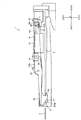
- FIG. 1 is a plan view of a card reader 1 according to an embodiment of the present invention.
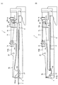
- FIG. 2 is a view for explaining a schematic configuration of the card reader 1 shown in FIG. 1 from the side.
- the card reader 1 is a device that allows a user to manually operate the card 2 to reproduce information recorded on the card 2 and record information on the card 2.
- the card reader 1 includes a magnetic head 3 and an IC contact 4 for reproducing information recorded on the card 2 and recording information on the card 2.
- a card moving path 6 through which the card 2 inserted from the card insertion slot 5 moves is formed linearly.
- the card reader 1 is provided with a lever member 9 as an extraction preventing member for preventing the card 2 inserted therein from being extracted.
- the lever member 9 is configured to be rotatable to a closed position (see FIG. 3B) for closing the card moving path 6 and an open position (see FIG. 3A) for opening the card moving path 6. In the closed position, the inserted card 2 is prevented from being pulled out.
- the card reader 1 includes a torsion coil spring 10 as a biasing member that biases the lever member 9 toward the closed position, a regulation pin 11 as a rotation regulating member that regulates the rotation of the lever member 9 at the closed position, The restricting pin 11 is moved to a rotation restricting position (see FIG. 3B) that restricts the rotation of the lever member 9 and a rotatable position that allows the lever member 9 to rotate (see FIG. 3A). And a solenoid 12 to be operated.
- the card reader 1 includes a first sensor 14 and a second sensor 15 for detecting the presence / absence of the card 2 and a third sensor 16 for detecting that the restriction pin 11 is in the rotation restriction position.
- the first sensor 14, the second sensor 15, and the third sensor 16 of this embodiment are optical sensors that include a light emitting element (not shown) and a light receiving element (not shown) that are arranged to face each other.
- the first sensor 14, the second sensor 15, and the third sensor 16 are all fixed to the frame of the card reader 1.
- the state in which the light from the light emitting elements of the sensors 14 to 16 toward the light receiving element is blocked is referred to as the ON state of the sensors 14 to 16, and the light receiving elements of the sensors 14 to 16 transmit the light from the light emitting elements.
- the state in which light is received is the off state of the sensors 14-16.
- the card 2 moves in the X direction shown in FIGS. That is, the X direction is the moving direction of the card 2.
- the Z direction is the thickness direction of the card 2
- the Y direction is the width direction (short) of the card 2 orthogonal to the X direction that is the moving direction of the card 2 and the Z direction that is the thickness direction of the card 2. Width direction).
- the X1 direction side in FIGS. 1 and 2 is “front (front)”
- the X2 direction side is “back (back)”
- the Y1 direction side is “right”
- the Y2 direction side is “left”.
- the Z1 direction side is “upper” and the Z2 direction side is “lower”.
- the clockwise direction in FIG. 2 is “clockwise”
- the counterclockwise direction in FIG. 2 is “counterclockwise”.
- Card 2 is, for example, a rectangular vinyl chloride card having a thickness of about 0.7 to 0.8 mm.
- a magnetic stripe 2a (see FIG. 1) on which magnetic information is recorded is formed on the surface of the card 2. That is, the card 2 of this embodiment is a magnetic card.
- An IC chip (not shown) is fixed on the surface of the card 2. That is, the card 2 of this embodiment is also a contact type IC card.
- the IC chip may be fixed to the card 2 without forming the magnetic stripe 2a.
- a communication antenna may be built in the card 2, or a printing unit that performs printing by a thermal method may be formed on the surface of the card 2.
- the card 2 may be a PET (polyethylene terephthalate) card having a thickness of about 0.18 to 0.36 mm, a paper card having a predetermined thickness, or the like.
- a part on the front end side of the card reader 1 is a cutout portion 18 cut out so that the user can insert the card 2 and pull out the card 2.
- the notch 18 having a substantially rectangular shape when viewed from the top and bottom is cut away from the front end of the frame of the card reader 1 toward the back side. Is formed.
- a notch 18 is formed at an intermediate position of the frame of the card reader 1, and a right protrusion 19 and a left protrusion 20 are formed on both sides of the notch 18 in the left-right direction.
- a part of the card 2 inserted on the back side of the card reader 1 is exposed at the notch 18.
- the front end of the card moving path 6 is a card insertion slot 5. That is, the card insertion slot 5 is formed at the front end of the right protrusion 19 and the front end of the left protrusion 20. Further, the magnetic head 3 is disposed in the vicinity of the card insertion slot 5. Specifically, the magnetic head 3 is disposed on the front end side of the right protruding portion 19.
- the IC contact 4 is arranged on the back end side of the card reader 1.
- the IC contact 4 is disposed on the upper side of the card moving path 6.
- the IC contact 4 is fixed to the contact holding member 22.
- Part of the contact holding member 22 is engaged with a guide groove (not shown), and the contact holding member 22 moves up and down while being guided by the guide groove and sliding in the front-rear direction. Specifically, the contact holding member 22 descends when it moves to the back side and rises when it moves to the near side. Further, the contact holding member 22 is biased to the near side by a tension coil spring 23.
- the contact holding member 22 may be connected to a predetermined link mechanism, and the link holding mechanism 22 may be configured to move up and down while sliding in the front-rear direction.
- contact holding is performed so that the IC contact 4 comes into contact with the IC chip of the card 2 when the tip of the card 2 inserted into the back side of the card reader 1 is engaged with the card engaging portion of the contact holding member 22.
- the member 22 descends while sliding to the back side. Further, when the card 2 inserted in the back side is pulled to the near side, the contact holding member 22 slides to the near side by the biasing force of the tension coil spring 23 so that the IC contact 4 is separated from the surface of the card 2. To rise.
- the contact holding member 22 is formed with a detection protrusion 22a for detecting the presence or absence of the card 2 on the far end side in cooperation with the second sensor 15.
- the contact holding member 22 slides back and the IC contact 4 comes into contact with the IC chip of the card 2, the second sensor 15 emits light.
- the contact projection 22a is on the near side by the biasing force of the tension coil spring 23 so that the detection projection 22a blocks light traveling from the element to the light receiving element, the light receiving element of the second sensor 15 is separated from the light emitting element.
- the detection protrusion 22a and the second sensor 15 are arranged so as to receive light. That is, in this embodiment, when the detection projection 22a blocks the light traveling from the light emitting element to the light receiving element of the second sensor 15 and the second sensor 15 is turned on, the card 2 is on the far end side of the card reader 1. It is detected.
- FIG. 3A is a view for explaining the state when the card 2 is inserted into the card reader 1 shown in FIG. 1 from the side
- FIG. 3B is the card reader 1 shown in FIG. It is a figure for demonstrating the state which insertion of the card
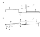
- 4A is a plan view of the lever member 9 shown in FIG. 1
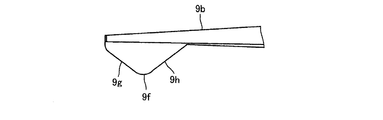
- FIG. 4B is a side view of the lever member 9 shown in FIG.
- the lever member 9 functions to prevent the card 2 inserted inside from being pulled out as described above. Specifically, the lever member 9 functions to prevent the card 2 from being pulled out when the IC chip of the card 2 and the IC contact 4 are in contact with each other to exchange information.
- the lever member 9 is made of resin, for example. Further, the lever member 9 is formed in an elongated rod shape as a whole, and is disposed on the right end side of the card reader 1 with the front-rear direction as a longitudinal direction as shown in FIG.
- the lever member 9 is in contact with the rotation center portion 9 a serving as the rotation center of the lever member 9 and the rear end (front end) of the card 2 to prevent the card 2 from being pulled out.
- the contact part 9b and the regulation pin contact part 9c as a regulation member contact part with which the regulation pin 11 contacts are provided.
- the lever member 9 includes a card detection unit 9d that detects the presence or absence of the card 2 on the front end side in cooperation with the first sensor 14. In this embodiment, insertion of the card 2 into the card reader 1 is also detected by the first sensor 14 and the card detection unit 9d.
- the first sensor 14 is a sensor for detecting insertion of the card 2
- the card detection unit 9 d detects insertion of the card 2 into the card reader 1 in cooperation with the first sensor 14. Part.
- the card contact portion 9b is disposed on the front end side, and the regulation pin contact portion 9c is disposed on the back end side.
- the rotation center part 9a is arrange
- the card detection unit 9d is formed so as to protrude to the right end side.
- the rotation center portion 9a is disposed above the card moving path 6.
- a fixed shaft 25 that rotatably supports the lever member 9 is inserted through the rotation center portion 9a. That is, as shown in FIG. 4B, a shaft hole 9e through which the fixed shaft 25 is inserted is formed in the rotation center portion 9a.
- a protruding portion 9f protruding downward is formed at the front end of the card contact portion 9b.
- the front side surface of the projecting portion 9f is a flat inclined surface 9g that gently slopes downward as it goes to the back side.
- the rear side surface of the protruding portion 9f is a planar orthogonal surface that is substantially orthogonal to the transport direction (X direction) of the card 2.
- the rear side surface of the protruding portion 9f is the rear end of the card 2 to be pulled out. It is the contact surface 9h which contacts.
- the restriction pin contact portion 9 c is disposed above the card moving path 6.
- a flat contact surface 9j with which the regulation pin 11 abuts is formed on the lower surface of the rear end of the regulation pin contact portion 9c.
- the abutting surface 9j is an inclined surface that gently inclines upward as it goes to the back side.
- the fixed shaft 25 inserted into the shaft hole 9e is fixed to the frame of the card reader 1 with the left-right direction as the axial direction.
- the fixed shaft 25 is inserted through the torsion coil spring 10.
- the torsion coil spring 10 is disposed on the left side of the rotation center portion 9a.
- One end of the torsion coil spring 10 is engaged with a spring engaging portion 26 formed on the frame of the card reader 1, and the other end of the torsion coil spring 10 is engaged with an engaging protrusion 9 k formed on the lever member 9. Yes.
- the spring engagement portion 26 is disposed on the front side of the fixed shaft 25, the engagement protrusion 9f is disposed on the rear side of the fixed shaft 25, and the torsion coil spring 10 biases the lever member 9 counterclockwise. is doing. Therefore, when the card 2 is not inserted, as shown in FIG. 2, the lower end of the protruding portion 9 f is in contact with the concave portion 27 formed on the lower surface on the front end side of the card moving path 6. That is, when the card 2 is not inserted, the lever member 9 closes the front end side of the card moving path 6. The position of the lever member 9 when the front end side of the card moving path 6 is closed is the closed position.
- the front end of the card 2 comes into contact with the inclined surface 9g of the lever member 9 that closes the front end side of the card moving path 6.
- the lever member 9 rotates clockwise against the urging force of the torsion coil spring 10, as shown in FIG. It moves to open the front end side of the card moving path 6.
- the position of the lever member 9 when the front end side of the card moving path 6 is opened is the open position.
- the lever member 9 is urged by the urging force of the torsion coil spring 10 as shown in FIG.
- the card is rotated counterclockwise until the lower end of the protrusion 9f comes into contact with the recess 27, and the front end side of the card moving path 6 is closed.
- the card detection part 9d is formed so as to protrude leftward from the back side of the rotation center part 9a. As shown in FIGS. 2 and 3B, when the lever member 9 is in the closed position, the card detector 9d blocks the light from the light emitting element to the light receiving element of the first sensor 14, and FIG. As shown in FIG. 3A, when the lever member 9 is in the open position, the card detector 9d and the first sensor 14 so that the light receiving element of the first sensor 14 receives light from the light emitting element. Is arranged. That is, in this embodiment, when the light receiving element of the first sensor 14 receives light from the light emitting element and the first sensor 14 is turned off, it is detected that the card 2 is on the front end side of the card reader 1.
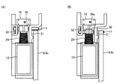
- FIG. 5A is a plan view showing a state when the restriction pin 11 shown in FIG. 1 is in a rotatable position
- FIG. 5B is a view showing the restriction pin 11 shown in FIG. It is a top view which shows a state when there exists in.
- the regulation pin 11 is formed in an elongated cylindrical shape, and is fixed to the distal end side of the plunger 12a of the solenoid 12. Specifically, the restriction pin 11 is fixed to the distal end side of the plunger 12a so that the left and right ends protrude from the plunger 12a with the left and right direction as the axial direction. Further, as shown in FIG. 2, the regulation pin 11 is disposed at substantially the same height as the fixed shaft 25.
- the solenoid 12 is arranged so that the plunger 12a moves in the front-rear direction. Specifically, the solenoid 12 is arranged so that the plunger 12a protrudes toward the back side. The solenoid 12 is arranged so that the plunger 12a is adjacent to the left side of the restriction pin contact portion 9c of the lever member 9. As shown in FIG. 5, the plunger 12 a is inserted into the return compression coil spring 29 and is urged by the compression coil spring 29 in the back direction (that is, the protruding direction of the plunger 12 a). 1 to 3, the illustration of the compression coil spring 29 is omitted.
- the solenoid 12 is not driven (no current is passed through the solenoid 12), and the plunger 12a is moved backward by the urging force of the compression coil spring 29.
- the restricting pin 11 When protruding, the restricting pin 11 is disposed at a position where it cannot contact the contact surface 9j of the restricting pin contact portion 9c (back side position).
- the position of the regulation pin 11 when it cannot contact the contact surface 9j is a rotatable position where the lever member 9 can be rotated.
- the regulation pin 11 Is disposed at a position (a position on the near side) that can contact the contact surface 9j of the restriction pin contact portion 9c.
- the right end portion of the regulation pin 11 is disposed at a position where it can come into contact with the contact surface 9j.
- the position of the restriction pin 11 when it can come into contact with the contact surface 9j is a rotation restriction position for restricting the rotation of the lever member 9.
- a support member 31 formed on the frame of the card reader 1 is disposed between the fixed portion of the restriction pin 11 at the plunger 12a and the right end portion of the restriction pin 11, and the right end side of the restriction pin 11 is It is supported by the support member 31.
- a support member 32 formed on the frame of the card reader 1 is disposed on the left end side of the restriction pin 11, and the left end side of the restriction pin 11 is supported by the support member 32. In FIGS. 2 and 3, the support members 31 and 32 are not shown.
- the support member 31 is formed with a guide groove (guide hole) 31a for guiding the regulation pin 11 in the front-rear direction.
- a guide groove 31 a is formed in the support member 31 so that the shape when viewed from the left-right direction is a rectangular shape whose longitudinal direction is the front-rear direction.
- the height (width in the vertical direction) of the guide groove 31 a is slightly larger than the diameter of the regulation pin 11.
- the support member 31 supports the restriction pin 11 from below. That is, the restriction pin 11 is in contact with the support member 31 in the direction in which the contact surface 9j of the restriction pin contact portion 9c is directed to the restriction pin 11 (clockwise, the rotation direction of the lever member 9 toward the open position)
- the support member 31 supports the regulation pin 11 that comes into contact with the support member 31.
- a guide groove (not shown) for guiding the regulation pin 11 in the front-rear direction is also formed in the support member 32.
- This guide groove is formed in the same manner as the guide groove 31 a formed in the support member 31.
- the support member 32 also supports the restriction pin 11 from the lower side.
- a detection member 30 for detecting the position of the regulation pin 11 in cooperation with the third sensor 16 is fixed to the tip of the plunger 12a.
- the detection member 30 is formed with a detection plate portion 30a that is parallel to the ZX plane formed from the Z direction and the X direction and extends to the upper side and the rear side.
- the solenoid 12 is driven and the plunger 12a is moved so that the detection plate 30a blocks light from the light emitting element to the light receiving element of the third sensor 16.
- the detection plate 30a and the third sensor 16 are arranged so that the light receiving element of the third sensor 16 receives light from the light emitting element when pulled toward the front side. That is, when the light receiving element of the third sensor 16 receives light from the light emitting element and the third sensor 16 is turned off, it is detected that the restriction pin 11 is in the rotation restriction position.
- the lever member 9 when the card 2 is inserted, the lever member 9 is rotated clockwise against the biasing force of the torsion coil spring 10 by the inserted card 2 to move the card.
- the front end side of the road 6 is opened.
- the card detector 9d is detached from between the light emitting element and the light receiving element of the first sensor 14, and the light receiving element receives light from the light emitting element of the first sensor 14, The first sensor 14 is turned off, and insertion of the card 2 is detected.
- the contact holding member 22 is lowered while sliding to the back side by the inserted card 2, and the IC contact 4 contacts the IC chip of the card 2. In this state, information is exchanged between the IC chip of the card 2 and the IC contact 4. Further, when the contact holding member 22 slides to the back side, the detection sensor 22a blocks the light from the light emitting element to the light receiving element of the second sensor 15, so that the second sensor 15 is turned on and the card 2 is in the back. It is detected that it is at the end.
- the magnetic stripe 2a When the recorded magnetic information is reproduced, the magnetic information is reproduced when the card 2 is inserted or pulled out. Further, the frictional force between the card 2 and the IC contact 4 when the IC contact 4 is in contact with the IC chip of the card 2 is slightly larger than the urging force of the tension coil spring 23. Therefore, even if the lever member 9 is in a rotatable state, the card 2 does not pop out to the near side.
- the card moving path 6 is closed by the lever member 9 using the biasing force of the torsion coil spring 10, and the rotation of the lever member 9 that closes the card moving path 6 is restricted by the restriction pin. 11 and the restriction pin 11 is moved by the solenoid 12. Therefore, it is not necessary to rotate the lever member 9 with the power of the solenoid 12, and it is not necessary to maintain the state in which the lever member 9 closes the card moving path 6 with the power of the solenoid 12. Therefore, in this embodiment, even if the solenoid 12 having a small output is used, the card 2 can be prevented from being pulled out, and it is not necessary to flow a large amount of current through the solenoid 12 during operation. As a result, in this embodiment, power saving can be achieved. In addition, since power saving can be achieved, it is possible to employ so-called bus power that operates various devices in the card reader 1 using power supplied from a cable such as a USB.
- the restriction pin 11 is in contact with the support members 31 and 32 in the direction in which the contact surface 9j of the restriction pin contact portion 9c faces the restriction pin 11, and the support members 31 and 32 are provided with the restriction pin 11 that is in contact. Support from below. Therefore, even when a large force acts on the lever member 9 and the restriction pin 11 when the user tries to pull out the card 2 when the lever member 9 whose rotation is restricted is in the closed position, this force is further increased. It is possible to prevent transmission to the solenoid 12. Therefore, damage to the solenoid 12 can be prevented.
- the lever member 9 is rotatable with the left-right direction as the axial direction. Therefore, even when the lever member 9 is biased to the closed position by the torsion coil spring 10, the lever member 9 can be easily rotated to the open position by the inserted card 2. In particular, in this embodiment, since the front end surface of the card contact portion 9b is an inclined surface 9g, the lever member 9 can be easily rotated to the open position by the inserted card 2.
- a guide groove 31 a that guides the restriction pin 11 in the front-rear direction is formed in the support member 31, and a guide groove that guides the restriction pin 11 in the front-rear direction is formed in the support member 32.
- the solenoid 12 is arrange
- the lever member 9 includes a card detection unit 9d that detects the insertion of the card 2 in cooperation with the first sensor 1. That is, the lever member 9 has a part of the insertion detection function of the card 2. Therefore, it is not necessary to separately provide a member for detecting insertion of the card 2 in cooperation with the first sensor 14. Therefore, the configuration of the card reader 1 can be simplified.
- the lever member 9 is formed in the shape of an elongated bar in which the card contact portion 9b, the rotation center portion 9a, and the restriction pin contact portion 9c are arranged in this order in the front-rear direction. Therefore, even when the restriction pin 11 is in contact with the contact surface 9j of the restriction pin contact portion 9c and the rotation of the lever member 9 is restricted, the rotation center portion 9a and the card contact portion 9b And the card 2 can be pulled out. Therefore, even when the user tries to pull out the card 2 when the rotation of the lever member 9 is restricted, it is possible to prevent the lever member 9 and the restriction pin 11 from being excessively stressed. Thus, damage to the lever member 9 and the regulation pin 11 can be prevented.
- the contact surface 9h with which the rear end of the card 2 to be pulled out contacts is a planar orthogonal surface that is substantially orthogonal to the X direction.
- the contact surface 9h with which the rear end of the card 2 to be pulled out contacts is a flat inclined surface that gently slopes downward toward the front side. May be.
- the lever member 9 is biased to the closed position by the torsion coil spring 10.
- the lever member 9 may be biased to the closed position by another spring member such as a compression coil spring, a tension coil spring, or a leaf spring.
- the card reader 1 when the solenoid 12 is driven, the plunger 12a is pulled toward the front side, and the restriction pin 11 is disposed at a position where it can come into contact with the contact surface 9j of the restriction pin contact portion 9c.
- the card reader 1 when the solenoid 12 is driven, the card reader 1 is configured such that when the solenoid 12 is driven, the plunger 12a is pulled to the rear side, and the restriction pin 11 is disposed at a position where the plunger 12a can contact the contact surface 9j. Also good.
- the card reader 1 may be configured such that when the solenoid 12 is driven, the plunger 12a moves in the left-right direction, and the restriction pin 11 is disposed at a position where the plunger 12a can contact the contact surface 9j.
- the regulation pin 11 is arranged on the back end side, and the rotation of the lever member 9 is regulated on the back end side.
- the restriction pin 11 may be disposed on the front end side, and the rotation of the lever member 9 may be restricted on the front end side.
- the regulation pin contact portion 9c may not be formed on the lever member 9.
- the lever member 9 formed with the longitudinal direction as the longitudinal direction rotates with the lateral direction as the axial direction.
- a lever member formed with the left-right direction as the longitudinal direction may rotate with the front-rear direction as the axial direction.
- the first sensor 14 is an optical sensor, but the first sensor 14 may be a mechanical sensor such as a microswitch.
- the card reader 1 includes the magnetic head 3 and the IC contact 4, but the card reader 1 may include only one of the magnetic head 3 or the IC contact 4.
- the IC chip may not be fixed to the card 2.
- the card reader 1 is a manual type, but the configuration of the present invention can also be applied to a card reader having an automatic transport mechanism for the card 2.
Landscapes
- Physics & Mathematics (AREA)
- General Physics & Mathematics (AREA)
- Engineering & Computer Science (AREA)
- Theoretical Computer Science (AREA)
- Conveying Record Carriers (AREA)
Abstract
Description
2 カード
6 カード移動路
9 レバー部材(引抜き防止部材)
9a 回動中心部
9b カード当接部
9c 規制ピン当接部(規制部材当接部)
9d カード検出部(挿入検出部)
10 ネジリコイルバネ(付勢部材)
11 規制ピン(回動規制部材)
12 ソレノイド
12a プランジャ
14 第1センサ(センサ)
31、32 支持部材
31a ガイド溝
X カードの移動方向
Y カードの幅方向
Z カードの厚さ方向
図1は、本発明の実施の形態にかかるカードリーダ1の平面図である。図2は、図1に示すカードリーダ1の概略構成を側面から説明するための図である。
図3(A)は、図1に示すカードリーダ1へカード2を挿入しているときの状態を側面から説明するための図であり、図3(B)は、図1に示すカードリーダ1へのカード2の挿入が完了した状態を側面から説明するための図である。図4(A)は、図1に示すレバー部材9の平面図であり、図4(B)は、図1に示すレバー部材9の側面図である。
この当接面9jは、奥側に向かうにしたがって上方向へ緩やかに傾斜する傾斜面となっている。
図5(A)は、図1に示す規制ピン11が回動可能位置にあるときの状態を示す平面図であり、図5(B)は、図1に示す規制ピン11が回動規制位置にあるときの状態を示す平面図である。
このガイド溝31aの高さ(上下方向の幅)は、規制ピン11の径よりもわずかに大きくなっている。
以上のように構成されたカードリーダ1では、図2に示すように、カード2が挿入されていないときには、ネジリコイルバネ10の付勢力で、レバー部材9はカード移動路6の手前端側を閉鎖している。この状態では、圧縮コイルバネ29の付勢力でプランジャ12aが奥側に突出しており、レバー部材9は回動可能となっている。また、この状態では、接点保持部材22は、引張りコイルバネ23によって手前側に付勢されており、IC接点4は、カード移動路6の上方に配置されている。なお、この状態では、第1センサ14および第3センサ16はオン状態となっており、第2センサ15はオフ状態となっている。
なお、プランジャ12aが手前側に引かれると、第3センサ16はオフ状態となる。
以上説明したように、本形態では、ネジリコイルバネ10の付勢力を利用してレバー部材9でカード移動路6を閉鎖し、カード移動路6を閉鎖しているレバー部材9の回動を規制ピン11で規制するとともに、ソレノイド12で規制ピン11を移動させている。そのため、ソレノイド12の動力でレバー部材9を回動させる必要がなく、また、ソレノイド12の動力でレバー部材9がカード移動路6を閉鎖した状態を維持する必要がない。したがって、本形態では、出力の小さなソレノイド12を使用してもカード2の引抜きを防止することができ、動作時のソレノイド12に多くの電流を流す必要がなくなる。その結果、本形態では、省電力化を図ることができる。また、省電力化を図ることができるため、USB等のケーブルから供給された電力を使用し、カードリーダ1内の各種機器を動作させるいわゆるバスパワーを採用することが可能になる。
そのため、回動規制位置および回動可能位置へ規制ピン11を円滑に移動させることができる。
上述した形態は、本発明の好適な形態の一例ではあるが、これに限定されるものではなく本発明の要旨を変更しない範囲において種々変形実施が可能である。
Claims (6)
- カードが移動するカード移動路と、前記カード移動路を閉鎖する閉位置および前記カード移動路を開放する開位置へ回動可能に構成され挿入された前記カードの引抜きを前記閉位置で防止する引抜き防止部材と、前記閉位置へ前記引抜き防止部材を付勢する付勢部材と、前記閉位置で前記引抜き防止部材に当接して前記引抜き防止部材の回動を規制する回動規制部材と、前記引抜き防止部材の回動を規制する回動規制位置および前記引抜き防止部材の回動を可能とする回動可能位置へ前記回動規制部材を移動させるソレノイドとを備えることを特徴とするカードリーダ。
- 前記開位置へ向かう前記引抜き防止部材の回動方向で前記回動規制部材が当接するとともに前記回動規制部材を支持する支持部材を備えることを特徴とする請求項1記載のカードリーダ。
- 前記引抜き防止部材は、前記カードの移動方向と前記カードの厚さ方向とに略直交する前記カードの幅方向を軸方向として回動可能に構成されていることを特徴とする請求項1または2記載のカードリーダ。
- 前記カードの移動方向へ前記回動規制部材を案内するガイド溝を備え、
前記ソレノイドは、前記ソレノイドを構成するとともに前記回動規制部材が固定されるプランジャが前記カードの移動方向へ移動するように配置されていることを特徴とする請求項3記載のカードリーダ。 - 前記引抜き防止部材は、前記引抜き防止部材の回動中心となる回動中心部と、前記カードの端面に当接して前記カードの引抜きを阻止するカード当接部と、前記回動規制部材が当接する規制部材当接部とを備え、
前記カード当接部と前記回動中心部と前記規制部材当接部とが、前記カードの移動方向にこの順番で配置されていることを特徴とする請求項3または4記載のカードリーダ。 - 前記カードの挿入を検出するためのセンサを備えるとともに、
前記引抜き防止部材は、前記センサと協働して前記カードの挿入を検出する挿入検出部を備えることを特徴とする請求項1から5いずれかに記載のカードリーダ。
Priority Applications (4)
| Application Number | Priority Date | Filing Date | Title |
|---|---|---|---|
| CN200980129211.2A CN102105889B (zh) | 2008-07-22 | 2009-07-15 | 读卡机 |
| US12/675,493 US8657202B2 (en) | 2008-07-22 | 2009-07-15 | Card reader |
| BRPI0904807-3A BRPI0904807A2 (pt) | 2008-07-22 | 2009-07-15 | Leitor de cartão |
| GB1100572.5A GB2474387B (en) | 2008-07-22 | 2009-07-15 | Card reader |
Applications Claiming Priority (2)
| Application Number | Priority Date | Filing Date | Title |
|---|---|---|---|
| JP2008-188053 | 2008-07-22 | ||
| JP2008188053A JP5127616B2 (ja) | 2008-07-22 | 2008-07-22 | カードリーダ |
Publications (1)
| Publication Number | Publication Date |
|---|---|
| WO2010010671A1 true WO2010010671A1 (ja) | 2010-01-28 |
Family
ID=41570144
Family Applications (1)
| Application Number | Title | Priority Date | Filing Date |
|---|---|---|---|
| PCT/JP2009/003325 Ceased WO2010010671A1 (ja) | 2008-07-22 | 2009-07-15 | カードリーダ |
Country Status (6)
| Country | Link |
|---|---|
| US (1) | US8657202B2 (ja) |
| JP (1) | JP5127616B2 (ja) |
| CN (1) | CN102105889B (ja) |
| BR (1) | BRPI0904807A2 (ja) |
| GB (1) | GB2474387B (ja) |
| WO (1) | WO2010010671A1 (ja) |
Families Citing this family (7)
| Publication number | Priority date | Publication date | Assignee | Title |
|---|---|---|---|---|
| JP6357406B2 (ja) | 2014-10-30 | 2018-07-11 | 日本電産サンキョー株式会社 | カードリーダ |
| US10282570B2 (en) | 2014-12-02 | 2019-05-07 | Hirschmann Car Communication Gmbh | Standard card reader for mobile application |
| JP2016122376A (ja) * | 2014-12-25 | 2016-07-07 | 日本電産サンキョー株式会社 | カードリーダ |
| JP6374340B2 (ja) | 2015-03-31 | 2018-08-15 | 日本電産サンキョー株式会社 | カードリーダおよびカードリーダの制御方法 |
| JP6571554B2 (ja) * | 2016-02-16 | 2019-09-04 | 日本電産サンキョー株式会社 | カードリーダ |
| JP2019101623A (ja) * | 2017-11-30 | 2019-06-24 | 日本電産サンキョー株式会社 | カードリーダ |
| JP2023125923A (ja) | 2022-02-28 | 2023-09-07 | ニデックインスツルメンツ株式会社 | カードリーダ |
Citations (4)
| Publication number | Priority date | Publication date | Assignee | Title |
|---|---|---|---|---|
| JPH0338790A (ja) * | 1989-07-05 | 1991-02-19 | Nhk Spring Co Ltd | カードリーダライタ |
| JPH0564963U (ja) * | 1992-01-31 | 1993-08-27 | ティーディーケイ株式会社 | カードの保持機構 |
| JP2001014429A (ja) * | 1999-06-28 | 2001-01-19 | Tamura Electric Works Ltd | カード処理装置 |
| JP2005135160A (ja) * | 2003-10-30 | 2005-05-26 | Saxa Inc | カード処理装置 |
Family Cites Families (4)
| Publication number | Priority date | Publication date | Assignee | Title |
|---|---|---|---|---|
| US3946204A (en) * | 1973-07-13 | 1976-03-23 | Canon Kabushiki Kaisha | Card reader protecting device |
| ATE182999T1 (de) * | 1988-10-14 | 1999-08-15 | Omron Tateisi Electronics Co | Kartenlesegerät mit verriegelung |
| JP3490285B2 (ja) | 1998-03-11 | 2004-01-26 | 株式会社三協精機製作所 | カードリーダ |
| US6736318B2 (en) * | 2000-07-07 | 2004-05-18 | Amphenol-Tuchel Electronics Gmbh | Smart-card reader including mechanical locking means |
-
2008
- 2008-07-22 JP JP2008188053A patent/JP5127616B2/ja active Active
-
2009
- 2009-07-15 CN CN200980129211.2A patent/CN102105889B/zh not_active Expired - Fee Related
- 2009-07-15 GB GB1100572.5A patent/GB2474387B/en not_active Expired - Fee Related
- 2009-07-15 US US12/675,493 patent/US8657202B2/en active Active
- 2009-07-15 WO PCT/JP2009/003325 patent/WO2010010671A1/ja not_active Ceased
- 2009-07-15 BR BRPI0904807-3A patent/BRPI0904807A2/pt not_active Application Discontinuation
Patent Citations (4)
| Publication number | Priority date | Publication date | Assignee | Title |
|---|---|---|---|---|
| JPH0338790A (ja) * | 1989-07-05 | 1991-02-19 | Nhk Spring Co Ltd | カードリーダライタ |
| JPH0564963U (ja) * | 1992-01-31 | 1993-08-27 | ティーディーケイ株式会社 | カードの保持機構 |
| JP2001014429A (ja) * | 1999-06-28 | 2001-01-19 | Tamura Electric Works Ltd | カード処理装置 |
| JP2005135160A (ja) * | 2003-10-30 | 2005-05-26 | Saxa Inc | カード処理装置 |
Also Published As
| Publication number | Publication date |
|---|---|
| BRPI0904807A2 (pt) | 2015-06-30 |
| US8657202B2 (en) | 2014-02-25 |
| US20110121078A1 (en) | 2011-05-26 |
| CN102105889A (zh) | 2011-06-22 |
| JP2010026826A (ja) | 2010-02-04 |
| GB201100572D0 (en) | 2011-03-02 |
| GB2474387B (en) | 2012-12-19 |
| JP5127616B2 (ja) | 2013-01-23 |
| CN102105889B (zh) | 2014-04-23 |
| GB2474387A (en) | 2011-04-13 |
Similar Documents
| Publication | Publication Date | Title |
|---|---|---|
| JP5127616B2 (ja) | カードリーダ | |
| JP7154038B2 (ja) | カードリーダ | |
| JP5179924B2 (ja) | カードリーダのシャッター機構およびカードリーダ | |
| JP5172628B2 (ja) | カード発行機 | |
| JP6571554B2 (ja) | カードリーダ | |
| JP5919171B2 (ja) | 手動式カードリーダ | |
| JP6053387B2 (ja) | カード回収機構およびカード発行装置 | |
| US7556195B2 (en) | Card reader and writer | |
| JP4275514B2 (ja) | カードリーダ | |
| US9922213B2 (en) | Card reader | |
| JP2016122376A (ja) | カードリーダ | |
| JP2014035682A (ja) | カード回収庫 | |
| CN105580030A (zh) | 读卡器 | |
| JP6873899B2 (ja) | カードリーダ | |
| JP2008165483A (ja) | カード回収機構およびカード発行装置 | |
| JP6374340B2 (ja) | カードリーダおよびカードリーダの制御方法 | |
| JP6143603B2 (ja) | カード処理装置 | |
| JP2023125923A (ja) | カードリーダ | |
| TWI227860B (en) | Swipe hybrid card reader | |
| JP4040442B2 (ja) | 手動式カードリーダ | |
| JP2514418B2 (ja) | Icカ―ドリ―ダにおけるシヤツタ機構 | |
| JP2007011458A (ja) | カードリーダ | |
| JP2007172033A (ja) | カードリーダライタ | |
| JP2018116415A (ja) | カードリーダ | |
| JPH0525549U (ja) | 係止確認機構 |
Legal Events
| Date | Code | Title | Description |
|---|---|---|---|
| WWE | Wipo information: entry into national phase |
Ref document number: 200980129211.2 Country of ref document: CN |
|
| WWE | Wipo information: entry into national phase |
Ref document number: 784/DELNP/2010 Country of ref document: IN |
|
| WWE | Wipo information: entry into national phase |
Ref document number: 12675493 Country of ref document: US |
|
| 121 | Ep: the epo has been informed by wipo that ep was designated in this application |
Ref document number: 09800188 Country of ref document: EP Kind code of ref document: A1 |
|
| ENP | Entry into the national phase |
Ref document number: 1100572 Country of ref document: GB Kind code of ref document: A Free format text: PCT FILING DATE = 20090715 |
|
| WWE | Wipo information: entry into national phase |
Ref document number: 1100572.5 Country of ref document: GB |
|
| NENP | Non-entry into the national phase |
Ref country code: DE |
|
| 122 | Ep: pct application non-entry in european phase |
Ref document number: 09800188 Country of ref document: EP Kind code of ref document: A1 |
|
| ENP | Entry into the national phase |
Ref document number: PI0904807 Country of ref document: BR Kind code of ref document: A2 Effective date: 20100309 |