WO2009157345A1 - 細胞操作観察装置 - Google Patents
細胞操作観察装置 Download PDFInfo
- Publication number
- WO2009157345A1 WO2009157345A1 PCT/JP2009/060955 JP2009060955W WO2009157345A1 WO 2009157345 A1 WO2009157345 A1 WO 2009157345A1 JP 2009060955 W JP2009060955 W JP 2009060955W WO 2009157345 A1 WO2009157345 A1 WO 2009157345A1
- Authority
- WO
- WIPO (PCT)
- Prior art keywords
- cell
- observation
- dish
- substance
- cells
- Prior art date
- Legal status (The legal status is an assumption and is not a legal conclusion. Google has not performed a legal analysis and makes no representation as to the accuracy of the status listed.)
- Ceased
Links
Images


Classifications
-
- G—PHYSICS
- G06—COMPUTING OR CALCULATING; COUNTING
- G06T—IMAGE DATA PROCESSING OR GENERATION, IN GENERAL
- G06T1/00—General purpose image data processing
- G06T1/0014—Image feed-back for automatic industrial control, e.g. robot with camera
Definitions
- the present invention relates to a cell manipulation observation apparatus that introduces a substance such as a gene into a cell and observes the cell into which the substance has been introduced.
- Patent Document 1 discloses a method of introducing a substance into a cell by pointing the cell in the monitor with a mouse cursor by relative alignment between the cell and the capillary. Thereby, operation can be performed rapidly. In addition, by installing the incubator with the reference position aligned, it is possible to reproduce the position at the time of rearrangement.
- Patent Document 2 two reference points are provided, and when the incubator is rearranged, the observation position can be accurately reproduced by measuring the position of these two points and converting the coordinates.
- An apparatus for observing cultured cells is disclosed.
- Patent Document 3 discloses a configuration in which the coordinate value of the introduced cell is recorded and two reference points are provided and coordinate transformation is performed so that the position of the introduced cell can be reproduced even if the incubator is rearranged. is doing.
- Patent Documents 1 to 3 there is no means for determining what kind of substance is introduced into which cell, and it has been necessary to rely on the memory of the operator.
- the present invention has been made in view of the above points, and an object of the present invention is to provide a cell manipulation observation apparatus capable of easily discriminating what substance is introduced into which cell.
- a cell manipulation observation apparatus for introducing and observing a substance into a cell
- Observation means for imaging and displaying the cells in the incubator placed on the stage;
- designation means for designating the position of the cell to introduce the substance,
- An introduction position arrangement means for driving the stage and arranging the position designated by the designation means at a predetermined cell operation position in the visual field of the observation means;
- Cell manipulation means for introducing the introduced substance suspended in the culture medium in the incubator into the cells by perforating the cell membrane of the cells moved to the predetermined cell manipulation position by the introduction position arranging means,
- Display means for displaying introduced cell information including cell position information indicating the designated position and introduced substance information indicating the introduced substance;
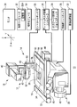
- FIG. 1 is an overall configuration diagram showing a cell manipulation observation apparatus according to a first embodiment of the present invention.
- FIG. 2 is a diagram showing a configuration relating to attachment of the adapter of the chip driving device.
- FIG. 3 is a diagram showing the configuration of the needle.
- FIG. 4 is a diagram for explaining interference due to the angle of the needle.
- FIG. 5 is a diagram for explaining the movable range.
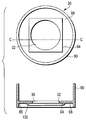
- FIG. 6 shows a top view and a cross-sectional view of a glass base dish.
- FIG. 7 is a diagram for explaining a movable range in the case of a glass base dish.
- FIG. 8 is a flowchart for explaining the flow of the cell manipulation and observation method using the cell manipulation observation apparatus according to the first embodiment.
- FIG. 8 is a flowchart for explaining the flow of the cell manipulation and observation method using the cell manipulation observation apparatus according to the first embodiment.
- FIG. 9A is a diagram showing a first half of a series of flowcharts for explaining a control program for cell manipulation / observation operation by the control computer.
- FIG. 9B is a diagram showing the latter half of a series of flowcharts for explaining a control program for cell manipulation / observation operation by the control computer.
- FIG. 10 is a diagram illustrating an example of an operation window displayed on the monitor.
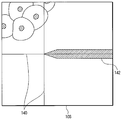
- FIG. 11 is a diagram illustrating a display example of the monitor display unit when the position of the chip unit is specified.
- FIG. 12 is a flowchart of the first mode cell introduction operation and the second mode cell introduction operation.
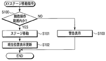
- FIG. 13 is a flowchart of the XY stage movement command operation in the cell manipulation observation apparatus according to the second embodiment of the present invention.
- a cell manipulation observation apparatus 10 As shown in FIG. 1, a cell manipulation observation apparatus 10 according to the first embodiment of the present invention includes an inverted microscope 12 for observing cells and a chip driving device 14 attached to the inverted microscope 12.
- the inverted microscope 12 includes a dish holder 16, an illumination device 18, an observation device 20, a microscope XY stage 22, an XY stage operation joystick 24, a dish holder movement controller 26, a microscope controller 28, and an image processing device. 30 and a control computer 32.
- the dish holder 16 includes a ⁇ table 34 on which a dish 36, which is an incubator for culturing cells, is placed.
- the illumination device 18 illuminates the cells on the dish holder 16.
- the observation device 20 observes the light reflected or transmitted through the cell or the fluorescence generated from the cell.
- the microscope XY stage 22 moves the dish holder 16 in the X direction and the Y direction.
- the XY stage operation joystick 24 is an operation member for an operator to instruct the movement of the microscope XY stage 22.
- the dish holder movement controller 26 drives and controls the microscope XY stage 22 and the ⁇ table 34 in accordance with instructions from the XY stage operating joystick 24.
- the microscope controller 28 controls the illumination device 18 and the observation device 20.
- the image processing device 30 processes the image obtained by the observation device 20.
- the control computer 32 controls the entire inverted microscope 12 through the dish holder movement controller 26 and the microscope controller 28.
- the control computer 32 is connected to a monitor 38 that displays an image processed by the image processing device 30. Therefore, the observation device 20, the image processing device 30, the control computer 32, and the monitor 38 function as observation means that images and displays the cells in the dish holder 16.
- the control computer 32 includes a storage unit 32A for storing various types of information.
- the illumination device 18 includes a transmission illumination light source 40, a condenser lens 42, and an epi-illumination light source 44.
- the transmitted illumination light source 40 irradiates the cells with illumination light from the side opposite to the observation device 20.
- the condenser lens 42 collects the illumination light emitted from the transmitted illumination light source 40 on the cells.
- the epi-illumination light source 44 irradiates the cells with illumination light from the same direction as the observation device 20.
- the observation apparatus 20 includes an observation optical system including an objective lens (not shown), a CCD camera 46, and an eyepiece lens 48.
- the CCD camera 46 captures light from the cells via the observation optical system and acquires an image.
- the eyepiece 48 is used by the operator to directly observe the light from the cells.
- the chip driving device 14 includes an apparatus main body 50, a microscope adapter 52, an operation module 54, and a control box 56.
- the microscope adapter 52 is an attachment part to the condenser lens 42 of the apparatus main body 50.
- the operation module 54 can be installed at an arbitrary position.
- the control box 56 controls the apparatus main body 50 according to the operator's operation of the operation module 54.
- the control box 56 is connected to the control computer 32 via the dish holder movement controller 26, and is configured to be able to control the apparatus main body 50 by the control computer 32.
- FIG. 1 shows a state in which the apparatus main body 50 is attached to the right side of the condenser lens 42 with respect to the front side of the inverted microscope 12 that is the side on which the eyepiece 48 is provided.
- the apparatus main body 50 includes an adapter holding portion 58, a Z driving portion 60, and a needle position adjusting knob (not shown).
- the adapter holding portion 58 is a member for attaching the adapter 62
- the adapter 62 is a member for mounting a needle 64 as a cell manipulation tool including a tip portion 66 to be driven.
- the Z driving part 60 moves the tip part 66 in the Z direction by moving the adapter holding part 58 in the Z direction.
- the needle position adjustment knob adjusts the XY position of the tip portion 66 by moving the adapter holding portion 58 in the X direction and the Y direction.
- the adapter holding part 58 includes a Z driving part attaching part 68, a mounting member, and a fitting part 70.
- the Z driving unit mounting unit 68 is configured to connect the adapter holding unit 58 to a straight line (not shown) of the Z driving unit 60 via an XY driving mechanism (not shown) (the control box 56 drives the adapter holding unit 58 by this driving mechanism). Used to attach to moving mechanism.
- the mounting member is for detachably mounting the adapter 62, and is provided on the opposite side to the Z drive portion mounting portion 68 of the adapter holding portion 58 in the longitudinal direction. This mounting member is constituted by a magnet 72 if the adapter 62 is made of metal or has a metal portion at a corresponding location.
- the right side of the alternate long and short dash line is a portion accommodated in the apparatus main body 50. That is, the magnet 72 is provided at a position outside the apparatus main body 50.
- the fitting portion 70 is disposed in the vicinity of the magnet 72 and is fitted into a hole or groove provided in the adapter 62 for positioning the adapter 62.
- the fitting portion 70 protrudes toward the front side of the inverted microscope 12 so that the adapter 62 can be attached by insertion from the front side.
- the magnet 72 and the fitting portion 70 may be provided on the back side of the adapter holding portion 58 so that the adapter 62 can be attached even when the apparatus main body 50 is attached to the left side of the condenser lens 42.
- the adapter holding portion 58 may be configured to be replaceable according to the mounting position of the apparatus main body 50.
- the needle 64 attached to the adapter 62 includes a cantilever tip 74 and a shaft 76 as shown in FIG.
- the cantilever tip 74 is formed with the tip portion 66.
- the shaft 76 holds the cantilever chip 74 by bonding the cantilever chip 74 to the tip thereof.
- the cantilever chip 74 is manufactured by a silicon process, and includes a silicon base part 78, a flexible lever part 80, and the chip part 66.
- the silicon base portion 78 is another portion, that is, a portion for bonding to the shaft 76.
- the lever portion 80 extends from the silicon base portion 78, and has an elastic constant of about 2 N / m with a thickness of 2.7 ⁇ m and a length of 240 ⁇ m, for example.
- the tip portion 66 is formed at the free end of the lever portion 80 at an angle of approximately 90 degrees with respect to the longitudinal direction of the lever portion 80.
- the needle 64 is inserted and fixed in a hole (not shown) formed in the adapter 62, and then the adapter 62 with the needle 64 attached is attached to the apparatus main body 50. Yes. By doing so, it is possible to replace the needle 64 that is basically a component (consumable) having a high degree of replacement. Therefore, the chip driving device 14 can be used repeatedly without the risk of contamination.
- the elongated needle 64 when the elongated needle 64 is directly attached to the apparatus main body 50, the workability is poor, and the tip portion 66 may hit somewhere on the inverted microscope 12 such as the dish holder 16 during the attachment work and may be damaged.
- the needle 64 since the needle 64 is attached to the adapter 62 removed from the apparatus main body 50 and the adapter 62 is attached from the front side of the apparatus main body 50, the possibility of such damage is reduced. be able to.
- the adapter 62 is configured to hold the shaft 76 of the needle 64 obliquely downward at a predetermined angle when the adapter 62 is attached to the apparatus main body 50, and the cantilever chip 74 is configured to support the shaft 76. Are bonded to each other at a predetermined angle. Further, as described above, the tip portion 66 is provided so as to extend in a direction intersecting the longitudinal direction of the lever portion 80. Therefore, in a state where the adapter 62 is attached to the apparatus main body 50, the tip portion 66 is held at the free end of the lever portion 80 with the tip substantially downward vertically.
- the fixed angle at which the adapter 62 holds the shaft 76 is determined as follows. That is, as shown with reference numeral 82 in FIG. 4, if the shaft 76 is raised too much, the shaft 76 interferes with the condenser lens 42. If the length of the needle 64 is about 50 mm, for example, if the shaft 76 is raised more than 60 degrees, it interferes with the condenser lens 42. On the other hand, if the shaft 76 is overlaid, the shaft 76 interferes with the peripheral wall portion of the dish 36 as indicated by reference numeral 84 in FIG. In general, in a 35 mm glass bottom dish that is frequently used in cell culture, if the shaft 76 is laid more than 30 degrees, it interferes with the peripheral wall portion of the dish 36. Therefore, in this embodiment, the fixed angle at which the adapter 62 holds the shaft 76 is set to 45 degrees, which is an intermediate between 30 degrees and 60 degrees.
- a movable range 86 as shown by a one-dot chain line in FIG. 5 is obtained, and the glass surface (about ⁇ 14 mm) of the 35 mm glass bottom dish is obtained.
- the operation can be performed without the shaft 76 interfering with the condenser lens 42 or the peripheral wall portion of the dish 36.
- the fixed angle at which the adapter 62 holds the shaft 76 is determined so as to give the needle 64 a sufficient movable range 86 in consideration of interference with the condenser lens 42 and the dish 36 used.
- a hole (not shown) for inserting and fixing the needle 64 is formed in the adapter 62 so as to hold the shaft 76 at this fixed angle.
- the glass base dish used as the said dish 36 is formed in the cylindrical shape by the baseplate part 88 which consists of synthetic resin materials, such as a polystyrene, and the surrounding side part 90, as shown in FIG.
- One through hole 92 having a circular shape is formed in the central portion of the bottom plate portion 88.
- a plate-like glass portion 94 that is sufficient to completely cover the opening surface 96 of the through-hole 92 is joined from the lower surface 98 side of the bottom plate portion 88 by an adhesive 100 made of a silicon adhesive or an acrylate adhesive. Yes. Thereby, the entire opening surface 96 of the through-hole 92 is shielded by the plate-like glass portion 94.
- the bottom portion of the dish 36 is constituted by the bottom plate portion 88 and the plate-like glass portion 94.
- the movable range 86 in which the shaft 76 can move the needle 64 without interfering with the bottom plate portion 88 of the dish 36 is the opening surface of the through hole 92. It is limited to a range narrower than 96.
- the movable range 86 varies depending on the diameter of the shaft 76, the length of the cantilever tip 74, and the like.
- the ⁇ table 34 is driven to rotate the dish 36, so that the restriction due to the interference with the bottom plate 88 of the dish 36 can be avoided.
- the observation range that is the range that can be observed with the inverted microscope 12 is the entire opening surface 96 of the through-hole 92 of the dish 36 in which the cells are cultured.
- a cell operation range that is a range in which cells can be operated by the chip driving device 14 is the movable range 86. Therefore, in the cell operation observation device 10 according to the present embodiment, the observation range and the cell operation range are different.
- the operation module 54 of the chip driving device 14 includes a Z value set button, although not particularly illustrated.
- This Z value set button is a button for instructing to store an arbitrary position in the Z direction. Even when the operation of the adapter holding unit 58 in the Z direction by the Z driving unit 60 is performed by the operation module 54, the position stored by the Z value set button is below (the direction of the cells in the dish 36). The adapter holder 58 can be prevented from descending.
- the Z value set button includes a latch mechanism, and when the operator performs a pressing operation, that is, an ON operation, the Z value setting button maintains the pressed state, that is, the ON state until the pressing operation is performed again.
- the Z value set button in the OFF state is referred to as “first mode”
- the ON state is referred to as “second mode”.
- the operator of the cell operation observation device 10 first confirms whether or not the chip driving device 14 for cell operation is ready (step TS1). If the preparation has not been completed, the needle 64 is inserted and attached to the adapter 62 removed from the apparatus main body 50 (step TS2). Then, the adapter 62 to which the needle 64 is attached is attached from the front side of the inverted microscope 12 to the adapter holding portion 58 of the apparatus main body 50 attached to the condenser lens 42 via the microscope adapter 52 (step). ST3).
- chip positioning is performed (step ST4). That is, the operator operates a needle position adjusting knob (not shown) while observing with the eyepiece 48 or the monitor 38, and visually observes the position of the tip portion 66 formed at the tip of the needle 64. Set to the center position of the lens (field center position). This is performed without placing the dish 36 on the dish holder 16.
- step ST5 the operator next places the dish 36 on the dish holder 16. Perform (step ST5).
- the dish 36 is set in a state in which the substance to be introduced is turbid in the culture solution in order to introduce the substance into cells cultured in the culture solution in the dish 36.
- step ST6 the control computer 32 controls each part of the inverted microscope 12 and the chip driving device 14 via the dish holder movement controller 26, the microscope controller 28, and the control box 56 in accordance with the above operation of the operator. This is performed by driving control, and details thereof will be described later.
- the dish 36 is collected (step ST7).
- step ST1 when a substance is introduced into cells cultured in another dish 36, the above operation is repeated.
- the chip driver 14 since the chip driver 14 has already been prepared, the process can proceed from step ST1 to step ST5.
- the needle 64 may be replaced by proceeding to step ST2 instead of proceeding from step ST1 to step ST5.
- the culture solution in which the substance to be introduced is turbid is washed away, and a new culture solution is replenished.
- the cells into which the substance has been introduced are further cultured in the dish 36. And after observing a predetermined period, it observes using the cell operation observation apparatus 10.
- step ST1 the chip driving device 14 is not necessary, and the process proceeds from step ST1 to step ST5. Therefore, the operator places the dish 36 in which the substance-introduced cells to be observed are cultured on the dish holder 16 that is moved in the horizontal direction by the microscope XY stage 22.
- step ST6 the operator operates the XY stage operation joystick 24 and the operation module 54 while confirming the image displayed on the monitor 38 to perform the cell operation / observation operation, so that a desired cell in the dish 36 can be obtained. Observe (step ST6).
- the dish 36 is collected (step ST7).
- step ST6 the cell manipulation / observation operation in step ST6 will be described.
- This cell manipulation / observation operation is performed by executing a control program for performing the operation as shown in FIGS. 9A and 9B in the control computer 32.
- the operation window 102 includes a menu bar 104, a monitor display unit 106, an operation unit 108, and an incubator map display unit 110.
- the monitor display unit 106 is an area for displaying an image acquired by the CCD camera 46 and processed by the image processing device 30.
- the operation unit 108 is an area for performing various operation buttons and a list display.
- the incubator map display unit 110 is an area indicating which portion of the dish 36 placed on the dish holder 16 is displayed by the monitor display unit 106.
- the operation unit 108 includes, as operation buttons, an “introduction” button 112, a “needle setting mode” button 114, an “introduction point registration” button 116, an “operation area registration” button 118, a “coordinate conversion” button 120, and a “reference point”.
- the “introduction” button 112 is a button for instructing introduction of a substance.
- the “needle setting mode” button 114 is a button for instructing the position registration of the tip portion 66.
- the “introduction point registration” button 116 is a button for instructing registration of a position where a substance is introduced.
- the “register operation area” button 118 is a button for instructing registration of an area including a cell into which a substance is introduced.
- the “coordinate conversion” button 120 is a button for instructing registration of the reference point of the dish 36.
- the “reference point clear” button 122 is a button for instructing to clear the registered reference point.
- the “observation” button 124 is a button for instructing to perform observation.
- the operation unit 108 includes an introduced cell list 126.
- the introduced cell list 126 displays the contents of the introduced cell list configured in the storage unit 32A of the control computer 32.
- the introduced cell information of each cell is registered in response to the mouse click operation of the “introduction point registration” button 116.
- the introduced cell information includes position information (XY coordinates) and introduced substance information.
- the introduced substance information includes a display color on the monitor display unit 106, a substance name, a particle size, a concentration, an observation condition, and the like.
- the substance to be introduced may be introduced into either the cell nucleus or the cytoplasm.
- a fluorescent reagent such as a gene, a dye, or a quantum dot, an ion, a peptide, a protein, a polysaccharide, or the like that can be turbid in the dish 36 may be used.
- These substances to be introduced are preferably registered in advance so that they can be selected from the introduction substance list 128 by a pull-down list. By displaying such an introduced cell list 126, the contents of introduction can be grasped for each cell.
- the operation unit 108 includes an operation area list 130.
- the operation area list 130 displays the contents of the operation area list configured in the storage unit 32A of the control computer 32.
- operation area information is registered in response to a mouse click operation of the “register operation area” button 118.
- This operation area information includes position information of an area where a substance is introduced or contains a cell, for example, XY coordinates of a predetermined point such as the upper left of the area. Note that the size of the operation area corresponds to the range displayed on the monitor display unit 106.
- the incubator map display unit 110 displays the observation range 132 and the cell operation range 134 in a distinguishable manner.
- the observation range 132 is a diagram corresponding to the entire range of the open surface 96 of the through-hole 92 of the dish 36 in which cells are cultured and which can be observed with the inverted microscope 12.
- the cell manipulation range 134 is a range in which cell manipulation can be performed by the chip driving device 14 in the observation range 132.
- the incubator map display unit 110 presents the area displayed by the monitor display unit 106, that is, the currently observed position as the current position 136, and each area registered and displayed in the operation area list 130. Is displayed as the cell operation area 138.
- the observation range 132 that is the range of the dish 36 that can be observed
- the cell operation range 134 that is the range in which cells can be operated
- the monitor display unit 106 are currently observed.
- the current position 136 that is the current position is superimposed and displayed. By doing so, the shaft 64 or the microscope XY stage 22 on which the dish 36 is placed can be operated so that the current position does not deviate from the cell operation range 134. It is possible to eliminate the risk of hitting. Also. Since the monitor display unit 106 for displaying the observation image of the current field of view and the incubator map display unit 110 are displayed on the same screen (operation window 102), it is easy to grasp where the present observation is being made. become able to.
- control computer 32 first determines whether or not creation of a new file has been selected from the file menu displayed by the mouse click operation of the “file” item of the menu bar 104 in the operation window 102 (step). S11).
- a sample information input window (not shown) is opened separately to accept input of sample information, and the input sample information is temporarily stored in the storage unit 32A (step S12).
- This sample information includes date, number, cell, and the like.
- the type of the dish 36 and the type of the chip driving device 14 can be selected from a pull-down menu.
- the introduced substance is selected from the pull-down list of the introduced substance list 128 (step S13).
- the introduced substance is selected from the pull-down list of the introduced substance list 128 (step S13).
- By inputting the observation conditions it is possible to eliminate the need to set the observation conditions each time a substance-introduced cell is to be observed later.
- Such information on the introduced substance is also temporarily stored in the storage unit 32A.
- the microscope XY stage 22 is driven by the dish holder movement controller 26 to move the dish holder 16 in the horizontal direction, and the observation range and the cell operation range are set by measuring the outer shape of the dish 36, and these are stored in the storage unit 32A. Is temporarily stored (step S14).
- the observation range can be specified based on the type of the input dish 36 by measuring three points on the outer circumference if the dish 36 is circular and two diagonal points if the dish 36 is square. Note that this measurement can be automatically performed by detecting a boundary from an image acquired by the CCD camera 46 by image processing and image-processed by the image processing device 30, or an operator can perform an XY stage operation joystick. 24 may be operated to designate the above two or three points.
- the dish holder movement controller 26, the control computer 32, the CCD camera 46, the image processing apparatus 30, etc. function as measurement means for measuring the shape of the dish 36 placed on the microscope XY stage 22.
- the observation range can be easily set by measuring the shape of the dish 36.
- the storage unit 32A of the control computer 32 stores in advance a list of cell operation ranges corresponding to combinations of the type of the dish 36 and the type of the chip driving device 14. Therefore, the cell operation range can be read from the storage unit 32A and set in accordance with the type of the dish 36 specified and temporarily stored and the type of the chip driving device 14.
- the set observation range and cell operation range and the current position displayed on the monitor display unit 106 are displayed on the incubator map display unit 110.
- the observation range 132, the cell operation range 134, and the current position 136 are displayed (step S15).
- step S16 registration of the reference position is accepted and temporarily stored in the storage unit 32A (step S16). This is because when the operator moves a cursor (not shown) to a desired position on the monitor display unit 106 and designates the position by a mouse click operation and operates the “coordinate conversion” button 120, the designated position is set according to the button operation. It is registered as a reference position. Two reference positions are registered. The registered reference position is used for position alignment (coordinate conversion and rotation driving by the ⁇ table 34) when the collected dish 36 is set again and observed.
- the Z drive unit 60 of the chip drive device 14 is operated via the control box 56, and the chip unit 66 is brought close to the cell from above the cell (step S17). .
- the operator lowers the tip portion 66 to a position where it can be observed in focus with the cells in the dish 36.
- the position of the chip unit 66 is registered in the storage unit 32A (step S18). This is because, after the operator operates the “needle setting mode” button 114, as shown in FIG. 11, the cursor 140 is moved to the image of the cantilever chip 74 (cantilever chip image 142) displayed on the monitor display unit 106.
- the position of the chip part 66 is designated by performing a mouse click operation in accordance with the tip part, the designated position is registered as the position of the chip part 66 in accordance with the mouse click operation. In this way, the position of the chip portion 66 can be registered. Further, the position can be corrected quickly by performing the same operation again.
- the control computer 32 functions as a setting means for setting a predetermined cell operation position.
- control computer 32 may automatically determine the geometric shape of the cantilever tip image 142 by image processing according to the operation of the “needle setting mode” button 114. Absent. That is, from the geometric shape of the cantilever chip 74, the position of the chip part 66 can be easily determined without allowing the chip part 66 to enter the cell.
- the shaft 76 of the chip driving device 14 is installed with an inclination, it is difficult to accurately detect the position of the chip portion 66.
- the tip portion 66 can be set without trouble by an operator's designation operation or by automatic determination from the geometric shape of the cantilever tip 74.
- step S19 designation of the position where the substance is introduced is accepted (step S19). This is because when the operator selects a cell to be introduced on the monitor display unit 106, the cursor 140 is placed on the position to be introduced in the selected cell, and the mouse is clicked, the control computer 32 responds to the operation. The above position is accepted as the designated position. As described above, the control computer 32 also functions as a designation unit that designates the position of the cell into which the substance is introduced among the cells in the dish holder 16. More specifically, the cell is selected as follows while the operator looks at the image on the monitor display unit 106.
- the dish 36 is moved to a predetermined cell operating position where cell introduction is performed by the chip driving device 14. .
- the operator hits the dish 36 by operating the joystick 24 for operating the XY stage while confirming the display of the cell operation range 134 and the current position 136 on the incubator map display unit 110. Can be prevented.
- the following designation method can also be adopted. That is, first, the operation of moving the dish 36 and registering the cell operation area in the operation area list provided in the storage unit 32A by operating the “Register Operation Area” button 118 as described above is repeated. Thereafter, by selecting a desired cell operation area on the operation area list 130 displaying the contents of the operation area list of the storage unit 32A and specifying it by a mouse double-click operation, the position of the cell operation area is determined as a cell. The operation area 138 is displayed on the monitor display unit 106. Then, a cell to be introduced is selected from the displayed cell operation area 138.
- control computer 32 calculates the relative position between the position of the tip portion 66 and the specified position, drives the microscope XY stage 22 via the dish holder movement controller 26, and the specified position is the tip position of the tip portion 66.
- the dish 36 is moved to a position overlapping the position (step S20).
- the control computer 32 and the dish holder movement controller 26 function as introduction position arrangement means for driving the microscope XY stage 22 and arranging the designated position at the predetermined cell operation position.
- the subsequent operation differs depending on whether or not the Z value is set.
- the first mode cell introduction operation is performed (step S22).
- the tip portion 66 is slightly lowered in the Z direction to determine the optimum position in the Z direction (step S22A). This is because the operator operates the operation module 54 while observing the image on the monitor display unit 106 and confirming “cell distortion” or “deflection of the lever unit 80”, and the control computer 32 performs the operation. In response, the Z driving unit 60 is driven via the control box 56. At this time, the operation module 54 is operated by appropriately switching the sensitivity between large, medium, and small movement amount setting dials (not shown) provided in the operation module 54. Further, instead of operating the operation module 54, as shown in FIG. 10, the operation unit 108 is provided with a “step down” button 144, a “step up” button 146, and a step amount setting unit 148. You may make it instruct
- the tip portion 66 is lowered and brought closer to the bottom surface of the dish 36, and contacts the cells in the dish 36 while the tip of the tip portion 66 is lowered.
- the tip portion 66 is further lowered, if the tip end of the tip portion 66 is inside the cell, that is, the cell membrane and the nucleus position, a hole or a scratch is made in the nucleus.
- the turbid substance in the dish 36 By passing the turbid substance in the dish 36 through the holes or scratches thus formed, the substance flows into the cells.
- the channel coupled to the stretch receptor or the like is opened by physical stimulation by deforming the cells at the tip portion 66.
- Step S22B the control computer 32 stores the position of the adapter holding unit 58 at that time detected by a position detection unit (not shown) in the storage unit 32A as a Z value indicating the optimum position. (Step S22C).
- the tip portion 66 is retracted by raising the needle 64 according to the operation of the operation module 54 (step S22D).
- the cell membrane is recovered by self-repair and a substance is taken into the cell after a certain period of time.
- the chip driving device 14, the control computer 32, the operation module 54, and the control box 56 perforate the cell membrane of the cell moved to the predetermined cell operation position, thereby culturing the culture in the dish holder 16. It functions as a cell manipulation means for introducing the introduced substance turbid in the liquid into the cells.
- the control computer 32 sends the coordinate value (introduction position information) of the microscope XY stage 22 and the introduction substance information corresponding to the position of the chip part 66 to the introduction point No. of the introduction cell list provided in the storage part 32A. 1 is registered (step S22E).
- the registered contents are displayed on the operation unit 108 as the introduced cell list 126. That is, the introduced cell list 126 functions as a display means for displaying introduced cell information including cell position information (introduced position information) indicating the designated position and introduced substance information indicating the introduced substance.
- the storage unit 32A functions as a storage unit that stores the introduced cell information in conjunction with the operation of introducing the introduced substance into the cell.
- the introduction position information and the introduction substance information are automatically registered in conjunction with the substance introduction operation, so that the information of the cell to be introduced is recorded reliably, and the operator forgets to register. There is no.
- the monitor display unit 106 has an introduction point number.
- the position information of 1 is displayed as a marker 150 in a designated color (step S22F).
- This marker 150 always has an introduction point No. as the microscope XY stage 22 moves. 1 is displayed. That is, by registering the position of the chip part 66 in advance, it is possible to relatively position the chip part 66 and the position of the introduced cell, so that the introduced cell is identified, and any position in the cell It is possible to accurately display the marker 150 indicating whether or not a substance has been introduced.
- step S23 it is determined whether or not a predetermined end instruction has been given such as the end is selected from the file menu displayed by the mouse click operation of the “file” item in the menu bar 104 (step S23). If there is no instruction, the process returns to step S19 to repeat the above-described operation.
- step S24 since the Z value is set in the storage unit 32A in the second chip driving (step S21), the second mode cell introduction operation is performed (step S24).
- the control computer 32 drives the Z drive unit 60 via the control box 56 to move the chip unit 66.
- the adapter holding part 58 (chip part 66) has the above Z value by comparing the position of the adapter holding part 58 detected by the position detection part (not shown) with the Z value set in the storage part 32A.
- the tip portion 66 is lowered until the position is reached (step S24B).
- step S22D the tip portion 66 is retracted by raising the needle 64 according to the operation of the operation module 54.
- the coordinate value of the microscope XY stage 22 and the introduced substance information corresponding to the position of the tip part 66 are automatically set as the introduction point No. in the introduced cell list provided in the storage unit 32A.
- n is registered in the information of n and the registered content is displayed on the operation unit 108 as the introduced cell list 126 (step S22E).
- the mouse may be registered in the introduced cell list according to the mouse click operation of the “introduction point registration” 104 button by the operator.
- an introduction point No. is displayed on the monitor display unit 106.
- the position information of n is displayed as a marker 150 with a specified color (step S22F). This marker 150 always has an introduction point No. as the microscope XY stage 22 moves. It is displayed at position n.
- the area observed at that time is stored as a cell operation area in the operation area list of the storage unit 32A which is a storage means. Thereby, the area where the cell operation is performed can be surely recorded. Then, according to the stored cell operation area, the control computer 32 displays the position of the cell operation area as the cell operation area 138 on the observation range 132 so that the area where the cell operation has been performed is displayed on the operator. Can be grasped.
- the control computer 32 temporarily stores sample information, introduced substance, observation range, cell operation range, reference position, operation area list in the storage unit 32A.
- the information such as the introduced cell list is saved as a file in the storage unit 32A with an arbitrary file name (step S25). Further, the temporarily stored information such as the sample information, the introduced substance, the observation range, the cell operation range, the reference position, the operation area list, and the introduced cell list is deleted from the storage unit 32A.
- another material may be further introduced into the dish 36 into which a certain material has been introduced as described above.
- the culture solution in which the introduced substance is turbid is washed away from the dish 36 once collected in step ST7, and the current introduced substance is replaced with the turbid culture solution. Thereafter, the dish 36 is placed on the dish holder 16 again in step ST5.
- the operator performs an operation of reading the file saved in step S25 from the file menu displayed by the mouse click operation of the “file” item of the menu bar 104 in the operation window 102.
- the control computer 32 accepts selection of a file stored in the storage unit 32A (step S26). Then, information such as sample information, introduced substance, observation range, cell manipulation range, reference position, manipulation area list, introduced cell list, etc. is read from the received selected file, and temporarily stored in the storage unit 32A (step) S27).
- step S28 it is determined whether or not the “observation” button 124 of the operation unit 108 has been clicked with a mouse.
- the introduced substance is selected from the pull-down list of the introduced substance list 128 in the same manner as in step S13 (step S29).
- step S30 registration of the reference position is accepted and temporarily stored in the storage unit 32A (step S30). This is because the operator moves the cursor to the same position as that specified in step S16 of the monitor display unit 106, specifies the position by a mouse click operation, and operates the “coordinate conversion” button 120 to operate the control computer. 32 is for registering the designated position as the current reference position in accordance with the button operation. Two reference positions are registered as in step S16.
- step S31 the introduced cell list and operation temporarily stored in the storage unit 32A
- Each coordinate value in the area list is converted into a coordinate value corresponding to the current mounting state of the dish 36, and temporarily stored in the storage unit 32A (step S31).
- the reference position registered last time by rotating the ⁇ table 34 or driving the microscope XY stage 22 via the dish holder movement controller 26 is used.
- the dish 36 may be moved so as to coincide with the coordinate value of, and alignment may be performed.
- the observation range 132 and the cell operation range 134 are displayed on the incubator map display unit 110, and the monitor display unit 106 displays them.
- the current position is displayed as the current position 136 (step S32).
- the introduced cell operation area 138 is displayed on the incubator map display unit 110 according to the operation area list temporarily stored in the storage unit 32A (step S33).
- control computer 32 and / or the dish holder movement controller 26 rearranges the dish holder 16 on the microscope XY stage 22, based on the introduced cell information, the cells are observed during the operation on the corresponding cells. It functions as a reproduction means for reproducing the state.
- step S34 the chip part 66 is brought close to the cell from above the cell in the same manner as in step S17 (step S34), and the position of the chip part 66 is registered in the storage unit 32A in the same manner as in step S18 ( Step S35). Further, at this time, according to the introduced cell list temporarily stored in the storage unit 32A, the position information of the introduction point introduced last time is specified color on the cell image acquired by the CCD camera 46 displayed on the monitor display unit 106. Is displayed as a marker 150 (step S36). This marker 150 is always displayed at the position of the introduction point with the movement of the dish 36 by the horizontal movement of the dish holder 16 on the microscope XY stage 22. After that, it progresses to said step S19 and performs operation
- FIG. 10 shows a display example of the monitor display unit 106 when two kinds of introduction substances are introduced.
- the marker 150 is displayed in a different color for each introduced substance.
- the difference in color is indicated by the difference in the shape of the marker 150, but only the color of the marker 150 having the same shape is actually different.
- the introduced substance can be displayed in a distinguishable manner by the shape of the marker 150 instead of the color.
- the “color” item in the introduced cell list 126 becomes the “marker shape” item, and is changed to one indicating the marker shape, and the introduced substance list 128 also becomes a list of marker shapes instead of colors.
- the “observation” button 124 of the operation unit 108 is clicked with a mouse, and this is determined in step S28.
- the observation magnification is set via the microscope controller 28 in accordance with the selection of the observation magnification by the operator (step S37). That is, a fixed magnification may be used for substance introduction, but it is assumed that observation is performed at various magnifications, and therefore an observation magnification is set according to the operator's request.
- step S38 registration of the reference position is accepted and temporarily stored in the storage unit 32A.
- step S38 registration of the reference position is accepted and temporarily stored in the storage unit 32A.
- the introduced cell list temporarily stored in the storage unit 32A.
- Each coordinate value in the operation area list is converted into a coordinate value corresponding to the current mounting state of the dish 36, and temporarily stored in the storage unit 32A (step S39).
- the dish 36 may be moved so as to match the coordinate value of the registered reference position by rotating the ⁇ table 34 or driving the microscope XY stage 22 via the dish holder movement controller 26. good.
- step S40 the observation range 132, the cell operation range 134, and the current position 136 are displayed on the incubator map display unit 110 (step S40).
- step S33 the introduced cell operation area 138 is displayed on the incubator map display unit 110 (step S41).
- step S42 the position information of the introduced introduction point is displayed as the marker 150 in the designated color on the monitor display unit 106 (step S42). This marker 150 is always displayed at the position of the introduction point as the dish 36 is moved by driving the microscope XY stage 22.
- the operator selects a desired introduced cell from the introduced cell list 126 of the operation unit 108 and double-clicks the mouse to select a cell to be observed (step S43).
- the control computer 32 drives the microscope XY stage 22 via the dish holder movement controller 26 to move the dish 36 to the position of the selected cell, thereby selecting the introduced introduced cell. Is displayed on the monitor display unit 106 (step S44).
- the inverted microscope 12 is set via the microscope controller 28 to start observation.
- the observation conditions can be appropriately changed during the observation.
- the dish 36 is moved to the position of the introduced cell, and the observation is advanced promptly.
- the same operation can be performed not only by selection from the introduced cell list 126 but also by selection from the operation area list 130. When there are a plurality of observation conditions in the same area, each is executed sequentially.
- step S45 it is confirmed whether or not the above-described predetermined end instruction has been made by the operator (step S45). If such an end instruction has not been made, it is assumed that another cell is observed, and the above-described step S43 is performed. Return.
- step S45 the sample information temporarily stored in the storage unit 32A, the introduced substance (including the changed observation condition), the observation range, the cell operation range, the reference position, Information such as the operation area list and the introduced cell list is stored as a file in the storage unit 32A with an arbitrary file name (step S46). At this time, the temporarily stored information is deleted from the storage unit 32A.
- step S100 it is determined whether or not the movement destination position is within the cell operation range (step S100), and if it is within the cell operation range, the microscope XY stage 22 is driven via the dish holder movement controller 26 and the dish holder is moved. The dish 36 is moved by horizontally moving 16 (step S101). Then, the display of the current position 136 in the incubator map display unit 110 is updated (step S102).
- step S100 if it is determined in step S100 that the movement destination position is not within the cell operation area, a warning indicator lamp is provided on the monitor 38 without driving the microscope XY stage 22 (step S103).
- the operator instructs the movement of the microscope XY stage 22 so that the shaft 76 does not hit the dish 36 while checking the cell operation range 134 and the current position 136 displayed on the incubator map display unit 110. Had to do.
- the control computer 32 functioning as drive control means compares the cell operation range and the movement destination position before moving the microscope XY stage 22 so that the movement destination position is determined. When the cell operation range is exceeded, it does not move. By doing so, the burden on the operator can be reduced, and the risk of accidentally hitting the shaft 64, which is a cell manipulation tool, against the cells can be reliably prevented.
- the operation window 102 shown in FIG. 10 is an example, and the arrangement of the monitor display unit 106, the operation unit 108, and the incubator map display unit 110 is not limited to this. Further, the display of the buttons and list on the operation unit 108 is not limited to this.
Landscapes
- Engineering & Computer Science (AREA)
- Robotics (AREA)
- Physics & Mathematics (AREA)
- General Physics & Mathematics (AREA)
- Theoretical Computer Science (AREA)
- Apparatus Associated With Microorganisms And Enzymes (AREA)
- Image Input (AREA)
- Image Processing (AREA)
- Image Analysis (AREA)
Priority Applications (1)
| Application Number | Priority Date | Filing Date | Title |
|---|---|---|---|
| US12/979,070 US20110091965A1 (en) | 2008-06-27 | 2010-12-27 | Cell manipulation observation apparatus |
Applications Claiming Priority (2)
| Application Number | Priority Date | Filing Date | Title |
|---|---|---|---|
| JP2008168066A JP4948480B2 (ja) | 2008-06-27 | 2008-06-27 | 細胞操作観察装置 |
| JP2008-168066 | 2008-06-27 |
Related Child Applications (1)
| Application Number | Title | Priority Date | Filing Date |
|---|---|---|---|
| US12/979,070 Continuation US20110091965A1 (en) | 2008-06-27 | 2010-12-27 | Cell manipulation observation apparatus |
Publications (1)
| Publication Number | Publication Date |
|---|---|
| WO2009157345A1 true WO2009157345A1 (ja) | 2009-12-30 |
Family
ID=41444413
Family Applications (1)
| Application Number | Title | Priority Date | Filing Date |
|---|---|---|---|
| PCT/JP2009/060955 Ceased WO2009157345A1 (ja) | 2008-06-27 | 2009-06-16 | 細胞操作観察装置 |
Country Status (3)
| Country | Link |
|---|---|
| US (1) | US20110091965A1 (https=) |
| JP (1) | JP4948480B2 (https=) |
| WO (1) | WO2009157345A1 (https=) |
Families Citing this family (6)
| Publication number | Priority date | Publication date | Assignee | Title |
|---|---|---|---|---|
| JP3121631B2 (ja) | 1991-04-26 | 2001-01-09 | 旭電化工業株式会社 | 硬化性エポキシ樹脂組成物 |
| JP5510463B2 (ja) | 2010-01-20 | 2014-06-04 | 株式会社ニコン | 細胞観察装置及び細胞培養方法 |
| WO2011116812A1 (en) * | 2010-03-22 | 2011-09-29 | Brainlab Ag | Controlling a surgical microscope |
| FR2982384B1 (fr) * | 2011-11-04 | 2014-06-27 | Univ Pierre Et Marie Curie Paris 6 | Dispositif de visualisation d'une lame virtuelle |
| CN103205360B (zh) * | 2013-04-07 | 2014-12-24 | 中国科学院力学研究所 | 一种可同步实现吸吮加载与荧光观测的细胞力学装置 |
| JP6270560B2 (ja) * | 2014-03-14 | 2018-01-31 | オリンパス株式会社 | 培養顕微鏡 |
Citations (3)
| Publication number | Priority date | Publication date | Assignee | Title |
|---|---|---|---|---|
| JP2006238802A (ja) * | 2005-03-03 | 2006-09-14 | Olympus Corp | 細胞観察装置、細胞観察方法、顕微鏡システム、及び細胞観察プログラム |
| JP2008136400A (ja) * | 2006-11-30 | 2008-06-19 | Olympus Corp | 遺伝子導入装置及び方法 |
| JP2008136402A (ja) * | 2006-11-30 | 2008-06-19 | Olympus Corp | 遺伝子導入装置及び方法 |
Family Cites Families (2)
| Publication number | Priority date | Publication date | Assignee | Title |
|---|---|---|---|---|
| DE3718066A1 (de) * | 1987-05-29 | 1988-12-08 | Zeiss Carl Fa | Verfahren zur mikroinjektion in zellen bzw. zum absaugen aus einzelnen zellen oder ganzer zellen aus zellkulturen |
| US20050174085A1 (en) * | 2004-02-10 | 2005-08-11 | Olympus Corporation | Micromanipulation system |
-
2008
- 2008-06-27 JP JP2008168066A patent/JP4948480B2/ja not_active Expired - Fee Related
-
2009
- 2009-06-16 WO PCT/JP2009/060955 patent/WO2009157345A1/ja not_active Ceased
-
2010
- 2010-12-27 US US12/979,070 patent/US20110091965A1/en not_active Abandoned
Patent Citations (3)
| Publication number | Priority date | Publication date | Assignee | Title |
|---|---|---|---|---|
| JP2006238802A (ja) * | 2005-03-03 | 2006-09-14 | Olympus Corp | 細胞観察装置、細胞観察方法、顕微鏡システム、及び細胞観察プログラム |
| JP2008136400A (ja) * | 2006-11-30 | 2008-06-19 | Olympus Corp | 遺伝子導入装置及び方法 |
| JP2008136402A (ja) * | 2006-11-30 | 2008-06-19 | Olympus Corp | 遺伝子導入装置及び方法 |
Also Published As
| Publication number | Publication date |
|---|---|
| JP2010004804A (ja) | 2010-01-14 |
| JP4948480B2 (ja) | 2012-06-06 |
| US20110091965A1 (en) | 2011-04-21 |
Similar Documents
| Publication | Publication Date | Title |
|---|---|---|
| JP4948481B2 (ja) | 細胞操作観察装置 | |
| US20250066762A1 (en) | Sample handling apparatus and fluid delivery methods | |
| CN107255863B (zh) | 数字显微镜 | |
| CN102712890B (zh) | 细胞观察装置和细胞培养方法 | |
| JP2553150B2 (ja) | 細胞中へ微量注射、ないしは個々の細胞から吸引または細胞培養から全細胞を吸引する方法および作業ステーション | |
| JP4948480B2 (ja) | 細胞操作観察装置 | |
| CN102471749B (zh) | 细胞采集辅助装置、显示装置及培养容器 | |
| EP1691230B2 (en) | Photo-micrographing device and its control method | |
| JP2007020422A (ja) | 生体試料培養観察装置、生体試料培養観察方法、および生体試料培養観察用プログラム | |
| JP5295612B2 (ja) | 自動分析装置 | |
| JP2021184769A (ja) | 細胞吸引支援装置および細胞吸引支援装置の制御方法 | |
| JP5466976B2 (ja) | 顕微鏡システム、観察画像の表示方法、プログラム | |
| US20100250006A1 (en) | Tip drive apparatus | |
| JP7263800B2 (ja) | マニピュレーションシステム及びマニピュレーションシステムの駆動方法 | |
| JP2010539470A (ja) | 自動組織マイクロアレイ装置及びその製造方法 | |
| CN101889076B (zh) | 刀片驱动装置 | |
| US20100248340A1 (en) | Needle | |
| JP2019002982A (ja) | マニピュレーションシステム及びマニピュレーションシステムの駆動方法 | |
| US20230287325A1 (en) | Cell recovery device | |
| JPH10127267A (ja) | マイクロマニピュレータシステム | |
| US20100248342A1 (en) | Tip drive apparatus and cantilever tip | |
| JP2006251559A (ja) | マイクロマニピュレータシステム、プログラム、及び結果確認支援方法 | |
| JP5769355B2 (ja) | 遺伝子発現解析方法 | |
| JP2006023487A (ja) | 顕微鏡装置 | |
| JP2009139865A (ja) | チップ駆動装置 |
Legal Events
| Date | Code | Title | Description |
|---|---|---|---|
| 121 | Ep: the epo has been informed by wipo that ep was designated in this application |
Ref document number: 09770055 Country of ref document: EP Kind code of ref document: A1 |
|
| NENP | Non-entry into the national phase |
Ref country code: DE |
|
| 122 | Ep: pct application non-entry in european phase |
Ref document number: 09770055 Country of ref document: EP Kind code of ref document: A1 |