WO2009157102A1 - タンク内センサの合理性診断方法及び合理性診断装置 - Google Patents
タンク内センサの合理性診断方法及び合理性診断装置 Download PDFInfo
- Publication number
- WO2009157102A1 WO2009157102A1 PCT/JP2008/068528 JP2008068528W WO2009157102A1 WO 2009157102 A1 WO2009157102 A1 WO 2009157102A1 JP 2008068528 W JP2008068528 W JP 2008068528W WO 2009157102 A1 WO2009157102 A1 WO 2009157102A1
- Authority
- WO
- WIPO (PCT)
- Prior art keywords
- sensor
- rationality
- tank
- liquid
- value
- Prior art date
- Legal status (The legal status is an assumption and is not a legal conclusion. Google has not performed a legal analysis and makes no representation as to the accuracy of the status listed.)
- Ceased
Links
Images

Classifications
-
- F—MECHANICAL ENGINEERING; LIGHTING; HEATING; WEAPONS; BLASTING
- F01—MACHINES OR ENGINES IN GENERAL; ENGINE PLANTS IN GENERAL; STEAM ENGINES
- F01N—GAS-FLOW SILENCERS OR EXHAUST APPARATUS FOR MACHINES OR ENGINES IN GENERAL; GAS-FLOW SILENCERS OR EXHAUST APPARATUS FOR INTERNAL-COMBUSTION ENGINES
- F01N3/00—Exhaust or silencing apparatus having means for purifying, rendering innocuous, or otherwise treating exhaust
- F01N3/08—Exhaust or silencing apparatus having means for purifying, rendering innocuous, or otherwise treating exhaust for rendering innocuous
- F01N3/10—Exhaust or silencing apparatus having means for purifying, rendering innocuous, or otherwise treating exhaust for rendering innocuous by thermal or catalytic conversion of noxious components of exhaust
- F01N3/18—Exhaust or silencing apparatus having means for purifying, rendering innocuous, or otherwise treating exhaust for rendering innocuous by thermal or catalytic conversion of noxious components of exhaust characterised by methods of operation; Control
- F01N3/20—Exhaust or silencing apparatus having means for purifying, rendering innocuous, or otherwise treating exhaust for rendering innocuous by thermal or catalytic conversion of noxious components of exhaust characterised by methods of operation; Control specially adapted for catalytic conversion
- F01N3/206—Adding periodically or continuously substances to exhaust gases for promoting purification, e.g. catalytic material in liquid form, NOx reducing agents
- F01N3/2066—Selective catalytic reduction [SCR]
-
- F—MECHANICAL ENGINEERING; LIGHTING; HEATING; WEAPONS; BLASTING
- F01—MACHINES OR ENGINES IN GENERAL; ENGINE PLANTS IN GENERAL; STEAM ENGINES
- F01N—GAS-FLOW SILENCERS OR EXHAUST APPARATUS FOR MACHINES OR ENGINES IN GENERAL; GAS-FLOW SILENCERS OR EXHAUST APPARATUS FOR INTERNAL-COMBUSTION ENGINES
- F01N11/00—Monitoring or diagnostic devices for exhaust-gas treatment apparatus
-
- G—PHYSICS
- G01—MEASURING; TESTING
- G01K—MEASURING TEMPERATURE; MEASURING QUANTITY OF HEAT; THERMALLY-SENSITIVE ELEMENTS NOT OTHERWISE PROVIDED FOR
- G01K15/00—Testing or calibrating of thermometers
-
- G—PHYSICS
- G01—MEASURING; TESTING
- G01K—MEASURING TEMPERATURE; MEASURING QUANTITY OF HEAT; THERMALLY-SENSITIVE ELEMENTS NOT OTHERWISE PROVIDED FOR
- G01K15/00—Testing or calibrating of thermometers
- G01K15/007—Testing
-
- F—MECHANICAL ENGINEERING; LIGHTING; HEATING; WEAPONS; BLASTING
- F01—MACHINES OR ENGINES IN GENERAL; ENGINE PLANTS IN GENERAL; STEAM ENGINES
- F01N—GAS-FLOW SILENCERS OR EXHAUST APPARATUS FOR MACHINES OR ENGINES IN GENERAL; GAS-FLOW SILENCERS OR EXHAUST APPARATUS FOR INTERNAL-COMBUSTION ENGINES
- F01N2550/00—Monitoring or diagnosing the deterioration of exhaust systems
- F01N2550/05—Systems for adding substances into exhaust
-
- F—MECHANICAL ENGINEERING; LIGHTING; HEATING; WEAPONS; BLASTING
- F01—MACHINES OR ENGINES IN GENERAL; ENGINE PLANTS IN GENERAL; STEAM ENGINES
- F01N—GAS-FLOW SILENCERS OR EXHAUST APPARATUS FOR MACHINES OR ENGINES IN GENERAL; GAS-FLOW SILENCERS OR EXHAUST APPARATUS FOR INTERNAL-COMBUSTION ENGINES
- F01N2900/00—Details of electrical control or of the monitoring of the exhaust gas treating apparatus
- F01N2900/06—Parameters used for exhaust control or diagnosing
- F01N2900/18—Parameters used for exhaust control or diagnosing said parameters being related to the system for adding a substance into the exhaust
- F01N2900/1806—Properties of reducing agent or dosing system
- F01N2900/1811—Temperature
-
- F—MECHANICAL ENGINEERING; LIGHTING; HEATING; WEAPONS; BLASTING
- F01—MACHINES OR ENGINES IN GENERAL; ENGINE PLANTS IN GENERAL; STEAM ENGINES
- F01N—GAS-FLOW SILENCERS OR EXHAUST APPARATUS FOR MACHINES OR ENGINES IN GENERAL; GAS-FLOW SILENCERS OR EXHAUST APPARATUS FOR INTERNAL-COMBUSTION ENGINES
- F01N2900/00—Details of electrical control or of the monitoring of the exhaust gas treating apparatus
- F01N2900/06—Parameters used for exhaust control or diagnosing
- F01N2900/18—Parameters used for exhaust control or diagnosing said parameters being related to the system for adding a substance into the exhaust
- F01N2900/1806—Properties of reducing agent or dosing system
- F01N2900/1814—Tank level
-
- F—MECHANICAL ENGINEERING; LIGHTING; HEATING; WEAPONS; BLASTING
- F01—MACHINES OR ENGINES IN GENERAL; ENGINE PLANTS IN GENERAL; STEAM ENGINES
- F01N—GAS-FLOW SILENCERS OR EXHAUST APPARATUS FOR MACHINES OR ENGINES IN GENERAL; GAS-FLOW SILENCERS OR EXHAUST APPARATUS FOR INTERNAL-COMBUSTION ENGINES
- F01N2900/00—Details of electrical control or of the monitoring of the exhaust gas treating apparatus
- F01N2900/06—Parameters used for exhaust control or diagnosing
- F01N2900/18—Parameters used for exhaust control or diagnosing said parameters being related to the system for adding a substance into the exhaust
- F01N2900/1806—Properties of reducing agent or dosing system
- F01N2900/1818—Concentration of the reducing agent
-
- Y—GENERAL TAGGING OF NEW TECHNOLOGICAL DEVELOPMENTS; GENERAL TAGGING OF CROSS-SECTIONAL TECHNOLOGIES SPANNING OVER SEVERAL SECTIONS OF THE IPC; TECHNICAL SUBJECTS COVERED BY FORMER USPC CROSS-REFERENCE ART COLLECTIONS [XRACs] AND DIGESTS
- Y02—TECHNOLOGIES OR APPLICATIONS FOR MITIGATION OR ADAPTATION AGAINST CLIMATE CHANGE
- Y02T—CLIMATE CHANGE MITIGATION TECHNOLOGIES RELATED TO TRANSPORTATION
- Y02T10/00—Road transport of goods or passengers
- Y02T10/10—Internal combustion engine [ICE] based vehicles
- Y02T10/12—Improving ICE efficiencies
-
- Y—GENERAL TAGGING OF NEW TECHNOLOGICAL DEVELOPMENTS; GENERAL TAGGING OF CROSS-SECTIONAL TECHNOLOGIES SPANNING OVER SEVERAL SECTIONS OF THE IPC; TECHNICAL SUBJECTS COVERED BY FORMER USPC CROSS-REFERENCE ART COLLECTIONS [XRACs] AND DIGESTS
- Y02—TECHNOLOGIES OR APPLICATIONS FOR MITIGATION OR ADAPTATION AGAINST CLIMATE CHANGE
- Y02T—CLIMATE CHANGE MITIGATION TECHNOLOGIES RELATED TO TRANSPORTATION
- Y02T10/00—Road transport of goods or passengers
- Y02T10/10—Internal combustion engine [ICE] based vehicles
- Y02T10/40—Engine management systems
Definitions
- the present invention relates to a rationality diagnostic method and a rationality diagnostic device for a sensor in a tank.
- the present invention relates to a rationality diagnosis method and a rationality diagnosis device for an in-tank sensor constituted by a plurality of sensors.
- the exhaust gas discharged from an internal combustion engine such as a diesel engine contains nitrogen oxide (NO x ) that may affect the environment.
- NO x nitrogen oxide
- a selective reduction catalyst is disposed in the exhaust passage, and NO X is reduced and purified using a reducing agent in the selective reduction catalyst.
- An SCR (Selective Catalytic Reduction) system is known. This SCR system supplies an aqueous urea solution or unburned fuel (HC) as a reducing agent into an exhaust passage on the upstream side of the selective reduction catalyst, and exhaust gas flowing into the selective reduction catalyst using this reducing agent. it is intended to selectively reduce and purify NO X in.
- the additive is pumped by a pump, and the additive is supplied into the exhaust passage through an injector connected to an exhaust pipe.
- an injection type additive supply apparatus In addition, in an apparatus for spraying a urea aqueous solution, the urea aqueous solution is atomized in advance in a mixing chamber using high-pressure air, and the urea aqueous solution is sprayed into an exhaust passage through an injection nozzle connected to an exhaust pipe.
- an air-assisted reducing agent supply device that is performed.
- Such an additive supply device is provided with a tank for storing additives such as an aqueous urea solution and unburned fuel.
- a concentration sensor, a liquid level sensor, and a temperature sensor are provided in the tank.
- an aqueous urea solution comprising a quality sensor (concentration sensor), a temperature sensor, a level sensor (liquid level sensor) and a pump is supplied to a storage container (tank).
- a reducing agent supply apparatus including an assembly is disclosed (see Patent Document 1).
- the inventor of the present invention diligently performed this by performing a rational diagnosis of each sensor by determining whether there is a contradiction in the sensor value of each sensor in the rationality diagnosis method for the sensor in the tank.
- the present invention has been completed by finding that such problems can be solved. That is, the present invention provides a rationality diagnostic method and rationality diagnostic device for in-tank sensors that can accurately and easily diagnose whether all the sensors are rational. Objective.
- a rationality diagnostic method for a concentration sensor provided in a tank for storing a liquid, a liquid level sensor, and an in-tank sensor for rationality diagnosis of a temperature sensor, the concentration sensor, The rationality of any one of the concentration sensor, the liquid level sensor, and the temperature sensor is not lost by determining whether there is a contradiction between the sensor values detected by the liquid level sensor and the temperature sensor.
- a rationality diagnostic method for the in-tank sensor characterized by diagnosing the above is provided, and the above-described problems can be solved.
- the liquid state is determined for each sensor value based on each sensor value, and it is determined whether there is a contradiction in the liquid state. Therefore, it is preferable to conduct a rational diagnosis.
- the liquid should be frozen, liquefied or insufficient based on the sensor values of the concentration sensor and the liquid level sensor.
- Another aspect of the present invention is a rationality diagnosis apparatus for a sensor in a tank for performing rationality diagnosis of a concentration sensor, a liquid level sensor, and a temperature sensor provided in a tank for storing a liquid.
- a first signal indicating a liquid state obtained based on the sensor value of the concentration sensor, a second signal indicating a liquid state obtained based on the sensor value of the liquid level sensor, and a sensor of the temperature sensor The third signal indicating the state of the liquid obtained based on the value is compared with each other, and it is determined whether there is a contradiction in the state of the liquid, so that the concentration sensor, the liquid level sensor, and the temperature sensor
- a rationality diagnosis device for a sensor in a tank comprising a rationality determination unit that diagnoses whether the rationality of any one of the sensors is lost.
- the sensor values of the concentration sensor, the liquid level sensor, and the temperature sensor are compared with each other, and there is no contradiction between the sensor values. It is possible to accurately and easily determine whether the rationality of any sensor is lost.
- the rationality diagnosis device discriminates the state of the liquid in the tank based on each sensor value and determines whether there is a contradiction in the state of the liquid. Sex diagnosis is performed. Therefore, the sensor can be repaired and replaced quickly, and the state of the liquid stored in the tank can be accurately grasped.
- FIG. 1 may be referred to simply as an “exhaust gas purification device” (hereinafter simply referred to as an “exhaust gas purification device”) of the internal combustion engine 5 provided with a rationality diagnosis device for the in-tank sensor 54 according to the first embodiment. ) 10 configuration examples are shown.
- This exhaust purification device 10 injects and supplies a urea aqueous solution as a reducing agent to the upstream side of the reduction catalyst 13 disposed in the middle of the exhaust passage, and selectively reduces NO x contained in the exhaust gas in the reduction catalyst 13.
- the exhaust purification device 10 is disposed in the middle of an exhaust pipe 11 connected to the internal combustion engine 5, and a reduction catalyst 13 for selectively reducing NO x contained in the exhaust gas, and an upstream of the reduction catalyst 13.
- a reducing agent supply device 20 for injecting and supplying urea aqueous solution into the exhaust pipe 11 is provided as a main element.
- a reducing agent supply device 20 provided in the exhaust purification device 10 includes a reducing agent injection valve 31 fixed to the exhaust pipe 11 on the upstream side of the reduction catalyst 13, a tank 50 in which a urea aqueous solution is stored, A pump module 40 including a pump 41 that pumps the urea aqueous solution in the tank 50 to the reducing agent injection valve 31 and a control device (hereinafter referred to as “DCU”) for controlling the injection of the reducing agent to be injected and supplied into the exhaust pipe 11. : Dosing Control Unit ”).
- the pump module 40 and the reducing agent injection valve 31 are connected by a first supply passage 58, the tank 50 and the pump module 40 are connected by a second supply passage 57, and the pump module 40 and the tank 50 are connected to each other. Are connected by a circulation passage 59.
- the DCU 60 is connected to the CAN 65.
- the CAN 65 is connected to a control unit (hereinafter referred to as “ECU (Electronic Control Unit)”) 70 for controlling the operating state of the internal combustion engine, and the sensor provided in the exhaust purification device 10 is connected to the CAN 65.
- ECU Electronic Control Unit
- the DCU 60 connected to the CAN 65 can read information on the CAN 65 and output information on the CAN 65.
- the ECU 70 and the DCU 60 are configured as separate control units so that information can be exchanged via the CAN 65.
- the ECU 70 and the DCU 60 are configured as one control unit. It doesn't matter.
- the aqueous urea solution in the tank 50 is pumped toward the reducing agent injection valve 31 by the pump 41, and feedback control of the pump 41 is performed while detecting the pressure in the first supply passage 58.
- the excess urea aqueous solution is returned to the tank 50 through the circulation passage 59, whereby the pressure in the first supply passage 58 is maintained at a predetermined value.
- the reducing agent injection valve 31 is opened and closed by the reducing agent injection valve operating device (indicated as “Udv operating device” in FIG. 1) 67, a predetermined amount of aqueous urea solution is injected into the exhaust passage.
- the reducing agent injection valve operating device 67 performs energization control of the reducing agent injection valve 31 based on the reducing agent injection instruction value transmitted from the DCU 60.
- the reducing agent injection valve 31 is provided with a part of a first cooling water circulation passage 85 that branches from the cooling water passage 75 of the internal combustion engine 5 and merges with the cooling water passage 75 again.
- a first cooling water flow rate control valve 81 is provided in the middle of the first cooling water circulation passage 85, and the amount of cooling water circulated is adjusted by the first cooling water flow rate control valve 81, thereby reducing agent injection.
- the valve 31 is cooled.
- a second cooling water circulation passage 87 that is branched from the first cooling water circulation passage 85 and merges with the first cooling water circulation passage 85 again is connected to the first cooling water circulation passage 85.
- a part of the second cooling water circulation passage 87 is disposed in the tank 50, and a second cooling water flow rate control valve 83 is provided on the way, and the second cooling water flow rate control valve 83 cools the second cooling water circulation passage 87.
- the temperature of the urea aqueous solution in the tank 50 is adjusted by adjusting the amount of water circulation.
- the cooling water of the internal combustion engine 5 is not only used for cooling the urea aqueous solution, but also used for thawing the urea aqueous solution during freezing and for heat retention during cold.
- the pump module 40 is provided with a reverting valve 71, and the pump module 40, the reducing agent injection valve 31, and the like are driven by driving the pump 41 when the reducing agent supply device 20 does not perform the injection control of the urea aqueous solution.
- the reducing agent supply system urea aqueous solution including the first supply passage 58, the second supply passage 57, and the like is collected in the tank 50. Therefore, the urea aqueous solution in the reducing agent supply system when the internal combustion engine 5 is stopped and the reducing agent supply device 20 is not controlled under a temperature condition where the urea aqueous solution is likely to freeze, such as in cold weather. Is prevented from freezing.
- the reverting valve 71 is a switching valve having a function of switching, for example, a flow path of urea aqueous solution, a forward direction from the tank 50 to the pump module 40, and a reverse direction from the pump module 40 to the tank 50.
- the urea aqueous solution is recovered in the tank 50 by switching the flow path in the reverse direction.
- the tank 50 is provided with a sensor unit 54 having the functions of a concentration sensor, a liquid level sensor, and a temperature sensor.
- the sensor unit 54 includes a concentration sensor unit for measuring the concentration of the urea aqueous solution in the tank 50, a liquid level sensor unit for measuring the remaining amount of the urea aqueous solution in the tank 50, and the urea aqueous solution in the tank 50. And a temperature sensor unit for measuring the temperature.
- the sensor value detected by each sensor unit of the sensor unit 54 is output as a signal representing information related to the concentration, remaining amount, and temperature of the urea aqueous solution in the tank 50.
- the sensor unit 54 is provided to monitor whether the urea aqueous solution is stored in the tank 50 in a normal state. For example, when determining the injection amount of the urea aqueous solution, it is assumed that the urea aqueous solution is kept at a concentration within a predetermined range, and the concentration of the urea aqueous solution in the tank exceeds or falls below the predetermined range. If so, the amount of ammonia produced by hydrolysis may be excessive or insufficient. Therefore, a concentration sensor unit is provided to monitor whether the concentration of the urea aqueous solution is maintained within a predetermined range.
- a liquid level sensor unit and a temperature sensor unit are provided for monitoring whether the remaining amount of the urea aqueous solution is a predetermined value or more and monitoring whether the urea aqueous solution is higher than the freezing temperature.
- the injection control of the urea aqueous solution is stopped, and further, a warning signal is issued so that the internal combustion engine is quickly stopped, or the urea aqueous solution
- a warning signal is issued so that the internal combustion engine is quickly stopped, or the urea aqueous solution
- the temperature control of the urea aqueous solution by the engine cooling water described above is performed.
- the tank 50 as incorrect the liquid other than the urea aqueous solution is accommodated, not only reduction and purification of the NO X is not performed, the liquid, there is a possibility that a failure or an accident caused.
- a typical example of a liquid that is easily stored by mistake is light oil, which is a fuel for an internal combustion engine. Therefore, the concentration sensor portion of the sensor unit 54 provided in the tank 50 is also used to determine whether the liquid in the tank 50 is a urea aqueous solution or a light oil.
- a known sensor configuration is used as the configuration of each sensor unit constituting the sensor unit 54.
- an example of a measurement principle for measuring the concentration, liquid level, and temperature of a medium by each sensor unit will be briefly described. To do.
- the concentration sensor unit of the sensor unit 54 heats a medium around the concentration sensor element by passing a constant current through a heating resistor provided in the concentration sensor element immersed in the liquid for a predetermined time.
- it is configured to detect a voltage change at both ends of the heating resistor due to energization for a predetermined time, and calculate and output the concentration of the liquid. That is, the concentration sensor unit outputs a voltage value V1 output corresponding to the resistance value of the heating resistor immediately after the start of energization, and a voltage value V2 output corresponding to the resistance value of the heating resistor after a predetermined time has elapsed.
- the difference ⁇ V (V2 ⁇ V1) is compared with the value of ⁇ V corresponding to the urea aqueous solutions having various concentrations stored in advance, and the concentration of the urea aqueous solution is determined and output.
- the concentration sensor unit calculates the thermal conductivity ⁇ of the medium from the voltage change ⁇ V across the heating resistor and outputs the calculation result. For example, when the aqueous urea solution is liquefied, frozen, when the tank is empty, or when light oil is contained in the tank, the thermal conductivity calculated in each case Since the values of ⁇ are different, different values of thermal conductivity ⁇ are output depending on the state of the medium in the tank.
- the concentration sensor unit stores the values of the thermal conductivity ⁇ calculated in this way, the values of the thermal conductivity ⁇ of air, light oil, frozen urea aqueous solution, and liquefied urea aqueous solution stored in advance.
- the state of the medium can be determined in light of the above.
- thermal conductivity of light oil ⁇ diesel ⁇ 0.07 to 0.17 thermal conductivity of frozen 32.5% aqueous urea solution ⁇ ureaice ⁇
- thermal conductivity of frozen 32.5% aqueous urea solution ⁇ ureaice ⁇ It is generally known that the thermal conductivity of a 0.75 liquefied 32.5% urea aqueous solution is ⁇ ureawtr ⁇ 0.57.
- the liquid level sensor unit of the sensor unit 54 applies a predetermined AC voltage to the detection unit composed of a pair of electrodes arranged at a predetermined height, and converts the current flowing at this time. It is configured to monitor the remaining amount of the medium by detecting whether or not the obtained voltage is equal to or higher than a predetermined value. That is, the relative permittivity of the urea aqueous solution is significantly higher than the relative permittivity of air, light oil, or frozen urea aqueous solution. Utilizing the generation of a voltage equal to or higher than the value, it is detected whether or not the liquid is present up to the height position where the pair of electrodes are disposed, and output.
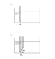
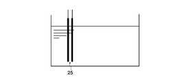
- the liquid level sensor unit monitors whether a certain amount or more of the urea aqueous solution remains in the tank, as shown in FIG. 2A, only one detection unit 25 including a pair of electrodes is provided. If the liquid level sensor unit needs to grasp the remaining amount of the urea aqueous solution more finely, as shown in FIG. 2 (b), a plurality of detection units 25a to 25c each composed of a pair of electrodes, What is necessary is just to provide with different height.
- the liquid level sensor unit of the present embodiment is not only the result of whether or not the urea aqueous solution exists up to the height at which the detection unit is disposed, but also the voltage value V generated when a voltage is applied to the detection unit. Output all.
- This voltage value V is used to calculate the relative dielectric constant ⁇ of the medium existing between the pair of electrodes in the liquid level sensor value processing unit of the DCU 60 described later.
- liquid level sensor unit of the sensor unit 54 of the present embodiment a liquid level sensor of a type that detects whether or not liquid exists up to the height position by a detection unit arranged at a predetermined height position.
- a liquid level sensor of a type that finely detects the remaining amount of liquid based on the capacitance value that continuously changes in accordance with the remaining amount of liquid is used, This will be described in the embodiment. Further, in the case of a liquid level sensor unit in which a plurality of detection units each including a pair of electrodes are arranged at different heights, the voltage value V generated between the electrodes of each detection unit is compared with each other.
- the liquid level sensor unit It is possible to perform rationality diagnosis by the level sensor unit itself, but in the case of a liquid level sensor constituted by only one detection unit, such as the liquid level sensor unit of this embodiment, the liquid level sensor unit The present invention is particularly effective because the rational diagnosis cannot be performed by itself.
- Temperature sensor unit The temperature sensor unit of the sensor unit 54 immerses the heating resistor in the liquid, detects the heating resistance value according to the temperature of the liquid, calculates the temperature t of the liquid, and outputs it.
- the concentration sensor, the liquid level sensor, and the temperature sensor are configured as sensor units, the electrodes, the heating resistors, and the like that constitute each sensor unit are usually configured to be shared with each other.
- the DCU 60 that controls the injection of urea aqueous solution has a function as a rationality diagnostic device for the sensor unit 54.
- This DCU 60 basically controls the operation of the reducing agent injection valve 31 based on various information existing on the CAN 65 so that an appropriate amount of urea aqueous solution is supplied into the exhaust pipe 11. It is. Specifically, the DCU 60 continuously reads information on the pressure of the reducing agent in the first supply path 58, and feedback-controls the pump 41 based on this pressure information, whereby the first supply path 58 is obtained.
- the internal pressure is maintained at a substantially constant value, and the injection amount of the urea aqueous solution is calculated based on the NO x amount discharged from the internal combustion engine, the temperature of the reduction catalyst, and the like, and the reducing agent injection valve 31 is opened and closed. Take control.
- the sensor unit 54 provided in the tank 50 plays an important role in reducing and purifying of the NO X in the exhaust gas is monitored whether the condition efficiently performed by injected urea aqueous solution Therefore, when there is a possibility that the rationality of the sensor unit 54 is lost, it is necessary to replace the sensor unit 54 promptly. Therefore, the DCU 60 provided in the exhaust gas purification apparatus 10 shown in FIG. 1 is provided with a rationality diagnosis unit (denoted as “rationality diagnosis” in FIG. 1) of the sensor unit.
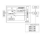
- FIG. 3 shows an example of the configuration of functional blocks related to the rationality diagnosis unit of the DCU 60 shown in FIG.
- the rationality diagnosis unit includes a CAN information extraction and generation unit (indicated as “CAN information extraction” in FIG. 3), a liquid level sensor value processing unit (indicated as “TnkLvl processing” in FIG. 3), and rationality determination. Part (indicated as “rationality determination” in FIG. 3), a counter, and the like. Specifically, each of these units is realized by executing a program by a microcomputer (not shown).
- the CAN information extraction and generation unit receives information existing on the CAN 65 including signals from the respective sensor units of the sensor unit 54 and transmits the information to other parts of the DCU 60.
- the liquid level sensor value processing unit calculates the relative dielectric constant ⁇ of the medium based on the voltage value V as the liquid level sensor value transmitted from the CAN information extraction and generation unit, and the calculation result of the relative dielectric constant ⁇ is calculated. Send to the rationality judgment unit.
- the value of the relative dielectric constant ⁇ calculated by the liquid level sensor value processing unit varies depending on the state of the medium in the tank.
- the electrostatic capacity C is obtained with reference to a map indicating the relationship between the voltage value V and the electrostatic capacity C stored in advance.
- the relative permittivity ⁇ calculated in this way is stored in advance, the relative permittivity ⁇ air of air, the relative permittivity ⁇ diesel of light oil, the relative permittivity ⁇ ureaice of the frozen urea aqueous solution, the urea aqueous solution in the liquefied state
- the state of the medium is determined by illuminating each value of the relative dielectric constant ⁇ ureawtr.
- the sensor unit 54 calculates the thermal conductivity ⁇ of the medium based on the sensor value of the concentration sensor unit, and calculates the temperature t of the medium based on the sensor value of the temperature sensor unit. Therefore, the DCU 60 is not provided with a portion for processing the density sensor value and the temperature sensor value. However, the sensor unit 54 includes a part for calculating the thermal conductivity ⁇ of the medium based on the sensor value of the concentration sensor part and a part for calculating the temperature t of the medium based on the sensor value of the temperature sensor part. If not, the DCU 60 is provided with a concentration sensor value processing unit and a temperature sensor value processing unit, and the calculated thermal conductivity ⁇ and temperature t are transmitted to the rationality determination unit. When the density sensor value processing unit of the DCU 60 calculates the thermal conductivity ⁇ of the medium, the density sensor value processing unit includes the above-described calculation logic of the thermal conductivity ⁇ provided in the density sensor unit.
- the rationality determination unit does not lose the rationality of any one of the sensor units of the sensor unit 54 provided in the tank based on the output information ⁇ , ⁇ , t. Judgment is made. That is, the rationality determination unit determines whether the tank is empty, light oil is stored, or the urea aqueous solution is frozen based on the calculated values of thermal conductivity ⁇ and relative dielectric constant ⁇ . Whether the temperature of the medium in the tank exceeds the freezing temperature of the urea aqueous solution, or whether the urea aqueous solution is in a liquefied state. It is possible to determine whether the temperature is lower than the temperature.
- the rationality determination unit determines whether there is a contradiction in the state of the medium determined mainly by the thermal conductivity ⁇ and the relative dielectric constant ⁇ of the medium, and the urea aqueous solution is frozen or the urea aqueous solution is liquefied. If it is determined that the state is the state, it is further determined whether there is a contradiction between the state of the urea aqueous solution and the temperature t of the medium.
- the rationality determination unit determines that the rationality of each sensor unit of the sensor unit 54 is ensured. On the other hand, when there is a contradiction in the state of the medium and the temperature of the medium determined based on each sensor value, the rationality determination unit loses the rationality of one of the sensor units. It is determined that
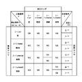
- FIG. 4 shows a correspondence table M for explaining a specific example of the rationality diagnosis for determining the rationality of the sensor unit by comparing each information ⁇ , ⁇ , t input to the rationality determination unit with each other.
- the correspondence table M is stored in the rationality determination unit of the DCU 60 shown in FIG. 3, and the contents of the information ⁇ , ⁇ , and t are compared with the correspondence table M to determine the rationality of each sensor unit of the sensor unit 54. It is used to determine whether the property is secured.
- the state of the medium is classified according to the value of the relative dielectric constant ⁇ of the medium, and in the vertical item on the left side, the state of the medium is classified according to the value of the thermal conductivity ⁇ of the medium.
- the vertical item on the right side shows whether the detected temperature t exceeds the freezing temperature of the urea aqueous solution of ⁇ 11 ° C. or below ⁇ 11 ° C. for each medium state of the concentration sensor unit. It is divided into items.
- the thermal conductivity ⁇ air of air, the thermal conductivity ⁇ diesel of light oil, the thermal conductivity ⁇ ureaice of a frozen urea aqueous solution, the thermal conductivity ⁇ ureawtr of a liquefied urea aqueous solution, and the relative dielectric constant ⁇ air of air are values obtained based on known values or by experiments in advance, respectively. Is set.
- the medium state determined by the thermal conductivity ⁇ calculated based on the sensor value of the concentration sensor unit, and the relative dielectric constant ⁇ calculated based on the sensor value of the liquid level sensor unit When there is a contradiction with the state of the medium, the rationality determination unit determines that the rationality of the sensor unit is lost (the column indicated by NG in the figure corresponds). On the other hand, even if there is no contradiction between the state of the medium determined by the thermal conductivity ⁇ and the state of the medium determined by the relative dielectric constant ⁇ , the aqueous urea solution is in a frozen or liquefied state.
- the rationality determination unit determines whether there is a contradiction with the state of the medium indicated by the temperature t of the urea aqueous solution that is the sensor value of the temperature sensor unit. That is, when the thermal conductivity ⁇ and the relative dielectric constant ⁇ indicating the urea aqueous solution in the frozen state are set, and the temperature t of the urea aqueous solution exceeds the freezing temperature, the rationality determining unit determines the rationality of the sensor unit. It is determined that the sex is lost.
- the rationality determining unit determines whether the sensor is a sensor. Judge that the rationality of the unit is lost. For the other fields indicated by OK, since the information ⁇ , ⁇ , and t obtained based on the sensor values are consistent, the rationality determination unit determines that the rationality of the sensor unit is maintained. .
- the rationality determination unit in the present embodiment counts the number of times that the rationality of the sensor unit 54 has been lost with a counter, and is equal to or more than a preset number of times, for example, continuously. When it is determined that the rationality is lost five times or more, a rationality error signal is output to the warning means. With this configuration, the possibility that a rational error of the sensor unit 54 is recognized due to a misdiagnosis is reduced. When the rational error signal of the sensor unit 54 is output, the DCU 60 generates an alarm sound to alert the driver, for example. As a result, the driver can quickly stop the internal combustion engine or repair or replace the sensor unit.
- the in-tank sensor used in this embodiment is a sensor unit 54 in which each sensor unit is integrated, it is necessary to specify which sensor unit has lost its rationality. Otherwise, the rationality diagnosis ends when the above-described rationality error is output. That is, when it is determined that the rationality of any sensor unit is lost, the sensor unit 54 needs to be repaired and replaced. However, the rationality of the sensor unit 54 is lost if any two of the concentration sensor unit, the liquid level sensor unit, and the temperature sensor unit can perform rationality diagnosis by the sensor unit itself. After that, it is determined which sensor unit has lost its rationality by performing individual rationality diagnosis.
- the concentration sensor unit and the temperature sensor unit can perform self-diagnosis. If so, it is possible to specify which sensor unit has lost its rationality.
- the rationality diagnosis of this embodiment can be adopted even when the concentration sensor, the liquid level sensor, and the temperature sensor are individually provided instead of the sensor unit 54 in which each sensor unit is integrated.
- the rationality diagnostic method for the in-tank sensor of the present embodiment can basically obtain a diagnostic result that the rationality of at least one of the three sensors is lost, It is not possible to specify which sensor is unreasonable. In this case, if at least two sensors are provided with a self-diagnosis function, a sensor whose rationality is lost is identified. Therefore, if the diagnosis method of the present embodiment is performed as a diagnosis that is always performed, and if it is diagnosed that the rationality of any sensor is lost, the self-diagnosis of individual sensors is performed. The implementation of the program can be simplified.
- the configuration of the rationality determination unit is different from the configuration of the rationality determination unit of the rationality diagnosis device according to the first embodiment.
- the following description will focus on differences from the first embodiment.
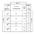
- FIG. 5 shows a correspondence table for explaining an example of rationality diagnosis according to this embodiment.
- the horizontal items in FIG. 5 are classified according to the value of the relative dielectric constant ⁇ of the medium, and the left vertical item is the thermal conductivity of the medium.
- the state of the medium is classified according to the value of the rate ⁇ .
- the vertical item on the right side indicates whether the temperature exceeds the freezing temperature ( ⁇ 11 ° C.) of the aqueous urea solution or below the freezing temperature for each medium state of the concentration sensor unit.
- the tank is empty, light oil is contained in the tank, or the urea aqueous solution is frozen.
- the urea aqueous solution is in the liquefied state or the other two items. This is because in the DCU, when the relative dielectric constant ⁇ of the medium is calculated based on the sensor value of the liquid level sensor unit, the urea aqueous solution is frozen when the tank is empty, when light oil is accommodated.
- the rationality determination unit determines that there is a discrepancy between the sensor value of the liquid level sensor and the sensor value of the concentration sensor unit. To do.
- the value of the thermal conductivity ⁇ indicating the urea aqueous solution in the liquefied state is reached, the dielectric constant indicates that the tank is empty, the light oil is contained, or the urea aqueous solution is frozen. Even in the case of the value of the rate ⁇ , the rationality determination unit determines that there is a contradiction between the sensor value of the liquid level sensor unit and the sensor value of the concentration sensor unit.
- the rationality determination unit determines that the temperature t of the urea aqueous solution, which is the sensor value of the temperature sensor unit, is It is determined whether there is a conflict with the state of the indicated medium.
- the rationality determining unit determines the rationality of the sensor unit. It is determined that the sex is lost.
- the rationality determination unit also determines the sensor unit when the temperature t of the urea aqueous solution is equal to or lower than the freezing temperature. It is judged that the rationality of is lost.
- the configuration of the in-tank sensor is not limited to the sensor unit, and a concentration sensor, a liquid level sensor, and a temperature sensor may be individually provided as in the first embodiment.
- the liquid level sensor unit may be configured to include only one detection unit including a pair of electrodes, or may be configured to include a plurality.
- the configuration of the liquid level sensor unit in the sensor unit is different from the configurations of the liquid level sensor units of the first embodiment and the second embodiment.
- the sensor unit rationality diagnosis is performed.
- the procedure for performing rationality diagnosis is different from the procedure of the first embodiment and the second embodiment. The following description will focus on differences from the first embodiment and the second embodiment.
- the liquid level sensor unit of the sensor unit used in this embodiment is a first electrode and a second electrode facing each other, and is along the height direction in the tank.
- a liquid level detector having a first electrode and a second electrode having a predetermined length, and forming a capacitor whose capacitance changes according to the liquid level of the medium between the first electrode and the second electrode.
- the first electrode and the second electrode may be plate electrodes facing each other, or may be a double tube electrode including an inner electrode and an outer electrode.
- the liquid level sensor unit used in the first and second embodiments described above is a voltage V generated when a predetermined AC voltage is applied to a detection unit composed of a pair of electrodes arranged at a predetermined height.
- the liquid level sensor unit used in the present embodiment is based on the change amount ⁇ C of the capacitance with respect to the reference capacitance C 0 when the tank is empty. The remaining amount can be recognized linearly.
- the liquid level sensor unit configured as in the present embodiment, it is possible to measure the liquid level of the urea aqueous solution, assuming that a normal urea aqueous solution is accommodated in the tank.
- the relative dielectric constant ⁇ of the medium is calculated based on the sensor value of the liquid level sensor unit, and When performing a rationality diagnosis for determining the state, it is difficult to distinguish whether the difference in capacitance is simply dependent on the state of the medium. That is, it is difficult to distinguish whether the capacitance change amount ⁇ C is caused simply by a difference in the state of the medium or by a difference in the liquid level of the medium.
- the voltage value generated when an AC voltage is applied between the first electrode and the second electrode is used as in the first embodiment and the second embodiment. It is not easy to calculate the relative dielectric constant ⁇ of the medium. For this reason, the rationality diagnosis apparatus for the in-tank sensor according to the present embodiment performs rationality diagnosis on the premise that the tank is full when the urea aqueous solution is replenished in the tank.
- the DCU of this embodiment is basically the same as the configuration of the DCU described in the first embodiment or the second embodiment.
- the determination unit is provided with a correspondence table shown in FIG. 4 or FIG.
- the rationality diagnosis method of the sensor unit of the present embodiment first, when the medium is fully replenished to the tank, the same rationality diagnosis method as described in the first embodiment or the second embodiment is performed. The method makes a rational diagnosis. Immediately after the medium is replenished, the relative permittivity ⁇ of each medium when the tank is filled with the medium is stored in the DCU in advance, so that the relative permittivity ⁇ detected by the liquid level sensor unit can be reduced. The state of the medium is determined from the value. Note that, immediately after the medium is replenished, it can be said that the inside of the tank is not empty, and the possibility that the medium is frozen is small.
- the rationality judgment unit loses the rationality of any sensor. It is determined that On the other hand, when it is determined in the rationality diagnosis immediately after the medium replenishment that the rationality of the sensor unit is maintained, the medium replenished in the tank is specified. Therefore, since the medium in the tank is clarified when performing the subsequent rationality diagnosis, even when the remaining amount of the medium in the tank is not full, it is detected by the liquid level sensor unit. The state of the medium in the tank is estimated from the value of the relative dielectric constant ⁇ .
- the DCU By specifying the type of medium while performing sex diagnosis and then performing rationality diagnosis, it is possible to determine the contradiction between the sensor values. In fact, when it is determined that the medium in the tank is light oil at the time of rationality diagnosis immediately after replenishment of the medium, it is not possible to continue using light oil instead of the urea aqueous solution as a reducing agent. A warning is issued to the driver or the like.
Landscapes
- Engineering & Computer Science (AREA)
- Chemical & Material Sciences (AREA)
- Chemical Kinetics & Catalysis (AREA)
- General Physics & Mathematics (AREA)
- Combustion & Propulsion (AREA)
- Mechanical Engineering (AREA)
- General Engineering & Computer Science (AREA)
- Physics & Mathematics (AREA)
- Toxicology (AREA)
- Health & Medical Sciences (AREA)
- Exhaust Gas After Treatment (AREA)
- Exhaust Gas Treatment By Means Of Catalyst (AREA)
- Combined Controls Of Internal Combustion Engines (AREA)
- Investigating Or Analyzing Materials By The Use Of Electric Means (AREA)
Abstract
Description
したがって、センサの修理、交換が迅速に行われ、タンク内に貯蔵された液体の状態が正確に把握される。
なお、それぞれの図中、同じ符号を付してあるものについては同一の部材を示しており、適宜説明が省略されている。
1.排気浄化装置
図1は、第1の実施の形態にかかるタンク内センサ54の合理性診断装置が備えられた内燃機関5の排気浄化装置(以下、単に「排気浄化装置」と称する場合がある。)10の構成例を示している。この排気浄化装置10は、還元剤としての尿素水溶液を、排気通路の途中に配設された還元触媒13の上流側に噴射供給し、還元触媒13において排気ガス中に含まれるNOXを選択的に還元浄化する排気浄化装置10である。当該排気浄化装置10は、内燃機関5に接続された排気管11の途中に配設され、排気ガス中に含まれるNOXを選択的に還元するための還元触媒13と、還元触媒13の上流側で排気管11内に尿素水溶液を噴射供給するための還元剤供給装置20とを主たる要素として備えている。
排気浄化装置10に備えられた還元剤供給装置20は、還元触媒13の上流側で排気管11に固定された還元剤噴射弁31と、尿素水溶液が貯蔵されたタンク50と、タンク50内の尿素水溶液を還元剤噴射弁31に対して圧送するポンプ41を含むポンプモジュール40と、排気管11内に噴射供給する還元剤の噴射制御を行うための制御装置(以下、「DCU:Dosing Control Unit」と称する。)60を備えている。また、ポンプモジュール40と還元剤噴射弁31とは第1の供給通路58によって接続され、タンク50とポンプモジュール40とは第2の供給通路57によって接続され、さらに、ポンプモジュール40とタンク50とは循環通路59によって接続されている。
なお、本実施形態では、ECU70とDCU60とが別のコントロールユニットからなり、CAN65を介して情報のやり取りができるようにされているが、これらのECU70とDCU60とが一つのコントロールユニットとして構成されても構わない。
このリバーティングバルブ71は、例えば、尿素水溶液の流路、タンク50からポンプモジュール40へ向かう順方向から、ポンプモジュール40からタンク50へ向かう逆方向に切り替える機能を持った切換弁であり、内燃機関のイグニッションスイッチがオフにされたときに、流路が逆方向に切り換えられることにより尿素水溶液がタンク50内に回収される。
(1)センサユニット
本実施形態において、タンク50には、濃度センサ、液位センサ及び温度センサの機能を併せ持ったセンサユニット54が備えられている。このセンサユニット54は、タンク50内の尿素水溶液の濃度を測定するための濃度センサ部と、タンク50内の尿素水溶液の残量を測定するための液位センサ部と、タンク50内の尿素水溶液の温度を測定するための温度センサ部とを備えている。センサユニット54の各センサ部によって検出されるセンサ値は、タンク50内の尿素水溶液の濃度、残量及び温度に関連する情報を表す信号として出力される。
例えば、尿素水溶液の噴射量を決定する際には尿素水溶液が所定範囲内の濃度に保たれていることが前提とされており、タンク内の尿素水溶液の濃度が所定範囲を超えていたり下回ったりしていると、加水分解により生成されるアンモニア量が過不足を生じるおそれがある。そのため、尿素水溶液の濃度が所定範囲内に保たれているかを監視するために濃度センサ部が備えられている。
そして、例えば、尿素水溶液の濃度や液位に異常が見られる場合には、尿素水溶液の噴射制御が停止され、さらには、内燃機関が速やかに停止されるよう警告信号が発せられたり、尿素水溶液の温度に異常が見られる場合には、上述したエンジン冷却水による尿素水溶液の温度制御が行われる。
センサユニット54を構成する各センサ部の構成は、公知のセンサの構成が用いられているが、以下、各センサ部によって媒体の濃度や液位、温度を測定する測定原理の一例を簡単に説明する。
センサユニット54の濃度センサ部は、液体に浸漬された濃度センサ素子に設けられた発熱抵抗体に所定の時間定電流を流して濃度センサ素子の周囲の媒体を加熱するとともに、所定時間の通電による発熱抵抗体の両端の電圧変化を検知して、液体の濃度を算出し出力するよう構成されたものである。
すなわち、濃度センサ部は、通電開始直後に発熱抵抗体の抵抗値に対応して出力された電圧値V1と、所定時間経過後に発熱抵抗体の抵抗値に対応して出力された電圧値V2との差分ΔV(V2-V1)をあらかじめ記憶したさまざまな濃度の尿素水溶液に対応するΔVの値に照らして、尿素水溶液の濃度を判別して出力する。
限定する主旨ではないが、一例として、空気の熱伝導率λair≒0.0241、軽油の熱伝導率λdiesel≒0.07~0.17、凍結した32.5%尿素水溶液の熱伝導率λureaice≒0.75、液化した32.5%尿素水溶液の熱伝導率λureawtr≒0.57であることが一般的に知られている。
センサユニット54の液位センサ部は、所定の高さに配置された一対の電極からなる検出部に所定の交流電圧を印加し、このときに流れる電流を変換して得られた電圧が所定値以上になっているか否かを検知することによって、媒体の残量を監視するように構成されたものである。すなわち、尿素水溶液の比誘電率は、空気や軽油、凍結した尿素水溶液の比誘電率よりも著しく高いことから、液位センサ部は、電極間に尿素水溶液が介在する場合には電極間に所定値以上の電圧が発生することを利用して、当該一対の電極が配置された高さ位置まで液体が存在しているか否かを検知して、出力する。
例えば、液位センサ部がある一定量以上の尿素水溶液がタンク内に残っているかを監視するのであれば、図2(a)に示すように一対の電極からなる検出部25が一つだけ設けられればよいし、液位センサ部がより細かく尿素水溶液の残量を把握したいのであれば、図2(b)に示すようにそれぞれ一対の電極からなる複数の検出部25a~25cが、それぞれ高さを異ならせて設けられればよい。
また、一対の電極からなる検出部を、高さを異ならせて複数配置した液位センサ部の場合には、それぞれの検出部の電極間に発生した電圧値Vを互いに比較することによって、液位センサ部自身で合理性診断を行うことも可能であるが、本実施形態の液位センサ部のように、一つの検出部のみによって構成される液位センサの場合には、液位センサ部自身での合理性診断ができないために、本発明が特に有効となる。
センサユニット54の温度センサ部は、液体に発熱抵抗体を浸漬させ、液体の温度に応じた発熱抵抗値を検知して、液体の温度tを算出して出力する。
なお、濃度センサ、液位センサ及び温度センサをセンサユニットとして構成する場合には、通常、各センサ部を構成する電極や発熱抵抗体等の一部が互いに共有化されて構成される。
本実施形態においては、尿素水溶液の噴射制御を行うDCU60が、センサユニット54の合理性診断装置としての機能を有している。このDCU60は、基本的には、適切な量の尿素水溶液が排気管11中に供給されるように、CAN65上に存在する様々な情報をもとに還元剤噴射弁31の動作制御を行う装置である。
具体的には、DCU60は、第1の供給経路58内の還元剤の圧力に関する情報を継続的に読み込み、この圧力情報をもとにポンプ41をフィードバック制御することにより、第1の供給経路58内の圧力がほぼ一定の値に維持されるとともに、内燃機関から排出されるNOX量や還元触媒の温度等をもとにして尿素水溶液の噴射量を演算し、還元剤噴射弁31の開閉制御を行う。
なお、参考までに、空気の比誘電率εair≒1.0、軽油の比誘電率εdiesel≒1.8、凍結した水すなわち氷の比誘電率ε≒4.2、液体の水の比誘電率ε≒80であることが一般的に知られている。
ただし、センサユニット54に、濃度センサ部のセンサ値をもとに媒体の熱伝導率λを算出する部分や、温度センサ部のセンサ値をもとに媒体の温度tを算出する部分を備えていない場合には、DCU60に、濃度センサ値処理部や温度センサ値処理部が備えられ、算出される熱伝導率λ及び温度tが合理性判定部に送信される。
DCU60の濃度センサ値処理部で媒体の熱伝導率λを算出する場合には、上述した濃度センサ部に備えられた熱伝導率λの算出ロジックが、濃度センサ値処理部に備えられる。
図4の横の項目には、媒体の比誘電率εの値によって媒体の状態が項目分けされており、左側の縦の項目には、媒体の熱伝導率λの値によって媒体の状態が項目分けされており、右側の縦の項目には、濃度センサ部の媒体の状態ごとに、検出された温度tが尿素水溶液の凍結温度である-11℃を超えるか-11℃以下であるかが項目分けされている。
これ以外のOKで示される欄については、各センサ値をもとに得られる情報λ、ε、tに矛盾がないため、合理性判定部はセンサユニットの合理性が保たれていると判定する。
センサユニット54の合理性エラー信号が出力されたときには、DCU60は、例えば、運転者に対して注意を喚起するために警報音を発生させる。これによって、運転者は内燃機関を速やかに停止させたり、センサユニットの修理交換を行ったりすることができる。
ただし、濃度センサ部、液位センサ部及び温度センサ部のうち、いずれか二つのセンサ部が、センサ部自身で合理性診断を行うことができるのであれば、センサユニット54の合理性が失われていると判定された後、個別の合理性診断が行われることによって、どのセンサ部の合理性が失われているかが特定される。例えば、上述したように、本実施形態のセンサユニット54では、液位センサ部自身で液位センサ部の合理性診断を行うことができないことから、濃度センサ部及び温度センサ部が自己診断できるものであれば、どのセンサ部の合理性が失われているかを特定することができる。
したがって、常時行う診断として本実施形態の診断方法を実施し、いずれかのセンサの合理性が失われていると診断されたときに、個別のセンサの自己診断を実施するようにすれば、診断プログラムの実施の簡素化を図ることができる。
本発明の第2の実施の形態にかかる合理性診断装置は、合理性判定部の構成が第1の実施の形態の合理性診断装置の合理性判定部の構成と異なっている。
以下、第1の実施の形態と異なる点を中心に説明する。
したがって、本実施形態では、合理性判定部は、液位センサ処理部から出力される比誘電率の値に基づいて、タンク内に液化状態の尿素水溶液が収容されているか(ε=εureawtr)、それ以外か(ε≦εureaice)を判別する。
本発明の第3の実施の形態の合理性診断装置は、センサユニットのうちの液位センサ部の構成が第1の実施の形態及び第2の実施の形態の液位センサ部の構成と異なるセンサユニットの合理性診断を行うものである。また、液位センサ部の構成が異なることに伴い、合理性診断を行う際の手順が第1の実施の形態及び第2の実施の形態の手順とは異なっている。
以下、第1の実施の形態及び第2の実施の形態と異なる点を中心に説明する。
本実施形態で用いられるセンサユニットの液位センサ部は、図6に示すように、互いに対向する第1電極及び第2電極であって、タンク内の高さ方向に沿って所定長さを有する第1電極及び第2電極を有し、第1電極と第2電極との間で媒体の液位に応じて静電容量が変化するコンデンサを形成した液位検出体を備えている。この第1電極及び第2電極は、対向する平板電極であってもよく、内側電極及び外側電極からなる二重管電極であってもよい。
上述した第1及び第2の実施の形態で用いられている液位センサ部は、所定高さに配置される一対の電極からなる検出部に所定の交流電圧を印加したときに発生する電圧Vが所定値以上となったときに、当該所定高さまで媒体が存在することを認識する。これに対して、本実施形態で用いられている液位センサ部は、タンク内が空である状態での基準静電容量C0に対する静電容量の変化量ΔCをもとにして、媒体の残量をリニアに認識することができる。
しかしながら、タンク内の液体の残量によって、液体中に浸漬される電極の面積が異なってくることから、液位センサ部のセンサ値をもとに媒体の比誘電率εを算出して媒体の状態を判別する合理性診断を行う場合、静電容量の違いが、単純に媒体の状態に依存するものであるかの見分けが困難である。すなわち、静電容量の変化量ΔCが、単純に媒体の状態の違いによって生じているのか、媒体の液位の違いによって生じているのかの見分けが困難である。
本実施形態のDCUも、基本的には第1の実施の形態又は第2の実施の形態で説明したDCUの構成と同様であり、合理性判定部には図4又は図5に示す対応表が備えられている。
本実施形態のセンサユニットの合理性診断方法では、まず、タンクに媒体を満タンに補充した時点で、第1の実施の形態又は第2の実施の形態で説明した合理性診断方法と同様の方法で合理性診断が行われる。媒体の補充直後の場合、タンク内が媒体で満タンとされた場合の各媒体の比誘電率εを予めDCUに記憶させておくことにより、液位センサ部によって検出される比誘電率εの値から媒体の状態が判別される。
なお、媒体の補充直後の場合、タンク内が空でないことは言うまでもなく、媒体が凍結しているおそれも少ないと言うことができる。
なお、実際には、媒体の補充直後の合理性診断時にタンク内の媒体が軽油であると判別される際には、還元剤として尿素水溶液の代わりに軽油を使用し続けることができないことから、運転者等に対して警告が発せられることになる。
Claims (6)
- 液体を貯蔵するためのタンク内に備えられた濃度センサ、液位センサ及び温度センサの合理性診断を行うためのタンク内センサの合理性診断方法において、
前記濃度センサ、前記液位センサ及び前記温度センサによって検出される各センサ値に矛盾が生じていないかを判定することによって、前記濃度センサ、前記液位センサ及び前記温度センサのうちのいずれかのセンサの合理性が失われていないかを診断することを特徴とするタンク内センサの合理性診断方法。 - 前記各センサ値をもとにセンサ値ごとに前記液体の状態を判別し、前記液体の状態に矛盾が生じていないかを判定することによって、前記合理性診断を行うことを特徴とする請求の範囲の第1項に記載のタンク内センサの合理性診断方法。
- 前記濃度センサ及び前記液位センサのセンサ値をもとに、前記液体が凍結、液化、不足のうちのどの状態にあるべきかの判別を行うとともに、前記温度センサのセンサ値をもとに、前記液体が凍結、液状のいずれの状態にあるべきかの判別を行い、各液体の状態に矛盾が生じていないかを判定することを特徴とする請求の範囲の第2項に記載のタンク内センサの合理性診断方法。
- 前記濃度センサのセンサ値をもとに得られる熱伝導率の値をもとにして、前記合理性診断を行うことを特徴とする請求の範囲の第1項~第3項のいずれか一項に記載のタンク内センサの合理性診断方法。
- 前記液位センサのセンサ値をもとに得られる比誘電率の値をもとにして、前記合理性診断を行うことを特徴とする請求の範囲の第1項~第3項のいずれか一項に記載のタンク内センサの合理性診断方法。
- 液体を貯蔵するためのタンク内に備えられた濃度センサ、液位センサ及び温度センサの合理性診断を行うためのタンク内センサの合理性診断装置において、
前記濃度センサのセンサ値をもとに得られる前記液体の状態を示す第1の信号と、前記液位センサのセンサ値をもとに得られる前記液体の状態を示す第2の信号と、前記温度センサのセンサ値をもとに得られる前記液体の状態を示す第3の信号と、を相互に比較し、前記液体の状態に矛盾が生じていないかを判定することによって、前記濃度センサ、前記液位センサ及び前記温度センサのうちのいずれかのセンサの合理性が失われていないかを診断する合理性判定部を備えることを特徴とするタンク内センサの合理性診断装置。
Priority Applications (2)
| Application Number | Priority Date | Filing Date | Title |
|---|---|---|---|
| CN2008801286776A CN102007276B (zh) | 2008-06-27 | 2008-10-14 | 箱内传感器的合理性诊断方法以及合理性诊断装置 |
| US13/000,709 US8746030B2 (en) | 2008-06-27 | 2008-10-14 | Rationality diagnosis method and rationality diagnosis apparatus for sensor inside tank |
Applications Claiming Priority (2)
| Application Number | Priority Date | Filing Date | Title |
|---|---|---|---|
| JP2008168194A JP5152912B2 (ja) | 2008-06-27 | 2008-06-27 | タンク内センサの合理性診断方法及び合理性診断装置 |
| JP2008-168194 | 2008-06-27 |
Publications (1)
| Publication Number | Publication Date |
|---|---|
| WO2009157102A1 true WO2009157102A1 (ja) | 2009-12-30 |
Family
ID=41444177
Family Applications (1)
| Application Number | Title | Priority Date | Filing Date |
|---|---|---|---|
| PCT/JP2008/068528 Ceased WO2009157102A1 (ja) | 2008-06-27 | 2008-10-14 | タンク内センサの合理性診断方法及び合理性診断装置 |
Country Status (4)
| Country | Link |
|---|---|
| US (1) | US8746030B2 (ja) |
| JP (1) | JP5152912B2 (ja) |
| CN (1) | CN102007276B (ja) |
| WO (1) | WO2009157102A1 (ja) |
Cited By (4)
| Publication number | Priority date | Publication date | Assignee | Title |
|---|---|---|---|---|
| JP2010168978A (ja) * | 2009-01-22 | 2010-08-05 | Mazda Motor Corp | エンジンの排気浄化装置 |
| US20120006003A1 (en) * | 2010-07-08 | 2012-01-12 | Gm Global Technology Operations, Inc. | Method of operating a vehicle under frozen diesel emission fluid conditions |
| CN102906404A (zh) * | 2010-05-25 | 2013-01-30 | 五十铃自动车株式会社 | Scr系统 |
| CN104632489A (zh) * | 2013-11-08 | 2015-05-20 | 法国大陆汽车公司 | 用于确定喷射器是否处于阻滞状态的方法 |
Families Citing this family (28)
| Publication number | Priority date | Publication date | Assignee | Title |
|---|---|---|---|---|
| DE102008001919B4 (de) * | 2008-05-21 | 2017-08-03 | Robert Bosch Gmbh | Verfahren zur Plausibilisierung eines Temperatursensors |
| JP5176974B2 (ja) * | 2009-01-19 | 2013-04-03 | マツダ株式会社 | エンジンの排気浄化装置 |
| US8417188B1 (en) * | 2009-02-03 | 2013-04-09 | Irobot Corporation | Systems and methods for inspection and communication in liquid petroleum product |
| JP4978635B2 (ja) * | 2009-02-12 | 2012-07-18 | 株式会社デンソー | 排気浄化システムの制御装置 |
| JP5585125B2 (ja) * | 2010-02-26 | 2014-09-10 | いすゞ自動車株式会社 | 尿素品質診断システム |
| DE102010011151A1 (de) * | 2010-03-11 | 2011-09-15 | Emitec Gesellschaft Für Emissionstechnologie Mbh | Tank und Verfahren zur Bestimmung des Füllstands im Tank |
| US8505371B2 (en) | 2011-11-30 | 2013-08-13 | Ford Global Technologies, Llc | Methods for an exhaust fluid sensor |
| DE102012004269A1 (de) * | 2012-03-02 | 2013-09-05 | Emitec Gesellschaft Für Emissionstechnologie Mbh | Fördereinheit für ein flüssiges Additiv zur Abgasnachbehandlung |
| JP5900608B2 (ja) * | 2012-04-18 | 2016-04-06 | トヨタ自動車株式会社 | 液体の残量検出装置 |
| US9333466B2 (en) | 2012-12-05 | 2016-05-10 | Cummins Powergen Ip, Inc. | Diesel exhaust fluid injector assembly |
| US9221016B2 (en) | 2012-12-05 | 2015-12-29 | Cummins Cal Pacific, Llc | Exhaust aftertreatment packaging for a diesel genset |
| US8806853B2 (en) * | 2012-12-05 | 2014-08-19 | Cummins Powergen Ip, Inc. | System and method for SCR inducement |
| US9771847B2 (en) | 2012-12-05 | 2017-09-26 | Cummins Cal Pacific, Llc | Integrated load bank and exhaust heater system with load shed capability for a diesel genset exhaust aftertreatment system |
| US9482154B2 (en) | 2012-12-05 | 2016-11-01 | Cummins Cal Pacific, Llc | Exhaust gas collector for an exhaust aftertreatment system |
| US20140166126A1 (en) * | 2012-12-17 | 2014-06-19 | Deere & Company | Reductant delivery system |
| KR20140087369A (ko) * | 2012-12-28 | 2014-07-09 | 현대자동차주식회사 | 요소 레벨 센서의 고장 진단 방법 및 장치 |
| WO2014199777A1 (ja) * | 2013-06-10 | 2014-12-18 | ボッシュ株式会社 | 制御装置、内燃機関の排気浄化装置及び排気浄化装置の制御方法 |
| JP6105403B2 (ja) * | 2013-06-17 | 2017-03-29 | 日野自動車株式会社 | 尿素水供給系の診断装置 |
| US9050561B1 (en) | 2014-03-26 | 2015-06-09 | GM Global Technology Operations LLC | Reductant quality system including rationality diagnostic |
| CN103990194B (zh) * | 2014-04-29 | 2016-06-15 | 昆山韦睿医疗科技有限公司 | 一种透析液温度监测方法、装置及腹膜透析仪 |
| US9845717B2 (en) * | 2014-10-28 | 2017-12-19 | Ford Global Technologies, Llc | Systems and methods for managing diesel exhaust fluid stratification |
| GB2528601A (en) * | 2015-10-16 | 2016-01-27 | Gm Global Tech Operations Inc | A method of managing a selective catalytic reduction system of a motor vehicle |
| DE102015013877B3 (de) * | 2015-10-28 | 2016-12-22 | Audi Ag | Verfahren zum Betreiben einer Fluidbehälteranordnung sowie entsprechende Fluidbehälteranordnung |
| EP3369902B1 (en) * | 2017-03-03 | 2020-04-22 | MEAS France | Method and system for determining the validity of a measured concentration of urea in a fluid |
| CN110735695B (zh) * | 2018-07-18 | 2022-09-27 | 罗伯特·博世有限公司 | Scr系统及其控制器、控制方法及具有其的可读存储介质 |
| DE102018216402B4 (de) * | 2018-09-26 | 2026-01-15 | Robert Bosch Gmbh | Verfahren zur Qualitätserkennung eines Reduktionsmittels |
| JP7320194B2 (ja) * | 2019-11-25 | 2023-08-03 | いすゞ自動車株式会社 | 車両の還元剤解凍装置 |
| CN113030399B (zh) * | 2021-03-29 | 2024-02-20 | 潍柴动力股份有限公司 | 尿素浓度的确定方法及装置 |
Citations (3)
| Publication number | Priority date | Publication date | Assignee | Title |
|---|---|---|---|---|
| JPH039057A (ja) * | 1989-06-02 | 1991-01-16 | Hino Motors Ltd | アクセル変位量検出器 |
| JPH08189412A (ja) * | 1995-01-11 | 1996-07-23 | Fuji Heavy Ind Ltd | エンジン制御用センサの異常検出方法 |
| JP2007056741A (ja) * | 2005-08-24 | 2007-03-08 | Nissan Diesel Motor Co Ltd | エンジンの排気浄化装置 |
Family Cites Families (12)
| Publication number | Priority date | Publication date | Assignee | Title |
|---|---|---|---|---|
| JP2536554B2 (ja) * | 1987-10-27 | 1996-09-18 | トヨタ自動車株式会社 | エンジンマウンティング装置 |
| JPH0713004U (ja) * | 1993-07-07 | 1995-03-03 | 曙ブレーキ工業株式会社 | 車両用検出手段の異常検出装置 |
| JPH08138182A (ja) * | 1994-11-08 | 1996-05-31 | Japan Aviation Electron Ind Ltd | 液量取引計量装置 |
| KR100373043B1 (ko) | 2000-12-05 | 2003-02-15 | 현대자동차주식회사 | 자동차용 연료준위 센서의 고장 진단방법 |
| CN100416054C (zh) * | 2003-10-22 | 2008-09-03 | 日产柴油机车工业株式会社 | 发动机控制装置和发动机运转方法 |
| JP3687915B2 (ja) * | 2003-10-27 | 2005-08-24 | 日産ディーゼル工業株式会社 | 液体判別装置 |
| JP3687916B2 (ja) * | 2003-10-28 | 2005-08-24 | 日産ディーゼル工業株式会社 | エンジンの排気浄化装置 |
| JP4594278B2 (ja) * | 2005-07-08 | 2010-12-08 | 日本特殊陶業株式会社 | 液体状態検知センサ |
| US7665347B2 (en) * | 2005-11-11 | 2010-02-23 | Ngk Spark Plug Co., Ltd. | Liquid state detecting apparatus |
| JP4698499B2 (ja) * | 2006-06-21 | 2011-06-08 | Necフィールディング株式会社 | 観賞魚水槽内環境監視システム及びその方法並びにそれに用いる水槽セット及び監視サーバ |
| DE102007053092A1 (de) * | 2006-11-08 | 2008-07-10 | Yamaha Hatsudoki K.K., Iwata | Brennstoffzellensystem und eine solche umfassende Transportausstattung |
| JP4297379B2 (ja) * | 2007-02-02 | 2009-07-15 | ボッシュ株式会社 | Noxセンサの故障診断装置及び故障診断方法 |
-
2008
- 2008-06-27 JP JP2008168194A patent/JP5152912B2/ja not_active Expired - Fee Related
- 2008-10-14 WO PCT/JP2008/068528 patent/WO2009157102A1/ja not_active Ceased
- 2008-10-14 US US13/000,709 patent/US8746030B2/en not_active Expired - Fee Related
- 2008-10-14 CN CN2008801286776A patent/CN102007276B/zh not_active Expired - Fee Related
Patent Citations (3)
| Publication number | Priority date | Publication date | Assignee | Title |
|---|---|---|---|---|
| JPH039057A (ja) * | 1989-06-02 | 1991-01-16 | Hino Motors Ltd | アクセル変位量検出器 |
| JPH08189412A (ja) * | 1995-01-11 | 1996-07-23 | Fuji Heavy Ind Ltd | エンジン制御用センサの異常検出方法 |
| JP2007056741A (ja) * | 2005-08-24 | 2007-03-08 | Nissan Diesel Motor Co Ltd | エンジンの排気浄化装置 |
Cited By (6)
| Publication number | Priority date | Publication date | Assignee | Title |
|---|---|---|---|---|
| JP2010168978A (ja) * | 2009-01-22 | 2010-08-05 | Mazda Motor Corp | エンジンの排気浄化装置 |
| CN102906404A (zh) * | 2010-05-25 | 2013-01-30 | 五十铃自动车株式会社 | Scr系统 |
| CN102906404B (zh) * | 2010-05-25 | 2015-04-22 | 五十铃自动车株式会社 | Scr系统 |
| US20120006003A1 (en) * | 2010-07-08 | 2012-01-12 | Gm Global Technology Operations, Inc. | Method of operating a vehicle under frozen diesel emission fluid conditions |
| US9797288B2 (en) * | 2010-07-08 | 2017-10-24 | GM Global Technology Operations LLC | Method of operating a vehicle under frozen diesel emission fluid conditions |
| CN104632489A (zh) * | 2013-11-08 | 2015-05-20 | 法国大陆汽车公司 | 用于确定喷射器是否处于阻滞状态的方法 |
Also Published As
| Publication number | Publication date |
|---|---|
| JP2010007568A (ja) | 2010-01-14 |
| US20110107812A1 (en) | 2011-05-12 |
| JP5152912B2 (ja) | 2013-02-27 |
| US8746030B2 (en) | 2014-06-10 |
| CN102007276A (zh) | 2011-04-06 |
| CN102007276B (zh) | 2013-05-29 |
Similar Documents
| Publication | Publication Date | Title |
|---|---|---|
| JP5152912B2 (ja) | タンク内センサの合理性診断方法及び合理性診断装置 | |
| JP5471831B2 (ja) | Scrシステム | |
| ES2381706T3 (es) | Procedimiento y dispositivo para el control de un inyector | |
| US7776265B2 (en) | System for diagnosing reagent solution quality | |
| US8303174B2 (en) | Temperature sensor plausibility diagnosis unit and plausibility diagnosis method and internal combustion engine exhaust purification apparatus | |
| US9032712B2 (en) | Method for heating a delivery system and motor vehicle having a delivery system | |
| JP6127510B2 (ja) | 尿素scr用尿素水消費量診断装置 | |
| JP6307595B2 (ja) | 再循環式排気処理流体システム | |
| JP5789925B2 (ja) | NOxセンサ診断装置及びSCRシステム | |
| US9188042B2 (en) | Urea quality diagnosis system | |
| CN105612322B (zh) | 用于在scr废气后处理系统中检查温度传感器的方法 | |
| US9016043B2 (en) | Exhaust treatment system with urea temperature rationality diagnostic | |
| CN105658920A (zh) | Scr系统、scr传感器以及液位传感器 | |
| JP2014145275A (ja) | 尿素scr用尿素水消費量診断装置 | |
| JP6127509B2 (ja) | 尿素scr用尿素水消費量診断装置 | |
| JPWO2009008408A1 (ja) | 液体凝固点識別装置、およびそれを用いた液体貯留タンクの凝固防止装置、ならびに自動車の排気ガスの低減装置 | |
| JP2012002060A (ja) | 尿素品質診断システム | |
| JP2019073976A (ja) | 診断装置及び診断方法 | |
| JP2009197710A (ja) | 添加剤実噴射量検証装置、添加剤供給装置の異常判定装置、及び添加剤供給装置の噴射制御装置 | |
| CN113677876B (zh) | 用于柴油机排气处理液输送系统的控制系统 | |
| JP2011241722A (ja) | 排ガス浄化システム | |
| WO2016171029A1 (ja) | 液位センサの異常検出装置及び異常検出方法 | |
| HK1234806B (zh) | 用於在内燃机的运行中颗粒过滤器的再生的方法 |
Legal Events
| Date | Code | Title | Description |
|---|---|---|---|
| WWE | Wipo information: entry into national phase |
Ref document number: 200880128677.6 Country of ref document: CN |
|
| 121 | Ep: the epo has been informed by wipo that ep was designated in this application |
Ref document number: 08874802 Country of ref document: EP Kind code of ref document: A1 |
|
| WWE | Wipo information: entry into national phase |
Ref document number: 13000709 Country of ref document: US |
|
| NENP | Non-entry into the national phase |
Ref country code: DE |
|
| 122 | Ep: pct application non-entry in european phase |
Ref document number: 08874802 Country of ref document: EP Kind code of ref document: A1 |