WO2009150892A1 - モータサイクル用クラッチ装置 - Google Patents
モータサイクル用クラッチ装置 Download PDFInfo
- Publication number
- WO2009150892A1 WO2009150892A1 PCT/JP2009/057375 JP2009057375W WO2009150892A1 WO 2009150892 A1 WO2009150892 A1 WO 2009150892A1 JP 2009057375 W JP2009057375 W JP 2009057375W WO 2009150892 A1 WO2009150892 A1 WO 2009150892A1
- Authority
- WO
- WIPO (PCT)
- Prior art keywords
- clutch
- rotating body
- clutch device
- contact portion
- coil spring
- Prior art date
- Legal status (The legal status is an assumption and is not a legal conclusion. Google has not performed a legal analysis and makes no representation as to the accuracy of the status listed.)
- Ceased
Links
Images

Classifications
-
- F—MECHANICAL ENGINEERING; LIGHTING; HEATING; WEAPONS; BLASTING
- F16—ENGINEERING ELEMENTS AND UNITS; GENERAL MEASURES FOR PRODUCING AND MAINTAINING EFFECTIVE FUNCTIONING OF MACHINES OR INSTALLATIONS; THERMAL INSULATION IN GENERAL
- F16D—COUPLINGS FOR TRANSMITTING ROTATION; CLUTCHES; BRAKES
- F16D13/00—Friction clutches
- F16D13/22—Friction clutches with axially-movable clutching members
- F16D13/38—Friction clutches with axially-movable clutching members with flat clutching surfaces, e.g. discs
- F16D13/52—Clutches with multiple lamellae ; Clutches in which three or more axially moveable members are fixed alternately to the shafts to be coupled and are pressed from one side towards an axially-located member
- F16D13/54—Clutches with multiple lamellae ; Clutches in which three or more axially moveable members are fixed alternately to the shafts to be coupled and are pressed from one side towards an axially-located member with means for increasing the effective force between the actuating sleeve or equivalent member and the pressure member
- F16D13/56—Clutches with multiple lamellae ; Clutches in which three or more axially moveable members are fixed alternately to the shafts to be coupled and are pressed from one side towards an axially-located member with means for increasing the effective force between the actuating sleeve or equivalent member and the pressure member in which the clutching pressure is produced by springs only
Definitions
- clutch plates are brought into pressure contact with a pressing member such as a spring through a pressure plate, whereby the rotation of the crankshaft is transmitted to the transmission side.
- a pressing member such as a spring
- the release mechanism is operated by the driver operating the clutch lever, and the release mechanism presses the pressing member against the clutch plate, and the first and Power transmission between the second clutch plates is cut off.
- the fixed portion extends radially inward from the end of the second contact portion, the strength of the second contact portion and the fixed portion with respect to centrifugal force can be increased. For this reason, a 2nd contact part and a fixing
- the rotational dimension of the first opening 84 is substantially the same as the free length of the first coil spring 12, but is larger than the free length of the second coil spring 13. That is, the free length of the second coil spring 13 is smaller than the free length of the first coil spring 12. For this reason, a gap is secured in the rotational direction between the second coil spring 13 and the edge of the first opening 84. Thereby, after the compression of the first coil spring 12 is started, the compression of the second coil spring 13 is started. That is, with these configurations, the torsional characteristics of the damper mechanism D can be made in two stages.
- the long hole 86 is a space in which a second contact portion 93 (described later) of the retaining plate 9 moves in the rotation direction, and is formed between the rotation directions of the adjacent first contact portions 87.
- a second contact portion 93 is disposed in the long hole 86.
- the radial position of the long hole 86 is substantially the same as the radial position of the first contact portion 87.
- the long hole 86 extends to the outside of the first opening 84 in the radial direction. That is, when viewed from the radial direction, the end of the long hole 86 overlaps the end of the first opening 84.
- the clutch housing 7 is a member made of, for example, a sheet metal, and is disposed outside the input gear 8 in the axial direction.
- the clutch housing 7 has a housing main body 71 and a connecting portion 72 provided on the outer peripheral portion of the housing main body 71.
- the retaining plate 9 is a sheet metal member fixed to the clutch housing 7, and is disposed on the inner side in the axial direction of the input gear 8.
- the retaining plate 9 has a retaining plate main body 94 and a stopper portion 99 provided on the outer peripheral portion of the retaining plate main body 94.
- the outer peripheral portion of the retaining plate main body 94 can contact the second protrusion 83 in the axial direction.
- the stopper part 99 is a part that constitutes the stopper mechanism S together with the first contact part 87, and has a second contact part 93 and a fixing part 95.
- the second contact portion 93 extends in the axial direction from the outer peripheral portion of the retaining plate main body 94.
- the fixing portion 95 extends radially inward from the end portion of the second contact portion 93 and is fixed to the housing body 71 by the rivet 18.
- the second contact portion 93 passes through the second opening 85 in the axial direction. More specifically, the long hole 86 of the second opening 85 is penetrated in the axial direction, and the inside of the long hole 86 can be moved in the rotation direction.
- the second contact portion 93 is disposed at substantially the same radial position so as to be able to contact the first contact portion 87 in the rotational direction.
- the first support portion 73 is a portion that supports the first coil spring 12, and the second support portion 74 is a portion that supports the second coil spring 13. Since the rotational dimension of the first support 73 is substantially the same as the free length of the first coil spring 12, the end of the first coil spring 12 is supported by the first support 73 in the rotational direction. Since the rotational dimension of the second support part 74 is substantially the same as the free length of the second coil spring 13, the end part of the second coil spring 13 is supported by the second support part 74 in the rotational direction.
- the two first coil springs 12 are arranged so as to act in parallel.
- the two second coil springs 13 are arranged to act in parallel.
- the four rubber members 16 are arranged so as to act in parallel.
- the free length of the second coil spring 13 is smaller than the free length of the first coil spring 12.
- the free length of the rubber member 16 is smaller than the free length of the second coil spring 13.
- the clutch mechanism C includes an output rotating body 2, a clutch portion 3, a pressure plate 4, a diaphragm spring 5, and a support plate 6.
- the first clutch plate 31 is supported by the connecting portion 72 so as to be integrally rotatable and movable in the axial direction.
- the second clutch plate 32 is supported by the output rotating body 2 so as to be integrally rotatable and movable in the axial direction. In a state where the power transmission is interrupted, a slight gap is secured between the first clutch plate 31 and the second clutch plate 32.
- the first contact portion 87 is disposed on the outer side in the radial direction of the first coil spring 12, and therefore the input gear 8 until the first contact portion 87 contacts the second contact portion 93.
- middle rotary bodies 1 can be set larger than before. That is, in the clutch device 100, the torsion angle of the damper mechanism D can be set larger than that in the conventional art, and the degree of freedom in design can be increased.
- the torsion characteristic of the damper mechanism D is a three-stage characteristic, but the torsion characteristic of the damper mechanism D is not limited to the three-stage characteristic.
Landscapes
- Engineering & Computer Science (AREA)
- General Engineering & Computer Science (AREA)
- Mechanical Engineering (AREA)
- Mechanical Operated Clutches (AREA)
Abstract
Description
1 中間回転体(第2回転体)
2 出力回転体
3 クラッチ部
4 プレッシャプレート
5 ダイヤフラムスプリング
6 支持プレート
7 クラッチハウジング
8 入力ギヤ(第1回転体)
9 リティーニングプレート
12 第1コイルスプリング
13 第2コイルスプリング
16 ゴム部材
71 ハウジング本体
72 連結部
73 第1支持部
74 第2支持部
81 本体部
82 第1突出部
83 第2突出部
84 第1開口
85 第2開口
86 長孔
87 第1当接部
88 リングギヤ(環状部)
89 切欠き
93 第2当接部
94 リティーニングプレート本体
95 固定部
99 ストッパ部
S ストッパ機構
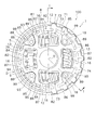
図1はモータサイクル用クラッチ装置100の概略断面図である。図2はクラッチ装置100の概略平面図である。図1は図2のI-I断面図である。図2ではクラッチ機構Cは省略している。図1の右方が軸方向外側(軸方向の第1側の一例)、図1の左方が軸方向内側(軸方向の第2側の一例)である。
ダンパー機構Dは、入力ギヤ8(第1回転体の一例)と、中間回転体1(第2回転体の一例)と、2つの第1コイルスプリング12と、2つの第2コイルスプリング13と、4つのゴム部材16と、を有している。
入力ギヤ8は、エンジンで発生した動力が入力される概ね環状の部材であり、エンジンのクランクシャフトに固定された駆動ギヤ(図示せず)と噛み合っている。具体的には、入力ギヤ8は、本体部81と、4つの第1当接部87と、リングギヤ88(環状部の一例)と、を有している。入力ギヤ8は、例えば亜鉛ダイキャスト製であり、本体部81、第1当接部87およびリングギヤ88は一体成形されている。
中間回転体1は、入力ギヤ8に対して回転可能に設けられており、ダンパー機構Dの出力側の部材として機能している。具体的には、中間回転体1は、クラッチハウジング7と、クラッチハウジング7に固定されたリティーニングプレート9と、を有している。
クラッチハウジング7およびリティーニングプレート9により、第1コイルスプリング12および第2コイルスプリング13は回転方向に弾性変形可能に支持されている。具体的には、クラッチハウジング7およびリティーニングプレート9により、2つの第1支持部73と、2つの第2支持部74と、が形成されている。
クラッチ機構Cは、出力回転体2と、クラッチ部3と、プレッシャプレート4と、ダイヤフラムスプリング5と、支持プレート6と、を有している。
図1に示す状態(クラッチオン状態)では、ダイヤフラムスプリング5によってプレッシャプレート4が軸方向内側に所定の弾性力で押圧され、クラッチ部3の第1クラッチプレート31および第2クラッチプレート32は出力回転体2とプレッシャプレート4との間に挟み込まれている。この状態では、クランクシャフトからダンパー機構Dを介してクラッチ機構Cに動力が伝達される。より詳細には、入力ギヤ8に入力された動力は、中間回転体1を介して第1クラッチプレート31に伝達され、さらに第2クラッチプレート32および出力回転体2を介して、トランスミッションの入力シャフト17に伝達される。このとき、第1当接部87は第2当接部93と当接しており、ストッパ機構Sを介して動力が伝達される。
クラッチ装置100の特徴を以下にまとめる。
このクラッチ装置100では、第1当接部87が第1コイルスプリング12の半径方向外側に配置されているため、第1当接部87が第2当接部93と当接するまでの入力ギヤ8および中間回転体1間の相対回転角度を従来よりも大きく設定できる。つまり、このクラッチ装置100では、ダンパー機構Dの捩り角度を従来よりも大きく設定することが可能となり、設計の自由度を高めることができる。
このクラッチ装置100では、第1当接部87の回転方向寸法が第1開口84の回転方向寸法よりも小さいため、第1当接部87が第2当接部93と当接するための入力ギヤ8および中間回転体1間の相対回転角度をさらに大きく設定できる。
このクラッチ装置100では、複数の第1当接部87がリングギヤ88により連結されているため、リングギヤ88がない場合に比べて、第1当接部87の周辺部の強度を高めることができる。これにより、入力ギヤ8の板厚を薄くしたりでき、クラッチ装置100の軽量化が可能となる。
このクラッチ装置100では、第1開口84に加えて、第2当接部93が配置された第2開口85が入力ギヤ8に形成されているため、入力ギヤ8の開口率が高くなる。これにより、クラッチ装置100のさらなる軽量化が可能となる。
このクラッチ装置100では、第2当接部93が長孔86内に配置されているため、入力ギヤ8の強度を確保しつつ入力ギヤ8および中間回転体1間の相対回転角度を大きく確保できる。
このクラッチ装置100では、第1コイルスプリング12がクラッチハウジング7およびリティーニングプレート9により回転方向に弾性変形可能なように支持されているため、第1コイルスプリング12を支持する構成を簡素な構造で実現できる。
このクラッチ装置100では、第2当接部93がリティーニングプレート本体94の外周部から軸方向に延びているため、リティーニングプレート9の外径寸法を最小限に抑えつつ第2当接部93の半径方向位置を外側に設定することができる。これにより、入力ギヤ8および中間回転体1間の相対回転角度を大きく確保しつつ、クラッチ装置100の軽量化を実現できる。
このクラッチ装置100では、リティーニングプレート9が固定されているハウジング本体71の外周部から連結部72が軸方向に延びているため、中間回転体1全体の強度を高めることができる。このため、クラッチハウジング7の板厚を薄くすることができ、クラッチ装置100の軽量化を実現できる。
このクラッチ装置100では、クラッチハウジング7が板金製であるため、クラッチハウジング7の軽量化が可能となり、装置全体の軽量化を実現できる。
このクラッチ装置100では、第1コイルスプリング12が圧縮された後に第2コイルスプリング13の圧縮が開始されるため、第1コイルスプリング12および第2コイルスプリング13により多段特性を有するダンパー機構Dを実現できる。これにより、モータサイクルの特性に応じてダンパー機構Dの捩り特性を調整することができ、クラッチ装置100の振動減衰性能を高めることができる。
本発明の具体的構成は、前述の実施形態に限定されず、本発明の趣旨を逸脱しない範囲で種々の変形および修正が可能である。
クラッチ機構Cの構成は前述の実施形態に限定されない。例えば、プル式だけでなくプッシュ式のクラッチ装置にも本発明は適用可能である。
前述の実施形態では、入力ギヤ8が入力側部材に連結されているが、出力回転体2が入力側部材に連結されていてもよい。
前述の実施形態では、ダンパー機構Dの捩り特性が3段特性であるが、ダンパー機構Dの捩り特性は3段特性に限定されない。
Claims (10)
- レリーズ機構の作動により入力側部材から出力側部材への動力伝達を遮断するモータサイクル用クラッチ装置であって、
前記入力側部材および出力側部材のうち一方に連結された部材であって、複数の第1当接部を有する第1回転体と、
前記第1回転体に対して回転可能なように配置された部材であって、前記第1当接部と回転方向に当接可能なように隣り合う前記第1当接部の回転方向間に配置された第2当接部を有する第2回転体と、
前記第1当接部の半径方向内側に配置され、前記第1回転体を前記第2回転体と回転方向に弾性的に連結するための第1コイルスプリングと、
前記第1回転体から前記入力側部材および出力側部材のうち他方への動力伝達を遮断するクラッチ機構と、
を備えたモータサイクル用クラッチ装置。 - 前記第1回転体は、前記第1当接部の半径方向内側に配置され前記第1コイルスプリングを収容する第1開口を有しており、
前記第1当接部の回転方向寸法は、前記第1開口の回転方向寸法よりも小さい、
請求項1に記載のモータサイクル用クラッチ装置。 - 前記第1回転体は、前記第1開口を有する本体部と、前記本体部から半径方向外側に延びる前記複数の第1当接部と、前記複数の第1当接部の半径方向外側に配置され前記複数の第1当接部を連結する環状部と、を有している、
請求項1または2に記載のモータサイクル用クラッチ装置。 - 前記第1回転体は、前記本体部、前記第1当接部および前記環状部により形成された第2開口を有しており、
前記第2当接部は、前記第2開口内に配置されている、
請求項3に記載のモータサイクル用クラッチ装置。 - 前記第2開口は、隣り合う前記第1当接部の回転方向間に形成され回転方向に延びる長孔を有しており、
前記第2当接部は、前記長孔内に配置されている、
請求項4に記載のモータサイクル用クラッチ装置。 - 前記第2回転体は、前記第1回転体の軸方向の第1側に配置され前記クラッチ機構に連結されたクラッチハウジングと、前記第1回転体の軸方向の第2側に配置された部材であって前記クラッチハウジングに固定され前記第2当接部を有するリティーニングプレートと、を有しており、
前記第1コイルスプリングは、前記クラッチハウジングおよびリティーニングプレートにより回転方向に弾性変形可能なように支持されている、
請求項1から5のいずれかに記載のモータサイクル用クラッチ装置。 - 前記リティーニングプレートは、リティーニングプレート本体と、前記リティーニングプレート本体の外周部から軸方向に延びる前記第2当接部と、前記第2当接部の端部から半径方向内側に延び前記クラッチハウジングに固定された固定部と、を有している、
請求項6に記載のモータサイクル用クラッチ装置。 - 前記クラッチハウジングは、前記リティーニングプレートが固定されたハウジング本体と、前記ハウジング本体の外周部から軸方向に延び前記クラッチ機構に連結された連結部と、を有している、
請求項6または7に記載のモータサイクル用クラッチ装置。 - 前記クラッチハウジングは、板金製である、
請求項6から8のいずれかに記載のモータサイクル用クラッチ装置。 - 前記第1回転体を前記第2回転体に回転方向に弾性的に連結するための部材であって、前記第1および第2回転体の相対回転により前記第1コイルスプリングの圧縮が開始された後に、前記第1および第2回転体の間で圧縮されるように設けられた第2コイルスプリングをさらに備えた、
請求項1から9のいずれかに記載のモータサイクル用クラッチ装置。
Priority Applications (1)
| Application Number | Priority Date | Filing Date | Title |
|---|---|---|---|
| CN2009801222196A CN102057175A (zh) | 2008-06-11 | 2009-04-10 | 摩托车用离合器装置 |
Applications Claiming Priority (2)
| Application Number | Priority Date | Filing Date | Title |
|---|---|---|---|
| JP2008-153560 | 2008-06-11 | ||
| JP2008153560A JP4476342B2 (ja) | 2008-06-11 | 2008-06-11 | モータサイクル用クラッチ装置 |
Publications (1)
| Publication Number | Publication Date |
|---|---|
| WO2009150892A1 true WO2009150892A1 (ja) | 2009-12-17 |
Family
ID=41416603
Family Applications (1)
| Application Number | Title | Priority Date | Filing Date |
|---|---|---|---|
| PCT/JP2009/057375 Ceased WO2009150892A1 (ja) | 2008-06-11 | 2009-04-10 | モータサイクル用クラッチ装置 |
Country Status (3)
| Country | Link |
|---|---|
| JP (1) | JP4476342B2 (ja) |
| CN (1) | CN102057175A (ja) |
| WO (1) | WO2009150892A1 (ja) |
Cited By (1)
| Publication number | Priority date | Publication date | Assignee | Title |
|---|---|---|---|---|
| EP2574822A3 (en) * | 2011-09-29 | 2017-12-27 | Aisin Seiki Kabushiki Kaisha | Torque fluctuation absorber |
Families Citing this family (1)
| Publication number | Priority date | Publication date | Assignee | Title |
|---|---|---|---|---|
| CN115917205B (zh) * | 2020-09-17 | 2026-03-17 | 舍弗勒投资(中国)有限公司 | 双离合器用固定件、双离合器及变速器的组装方法 |
Citations (5)
| Publication number | Priority date | Publication date | Assignee | Title |
|---|---|---|---|---|
| JPH0349430U (ja) * | 1989-09-22 | 1991-05-14 | ||
| JPH0378136U (ja) * | 1989-12-01 | 1991-08-07 | ||
| JPH0849731A (ja) * | 1994-08-05 | 1996-02-20 | Exedy Corp | クラッチ装置 |
| JP2002323065A (ja) * | 2001-04-23 | 2002-11-08 | F C C:Kk | クラッチ |
| JP2003074636A (ja) * | 2001-08-31 | 2003-03-12 | Exedy Corp | ダンパー機構 |
-
2008
- 2008-06-11 JP JP2008153560A patent/JP4476342B2/ja not_active Expired - Fee Related
-
2009
- 2009-04-10 WO PCT/JP2009/057375 patent/WO2009150892A1/ja not_active Ceased
- 2009-04-10 CN CN2009801222196A patent/CN102057175A/zh active Pending
Patent Citations (5)
| Publication number | Priority date | Publication date | Assignee | Title |
|---|---|---|---|---|
| JPH0349430U (ja) * | 1989-09-22 | 1991-05-14 | ||
| JPH0378136U (ja) * | 1989-12-01 | 1991-08-07 | ||
| JPH0849731A (ja) * | 1994-08-05 | 1996-02-20 | Exedy Corp | クラッチ装置 |
| JP2002323065A (ja) * | 2001-04-23 | 2002-11-08 | F C C:Kk | クラッチ |
| JP2003074636A (ja) * | 2001-08-31 | 2003-03-12 | Exedy Corp | ダンパー機構 |
Cited By (1)
| Publication number | Priority date | Publication date | Assignee | Title |
|---|---|---|---|---|
| EP2574822A3 (en) * | 2011-09-29 | 2017-12-27 | Aisin Seiki Kabushiki Kaisha | Torque fluctuation absorber |
Also Published As
| Publication number | Publication date |
|---|---|
| JP4476342B2 (ja) | 2010-06-09 |
| CN102057175A (zh) | 2011-05-11 |
| JP2009299747A (ja) | 2009-12-24 |
Similar Documents
| Publication | Publication Date | Title |
|---|---|---|
| JP5223999B2 (ja) | 捩り振動減衰装置 | |
| WO2011024639A1 (ja) | トルクリミッタ装置 | |
| JP5527428B2 (ja) | 捩り振動減衰装置 | |
| JP5565473B2 (ja) | 捩り振動減衰装置 | |
| WO2014185182A1 (ja) | モータサイクル用クラッチ装置 | |
| JP4385045B2 (ja) | ダンパー機構 | |
| JP4495936B2 (ja) | クラッチディスク組立体 | |
| JP5772983B2 (ja) | 捩り振動減衰装置 | |
| JP2009115262A (ja) | フライホイール | |
| JP4476342B2 (ja) | モータサイクル用クラッチ装置 | |
| JP4975723B2 (ja) | モータサイクル用クラッチ装置 | |
| JP2020169683A (ja) | トルクリミッタ付きダンパ装置 | |
| CN104204604A (zh) | 扭转振动衰减装置 | |
| JP4256909B2 (ja) | クラッチ装置 | |
| JP2015081623A (ja) | 車両用ダンパ装置 | |
| JP5525435B2 (ja) | トルクリミッタ付き軸継手 | |
| JP3894454B2 (ja) | モータサイクル用クラッチ装置 | |
| JP4520961B2 (ja) | モータサイクル用クラッチ装置 | |
| JP2006170400A (ja) | モータサイクル用クラッチ装置 | |
| KR100778910B1 (ko) | 자동차용 클러치 디스크 | |
| KR101542944B1 (ko) | 이중 질량체 플라이휠 | |
| JP2013108570A (ja) | 捩り振動減衰装置 | |
| WO2014108951A1 (ja) | 捩り振動低減装置 | |
| JP2013015188A (ja) | 捩り振動減衰装置 | |
| JP2014126097A (ja) | 捩り振動低減装置 |
Legal Events
| Date | Code | Title | Description |
|---|---|---|---|
| WWE | Wipo information: entry into national phase |
Ref document number: 200980122219.6 Country of ref document: CN |
|
| 121 | Ep: the epo has been informed by wipo that ep was designated in this application |
Ref document number: 09762323 Country of ref document: EP Kind code of ref document: A1 |
|
| NENP | Non-entry into the national phase |
Ref country code: DE |
|
| WWE | Wipo information: entry into national phase |
Ref document number: 58/CHENP/2011 Country of ref document: IN |
|
| 122 | Ep: pct application non-entry in european phase |
Ref document number: 09762323 Country of ref document: EP Kind code of ref document: A1 |