WO2009145115A1 - フィンチューブ型熱交換器 - Google Patents
フィンチューブ型熱交換器 Download PDFInfo
- Publication number
- WO2009145115A1 WO2009145115A1 PCT/JP2009/059398 JP2009059398W WO2009145115A1 WO 2009145115 A1 WO2009145115 A1 WO 2009145115A1 JP 2009059398 W JP2009059398 W JP 2009059398W WO 2009145115 A1 WO2009145115 A1 WO 2009145115A1
- Authority
- WO
- WIPO (PCT)
- Prior art keywords
- heat transfer
- cut
- raised portions
- raised
- main cut
- Prior art date
- Legal status (The legal status is an assumption and is not a legal conclusion. Google has not performed a legal analysis and makes no representation as to the accuracy of the status listed.)
- Ceased
Links
Images




Classifications
-
- F—MECHANICAL ENGINEERING; LIGHTING; HEATING; WEAPONS; BLASTING
- F28—HEAT EXCHANGE IN GENERAL
- F28F—DETAILS OF HEAT-EXCHANGE AND HEAT-TRANSFER APPARATUS, OF GENERAL APPLICATION
- F28F1/00—Tubular elements; Assemblies of tubular elements
- F28F1/10—Tubular elements and assemblies thereof with means for increasing heat-transfer area, e.g. with fins, with projections, with recesses
- F28F1/12—Tubular elements and assemblies thereof with means for increasing heat-transfer area, e.g. with fins, with projections, with recesses the means being only outside the tubular element
- F28F1/24—Tubular elements and assemblies thereof with means for increasing heat-transfer area, e.g. with fins, with projections, with recesses the means being only outside the tubular element and extending transversely
- F28F1/32—Tubular elements and assemblies thereof with means for increasing heat-transfer area, e.g. with fins, with projections, with recesses the means being only outside the tubular element and extending transversely the means having portions engaging further tubular elements
- F28F1/325—Fins with openings
Definitions
- the present invention relates to a finned-tube heat exchanger, in particular, a plurality of heat transfer fins arranged in the airflow with a gap in the plate thickness direction, and inserted in the plurality of heat transfer fins in the airflow direction.
- a plurality of heat transfer tubes arranged in a substantially orthogonal direction, and a plurality of cut-and-raised portions arranged from the upstream side to the downstream side in the airflow direction on both sides in the vertical direction of the heat transfer tubes on the heat transfer fin surface
- the present invention relates to a finned tube heat exchanger formed by cutting and raising.
- the dead water area formed in the downstream portion of the heat transfer fin 102 in the air flow direction of the heat transfer tube 103 is reduced.
- the air flow in the vicinity of the heat transfer tubes 103 is changed to the air flow in the heat transfer tubes 103 on both sides in the vertical direction of the heat transfer tubes 103 on the surface of the heat transfer fins.
- Cut-and-raised portions 104a to 104c and 104d to 104f that are inclined with respect to the flow direction of the air flow are formed by the cut-and-raise processing so as to guide to the rear side of the direction, and further heat exchange between air and a heat medium such as a refrigerant
- the cut-raised portions 104a to 104c 104d to 104f are divided into three parts from the upstream side to the downstream side in the air flow direction and arranged on a straight line (see straight line L in FIG. 1) (Japanese Patent Laid-Open No. 2008-111646 as Patent Document 1). No. publication). reference).
- An object of the present invention is to arrange a plurality of heat transfer fins arranged in the airflow side by side with an interval in the plate thickness direction, and to be inserted in the plurality of heat transfer fins and in a direction substantially orthogonal to the flow direction of the airflow.
- a plurality of cut-and-raised parts arranged from the upstream side to the downstream side in the air flow direction are formed by cutting and raising on both sides of the heat transfer pipe in the vertical direction of the heat transfer pipe.
- the fin tube type heat exchanger the drainage property between the cut and raised portions is ensured, and the heat transfer promoting effect at each cut and raised portion is sufficiently exhibited.
- the finned tube heat exchanger includes a plurality of heat transfer fins and a plurality of heat transfer tubes.
- the heat transfer fins are arranged in the airflow side by side with a space in the thickness direction.
- the heat transfer tubes are inserted into the plurality of heat transfer fins, and are arranged in a direction substantially orthogonal to the airflow direction.
- a plurality of main cut and raised portions arranged from the upstream side to the downstream side in the air flow direction are formed by cutting and raising processing.
- the main cut and raised portion is inclined with respect to the flow direction of the air flow so that the air flow in the vicinity of the heat transfer tube is guided to the rear side in the flow direction of the air flow of the heat transfer tube, and the plurality of main cut and raised portions of the heat transfer fins
- an auxiliary cut-and-raised part is further formed by a cut-and-raised process at a position far from the heat transfer tube.
- a plurality of main cut and raised portions arranged from the upstream side to the downstream side in the airflow direction are guided so that the airflow in the vicinity of the heat transfer tube is guided to the rear side in the airflow direction of the heat transfer tube.
- the portion of the heat transfer fin on the downstream side in the flow direction of the airflow in the heat transfer fin is arranged to be inclined with respect to the flow direction of the airflow, the portion of the heat transfer fin on the downstream side in the flow direction of the airflow in the heat transfer fin, as in the case where a plurality of conventional cut-and-raised portions are arranged in a straight line It is possible to obtain a heat transfer promoting effect by reducing the dead water area formed in the heat sink and renewing the boundary layer in the heat transfer fin.
- each main cut and raised part Since the number of cut-and-raised parts can be increased without making the gap between them as small as possible, it is possible to secure a gap between the main cut-and-raised parts compared to the conventional arrangement of multiple raised and raised parts on a straight line. Thus, even when the number of cut-and-raised portions is increased while reducing the angle of attack, drainage between the cut-and-raised portions can be ensured.
- the auxiliary cut-and-raised part is arranged at a position farther from the heat transfer tube than the plurality of main cut-and-raised parts of the heat transfer fins, the auxiliary cut and raised part is located in a region sandwiched between the plurality of main cut and raised parts and the heat transfer tube.
- the airflow passing through the main cut-and-raised portion and the airflow passing through the auxiliary cut-and-raised portion are less likely to interfere with each other, thereby increasing the number of cut-and-raised portions while reducing the angle of attack.
- the effect of promoting heat transfer at each cut and raised portion can be sufficiently exhibited.
- the angle of attack is reduced while ensuring the drainage between the cut and raised portions and sufficiently exhibiting the heat transfer promoting effect at each cut and raised portion.
- heat transfer can be promoted by increasing the number of cut and raised portions.
- the finned tube heat exchanger according to a second aspect of the present invention is the finned tube heat exchanger according to the first aspect of the present invention, wherein the plurality of main cut-and-raised portions are front ends or rear ends in the air flow direction of the respective main cut-raised portions.
- the straight lines that virtually connect each other are arranged so as to form an angle larger than the angle of attack with respect to the flow direction of the air flow of each main cut and raised portion.
- the straight line that virtually connects the front ends or the rear ends of the air flow direction of each main cut and raised portion has an angle larger than the angle of attack with respect to the air flow direction of each main cut and raised portion.
- each main cut-and-raised part and the air flow direction front end of the main cut-and-raised part downstream are the front end of each main cut-and-raised part in the air flow direction. Or, since it is arranged in a state shifted from the straight line that virtually connects the rear ends, it is possible to secure a gap between the main cut and raised portions compared to a case where a plurality of main cut and raised portions are arranged on a straight line. This makes it easier to ensure the drainage between the main raised parts.
- each main cut and raised portion and the front end in the air flow direction of the main cut and raised portion on the downstream side virtually connect the front end or rear end of the main cut and raised portions in the air flow direction. Since it is arranged in a state deviated from the connecting straight line, the air flow guided to the downstream side by each main cut-and-raised part is compared to the case where a plurality of main cut-and-raised parts are arranged on a straight line. It becomes difficult to interfere with the airflow that is about to pass through the portion, and the effect of promoting heat transfer in each main cut and raised portion can be more easily exhibited.
- the finned tube heat exchanger according to a third aspect of the present invention is the finned tube heat exchanger according to the second aspect of the present invention, wherein each main cut-and-raised part extends from the heat transfer fin surface toward the downstream side in the air flow direction.
- the height is gradually increasing.
- the shape of each main cut and raised portion is formed so that the height gradually increases toward the downstream side in the air flow direction, thereby generating a vertical vortex behind each main cut and raised portion. Therefore, the heat transfer promotion effect by the main raising part can be further enhanced. And such a vertical vortex grows toward the downstream side of the airflow direction, and brings about a large heat transfer promotion effect.
- the airflow direction of each main cut and raised portion By arranging the rear end and the front end in the air flow direction of the main cut-and-raised part on the downstream side of the main cut-and-raised part in a state shifted from the straight line that virtually connects the front ends or rear ends of the air flow in the main cut-and-raised part Since the growth of the vertical vortex is less likely to be hindered, the effect of promoting heat transfer by the vertical vortex can be reliably obtained.
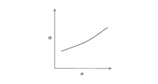
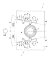
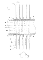
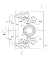
- FIG. 1 It is sectional drawing of the conventional fin tube type heat exchanger. It is a figure which shows the relationship between an angle of attack and exchange heat quantity. It is a figure which shows the relationship between an angle of attack and the amount of exchange heat per ventilation resistance. It is sectional drawing of the fin tube type heat exchanger concerning one Embodiment of this invention. It is II sectional drawing of FIG. It is sectional drawing of the fin tube type heat exchanger concerning the modification 1. FIG. It is sectional drawing of the finned-tube type heat exchanger concerning the modification 2. It is II sectional drawing of FIG. It is sectional drawing of the finned-tube type heat exchanger concerning the modification 2.
- FIG. 4 is a cross-sectional view of the finned tube heat exchanger 1.
- FIG. 5 is a cross-sectional view taken along the line II of FIG. (1)
- the fin tube type heat exchanger 1 is a cross fin and tube type heat exchanger, and mainly includes a plurality of plate-shaped heat transfer fins 2 and a plurality of heat transfer tubes 3. And.
- the heat transfer fins 2 are arranged side by side at a predetermined interval in the plate thickness direction with the plane thereof being generally along the flow direction of the airflow such as air.
- a plurality of through holes 2 a are formed in the heat transfer fins 2 at intervals in a direction substantially orthogonal to the airflow direction.
- a peripheral portion of the through hole 2 a is an annular collar portion 8 that protrudes to one side in the plate thickness direction of the heat transfer fin 2.
- the collar portion 8 is in contact with the surface opposite to the surface on which the collar portion 8 of the heat transfer fin 2 adjacent in the plate thickness direction is formed, and a predetermined interval (hereinafter, referred to as the plate thickness direction of the heat transfer fin 2). This predetermined interval is set as a fin pitch FP).
- the heat transfer tube 3 is a tube member through which a heat medium such as a refrigerant flows.
- the heat transfer tube 3 is inserted into the plurality of heat transfer fins 2 and is disposed in a direction substantially orthogonal to the airflow direction. Specifically, the heat transfer tube 3 passes through the through holes 2 a formed in the heat transfer fins 2, and comes into close contact with the inner surface of the collar portion 8 by tube expansion work when the fin tube heat exchanger 1 is assembled. ing.
- the finned tube heat exchanger 1 of the present embodiment is used in a state where the plurality of heat transfer tubes 3 are arranged so that the arrangement direction of the heat transfer tubes 3 is substantially vertical (that is, FIG. Only one of the heat transfer tubes 3 is shown). For this reason, the airflow flows so as to cross the finned tube heat exchanger 1 in a substantially horizontal direction.
- the arrangement direction of the heat transfer tubes 3 is indicated.
- the heat transfer fins 2 have a plurality of (in this embodiment) arranged from the upstream side to the downstream side in the airflow direction on both sides in the vertical direction of the heat transfer tubes 3 (that is, the lower side and the upper side of the heat transfer tubes 3).
- the three main cut-and-raised portions 4a to 4f on the lower side of the heat transfer tube 3 and three on the upper side of the heat transfer tube 3 are formed on the heat transfer fin surface 2b by the cut-and-raise processing.
- the three main cut and raised portions on the lower side of the heat transfer tube 3 are defined as first main cut and raised portions 4a to 4c, and the three upper cut and raised portions on the heat transfer tube 3 are referred to as second main cut and raised portions 4d to 4f. .
- Each of the main cut and raised portions 4a to 4f is a substantially trapezoidal portion formed by cutting the heat transfer fin 2 and raising it in the direction extending in the plate thickness direction of the heat transfer fin 2. Then, in the portions adjacent to the main cut-and-raised portions 4a to 4f of the heat transfer fin 2, as the main cut-and-raised portions 4a to 4f are cut and raised, the substantially trapezoidal slit holes 7a to 7f are formed. It is formed so as to correspond to the cut and raised portions 4a to 4f.
- first main cut-and-raised portions 4a to 4c and second main cut-and-raised portions 4d to 4f allow the airflow to flow so that the airflow in the vicinity of the heat transfer tube 3 is guided to the rear side in the airflow direction of the heat transfer tube 3. It arrange
- the parts 4a to 4c are arranged in a straight line on the straight line M1 (that is, the angle of attack ⁇ a, the angle of attack ⁇ b, and the angle of attack ⁇ c are the same angle).
- the attack angles ⁇ d to ⁇ f with respect to the air flow direction of the second main cut and raised portions 4d to 4f are positive values
- the second main cut and raised portions 4d to 4f are positive values.
- the attack angles ⁇ a to ⁇ f are such that the front ends 5a to 5f in the air flow direction of the main cut and raised portions 4a to 4f are more heat transfer tubes than the rear ends 6a to 6f of the main cut and raised portions 4a to 4f in the air flow direction. It is assumed that it is a positive value when it is inclined so as to be located on the side far from 3.
- the heat transfer fin 2 includes the first auxiliary cut and raised portion 4g at a position farther from the heat transfer tube 3 than the first main cut and raised portions 4a to 4c, and the second main cut and raised portion.
- a second auxiliary cut-and-raised portion 4h is further formed by the cut-and-raft process at a position farther from the heat transfer tube 3 than the raised portions 4d to 4f. That is, the auxiliary cut-and-raised portions 4g and 4h are arranged so as to avoid the area sandwiched between the main cut-and-raised portions 4a to 4f and the heat transfer tube 3.
- the first auxiliary cut-and-raised portion 4g The second main cut-and-raised portion 4h is arranged on the lower side in the vertical direction of the first main cut-and-raised portion 4b. For this reason, the number of cut-and-raised portions can be increased without reducing the gap between the main cut-and-raised portions as much as possible.
- the airflow passing through the main cut-and-raised portions 4a to 4f and the airflow passing through the auxiliary cut-and-raised portions 4g and 4h are compared with the case where the airflow passes through the main cut-and-raised portions 4a to 4f and the heat transfer tube 3.
- the auxiliary cut-and-raised portions 4g and 4h are formed by cutting the heat transfer fins 2 and raising them in the direction extending in the plate thickness direction of the heat transfer fins 2 in the same manner as the main cut-and-raised portions 4a to 4f. It is a substantially trapezoidal part.
- assistant cut-and-raised part 4g and 4h are cut and raised, and substantially trapezoidal shaped slit holes 7g and 7h are each auxiliary
- the first auxiliary cut-and-raised portion 4g and the second auxiliary cut-and-raised portion 4h are similar to the first main cut and raised portions 4a to 4c and the second main cut and raised portions 4d to 4f.
- the angles of attack ⁇ g and ⁇ h with respect to the flow direction are positive values
- the angle of attack ⁇ g of the first auxiliary cut and raised portion 4g is the angle of attack ⁇ a to the first main cut and raised portions 4a to 4c.
- the angle of attack ⁇ h of the second auxiliary cut-and-raised portion 4h is set to be less than ⁇ c, and is set to be less than the angles of attack ⁇ d to ⁇ f of the second main cut-and-raised portions 4d to 4f. Therefore, the airflow passing through the first main cut and raised portions 4a to 4c and the airflow passing through the first auxiliary cut and raised portion 4g are less likely to interfere with each other, and pass through the second main cut and raised portions 4d to 4f. The airflow and the airflow passing through the second auxiliary cut and raised portion 4h are further less likely to interfere with each other.
- the heights of the main cut-and-raised portions 4a to 4f and the auxiliary cut-and-raised portions 4g and 4h from the heat transfer fin surface 2b gradually increase toward the downstream side in the airflow direction. More specifically, with respect to the first main cut and raised portion 4a, the height from the heat transfer fin surface 2b of the rear end 6a is higher than the height from the heat transfer fin surface 2b of the front end 5a.
- the height from the heat transfer fin surface 2b of the rear end 6b is higher than the height from the heat transfer fin surface 2b of the front end 5b
- the first main cut and raised portion 4c The height of the rear end 6c from the heat transfer fin surface 2b is higher than the height of the front end 5c from the heat transfer fin surface 2b
- the second main cut and raised portion 4d has the heat transfer fin surface 2b of the front end 5d.
- the height from the heat transfer fin surface 2b of the rear end 6d is higher than the height from the rear end 6e
- the rear end 6e of the second main cut and raised portion 4e is higher than the height from the heat transfer fin surface 2b of the front end 5e.
- the height from the heat transfer fin surface 2b is high, Regarding the two main cut and raised portions 4f, the height of the rear end 6f from the heat transfer fin surface 2b is higher than the height of the front end 5f from the heat transfer fin surface 2b.
- the height of the rear end 6g from the heat transfer fin surface 2b is higher than the height of the front end 5g from the heat transfer fin surface 2b, and the second auxiliary cut-and-raised portion 4h has a heat transfer fin surface of the front end 5h.
- the height from the heat transfer fin surface 2b of the rear end 6h is higher than the height from 2b.
- a plurality of main cut-and-raised portions 4a to 4f arranged from the upstream side to the downstream side in the airflow direction are heat transfer tubes.
- 3 is arranged so as to be inclined with respect to the flow direction of the air flow so that the air flow in the vicinity of the heat transfer tube 3 is guided to the rear side in the flow direction of the air flow of the heat transfer tube 3.
- the heat transfer enhancement effect by reducing the dead water area formed in the downstream portion of the heat transfer fin 3 in the air flow direction of the heat transfer fin 2, updating the boundary layer in the heat transfer fin 2, etc.
- the auxiliary cut-and-raised portions 4g and 4h are further provided at positions far from the heat transfer tube 3 with respect to the plurality of main cut-and-raised portions 4a to 4f of the heat transfer fin 2.
- the number of cut and raised portions can be increased without minimizing the gap between the main cut and raised portions, and when arranging a plurality of cut and raised portions on a straight line (for example, the first main cut and raised portions) Compared to the case where the number of parts is increased from three to four and arranged straight on the straight line M1, or the second cut-and-raised part is increased from three to four and arranged straight on the straight line M2, each first main When it is easy to secure the gaps C4a, C4b, C4d, C4e between the cut-and-raised portions 4a to 4c and between the second cut-and-raised portions 4d to 4f, and when increasing the number of cut-and-raised portions while reducing the angle of attack ( For example, the configuration in which three cut-and-raised portions are formed on the lower side and upper side of the heat transfer tube in FIG.
- the auxiliary cut-and-raised portions 4g and 4h are arranged at positions farther from the heat transfer tube 3 than the plurality of main cut-and-raised portions 4a to 4f of the heat transfer fin 2.
- the airflow passing through the main cut-and-raised portion interferes with the airflow passing through the auxiliary cut-and-raised portion as compared with the case where the airflow passes through the main cut-and-raised portion compared to the case where the airflow passes through the main cut and raised portions 4a to 4f and the heat transfer tube 3.
- the drainage between the cut and raised portions is ensured and the effect of promoting heat transfer in each cut and raised portion is sufficiently exhibited.
- Heat transfer can be promoted by increasing the number of cut and raised portions while reducing the corners.
- the angle of attack ⁇ g of the first auxiliary cut-and-raised portion 4g is set to be less than the angle of attack ⁇ a to ⁇ c of the first main cut-and-raised portion 4a to 4c
- the second The angle of attack ⁇ h of the auxiliary cut-and-raised portion 4h is set to be less than the angle of attack ⁇ d to ⁇ f of the second main cut-and-raised portions 4d to 4f
- the airflow passing through the cut and raised portion 4g is less likely to interfere
- the airflow passing through the second main cut and raised portions 4d to 4f and the airflow passing through the second auxiliary cut and raised portion 4h are further less likely to interfere. Therefore, the heat transfer promoting effect at each cut and raised portion is more easily exhibited.
- each cut-and-raised portion 4a to 4h is formed such that the height from the heat transfer fin surface 2b gradually increases toward the downstream side in the airflow direction.
- a vertical vortex can be generated behind each cut-and-raised portion 4a to 4h, so that the heat transfer promoting effect by the cut-and-raised portions 4a to 4h can be further enhanced.
- the first main cut and raised portions 4a to 4c are arranged in a straight line on the straight line M1, and the second main cut and raised portions 4d to 4h are straight on the straight line M2.
- the arrangement of the first main cut-and-raised portions 4a to 4c and the second main cut-and-raised portions 4d to 4h is devised, and between the first main cut-and-raised portions 4a to 4c and each second cut
- the gaps C4a, C4b, C4d, and C4e between the raised portions 4d to 4f are further increased to further ensure the drainage between the raised portions, and the effect of promoting heat transfer at each main raised portion is further exhibited. It is preferable to make it easy.
- the first main cut and raised portions 14a to 14c are connected to the air currents of the first main cut and raised portions 14a to 14c.
- a straight line that virtually connects the flow direction front ends 15a to 15c in the present modification, a straight line M11
- ⁇ 11 is arranged, and the second main cut and raised portions 14d to 14f are virtually connected to the front ends 15d to 15f in the airflow direction of the second main cut and raised portions 14d to 14f.
- the air flow direction rear ends 16a and 16b of the first main cut and raised portions 4a and 4b and the air flow of the cut and raised portions 14b and 14c on the downstream side thereof are arranged in a state of being deviated from the straight line M11, and the air flow direction rear ends 16d and 16e of the second main cut and raised portions 14d and 14e and the cut and raised portions 14e on the downstream side thereof. Since the front ends 15e and 15f of the air flow direction 14f are displaced from the straight line M12, the first cut and raised portions are arranged in a straight line as in the above-described embodiment.
- the fin tube type heat exchanger 1 of this modification while being able to obtain the same operation effect as the above-mentioned embodiment, when arranging the main raising part on a straight line like the above-mentioned embodiment, In comparison, the drainage between the main cut and raised portions can be further ensured, and the effect of promoting heat transfer in each main cut and raised portion can be more easily exhibited.
- the main cut and raised portions 14a to 14f gradually increase in height from the heat transfer fin surface 12b toward the downstream side in the airflow direction.
- a vertical vortex is generated behind each of the main raised portions 14a to 14f to further enhance the heat transfer promotion effect. Because it grows toward the downstream side in the air flow direction, it brings about a large heat transfer enhancement effect. In order to reliably obtain the heat transfer enhancement effect, the growth of this vertical vortex is hardly hindered. In this sense, in a configuration in which a plurality of main cut-and-raised portions are aligned in a straight line as in the above-described embodiment, the growth of the vertical vortex is somewhat hindered.
- the air flow direction rear ends 16a, 16b of the first main cut-and-raised portions 14a, 14b and the cut-raised portions 14b on the downstream side thereof, 14c is arranged in a state where the air flow front ends 15b and 15c of the air flow 14c are displaced from the straight line M11, and the air flow rear ends 16d and 16e of the second main cut and raised portions 14d and 14e and the downstream cuts thereof.
- the vertical direction vortex growth is less likely to be hindered by arranging the raising portions 14e and 14f in a state where the air flow direction front ends 15e and 15f of the raising portions 14e and 14f are deviated from the straight line M12, the heat transfer promotion effect by the vertical vortex is ensured Can get to.
- the air flow direction front ends 15a to 15c of the first main cut and raised portions 14a to 14c are virtually connected to each other, and the air flow front ends 15d of the second main cut and raised portions 14d to 14f.
- a straight line that virtually connects 15 f to 15 f is an angle of attack ⁇ 1 a to ⁇ 1 c with respect to the air flow direction of each of the first main cut-and-raised portions 14 a to 14 c and an angle of arrival with respect to the air flow direction of each of the second main cut-and-raised portions 14 d to 14 f.
- the air flow direction rear ends 16a, 16b of the first main cut-and-raised portions 14a, 14b and the air-flow of the cut-raised portions 14b, 14c on the downstream side thereof can be obtained.
- the flow direction front ends 15b and 15c are arranged in a state shifted from the straight line M11, and the air flow direction rear ends 16d and 16e of the second main cut and raised portions 14d and 14e and
- the air flow direction front ends 15e and 15f of the flow side cut-and-raised parts 14e and 14f are arranged so as to be deviated from the straight line M12, but the air flow of each of the first main cut and raised parts 14a to 14c.
- a straight line that virtually connects the rear ends 16a to 16c in the direction and a straight line that virtually connects the rear ends 16d to 16f in the flow direction of the second main cut and raised portions 14d to 14f are the first main cut and raised portions.
- the angles of attack ⁇ 1a to ⁇ 1c with respect to the airflow direction of 14a to 14c and the angles of attack ⁇ 1d to ⁇ 1f with respect to the airflow direction of the second main cut and raised portions 14d to 14f may be larger.
- a flat fin is employed as the heat transfer fin, but the present invention is not limited to this, and a waffle heat transfer fin may be employed.
- the heat transfer fins 22 having folds 29a to 29c parallel to the vertical direction are adopted as the heat transfer fins, and each heat transfer tube is used. 3 in the vertical direction, the three first main raised portions 24a to 24c arranged from the upstream side to the downstream side in the airflow direction are cut and raised to the front end in the airflow direction of the heat transfer fins 22.
- the first auxiliary cut-and-raised portion 24g and the second auxiliary cut-and-raised portion 24h are formed on the heat transfer fin surface 22d on which the first main cut-and-raised portion 24b and the second main cut-and-raised portion 24e are formed.
- the heat transfer fin surface 22f is formed with no cut-and-raised portion.
- symbol of the 1-digit number in the above-mentioned embodiment is replaced with the 20th order, and about the angle of attack, "2" is set to the code
- the subscripts are replaced with those added as subscripts, and description of each part of the heat transfer fins 22 other than the folds 29a to 29c and the heat transfer fin surfaces 22c to 22f is omitted.
- the three first main cut-and-raised parts 34a to 34c arranged from the upstream side to the downstream side in the airflow direction are cut and raised to the front end of the heat transfer fin 32 in the airflow direction and Heat transfer fin surface 32c between the downstream fold 39a, heat transfer fin surface 32d between the fold 39a and the downstream fold 39b, and heat transfer between the fold 39b and the downstream fold 39c.
- Three second main raised portions 34d to 34f formed on the fin surface 32e and arranged from the upstream side to the downstream side in the air flow direction on the upper side in the vertical direction of each heat transfer tube 3 are connected to the heat transfer process. It may be formed on the emission surface 32c ⁇ 32e.
- the fold lines 39a to 39c are mountain folds, and the fold line 39b is a valley fold.
- the first auxiliary cut-and-raised portion 34g and the second auxiliary cut-and-raised portion 34h are formed on the heat transfer fin surface 32d on which the first main cut-and-raised portion 34b and the second main cut-and-raised portion 34e are formed. It is formed, and the cut-and-raised part is not formed on the heat transfer fin surface 32f.
- the present invention includes a plurality of heat transfer fins arranged in the airflow side by side at intervals in the plate thickness direction, and a plurality of heat transfer fins inserted in the plurality of heat transfer fins and arranged in a direction substantially orthogonal to the flow direction of the airflow.
- a plurality of cut-and-raised portions arranged from the upstream side to the downstream side in the air flow direction on both sides of the heat transfer tube in the vertical direction of the heat transfer tube. Widely applicable to tube heat exchangers.
Landscapes
- Physics & Mathematics (AREA)
- Engineering & Computer Science (AREA)
- Geometry (AREA)
- Thermal Sciences (AREA)
- Mechanical Engineering (AREA)
- General Engineering & Computer Science (AREA)
- Heat-Exchange Devices With Radiators And Conduit Assemblies (AREA)
Abstract
フィンチューブ型熱交換器(1)は、板厚方向に間隔を空けて並べて気流中に配置される複数の伝熱フィン(2)と、複数の伝熱フィン(2)に挿入されており気流の流れ方向に略直交する方向に配置される複数の伝熱管(3)とを備えている。各伝熱フィン(2)には、伝熱管(3)の鉛直方向における両側において、気流の流れ方向上流側から下流側に向かって並ぶ複数の主切り起こし部が形成されており、伝熱フィン(2)の複数の主切り起こし部に対して伝熱管(3)から遠い側の位置には、補助切り起こし部が、切り起こし加工によりさらに形成されている。
Description
本発明は、フィンチューブ型熱交換器、特に、板厚方向に間隔を空けて並べて気流中に配置される複数の伝熱フィンと、複数の伝熱フィンに挿入されており気流の流れ方向に略直交する方向に配置される複数の伝熱管とを備えており、伝熱フィン面の伝熱管の鉛直方向における両側において、気流の流れ方向上流側から下流側に向かって並ぶ複数の切り起こし部が切り起こし加工により形成されたフィンチューブ型熱交換器に関する。
空気調和装置等に使用されるフィンチューブ型熱交換器として、図1に示されるように、伝熱フィン102における伝熱管103の空気流の流れ方向下流側の部分に形成される死水域の低減や伝熱フィン102における境界層の更新等による伝熱促進のために、伝熱フィン面の伝熱管103の鉛直方向における両側において、伝熱管103近傍の空気流を伝熱管103の空気流の流れ方向後側に案内するように、空気流の流れ方向に対して傾斜した切り起こし部104a~104c、104d~104fが切り起こし加工により形成され、さらに、空気と冷媒等の熱媒体との熱交換より発生したドレン水が切り起こし部104a~104c、104d~104fに滞留して排水性が低下するのを防ぐために、切り起こし部104a~104c、104d~104fを空気流の流れ方向上流側から下流側に向かって3つに分割して一直線(図1の直線L参照)上に並べたものがある(特許文献1としての特開2008-111646号公報参照)。
参照)。
参照)。
ところで、上述の切り起こし部の空気流の流れ方向に対する迎え角α(図1参照)を小さくすると、切り起こし部1個当たりの伝熱促進効果は低下する傾向にあるが(図2における迎え角αと交換熱量Qとの関係を参照)、通風抵抗ΔP当たりの伝熱促進効果は大きくなる傾向にある(図3における迎え角αと通風抵抗当たりの交換熱量Q/ΔPとの関係を参照)。
このため、上述のような、伝熱フィン面の伝熱管の鉛直方向における両側において、空気流の流れ方向上流側から下流側に向かって一直線上に並ぶ複数の切り起こし部が切り起こし加工により形成されたフィンチューブ型熱交換器においては、迎え角を小さくしつつ切り起こし部の数を増やすことで、理論的には、さらなる伝熱促進を図ることが可能になる。
このため、上述のような、伝熱フィン面の伝熱管の鉛直方向における両側において、空気流の流れ方向上流側から下流側に向かって一直線上に並ぶ複数の切り起こし部が切り起こし加工により形成されたフィンチューブ型熱交換器においては、迎え角を小さくしつつ切り起こし部の数を増やすことで、理論的には、さらなる伝熱促進を図ることが可能になる。
しかし、迎え角を小さくしつつ切り起こし部の数を増やすと、切り起こし部間の間隔が小さくなり、ドレン水が切り起こし部間の隙間にブリッジ状に滞留しやすくなり、排水性が確保できなくなるおそれがある。また、切り起こし部間の間隔が小さい状態で複数の切り起こし部を一直線上に並べると、各切り起こし部によって下流側に導かれる空気流が、その下流側の切り起こし部を通過しようとする空気流に干渉しやすくなり、各切り起こし部における伝熱促進効果が十分に発揮されなくなるおそれがある。
このため、迎え角を小さくしつつ切り起こし部の数を増やすことで伝熱促進を図るためには、切り起こし部間の排水性を確保しつつ、各切り起こし部における伝熱促進効果が十分に発揮されるようにする必要がある。
本発明の課題は、板厚方向に間隔を空けて並べて気流中に配置される複数の伝熱フィンと、複数の伝熱フィンに挿入されており気流の流れ方向に略直交する方向に配置される複数の伝熱管とを備えており、伝熱フィン面の伝熱管の鉛直方向における両側において、気流の流れ方向上流側から下流側に向かって並ぶ複数の切り起こし部が切り起こし加工により形成されたフィンチューブ型熱交換器において、切り起こし部間の排水性を確保し、かつ、各切り起こし部における伝熱促進効果が十分に発揮されるようにすることにある。
このため、迎え角を小さくしつつ切り起こし部の数を増やすことで伝熱促進を図るためには、切り起こし部間の排水性を確保しつつ、各切り起こし部における伝熱促進効果が十分に発揮されるようにする必要がある。
本発明の課題は、板厚方向に間隔を空けて並べて気流中に配置される複数の伝熱フィンと、複数の伝熱フィンに挿入されており気流の流れ方向に略直交する方向に配置される複数の伝熱管とを備えており、伝熱フィン面の伝熱管の鉛直方向における両側において、気流の流れ方向上流側から下流側に向かって並ぶ複数の切り起こし部が切り起こし加工により形成されたフィンチューブ型熱交換器において、切り起こし部間の排水性を確保し、かつ、各切り起こし部における伝熱促進効果が十分に発揮されるようにすることにある。
第1の発明にかかるフィンチューブ型熱交換器は、複数の伝熱フィンと、複数の伝熱管とを備えている。伝熱フィンは、板厚方向に間隔を空けて並べて気流中に配置される。伝熱管は、複数の伝熱フィンに挿入されており、気流の流れ方向に略直交する方向に配置される。そして、各伝熱フィンには、伝熱管の鉛直方向における両側において、気流の流れ方向上流側から下流側に向かって並ぶ複数の主切り起こし部が、切り起こし加工により形成されており、複数の主切り起こし部は、伝熱管近傍の気流が、伝熱管の気流の流れ方向後側に案内されるように気流の流れ方向に対して傾斜しており、伝熱フィンの複数の主切り起こし部に対して伝熱管から遠い側の位置には、補助切り起こし部が、切り起こし加工によりさらに形成されている。
このフィンチューブ型熱交換器では、気流の流れ方向上流側から下流側に向かって並ぶ複数の主切り起こし部が、伝熱管近傍の気流が伝熱管の気流の流れ方向後側に案内されるように気流の流れ方向に対して傾斜するように配置されているため、従来の複数の切り起こし部を一直線上に並べる場合と同様に、伝熱フィンにおける伝熱管の気流の流れ方向下流側の部分に形成される死水域の低減や伝熱フィンにおける境界層の更新等による伝熱促進効果を得ることができる。そして、このフィンチューブ型熱交換器では、伝熱フィンの複数の主切り起こし部に対して伝熱管から遠い側の位置に補助切り起こし部がさらに形成されていることから、各主切り起こし部間の隙間を極力小さくすることなく切り起こし部の数を増加させることができるため、従来の複数の切り起こし部を一直線上に並べる場合に比べて、各主切り起こし部間の隙間を確保しやすくなり、これにより、迎え角を小さくしつつ切り起こし部の数を増やす場合であっても、切り起こし部間の排水性を確保することができる。しかも、補助切り起こし部は伝熱フィンの複数の主切り起こし部に対して伝熱管から遠い側の位置に配置されているため、複数の主切り起こし部と伝熱管とによって挟まれた領域に配置する場合に比べて、主切り起こし部を通過する気流と補助切り起こし部を通過する気流とが干渉しにくくなり、これにより、迎え角を小さくしつつ切り起こし部の数を増やす場合であっても、各切り起こし部における伝熱促進効果が十分に発揮されるようにすることができる。
このフィンチューブ型熱交換器では、気流の流れ方向上流側から下流側に向かって並ぶ複数の主切り起こし部が、伝熱管近傍の気流が伝熱管の気流の流れ方向後側に案内されるように気流の流れ方向に対して傾斜するように配置されているため、従来の複数の切り起こし部を一直線上に並べる場合と同様に、伝熱フィンにおける伝熱管の気流の流れ方向下流側の部分に形成される死水域の低減や伝熱フィンにおける境界層の更新等による伝熱促進効果を得ることができる。そして、このフィンチューブ型熱交換器では、伝熱フィンの複数の主切り起こし部に対して伝熱管から遠い側の位置に補助切り起こし部がさらに形成されていることから、各主切り起こし部間の隙間を極力小さくすることなく切り起こし部の数を増加させることができるため、従来の複数の切り起こし部を一直線上に並べる場合に比べて、各主切り起こし部間の隙間を確保しやすくなり、これにより、迎え角を小さくしつつ切り起こし部の数を増やす場合であっても、切り起こし部間の排水性を確保することができる。しかも、補助切り起こし部は伝熱フィンの複数の主切り起こし部に対して伝熱管から遠い側の位置に配置されているため、複数の主切り起こし部と伝熱管とによって挟まれた領域に配置する場合に比べて、主切り起こし部を通過する気流と補助切り起こし部を通過する気流とが干渉しにくくなり、これにより、迎え角を小さくしつつ切り起こし部の数を増やす場合であっても、各切り起こし部における伝熱促進効果が十分に発揮されるようにすることができる。
このように、このフィンチューブ型熱交換器では、切り起こし部間の排水性を確保し、かつ、各切り起こし部における伝熱促進効果が十分に発揮されるようにしながら、迎え角を小さくしつつ切り起こし部の数を増やすことで伝熱促進を図ることができる。
第2の発明にかかるフィンチューブ型熱交換器は、第1の発明にかかるフィンチューブ型熱交換器において、複数の主切り起こし部は、各主切り起こし部の気流の流れ方向前端又は後端同士を仮想的に結ぶ直線が、各主切り起こし部の気流の流れ方向に対する迎え角よりも大きな角度をなすように、配置されている。
このフィンチューブ型熱交換器では、各主切り起こし部の気流の流れ方向前端同士又は後端同士を仮想的に結ぶ直線が各主切り起こし部の気流の流れ方向に対する迎え角よりも大きな角度をなすように配置されていることから、各主切り起こし部の気流の流れ方向後端とその下流側の主切り起こし部の気流の流れ方向前端とが各主切り起こし部の気流の流れ方向前端又は後端同士を仮想的に結ぶ直線からずれた状態で配置されることになるため、複数の主切り起こし部を一直線上に並べる場合に比べて、各主切り起こし部間の隙間を確保しやすくなり、主切り起こし部間の排水性をさらに確保しやすくできる。しかも、各主切り起こし部の気流の流れ方向後端とその下流側の主切り起こし部の気流の流れ方向前端とが各主切り起こし部の気流の流れ方向前端又は後端同士を仮想的に結ぶ直線からずれた状態で配置されているため、複数の主切り起こし部を一直線上に並べる場合に比べて、各主切り起こし部によって下流側に導かれる気流が、その下流側の主切り起こし部を通過しようとする気流に干渉しにくくなり、各主切り起こし部における伝熱促進効果がさらに発揮されやすくすることができる。
このフィンチューブ型熱交換器では、各主切り起こし部の気流の流れ方向前端同士又は後端同士を仮想的に結ぶ直線が各主切り起こし部の気流の流れ方向に対する迎え角よりも大きな角度をなすように配置されていることから、各主切り起こし部の気流の流れ方向後端とその下流側の主切り起こし部の気流の流れ方向前端とが各主切り起こし部の気流の流れ方向前端又は後端同士を仮想的に結ぶ直線からずれた状態で配置されることになるため、複数の主切り起こし部を一直線上に並べる場合に比べて、各主切り起こし部間の隙間を確保しやすくなり、主切り起こし部間の排水性をさらに確保しやすくできる。しかも、各主切り起こし部の気流の流れ方向後端とその下流側の主切り起こし部の気流の流れ方向前端とが各主切り起こし部の気流の流れ方向前端又は後端同士を仮想的に結ぶ直線からずれた状態で配置されているため、複数の主切り起こし部を一直線上に並べる場合に比べて、各主切り起こし部によって下流側に導かれる気流が、その下流側の主切り起こし部を通過しようとする気流に干渉しにくくなり、各主切り起こし部における伝熱促進効果がさらに発揮されやすくすることができる。
第3の発明にかかるフィンチューブ型熱交換器は、第2の発明にかかるフィンチューブ型熱交換器において、各主切り起こし部は、気流の流れ方向下流側に向かって伝熱フィン面からの高さが漸増している。
このフィンチューブ型熱交換器では、各主切り起こし部の形状を気流の流れ方向下流側に向かって高さが漸増した形状にすることによって、各主切り起こし部の背後に縦渦を生じさせることができるため、主切り起こし部による伝熱促進効果をさらに高めることができるようになっている。
そして、このような縦渦は、気流の流れ方向下流側に向かって成長することで、大きな伝熱促進効果をもたらすものであるが、上述のように、各主切り起こし部の気流の流れ方向後端とその下流側の主切り起こし部の気流の流れ方向前端とが各主切り起こし部の気流の流れ方向前端又は後端同士を仮想的に結ぶ直線からずれた状態で配置されることによって、この縦渦の成長が妨げられにくくなるため、縦渦による伝熱促進効果を確実に得ることができる。
このフィンチューブ型熱交換器では、各主切り起こし部の形状を気流の流れ方向下流側に向かって高さが漸増した形状にすることによって、各主切り起こし部の背後に縦渦を生じさせることができるため、主切り起こし部による伝熱促進効果をさらに高めることができるようになっている。
そして、このような縦渦は、気流の流れ方向下流側に向かって成長することで、大きな伝熱促進効果をもたらすものであるが、上述のように、各主切り起こし部の気流の流れ方向後端とその下流側の主切り起こし部の気流の流れ方向前端とが各主切り起こし部の気流の流れ方向前端又は後端同士を仮想的に結ぶ直線からずれた状態で配置されることによって、この縦渦の成長が妨げられにくくなるため、縦渦による伝熱促進効果を確実に得ることができる。
以下、本発明にかかるフィンチューブ型熱交換器の実施形態について、図面に基づいて説明する。
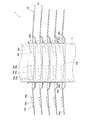
図4、図5に本発明の一実施形態にかかるフィンチューブ型熱交換器1の要部を示す。ここで、図4は、フィンチューブ型熱交換器1の断面図である。図5は、図4のI-I断面図である。
(1)フィンチューブ型熱交換器の基本構成
フィンチューブ型熱交換器1は、クロスフィンアンドチューブ型熱交換器であり、主として、複数のプレート状の伝熱フィン2と、複数の伝熱管3とを備えている。伝熱フィン2は、その平面を空気等の気流の流れ方向に概ね沿わせた状態で、板厚方向に所定の間隔を空けて並んで配置されている。伝熱フィン2には、気流の流れ方向に略直交する方向に間隔を空けて複数の貫通孔2aが形成されている。貫通孔2aの周囲部分は、伝熱フィン2の板厚方向の一方側に突出する環状のカラー部8となっている。カラー部8は、板厚方向に隣り合う伝熱フィン2のカラー部8が形成された面と反対の面に当接しており、伝熱フィン2の板厚方向間に所定の間隔(以下、この所定の間隔をフィンピッチFPとする)が確保されるようになっている。伝熱管3は、内部に冷媒等の熱媒体が流れる管部材であり、複数の伝熱フィン2に挿入されており、気流の流れ方向に略直交する方向に配置されている。具体的には、伝熱管3は、伝熱フィン2に形成された貫通孔2aを貫通しており、フィンチューブ型熱交換器1の組立時の拡管作業によって、カラー部8の内面に密着している。
図4、図5に本発明の一実施形態にかかるフィンチューブ型熱交換器1の要部を示す。ここで、図4は、フィンチューブ型熱交換器1の断面図である。図5は、図4のI-I断面図である。
(1)フィンチューブ型熱交換器の基本構成
フィンチューブ型熱交換器1は、クロスフィンアンドチューブ型熱交換器であり、主として、複数のプレート状の伝熱フィン2と、複数の伝熱管3とを備えている。伝熱フィン2は、その平面を空気等の気流の流れ方向に概ね沿わせた状態で、板厚方向に所定の間隔を空けて並んで配置されている。伝熱フィン2には、気流の流れ方向に略直交する方向に間隔を空けて複数の貫通孔2aが形成されている。貫通孔2aの周囲部分は、伝熱フィン2の板厚方向の一方側に突出する環状のカラー部8となっている。カラー部8は、板厚方向に隣り合う伝熱フィン2のカラー部8が形成された面と反対の面に当接しており、伝熱フィン2の板厚方向間に所定の間隔(以下、この所定の間隔をフィンピッチFPとする)が確保されるようになっている。伝熱管3は、内部に冷媒等の熱媒体が流れる管部材であり、複数の伝熱フィン2に挿入されており、気流の流れ方向に略直交する方向に配置されている。具体的には、伝熱管3は、伝熱フィン2に形成された貫通孔2aを貫通しており、フィンチューブ型熱交換器1の組立時の拡管作業によって、カラー部8の内面に密着している。
また、本実施形態のフィンチューブ型熱交換器1は、複数の伝熱管3の配列方向が略上下方向となるように設置された状態で使用されるものである(すなわち、図4は、複数の伝熱管3のうちの1つだけを示している)。このため、気流は、フィンチューブ型熱交換器1を、略水平方向に向かって横切るように流れることになる。なお、以下の説明において、「上側」、「上方」や「下側」、「下方」という文言を用いる場合には、伝熱管3の配列方向を示しているものとする。
(2)伝熱フィンの詳細形状
次に、本実施形態のフィンチューブ型熱交換器1に用いられている伝熱フィン2の詳細形状について説明する。
伝熱フィン2には、各伝熱管3の鉛直方向における両側(すなわち、各伝熱管3の下側および上側)において、気流の流れ方向上流側から下流側に向かって並ぶ複数(本実施形態では、伝熱管3の下側に3つ、伝熱管3の上側に3つ)の主切り起こし部4a~4fが、切り起こし加工により、伝熱フィン面2bに形成されている。ここで、伝熱管3の下側の3つの主切り起こし部を第1主切り起こし部4a~4c、伝熱管3の上側の3つの切り起こし部を第2主切り起こし部4d~4fとする。各主切り起こし部4a~4fは、伝熱フィン2に切り込みを入れて伝熱フィン2の板厚方向に延びる方向に起こすことによって形成された略台形形状の部分である。そして、伝熱フィン2の各主切り起こし部4a~4fに隣接する部分には、主切り起こし部4a~4fが切り起こされるのに伴って、略台形形状のスリット孔7a~7fが各主切り起こし部4a~4fに対応するように形成されている。
(2)伝熱フィンの詳細形状
次に、本実施形態のフィンチューブ型熱交換器1に用いられている伝熱フィン2の詳細形状について説明する。
伝熱フィン2には、各伝熱管3の鉛直方向における両側(すなわち、各伝熱管3の下側および上側)において、気流の流れ方向上流側から下流側に向かって並ぶ複数(本実施形態では、伝熱管3の下側に3つ、伝熱管3の上側に3つ)の主切り起こし部4a~4fが、切り起こし加工により、伝熱フィン面2bに形成されている。ここで、伝熱管3の下側の3つの主切り起こし部を第1主切り起こし部4a~4c、伝熱管3の上側の3つの切り起こし部を第2主切り起こし部4d~4fとする。各主切り起こし部4a~4fは、伝熱フィン2に切り込みを入れて伝熱フィン2の板厚方向に延びる方向に起こすことによって形成された略台形形状の部分である。そして、伝熱フィン2の各主切り起こし部4a~4fに隣接する部分には、主切り起こし部4a~4fが切り起こされるのに伴って、略台形形状のスリット孔7a~7fが各主切り起こし部4a~4fに対応するように形成されている。
これらの第1主切り起こし部4a~4c及び第2主切り起こし部4d~4fは、伝熱管3近傍の気流が、伝熱管3の気流の流れ方向後側に案内されるように気流の流れ方向に対して傾斜するように配置されている。より具体的には、第1主切り起こし部4a~4cについては、第1主切り起こし部4a~4cの気流の流れ方向に対する各迎え角αa~αcが正値であり、第1主切り起こし部4a~4cが直線M1上に真っ直ぐ並んで(すなわち、迎え角αaと迎え角αbと迎え角αcとは同じ角度である)、配置されている。また、第2主切り起こし部4d~4fについては、第2主切り起こし部4d~4fの気流の流れ方向に対する各迎え角αd~αfが正値であり、第2主切り起こし部4d~4fが直線M2上に真っ直ぐ並んで(すなわち、迎え角αdと迎え角αeと迎え角αfとは同じ角度である)配置されている。ここで、迎え角αa~αfは、各主切り起こし部4a~4fの気流の流れ方向前端5a~5fが各主切り起こし部4a~4fの気流の流れ方向後端6a~6fよりも伝熱管3から遠い側に位置するように傾斜している場合を正値であるものとする。
また、本実施形態において、伝熱フィン2には、第1主切り起こし部4a~4cに対して伝熱管3から遠い側の位置に第1補助切り起こし部4gが、また、第2主切り起こし部4d~4fに対して伝熱管3から遠い側の位置に第2補助切り起こし部4hが、切り起こし加工によりさらに形成されている。すなわち、補助切り起こし部4g、4hは、主切り起こし部4a~4fと伝熱管3とによって挟まれた領域を避けて配置されており、本実施形態においては、第1補助切り起こし部4gは、第1主切り起こし部4bの鉛直方向下側に配置され、また、第2補助切り起こし部4hは、第2主切り起こし部4eの鉛直方向上側に配置されている。このため、各主切り起こし部間の隙間を極力小さくすることなく切り起こし部の数を増加させることができるようになっている。このため、複数の切り起こし部を一直線上に並べる場合(例えば、第1主切り起こし部を3つから4つに増やして直線M1上に真っ直ぐに並べる場合や第2切り起こし部を3つから4つに増やして直線M2上に真っ直ぐに並べる場合)に比べて、各第1主切り起こし部4a~4c間及び各第2切り起こし部4d~4f間の隙間C4a、C4b、C4d、C4eを確保しやすくなっている。しかも、主切り起こし部4a~4fと伝熱管3とによって挟まれた領域に配置する場合に比べて、主切り起こし部4a~4fを通過する気流と補助切り起こし部4g、4hを通過する気流とが干渉しにくくなっている。尚、各補助切り起こし部4g、4hは、主切り起こし部4a~4fと同様に、伝熱フィン2に切り込みを入れて伝熱フィン2の板厚方向に延びる方向に起こすことによって形成された略台形形状の部分である。そして、伝熱フィン2の各補助切り起こし部4g、4hに隣接する部分には、補助切り起こし部4g、4hが切り起こされるのに伴って、略台形形状のスリット孔7g、7hが各補助切り起こし部4g、4hに対応するように形成されている。
また、本実施形態において、第1補助切り起こし部4g及び第2補助切り起こし部4hは、第1主切り起こし部4a~4c及び第2主切り起こし部4d~4fと同様に、これらの気流の流れ方向に対する迎え角αg、αhが正値になるように配置されており、しかも、第1補助切り起こし部4gの迎え角αgは、第1主切り起こし部4a~4cの迎え角αa~αc以下に設定され、第2補助切り起こし部4hの迎え角αhは、第2主切り起こし部4d~4fの迎え角αd~αf以下に設定されている。このため、第1主切り起こし部4a~4cを通過する気流と第1補助切り起こし部4gを通過する気流とがさらに干渉しにくくなっており、第2主切り起こし部4d~4fを通過する気流と第2補助切り起こし部4hを通過する気流とがさらに干渉しにくくなっている。
また、本実施形態において、各主切り起こし部4a~4f及び各補助切り起こし部4g、4hは、気流の流れ方向下流側に向かって伝熱フィン面2bからの高さが漸増している。より具体的には、第1主切り起こし部4aについては、前端5aの伝熱フィン面2bからの高さよりも後端6aの伝熱フィン面2bからの高さが高くなっており、第1主切り起こし部4bについては、前端5bの伝熱フィン面2bからの高さよりも後端6bの伝熱フィン面2bからの高さが高くなっており、第1主切り起こし部4cについては、前端5cの伝熱フィン面2bからの高さよりも後端6cの伝熱フィン面2bからの高さが高くなっており、第2主切り起こし部4dについては、前端5dの伝熱フィン面2bからの高さよりも後端6dの伝熱フィン面2bからの高さが高くなっており、第2主切り起こし部4eについては、前端5eの伝熱フィン面2bからの高さよりも後端6eの伝熱フィン面2bからの高さが高くなっており、第2主切り起こし部4fについては、前端5fの伝熱フィン面2bからの高さよりも後端6fの伝熱フィン面2bからの高さが高くなっており、第1補助切り起こし部4gについては、前端5gの伝熱フィン面2bからの高さよりも後端6gの伝熱フィン面2bからの高さが高くなっており、第2補助切り起こし部4hについては、前端5hの伝熱フィン面2bからの高さよりも後端6hの伝熱フィン面2bからの高さが高くなっている。
また、本実施形態において、各主切り起こし部4a~4f及び各補助切り起こし部4g、4hは、気流の流れ方向下流側に向かって伝熱フィン面2bからの高さが漸増している。より具体的には、第1主切り起こし部4aについては、前端5aの伝熱フィン面2bからの高さよりも後端6aの伝熱フィン面2bからの高さが高くなっており、第1主切り起こし部4bについては、前端5bの伝熱フィン面2bからの高さよりも後端6bの伝熱フィン面2bからの高さが高くなっており、第1主切り起こし部4cについては、前端5cの伝熱フィン面2bからの高さよりも後端6cの伝熱フィン面2bからの高さが高くなっており、第2主切り起こし部4dについては、前端5dの伝熱フィン面2bからの高さよりも後端6dの伝熱フィン面2bからの高さが高くなっており、第2主切り起こし部4eについては、前端5eの伝熱フィン面2bからの高さよりも後端6eの伝熱フィン面2bからの高さが高くなっており、第2主切り起こし部4fについては、前端5fの伝熱フィン面2bからの高さよりも後端6fの伝熱フィン面2bからの高さが高くなっており、第1補助切り起こし部4gについては、前端5gの伝熱フィン面2bからの高さよりも後端6gの伝熱フィン面2bからの高さが高くなっており、第2補助切り起こし部4hについては、前端5hの伝熱フィン面2bからの高さよりも後端6hの伝熱フィン面2bからの高さが高くなっている。
(3)フィンチューブ型熱交換器の特徴
本実施形態のフィンチューブ型熱交換器1では、気流の流れ方向上流側から下流側に向かって並ぶ複数の主切り起こし部4a~4fが、伝熱管3近傍の気流が伝熱管3の気流の流れ方向後側に案内されるように気流の流れ方向に対して傾斜するように配置されているため、複数の切り起こし部を一直線上に並べる場合(図1参照)と同様に、伝熱フィン2における伝熱管3の気流の流れ方向下流側の部分に形成される死水域の低減や伝熱フィン2における境界層の更新等による伝熱促進効果を得ることができる。
そして、本実施形態のフィンチューブ型熱交換器1では、伝熱フィン2の複数の主切り起こし部4a~4fに対して伝熱管3から遠い側の位置に補助切り起こし部4g、4hがさらに形成することによって、各主切り起こし部間の隙間を極力小さくすることなく切り起こし部の数を増加させることができ、複数の切り起こし部を一直線上に並べる場合(例えば、第1主切り起こし部を3つから4つに増やして直線M1上に真っ直ぐに並べる場合や第2切り起こし部を3つから4つに増やして直線M2上に真っ直ぐに並べる場合)に比べて、各第1主切り起こし部4a~4c間及び各第2切り起こし部4d~4f間の隙間C4a、C4b、C4d、C4eを確保しやすくなっているため、迎え角を小さくしつつ切り起こし部の数を増やす場合(例えば、図1の伝熱管の下側及び上側に3つの切り起こし部が形成された構成を伝熱管の下側及び上側に4つの切り起こし部が形成された構成にする場合)であっても、切り起こし部間の排水性を確保することができる。本実施形態のフィンチューブ型熱交換器1では、補助切り起こし部4g、4hが伝熱フィン2の複数の主切り起こし部4a~4fに対して伝熱管3から遠い側の位置に配置されており、複数の主切り起こし部4a~4fと伝熱管3とによって挟まれた領域に配置する場合に比べて、主切り起こし部を通過する気流と補助切り起こし部を通過する気流とが干渉しにくくなっているため、迎え角を小さくしつつ切り起こし部の数を増やす場合(例えば、図1の伝熱管の下側及び上側に3つの切り起こし部が形成された構成を伝熱管の下側及び上側に4つの切り起こし部が形成された構成にする場合)であっても、各切り起こし部における伝熱促進効果が十分に発揮されるようにすることができる。
本実施形態のフィンチューブ型熱交換器1では、気流の流れ方向上流側から下流側に向かって並ぶ複数の主切り起こし部4a~4fが、伝熱管3近傍の気流が伝熱管3の気流の流れ方向後側に案内されるように気流の流れ方向に対して傾斜するように配置されているため、複数の切り起こし部を一直線上に並べる場合(図1参照)と同様に、伝熱フィン2における伝熱管3の気流の流れ方向下流側の部分に形成される死水域の低減や伝熱フィン2における境界層の更新等による伝熱促進効果を得ることができる。
そして、本実施形態のフィンチューブ型熱交換器1では、伝熱フィン2の複数の主切り起こし部4a~4fに対して伝熱管3から遠い側の位置に補助切り起こし部4g、4hがさらに形成することによって、各主切り起こし部間の隙間を極力小さくすることなく切り起こし部の数を増加させることができ、複数の切り起こし部を一直線上に並べる場合(例えば、第1主切り起こし部を3つから4つに増やして直線M1上に真っ直ぐに並べる場合や第2切り起こし部を3つから4つに増やして直線M2上に真っ直ぐに並べる場合)に比べて、各第1主切り起こし部4a~4c間及び各第2切り起こし部4d~4f間の隙間C4a、C4b、C4d、C4eを確保しやすくなっているため、迎え角を小さくしつつ切り起こし部の数を増やす場合(例えば、図1の伝熱管の下側及び上側に3つの切り起こし部が形成された構成を伝熱管の下側及び上側に4つの切り起こし部が形成された構成にする場合)であっても、切り起こし部間の排水性を確保することができる。本実施形態のフィンチューブ型熱交換器1では、補助切り起こし部4g、4hが伝熱フィン2の複数の主切り起こし部4a~4fに対して伝熱管3から遠い側の位置に配置されており、複数の主切り起こし部4a~4fと伝熱管3とによって挟まれた領域に配置する場合に比べて、主切り起こし部を通過する気流と補助切り起こし部を通過する気流とが干渉しにくくなっているため、迎え角を小さくしつつ切り起こし部の数を増やす場合(例えば、図1の伝熱管の下側及び上側に3つの切り起こし部が形成された構成を伝熱管の下側及び上側に4つの切り起こし部が形成された構成にする場合)であっても、各切り起こし部における伝熱促進効果が十分に発揮されるようにすることができる。
このように、本実施形態のフィンチューブ型熱交換器1では、切り起こし部間の排水性を確保し、かつ、各切り起こし部における伝熱促進効果が十分に発揮されるようにしながら、迎え角を小さくしつつ切り起こし部の数を増やすことで伝熱促進を図ることができる。
また、本実施形態のフィンチューブ型熱交換器1では、第1補助切り起こし部4gの迎え角αgが、第1主切り起こし部4a~4cの迎え角αa~αc以下に設定され、第2補助切り起こし部4hの迎え角αhが、第2主切り起こし部4d~4fの迎え角αd~αf以下に設定されており、第1主切り起こし部4a~4cを通過する気流と第1補助切り起こし部4gを通過する気流とがさらに干渉しにくく、また、第2主切り起こし部4d~4fを通過する気流と第2補助切り起こし部4hを通過する気流とがさらに干渉しにくくなっているため、各切り起こし部における伝熱促進効果がさらに発揮されやすくなっている。
また、本実施形態のフィンチューブ型熱交換器1では、第1補助切り起こし部4gの迎え角αgが、第1主切り起こし部4a~4cの迎え角αa~αc以下に設定され、第2補助切り起こし部4hの迎え角αhが、第2主切り起こし部4d~4fの迎え角αd~αf以下に設定されており、第1主切り起こし部4a~4cを通過する気流と第1補助切り起こし部4gを通過する気流とがさらに干渉しにくく、また、第2主切り起こし部4d~4fを通過する気流と第2補助切り起こし部4hを通過する気流とがさらに干渉しにくくなっているため、各切り起こし部における伝熱促進効果がさらに発揮されやすくなっている。
また、本実施形態のフィンチューブ型熱交換器1では、各切り起こし部4a~4hの形状を気流の流れ方向下流側に向かって伝熱フィン面2bからの高さが漸増した形状にすることによって、各切り起こし部4a~4hの背後に縦渦を生じさせることができるため、切り起こし部4a~4hによる伝熱促進効果をさらに高めることができるようになっている。
(4)変形例1
上述の実施形態(図4参照)では、第1主切り起こし部4a~4cが直線M1上に真っ直ぐ並んで配置されており、また、第2主切り起こし部4d~4hが直線M2上に真っ直ぐ並んで配置されているが、第1主切り起こし部4a~4c及び第2主切り起こし部4d~4hの配置を工夫して、各第1主切り起こし部4a~4c間及び各第2切り起こし部4d~4f間の隙間C4a、C4b、C4d、C4eをさらに大きくして、切り起こし部間の排水性をさらに確保しやすくするとともに、各主切り起こし部における伝熱促進効果がさらに発揮されやすくすることが好ましい。
(4)変形例1
上述の実施形態(図4参照)では、第1主切り起こし部4a~4cが直線M1上に真っ直ぐ並んで配置されており、また、第2主切り起こし部4d~4hが直線M2上に真っ直ぐ並んで配置されているが、第1主切り起こし部4a~4c及び第2主切り起こし部4d~4hの配置を工夫して、各第1主切り起こし部4a~4c間及び各第2切り起こし部4d~4f間の隙間C4a、C4b、C4d、C4eをさらに大きくして、切り起こし部間の排水性をさらに確保しやすくするとともに、各主切り起こし部における伝熱促進効果がさらに発揮されやすくすることが好ましい。
そこで、本変形例では、図6に示されるように、上述の実施形態(図4参照)において、第1主切り起こし部14a~14cを、各第1主切り起こし部14a~14cの気流の流れ方向前端15a~15c同士を仮想的に結ぶ直線(本変形例においては、直線M11)が各第1主切り起こし部14a~14cの気流の流れ方向に対する迎え角α1a~α1cよりも大きな角度(本変形例においては、β11)をなすように配置し、また、第2主切り起こし部14d~14fを、各第2主切り起こし部14d~14fの気流の流れ方向前端15d~15f同士を仮想的に結ぶ直線(本変形例においては、直線M12)が各第2主切り起こし部14d~14fの気流の流れ方向に対する迎え角α1d~α1fよりも大きな角度(本変形例においては、β12)をなすように配置している。尚、本変形例における伝熱フィン12の各部については、上述の実施形態における1桁台の符号を10番台に置き換え、迎え角については、上述の実施形態における迎え角の符号に「1」を添え字として加えたものに置き換えるものとし、主切り起こし部14a~14f以外の伝熱フィン12の各部の説明については省略するものとする。
このような本変形例のフィンチューブ型熱交換器1では、各第1主切り起こし部4a、4bの気流の流れ方向後端16a、16bとその下流側の切り起こし部14b、14cの気流の流れ方向前端15b、15cとが直線M11からずれた状態で配置され、また、各第2主切り起こし部14d、14eの気流の流れ方向後端16d、16eとその下流側の切り起こし部14e、14fの気流の流れ方向前端15e、15fとが直線M12からずれた状態で配置されることになるため、上述の実施形態のように主切り起こし部を一直線上に並べる場合に比べて、第1主切り起こし部14a~14c間及び各第2主切り起こし部14a~14c間の隙間C14a、C14b、C14d、C14eを確保しやすくなっている。しかも、上述の実施形態のように主切り起こし部を一直線上に並べる場合に比べて、主切り起こし部14a、14b、14d、14eによって下流側に導かれる気流がその下流側の切り起こし部14b、14c、14e、14fを通過しようとする気流に干渉しにくくなっている。これにより、本変形例のフィンチューブ型熱交換器1では、上述の実施形態と同様の作用効果を得ることができるとともに、上述の実施形態のように主切り起こし部を一直線上に並べる場合に比べて、主切り起こし部間の排水性をさらに確保しやすくでき、しかも、各主切り起こし部における伝熱促進効果がさらに発揮されやすくすることができる。
また、本変形例のフィンチューブ型熱交換器1においても、各主切り起こし部14a~14fは、気流の流れ方向下流側に向かって伝熱フィン面12bからの高さが漸増しているため、上述の実施形態と同様に、各主切り起こし部14a~14fの背後に縦渦を生じさせて、伝熱促進効果をさらに高めることができるようになっているが、このような縦渦は、気流の流れ方向下流側に向かって成長することで、大きな伝熱促進効果をもたらすものであることから、その伝熱促進効果を確実に得るためには、この縦渦の成長が妨げられにくくすることが好ましく、その意味では、上述の実施形態のような複数の主切り起こし部が一直線上に並んだ構成では、この縦渦の成長がやや妨げられやすい状態になっている。しかし、本変形例のフィンチューブ型熱交換器1では、上述のように、各第1主切り起こし部14a、14bの気流の流れ方向後端16a、16bとその下流側の切り起こし部14b、14cの気流の流れ方向前端15b、15cとが直線M11からずれた状態で配置され、また、各第2主切り起こし部14d、14eの気流の流れ方向後端16d、16eとその下流側の切り起こし部14e、14fの気流の流れ方向前端15e、15fとが直線M12からずれた状態で配置されることによって、この縦渦の成長が妨げられにくくなるため、縦渦による伝熱促進効果を確実に得ることができる。
尚、上述においては、各第1主切り起こし部14a~14cの気流の流れ方向前端15a~15c同士を仮想的に結ぶ直線や各第2主切り起こし部14d~14fの気流の流れ方向前端15d~15f同士を仮想的に結ぶ直線が、各第1主切り起こし部14a~14cの気流の流れ方向に対する迎え角α1a~α1cや各第2主切り起こし部14d~14fの気流の流れ方向に対する迎え角α1d~α1fよりも大きな角度をなすようにすることで、各第1主切り起こし部14a、14bの気流の流れ方向後端16a、16bとその下流側の切り起こし部14b、14cの気流の流れ方向前端15b、15cとが直線M11からずれた状態で配置され、また、各第2主切り起こし部14d、14eの気流の流れ方向後端16d、16eとその下流側の切り起こし部14e、14fの気流の流れ方向前端15e、15fとが直線M12からずれた状態で配置されるようにしているが、各第1主切り起こし部14a~14cの気流の流れ方向後端16a~16c同士を仮想的に結ぶ直線や各第2主切り起こし部14d~14fの気流の流れ方向後端16d~16f同士を仮想的に結ぶ直線が、各第1主切り起こし部14a~14cの気流の流れ方向に対する迎え角α1a~α1cや各第2主切り起こし部14d~14fの気流の流れ方向に対する迎え角α1d~α1fよりも大きな角度をなすようにしてもよい。
(5)変形例2
上述の実施形態(図4及び図5参照)では、伝熱フィンとして平板状のフィンを採用しているが、これに限定されず、ワッフル形状の伝熱フィンを採用してもよい。
例えば、図7及び図8に示されるように、上述の実施形態(図4参照)において、伝熱フィンとして鉛直方向に平行な折り目29a~29cを有する伝熱フィン22を採用し、各伝熱管3の鉛直方向における下側において、気流の流れ方向上流側から下流側に向かって並ぶ3つの第1主切り起こし部24a~24cを、切り起こし加工により、伝熱フィン22の気流の流れ方向前端とその下流側の折り目29aとの間の伝熱フィン面22c、折り目29aとその下流側の折り目29bとの間の伝熱フィン面22d、及び折り目29bとその下流側の折り目29cとの間の伝熱フィン面22eに形成し、各伝熱管3の鉛直方向における上側において、気流の流れ方向上流側から下流側に向かって並ぶ3つの第2主切り起こし部24d~24fを、伝熱フィン面22c~22eに形成するようにしてもよい。ここで、折り目29a~29cは、折り目29a、29cが山折りとなっており、折り目29bが谷折りとなっている。また、本変形例においては、第1補助切り起こし部24g及び第2補助切り起こし部24hは、第1主切り起こし部24b及び第2主切り起こし部24eが形成された伝熱フィン面22dに形成されており、伝熱フィン面22fには、切り起こし部は形成されていない。尚、本変形例における伝熱フィン22の各部については、上述の実施形態における1桁台の符号を20番台に置き換え、迎え角については、上述の実施形態における迎え角の符号に「2」を添え字として加えたものに置き換えるものとし、折り目29a~29c及び伝熱フィン面22c~22f以外の伝熱フィン22の各部の説明については省略するものとする。
上述の実施形態(図4及び図5参照)では、伝熱フィンとして平板状のフィンを採用しているが、これに限定されず、ワッフル形状の伝熱フィンを採用してもよい。
例えば、図7及び図8に示されるように、上述の実施形態(図4参照)において、伝熱フィンとして鉛直方向に平行な折り目29a~29cを有する伝熱フィン22を採用し、各伝熱管3の鉛直方向における下側において、気流の流れ方向上流側から下流側に向かって並ぶ3つの第1主切り起こし部24a~24cを、切り起こし加工により、伝熱フィン22の気流の流れ方向前端とその下流側の折り目29aとの間の伝熱フィン面22c、折り目29aとその下流側の折り目29bとの間の伝熱フィン面22d、及び折り目29bとその下流側の折り目29cとの間の伝熱フィン面22eに形成し、各伝熱管3の鉛直方向における上側において、気流の流れ方向上流側から下流側に向かって並ぶ3つの第2主切り起こし部24d~24fを、伝熱フィン面22c~22eに形成するようにしてもよい。ここで、折り目29a~29cは、折り目29a、29cが山折りとなっており、折り目29bが谷折りとなっている。また、本変形例においては、第1補助切り起こし部24g及び第2補助切り起こし部24hは、第1主切り起こし部24b及び第2主切り起こし部24eが形成された伝熱フィン面22dに形成されており、伝熱フィン面22fには、切り起こし部は形成されていない。尚、本変形例における伝熱フィン22の各部については、上述の実施形態における1桁台の符号を20番台に置き換え、迎え角については、上述の実施形態における迎え角の符号に「2」を添え字として加えたものに置き換えるものとし、折り目29a~29c及び伝熱フィン面22c~22f以外の伝熱フィン22の各部の説明については省略するものとする。
本変形例のフィンチューブ型熱交換器1においても、上述の実施形態と同様の作用効果を得ることができる。
(6)変形例3
上述の変形例1(図6参照)では、伝熱フィンとして平板状のフィンを採用しているが、これに限定されず、ワッフル形状の伝熱フィンを採用してもよい。
例えば、図9に示されるように、上述の変形例1(図6参照)において、伝熱フィンとして鉛直方向に平行な折り目39a~39cを有する伝熱フィン32を採用し、各伝熱管3の鉛直方向における下側において、気流の流れ方向上流側から下流側に向かって並ぶ3つの第1主切り起こし部34a~34cを、切り起こし加工により、伝熱フィン32の気流の流れ方向前端とその下流側の折り目39aとの間の伝熱フィン面32c、折り目39aとその下流側の折り目39bとの間の伝熱フィン面32d、及び折り目39bとその下流側の折り目39cとの間の伝熱フィン面32eに形成し、各伝熱管3の鉛直方向における上側において、気流の流れ方向上流側から下流側に向かって並ぶ3つの第2主切り起こし部34d~34fを、伝熱フィン面32c~32eに形成するようにしてもよい。ここで、折り目39a~39cは、折り目39a、39cが山折りとなっており、折り目39bが谷折りとなっている。また、本変形例においては、第1補助切り起こし部34g及び第2補助切り起こし部34hは、第1主切り起こし部34b及び第2主切り起こし部34eが形成された伝熱フィン面32dに形成されており、伝熱フィン面32fには、切り起こし部は形成されていない。尚、本変形例における伝熱フィン32の各部については、上述の変形例1における10番台の符号を30番台に置き換え、迎え角については、上述の変形例1における迎え角の符号に「3」を添え字として加えたものに置き換えるものとし、折り目39a~39c及び伝熱フィン面32c~32f以外の伝熱フィン32の各部の説明については省略するものとする。
(6)変形例3
上述の変形例1(図6参照)では、伝熱フィンとして平板状のフィンを採用しているが、これに限定されず、ワッフル形状の伝熱フィンを採用してもよい。
例えば、図9に示されるように、上述の変形例1(図6参照)において、伝熱フィンとして鉛直方向に平行な折り目39a~39cを有する伝熱フィン32を採用し、各伝熱管3の鉛直方向における下側において、気流の流れ方向上流側から下流側に向かって並ぶ3つの第1主切り起こし部34a~34cを、切り起こし加工により、伝熱フィン32の気流の流れ方向前端とその下流側の折り目39aとの間の伝熱フィン面32c、折り目39aとその下流側の折り目39bとの間の伝熱フィン面32d、及び折り目39bとその下流側の折り目39cとの間の伝熱フィン面32eに形成し、各伝熱管3の鉛直方向における上側において、気流の流れ方向上流側から下流側に向かって並ぶ3つの第2主切り起こし部34d~34fを、伝熱フィン面32c~32eに形成するようにしてもよい。ここで、折り目39a~39cは、折り目39a、39cが山折りとなっており、折り目39bが谷折りとなっている。また、本変形例においては、第1補助切り起こし部34g及び第2補助切り起こし部34hは、第1主切り起こし部34b及び第2主切り起こし部34eが形成された伝熱フィン面32dに形成されており、伝熱フィン面32fには、切り起こし部は形成されていない。尚、本変形例における伝熱フィン32の各部については、上述の変形例1における10番台の符号を30番台に置き換え、迎え角については、上述の変形例1における迎え角の符号に「3」を添え字として加えたものに置き換えるものとし、折り目39a~39c及び伝熱フィン面32c~32f以外の伝熱フィン32の各部の説明については省略するものとする。
本変形例のフィンチューブ型熱交換器1においても、上述の変形例1と同様の作用効果を得ることができる。
(7)他の実施形態
以上、本発明の実施形態及びその変形例について図面に基づいて説明したが、具体的な構成は、これらの実施形態及びその変形例に限られるものではなく、発明の要旨を逸脱しない範囲で変更可能である。
(7)他の実施形態
以上、本発明の実施形態及びその変形例について図面に基づいて説明したが、具体的な構成は、これらの実施形態及びその変形例に限られるものではなく、発明の要旨を逸脱しない範囲で変更可能である。
本発明は、板厚方向に間隔を空けて並べて気流中に配置される複数の伝熱フィンと、複数の伝熱フィンに挿入されており気流の流れ方向に略直交する方向に配置される複数の伝熱管とを備えており、伝熱フィン面の伝熱管の鉛直方向における両側において、気流の流れ方向上流側から下流側に向かって並ぶ複数の切り起こし部が切り起こし加工により形成されたフィンチューブ型熱交換器に対して、広く適用可能である。
1 フィンチューブ型熱交換器
2、12、22、32 伝熱フィン
3 伝熱管
4a~4f、14a~14f、24a~24f、24a~34f 主切り起こし部
4g、4h、14g、14h、24g、24h、34g、34h 補助切り起こし部
M11、M12、M21、M22、M31、M32 直線
αa~αh、α1a~α1h、α2a~α2h 迎え角
2、12、22、32 伝熱フィン
3 伝熱管
4a~4f、14a~14f、24a~24f、24a~34f 主切り起こし部
4g、4h、14g、14h、24g、24h、34g、34h 補助切り起こし部
M11、M12、M21、M22、M31、M32 直線
αa~αh、α1a~α1h、α2a~α2h 迎え角
Claims (3)
- 板厚方向に間隔を空けて並べて気流中に配置される複数の伝熱フィン(2、12、22、32)と、
前記複数の伝熱フィンに挿入されており、気流の流れ方向に略直交する方向に配置される複数の伝熱管(3)とを備え、
前記各伝熱フィンには、前記伝熱管の鉛直方向における両側において、気流の流れ方向上流側から下流側に向かって並ぶ複数の主切り起こし部(4a~4f、14a~14f、24a~24f、24a~34f)が、切り起こし加工により形成されており、
前記複数の主切り起こし部は、前記伝熱管近傍の気流が、前記伝熱管の気流の流れ方向後側に案内されるように気流の流れ方向に対して傾斜しており、
前記伝熱フィンの前記複数の主切り起こし部に対して前記伝熱管から遠い側の位置には、補助切り起こし部(4g、4h、14g、14h、24g、24h、34g、34h)が、切り起こし加工によりさらに形成されている、
フィンチューブ型熱交換器(1)。 - 前記複数の主切り起こし部(14a~14f、24a~34f)は、前記各主切り起こし部の気流の流れ方向前端又は後端同士を仮想的に結ぶ直線が、前記各主切り起こし部の気流の流れ方向に対する迎え角(α1a~α1c、α1d~α1f、α3a~α3c、α3d~α3f)よりも大きな角度をなすように配置されている、請求項1に記載のフィンチューブ型熱交換器(1)。
- 前記各主切り起こし部(14a~14f、24a~34f)は、気流の流れ方向下流側に向かって前記伝熱フィン面からの高さが漸増している、請求項2に記載のフィンチューブ型熱交換器(1)。
Applications Claiming Priority (2)
| Application Number | Priority Date | Filing Date | Title |
|---|---|---|---|
| JP2008-138146 | 2008-05-27 | ||
| JP2008138146A JP5304025B2 (ja) | 2008-05-27 | 2008-05-27 | フィンチューブ型熱交換器 |
Publications (1)
| Publication Number | Publication Date |
|---|---|
| WO2009145115A1 true WO2009145115A1 (ja) | 2009-12-03 |
Family
ID=41376993
Family Applications (1)
| Application Number | Title | Priority Date | Filing Date |
|---|---|---|---|
| PCT/JP2009/059398 Ceased WO2009145115A1 (ja) | 2008-05-27 | 2009-05-22 | フィンチューブ型熱交換器 |
Country Status (2)
| Country | Link |
|---|---|
| JP (1) | JP5304025B2 (ja) |
| WO (1) | WO2009145115A1 (ja) |
Citations (4)
| Publication number | Priority date | Publication date | Assignee | Title |
|---|---|---|---|---|
| JPS6199097A (ja) * | 1984-10-18 | 1986-05-17 | Matsushita Electric Ind Co Ltd | フイン付熱交換器 |
| JPS61110889A (ja) * | 1984-11-05 | 1986-05-29 | Matsushita Electric Ind Co Ltd | フイン付熱交換器 |
| WO2007004457A1 (ja) * | 2005-07-01 | 2007-01-11 | Daikin Industries, Ltd. | フィンチューブ型熱交換器 |
| WO2007077968A1 (ja) * | 2005-12-28 | 2007-07-12 | National University Corporation Yokohama National University | 伝熱装置 |
Family Cites Families (1)
| Publication number | Priority date | Publication date | Assignee | Title |
|---|---|---|---|---|
| JP4940871B2 (ja) * | 2006-10-02 | 2012-05-30 | ダイキン工業株式会社 | フィンチューブ型熱交換器 |
-
2008
- 2008-05-27 JP JP2008138146A patent/JP5304025B2/ja not_active Expired - Fee Related
-
2009
- 2009-05-22 WO PCT/JP2009/059398 patent/WO2009145115A1/ja not_active Ceased
Patent Citations (4)
| Publication number | Priority date | Publication date | Assignee | Title |
|---|---|---|---|---|
| JPS6199097A (ja) * | 1984-10-18 | 1986-05-17 | Matsushita Electric Ind Co Ltd | フイン付熱交換器 |
| JPS61110889A (ja) * | 1984-11-05 | 1986-05-29 | Matsushita Electric Ind Co Ltd | フイン付熱交換器 |
| WO2007004457A1 (ja) * | 2005-07-01 | 2007-01-11 | Daikin Industries, Ltd. | フィンチューブ型熱交換器 |
| WO2007077968A1 (ja) * | 2005-12-28 | 2007-07-12 | National University Corporation Yokohama National University | 伝熱装置 |
Also Published As
| Publication number | Publication date |
|---|---|
| JP5304025B2 (ja) | 2013-10-02 |
| JP2009287798A (ja) | 2009-12-10 |
Similar Documents
| Publication | Publication Date | Title |
|---|---|---|
| CN102128555B (zh) | 用于换热器的鳍片、换热器和空调 | |
| JPH09133488A (ja) | フィン付き熱交換器 | |
| JP6294497B2 (ja) | 熱交換器 | |
| JP5304024B2 (ja) | フィンチューブ型熱交換器 | |
| JP2014156990A5 (ja) | ||
| JP2002062076A (ja) | 細径管型熱交換器 | |
| JP2018025373A (ja) | 冷蔵庫用熱交換器及び冷蔵庫 | |
| CN100554855C (zh) | 翅片管型热交换器 | |
| CN109073332B (zh) | 热交换器 | |
| JP4286120B2 (ja) | 空気調和機の室内機 | |
| JP2578970B2 (ja) | フィンチューブ型熱交換器 | |
| WO2013094162A1 (ja) | フィン付き熱交換器 | |
| JP6194471B2 (ja) | フィンチューブ熱交換器 | |
| JP5304025B2 (ja) | フィンチューブ型熱交換器 | |
| CN1322288C (zh) | 热交换器 | |
| JP6379352B2 (ja) | フィンチューブ熱交換器 | |
| KR100621525B1 (ko) | 열교환기의 전열핀 | |
| CN101398239A (zh) | 热交换器以及具备该热交换器的空气调节器 | |
| JP5446379B2 (ja) | フィン付き熱交換器 | |
| JP5266876B2 (ja) | フィンチューブ型熱交換器 | |
| JP5088236B2 (ja) | フィンチューブ型熱交換器 | |
| JPH1123179A (ja) | フィン付熱交換器 | |
| JPH0160759B2 (ja) | ||
| JP2005140454A (ja) | 熱交換器 | |
| JP5835907B2 (ja) | 熱交換器 |
Legal Events
| Date | Code | Title | Description |
|---|---|---|---|
| 121 | Ep: the epo has been informed by wipo that ep was designated in this application |
Ref document number: 09754623 Country of ref document: EP Kind code of ref document: A1 |
|
| NENP | Non-entry into the national phase |
Ref country code: DE |
|
| 122 | Ep: pct application non-entry in european phase |
Ref document number: 09754623 Country of ref document: EP Kind code of ref document: A1 |