WO2009142111A1 - タイヤビード部の突出コード検出方法および装置 - Google Patents
タイヤビード部の突出コード検出方法および装置 Download PDFInfo
- Publication number
- WO2009142111A1 WO2009142111A1 PCT/JP2009/058613 JP2009058613W WO2009142111A1 WO 2009142111 A1 WO2009142111 A1 WO 2009142111A1 JP 2009058613 W JP2009058613 W JP 2009058613W WO 2009142111 A1 WO2009142111 A1 WO 2009142111A1
- Authority
- WO
- WIPO (PCT)
- Prior art keywords
- tire
- protruding
- bead portion
- displacement
- cord
- Prior art date
- Legal status (The legal status is an assumption and is not a legal conclusion. Google has not performed a legal analysis and makes no representation as to the accuracy of the status listed.)
- Ceased
Links
Images


Classifications
-
- B—PERFORMING OPERATIONS; TRANSPORTING
- B29—WORKING OF PLASTICS; WORKING OF SUBSTANCES IN A PLASTIC STATE IN GENERAL
- B29D—PRODUCING PARTICULAR ARTICLES FROM PLASTICS OR FROM SUBSTANCES IN A PLASTIC STATE
- B29D30/00—Producing pneumatic or solid tyres or parts thereof
- B29D30/06—Pneumatic tyres or parts thereof (e.g. produced by casting, moulding, compression moulding, injection moulding, centrifugal casting)
- B29D30/0601—Vulcanising tyres; Vulcanising presses for tyres
- B29D30/0633—After-treatment specially adapted for vulcanising tyres
-
- G—PHYSICS
- G01—MEASURING; TESTING
- G01M—TESTING STATIC OR DYNAMIC BALANCE OF MACHINES OR STRUCTURES; TESTING OF STRUCTURES OR APPARATUS, NOT OTHERWISE PROVIDED FOR
- G01M17/00—Testing of vehicles
- G01M17/007—Wheeled or endless-tracked vehicles
- G01M17/02—Tyres
-
- B—PERFORMING OPERATIONS; TRANSPORTING
- B29—WORKING OF PLASTICS; WORKING OF SUBSTANCES IN A PLASTIC STATE IN GENERAL
- B29D—PRODUCING PARTICULAR ARTICLES FROM PLASTICS OR FROM SUBSTANCES IN A PLASTIC STATE
- B29D30/00—Producing pneumatic or solid tyres or parts thereof
- B29D30/0061—Accessories, details or auxiliary operations not otherwise provided for
- B29D2030/0066—Tyre quality control during manufacturing
Definitions
- the present invention relates to a method and an apparatus for detecting a cord protruding from a tire bead portion.
- the cord of the internal component member sometimes protrudes from the surface to the bead portion of the tire, and conventionally, there are many parts that depend on human hands to inspect the protruding cord. That is, the operator touches the bead portion with his hand to detect the protruding code by touch, or detects the protruding code visually.
- the present invention has been made in view of the above points, and the object of the present invention is to reduce the labor and to detect the protruding code of the tire bead part quickly and reliably. And in providing a device.
- the bead portion in the state adjacent to the bead portion of the tire is provided with the hooking means that is hooked to the protruding cord that may protrude from the bead portion of the tire.
- the displacement of the hooking means in the rotational movement direction due to the hooking cord being caught by the hooking means is detected, and the protruding cord is detected by the displacement of the hooking means.
- a protruding code detection method for a tire bead portion is provided.
- the catching means is disposed adjacent to the bead portion of the tire and the tire is rotated.
- a displacement member having a surface fastener curved along the surface shape of the bead portion of the tire is used as the catching means.
- a hooking means for hooking on a protruding cord that may protrude from a bead portion of a tire, and rotating the tire around a tire central axis
- Rotating means supporting means for supporting the catching means adjacent to the bead portion of the tire and allowing some displacement in the rotational direction
- displacement detecting means for detecting displacement of the catching means in the rotational direction
- a protruding code detection device for a tire bead portion.
- the displacement detecting means includes a limit switch that is operated by a displacement of the hooking means in a rotation direction.
- the hooking means has a surface fastener having a shape along the surface shape of the bead portion of the tire.
- the support means includes a spring that supports the hooking means.
- the support means includes a support member that can move relative to a tire, and the displacement detection means includes a swing member that is swingably supported by the support member, and the hook from the swing member. A pair of rods projecting so as to be able to be engaged with the holding means, and means for detecting the swinging of the swinging member.
- the hooking means for hooking the protruding cord that may protrude from the tire bead portion is rotated relative to the tire in a state adjacent to the tire bead portion. Since the displacement of the hooking means in the rotational direction is detected by the movement, if the protruding cord protrudes from the tire bead portion, the hooking means that rotates relatively adjacent to the tire bead portion The protruding cord comes into contact and gets caught, and the hooking means is pulled and displaced. By detecting the displacement of the hooking means, the labor can be reduced and the protruding cord can be detected easily and quickly. it can.
- the apparatus By arranging the hooking means adjacent to the bead portion of the tire and rotating the tire, the apparatus can be simplified and the equipment cost can be reduced rather than rotating the hooking means.
- the hooking means is provided with a surface fastener that is curved along the surface shape of the bead portion of the tire, so that the hook with the protruding cord does not pull the surface fastener firmly, but to the extent that the surface fastener is displaced to some extent.
- a plurality of protruding cords can be detected.
- all of one bead part can be test
- the catching means is adjacent to and supported by the bead portion of the tire that is rotated about the tire central axis by the rotating means and is allowed to be slightly displaced in the rotational direction. Therefore, if the protruding cord protrudes from the tire bead portion, the protruding cord comes into contact with and catches the hooking means that rotates relative to the bead portion of the tire, and pulls the hooking means.
- the displacement detecting means detects the displacement of the hooking means, the labor can be reduced and the protruding cord can be detected easily and quickly.
- the apparatus can be simplified and the equipment cost can be reduced.
- the hooking means is provided with a surface fastener having a shape along the surface shape of the bead portion of the tire, so that the hook with the protruding cord does not pull the surface fastener firmly, but to the extent that the surface fastener is displaced to some extent.
- a plurality of protruding cords can be detected.
- one bead part can be test
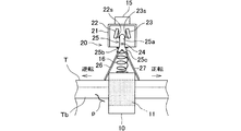
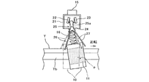
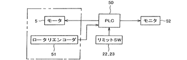
- FIG. 1 is a schematic plan view of a protruding code detection device according to an embodiment of the present invention. It is the side view made into the partial cross section of the code
- FIG. 3 is a partially enlarged side view of FIG. It is the side view which abbreviate
- T ... tyre, Tb ... bead part, p ... protruding cord, n ... cereal number, DESCRIPTION OF SYMBOLS 1 ... Projection code detection apparatus, 2 ... Turntable, 3 ... Rotating shaft, 5 ... Motor, 6 ... Gear, 8 ... Positioning slider, 10: Displacement member with surface fastener, 11 ... Surface fastener, 15 ... Support member, 16 ... Coil spring, 20 ... Displacement detector, 21 ... Switch box, 22, 23 ... Limit switch, 24 ... Support shaft, 25 ... Swing member, 26, 27 ... Metal rod, 50 ... PLC, 51 ... Rotary encoder, 52 ... Monitor.
- FIGS. Schematic diagrams of the protruding code detection device 1 according to the present embodiment are shown in FIGS.
- the code detection device 1 the tire T to be inspected is placed at a predetermined position on the rectangular turntable 2.
- the turntable 2 is horizontally fixed and supported at the upper end of the vertically oriented rotating shaft 3, and the rotational power of the drive shaft of the motor 5 is transmitted to the rotating shaft 3 through the meshing of the gears 6 and 7 to rotate.
- the shaft 3 rotates with the turntable 2.
- the turntable 2 constitutes a rotating means.
- four positioning sliders 8 that slide in the radial direction from the central axis C of the rotary shaft 2 are provided at equal intervals in the circumferential direction, and the four positioning sliders 8 always have the central axis C. Are configured to be linked to each other so as to slide while maintaining the same distance from each other. Therefore, by positioning the four positioning sliders 8 so as to grip the tire T from the outside, the center of the tire T can be easily aligned with the central axis C (centering).
- the support member 15 for suspending the displacement member 10 with the hook-and-loop fastener via the coil spring 16 is provided above the tire T placed centered on the upper surface of the turntable 2.
- a moving mechanism (not shown) that holds the support member 15 and moves in a predetermined radial direction or moves up and down is provided.
- the displacement member 10 with the surface fastener is supported so as to be adjacent to the inner side in the radial direction of the bead portion Tb on the inner peripheral edge of the tire T and to face the bead portion Tb.
- the displacement member 10 with the hook-and-loop fastener constitutes a hooking means.
- the support member 15 and the coil spring 16 constitute a support means.
- the displacement member 10 with a hook-and-loop fastener is attached to the lower end of the coil spring 16 projecting downward from the support member 15.
- the coil spring 16 has a large spring constant and mainly uses bending elasticity rather than vertically expanding and contracting, and the displacement member 10 with the hook-and-loop fastener can be displaced in the lateral direction when the coil spring 16 is bent.
- the displacement member 10 with the hook-and-loop fastener suspended by the coil spring 16 has a concave portion 10a curved along the surface shape of the bead portion Tb on the inner peripheral edge of the tire T.
- a hook-and-loop fastener 11 having a large number of loops planted on the inner surface is attached.
- the displacement member 10 with the surface fastener is suspended while the recess 10 a of the displacement member 10 with the surface fastener is loosely fitted to the bead portion Tb on the upper side of the tire T. More precisely, as shown in FIG. 3, in the displacement member 10 with the surface fastener, the surface fastener 11 provided on the inner surface of the recess 10a covering the surface of the bead portion b of the tire T is adjacent to the surface of the bead portion Tb. It is hung in the position to do.
- the cord of the tire constituent member may protrude from the surface, and the protruding cord p protrudes from the surface. Contact the loop of the fastener 11 (see FIG. 4).
- the motor 3 is driven to rotate the turntable 1 forward or backward.
- the displacement member 10 with the surface fastener relatively moves along the bead portion Tb of the tire T.
- the protruding cord p protruding from the bead portion b of the tire T protrudes in the direction opposite to the rotation direction of the tire T, the protruding cord p comes into contact with the loop of the hook-and-loop fastener 11 but slips on the loop and is caught. Absent.
- the protruding cord p protrudes substantially in the rotational direction of the tire T
- the turning protruding cord p bites into the loop of the hook and loop fastener 11 and is pulled together with the hook and loop fastener 11 to pull the displacement member 10 with the hook and loop fastener.
- the coil spring 16 bends elastically.
- the protruding cord p protruding from the bead portion b of the tire T is caught by the surface fastener 11 by either the forward rotation or the reverse rotation of the tire T, and the displacement member 10 with the surface fastener is displaced.
- a displacement detection device 20 for detecting the displacement of the displacement member 10 with the surface fastener is attached to the support member 15.
- a switch box 21 is fixed to the support member 15, and limit switches 22 and 23 of the displacement detector 20 are built in the switch box 21 (see FIGS. 4 and 5).
- left and right limit switches 22 and 23 are arranged symmetrically in the switch box 20, and the swing member 25 is pivotally supported on the support shaft 24 between the left and right limit switches 22 and 23. Is swingably provided.
- the swing member 25 has an upper extending portion 25a extending upward from the support shaft 24.
- the upper extending portion 25a is provided on the left and right side surfaces of the operating pieces 22s and 23s of the left and right limit switches 22 and 23, respectively. It touches.
- the swing member 25 is bifurcated downward from the support shaft 24 to form a pair of lower branch portions 25b and 25c.
- the lower branch portions 25b and 25c projecting downward from the switch box 20 are formed.
- the thin metal rods 26 and 27 having elasticity extend obliquely downward away from each other.
- the two metal rods 26 and 27 extending obliquely downward away from each other extend so that their lower portions sandwich the displacement member 10 with surface fasteners from both the left and right sides. Therefore, when the displacement member 10 with the surface fastener is displaced left or right, one of the metal rods 26, 27 is pushed by the displacement member 10 with the surface fastener, and the swing member 25 swings.
- the upper extending portion 24a operates the operating pieces 22s and 23s of the left and right limit switches 22 and 23 to turn on the switches (see FIG. 5).
- the cord detection device 1 for detecting the protruding cord p of the bead portion b of the tire T is sequence-controlled by a PLC (Programmable Logic Controller) 50, and the PLC 50 controls the motor 5 as shown in FIG. Is provided with a rotary encoder 51.
- a signal detected by the rotary encoder 51 is input to the PLC 50, and the rotational speed of the tire T mounted on the turntable 2 is calculated from the motor rotational speed and the motor rotational speed.
- the PLC 50 monitors the state of the limit switches 22 and 23, and the ON signal of the limit switches 22 and 23 is input. The detection result of the protruding cord p is displayed on the monitor 52.
- the tire T is centered and placed on the turntable 2.
- the portion of the tire T to which the serial number n is attached is made to coincide with the direction in which the displacement member 10 with the surface fastener is set as viewed from the central axis C (see FIG. 1).
- the tire T is placed on the turntable 2 with the bead portion Tb on the side to which the serial number n is attached (the serial side) facing up.
- the radial position for suspending the displacement member 10 with the surface fastener is obtained by calculation from the outer dimensions of the tire T, and the vertical position is also matched with the upper bead portion Tb of the tire T placed on the turntable 2.
- the displacement member 10 with the surface fastener is set at a position where the surface fastener 11 provided on the inner surface of the recess 10a covering the surface of the bead portion b of the tire T is close to the surface of the bead portion Tb.
- the motor 5 is driven to rotate forward under the control of the PLC 50, and the tire T rotates in the forward rotation direction together with the turntable 2. If the bead portion Tb on the cereal side of the tire T does not have a protruding cord p that protrudes substantially in the normal rotation direction of the tire T, there is nothing to be caught by the surface fastener 11 of the displacement member 10 with the surface fastener, and the displacement member with the surface fastener. 10 is not displaced and the protruding code p is not detected.
- the bead portion Tb on the cereal side of the tire T has a protruding cord p that protrudes substantially in the normal rotation direction of the tire T, as shown in FIG. Since it is caught by the surface fastener 11 and the displacement member 10 with the surface fastener is displaced so as to be pulled in the forward rotation direction, one of the metal rods 27 of the displacement detector 20 is pushed, and the swinging member 25 swings. When the limit switch 22 is turned on, the protruding cord p is detected.
- the ON signal of limit switch 22 is input to PLC50. Since the PLC 50 monitors the rotation angle based on the serial number n of the tire T, the rotation angle ⁇ when the ON signal of the limit switch 22 is input indicates the position of the protruding cord p.
- the PLC 50 stores the position information (rotational direction and rotational angle ⁇ ) where this protruding cord p exists. At the same time, it is displayed on the monitor 52.
- the rotation of the tire T is stopped, so that it is possible to suitably prevent the surface fastener, the limit switch, and the like from being damaged by the rotational force. Further, when the rotation is continued as it is, the hooking of the protruding cord p on the hook and loop fastener 11 is released and the displacement member 10 with the hook and loop fastener returns to the original position so that a new protruding cord p can be detected. Become. Thus, if the tire T is rotated once in the forward rotation direction and one or a plurality of protruding cords p is detected, the position information is displayed on the monitor 52.
- the tire T is rotated in the reverse direction, and the protruding cord p protruding substantially in the reverse direction of the tire T is detected. If there is a detection, the position information is displayed on the monitor 52. In this way, by rotating the tire T in both the forward and reverse directions, it is possible to reliably detect whether the protruding cord p protrudes in any direction.
- the tire T is inverted and positioned on the turntable 2 with the bead portion Tb on the anti-cereal side facing up.
- the tire T is rotated in the normal rotation direction and the reverse rotation direction to detect the protruding cord p, and each of the protruding cords p is detected.
- the position information is displayed on the monitor 52.
- the protruding cord p of the bead portion Tb of the tire T can be detected promptly and surely with almost no manual labor. Time is also shortened. Further, the position information can be easily known together with the presence or absence of the protruding cord p.
- the tire T is reversed.
- the protruding code p can be detected at the same time for the upper and lower bead portions Tb and Tb without repeating the same process, and the detection work time can be substantially halved.
- the protruding cord p can be detected automatically. Further, the protruding cord p may be detected by fixing the tire T and rotating the displacement detection device.
Landscapes
- Physics & Mathematics (AREA)
- General Physics & Mathematics (AREA)
- Engineering & Computer Science (AREA)
- Mechanical Engineering (AREA)
- Tyre Moulding (AREA)
- Tires In General (AREA)
Abstract
労力を軽減し、速やかにかつ確実にタイヤビード部から突出することがあるコードを検出することができるタイヤビード部の突出コード検出方法および装置が開示される。タイヤTのビード部Tbから突出することがある突出コードpに引っ掛かる面ファスナ11を有する変位部材10が、タイヤTのビード部Tbに近接した状態でビード部Tbの内側に沿って相対的に回転移動させられる。突出コードpが面ファスナ11に引っ掛かると、変位部材10が支軸24回りで揺動することで、突出コードpの存在が検出される。
Description
本発明は、タイヤビード部に突出したコードを検出する方法および装置に関する。
製造されたタイヤには、ときにタイヤのビード部に表面から内部構成部材のコードが突出することがあり、かかる突出コードを検査するのに、従来人手に頼る部分が多かった。すなわち、作業員が手でビード部を触って触感で突出コードを検出し、または目視による視覚で突出コードを検出することが行われていた。
ところで、作業員の触覚による場合は、手に怪我をしないように手袋をはめて検査すると、感触が微妙となり見落としのおそれが大きくなり、正確に検査しようとなると熟練を要することになる。また、視覚による場合も、光の当たり具合によって見落としのおそれがあり、正確に検査しようとなると熟練を要することになる。
いずれにしても、作業員の人手によりタイヤビード部の突出コードを検出すると、確実に検査しようとなると、作業労力と作業時間が多く要することになる。
本発明は、かかる点に鑑みなされたもので、その目的とする処は、労力を軽減し、速やかにかつ確実にタイヤビード部の突出コードを検出することができるタイヤビード部の突出コード検出方法および装置を供する点にある。
上記目的を達成するために、本発明の一態様(Aspect)によれば、タイヤのビード部から突出することがある突出コードに引っ掛かる引掛り手段を、タイヤのビード部に隣接した状態でビード部に沿って相対的に回転移動させ、突出コードが前記引掛り手段に引っ掛かかることによる前記引掛り手段の回転移動方向への変位を検知し、前記引掛り手段の変位により突出コードを検出することを特徴とするタイヤビード部の突出コード検出方法が提供される。
本発明の好適な実施形態では、前記引掛り手段を前記タイヤのビード部に隣接して配置し、前記タイヤを回転する。
本発明のタイヤビード部の突出コード検出方法では、好適には、前記引掛り手段として、前記タイヤのビード部の表面形状に沿って湾曲した面ファスナを有する変位部材を用いる。
上記目的を達成するために、本発明の他の態様(Aspect)によれば、タイヤのビード部から突出することがある突出コードに引っ掛かる引掛り手段と、タイヤをタイヤ中心軸を中心に回転する回転手段と、前記引掛り手段を、前記タイヤのビード部に隣接し多少の回転方向への変位を許して支持する支持手段と、前記引掛り手段の回転方向への変位を検知する変位検知手段とを備えるタイヤビード部の突出コード検出装置が提供される。
本発明のタイヤビード部の突出コード検出装置では、好適には、前記変位検出手段は、前記引掛り手段の回転方向への変位により作動するリミットスイッチを有する。
好適には、前記引掛り手段は、前記タイヤのビード部の表面形状に沿った形状の面ファスナを有する。
また、好適には、前記支持手段は、前記引掛り手段を支持するスプリングを含む。
さらに、好適には、前記支持手段は、タイヤに対し相対移動可能の支持部材を含み、前記変位検知手段は、支持部材に揺動可能に支持された揺動部材と、揺動部材から前記引掛り手段に係合可能に突出する1対の棒と、揺動部材の揺動を検出する手段とを含む。
また、好適には、前記支持手段は、前記引掛り手段を支持するスプリングを含む。
さらに、好適には、前記支持手段は、タイヤに対し相対移動可能の支持部材を含み、前記変位検知手段は、支持部材に揺動可能に支持された揺動部材と、揺動部材から前記引掛り手段に係合可能に突出する1対の棒と、揺動部材の揺動を検出する手段とを含む。
本発明によるタイヤビード部の突出コード検出方法によれば、タイヤのビード部から突出することがある突出コードに引っ掛かる引掛り手段を、タイヤのビード部に隣接した状態でタイヤに対し相対的に回転移動させて、引掛り手段の回転方向への変位を検知するので、タイヤビード部に突出コードが突出していると、タイヤのビード部に対して隣接して相対的に回転移動する引掛り手段に突出コードが接触して引っ掛かり、引掛り手段を引っ張るようにして変位させることになり、この引掛り手段の変位を検出することで、労力を軽減し、簡単かつ速やかに突出コードを検出することができる。
引掛り手段をタイヤのビード部に隣接して配置し、タイヤの方を回転することにより、引掛り手段の方を回転させるより装置を簡素化して設備コストを抑えることができる。
引掛り手段が、タイヤのビード部の表面形状に沿って湾曲した面ファスナを備えることにより、突出コードとの引っ掛かりは面ファスナをある程度変位させる程度で、強固に面ファスナを引っ張ることはなく、連続して複数の突出コードを検出することができる。また、タイヤビード部に沿って引掛り手段を相対的に一周させることで、一方のビード部を全て検査することができる。
本発明によるタイヤビード部の突出コード検出装置によれば、回転手段によりタイヤ中心軸を中心に回転するタイヤのビード部に、引掛り手段が隣接し多少の回転方向への変位を許して支持されるので、タイヤビード部に突出コードが突出していると、タイヤのビード部に対して隣接して相対的に回転移動する引掛り手段に突出コードが接触して引っ掛かり、引掛り手段を引っ張るようにして変位させることになり、この引掛り手段の変位を変位検知手段が検出することで、労力を軽減し、簡単かつ速やかに突出コードを検出することができる。
変位検出手段が、引掛り手段の回転方向への変位によりリミットスイッチが作動するように構成することによって、装置を簡素化して設備コストを抑えることができる。
引掛り手段は、タイヤのビード部の表面形状に沿った形状の面ファスナを備えることにより、突出コードとの引っ掛かりは面ファスナをある程度変位させる程度で、強固に面ファスナを引っ張ることはなく、連続して複数の突出コードを検出することができる。そして、タイヤビード部に沿って引掛り手段を相対的に一周させることで、一方のビード部を全て検査することができる。
T…タイヤ、Tb…ビード部、p…突出コード、n…セリアル番号、
1…突出コード検出装置、2…ターンテーブル、3…回転軸、5…モータ、6…ギヤ、8…位置決めスライダ、
10…面ファスナ付き変位部材、11…面ファスナ、15…支持部材、16…コイルスプリング、
20…変位検知装置、21…スイッチボックス、22,23…リミットスイッチ、24…支軸、25…揺動部材、26,27…金属棒、
50…PLC、51…ロータリエンコーダ、52…モニタ。
1…突出コード検出装置、2…ターンテーブル、3…回転軸、5…モータ、6…ギヤ、8…位置決めスライダ、
10…面ファスナ付き変位部材、11…面ファスナ、15…支持部材、16…コイルスプリング、
20…変位検知装置、21…スイッチボックス、22,23…リミットスイッチ、24…支軸、25…揺動部材、26,27…金属棒、
50…PLC、51…ロータリエンコーダ、52…モニタ。
以下、本発明に係る一実施の形態について図1ないし図6に基づいて説明する。
本実施の形態に係る突出コード検出装置1の概略図を図1および図2に示す。
コード検出装置1において、検査に供されるタイヤTは、矩形のターンテーブル2の所定位置に載置される。ターンテーブル2は、鉛直に指向した回転軸3の上端に水平に固定支持されており、モータ5の駆動軸の回転動力がギヤ6,7の噛み合いを介して回転軸3に伝達されて、回転軸3がターンテーブル2とともに回転する。ターンテーブル2は回転手段を構成する。
本実施の形態に係る突出コード検出装置1の概略図を図1および図2に示す。
コード検出装置1において、検査に供されるタイヤTは、矩形のターンテーブル2の所定位置に載置される。ターンテーブル2は、鉛直に指向した回転軸3の上端に水平に固定支持されており、モータ5の駆動軸の回転動力がギヤ6,7の噛み合いを介して回転軸3に伝達されて、回転軸3がターンテーブル2とともに回転する。ターンテーブル2は回転手段を構成する。
ターンテーブル2の上面には回転軸2の中心軸線Cから径方向に摺動する位置決めスライダ8が周方向に等間隔に4か所設けられており、4つの位置決めスライダ8は、常に中心軸線Cからの距離を互いに等しく維持しながら摺動するように互いに連動するよう構成されている。したがって、4つの位置決めスライダ8がタイヤTを外側から掴むように位置決めすることでタイヤTの中心を中心軸Cに簡単に一致させること(センタリング)ができる。
こうして、ターンテーブル2の上面にセンタリングされて載置されたタイヤTの上方に、面ファスナ付き変位部材10をコイルスプリング16を介して吊設する支持部材15が設けられる。そして、支持部材15を保持して、所定の半径方向に移動したり昇降したりする移動機構(図示せず)が設けられている。面ファスナ付き変位部材10はタイヤTの内周縁のビード部Tbの径方向内側に隣接してそれに対面するように支持される。面ファスナ付き変位部材10は引掛り手段を構成する。また、支持部材15およびコイルスプリング16は、支持手段を構成する。
支持部材15から下方に突設されたコイルスプリング16の下端に面ファスナ付き変位部材10が取り付けられている。コイルスプリング16は、ばね定数が大きく、上下に伸縮するよりも主に曲げ弾性を利用するものであり、面ファスナ付き変位部材10はコイルスプリング16が曲がることにより横方向に変位可能である。
図3に示すように、コイルスプリング16により吊設された面ファスナ付き変位部材10は、タイヤTの内周縁のビード部Tbの表面形状に沿って湾曲した凹部10aを有し、同凹部10aの内面に多数のループを植設した面ファスナ11が取り付けられている。
この面ファスナ付き変位部材10の凹部10aが、図2に示すように、タイヤTの上側のビード部Tbに遊嵌する状態で面ファスナ付き変位部材10が吊設される。もう少し正確に記すと、面ファスナ付き変位部材10は、図3に示すように、タイヤTのビード部bの表面を覆う凹部10aの内面に設けられた面ファスナ11がビード部Tbの表面に隣接する位置に吊設される。
タイヤTの内周縁のビードリングbで折り返されるようにして形成されたビード部Tbには、タイヤ構成部材のコードが表面から突出していることがあり、同突出コードpが突出していると、面ファスナ11のループに接触する(図4参照)。
タイヤTに対して面ファスナ付き変位部材10を、このような位置に吊設した状態で、モータ3を駆動してターンテーブル1を正転または逆転する。これにより、タイヤTのビード部Tbに沿い面ファスナ付き変位部材10が相対移動する。そして、タイヤTのビード部bから突出する突出コードpがタイヤTの回転方向と逆方向に突出していると、同突出コードpは面ファスナ11のループに接触するもののループの上を滑って引っ掛からない。
逆に、突出コードpがタイヤTの回転方向に概ね向かって突出していると、旋回する同突出コードpは面ファスナ11のループに食い込んで引っ掛かり、面ファスナ11とともに面ファスナ付き変位部材10を引っ張るようにして回転方向に変位させる。このとき、コイルスプリング16は弾性的に曲がる。
なお、突出コードpが面ファスナ11に引っ掛かって面ファスナ付き変位部材10を変位させても、いずれ突出コードpは面ファスナ11から外れ、コイルスプリング16の弾性力により変位した面ファスナ付き変位部材10は元の位置に復帰する。
したがって、タイヤTのビード部bから突出する突出コードpは、タイヤTの正転か逆転のいずれかの回転によって面ファスナ11に引っ掛かり、面ファスナ付き変位部材10を変位させる。
この面ファスナ付き変位部材10の変位を検知する変位検知装置20が支持部材15に取り付けられている。支持部材15にはスイッチボックス21が固着されており、同スイッチボックス21に変位検知装置20のリミットスイッチ22,23が内蔵されている(図4,図5参照)。
図4に示すように、スイッチボックス20内に左右のリミットスイッチ22,23が左右対称に配置されており、左右のリミットスイッチ22,23の間に支軸24に軸支された揺動部材25が揺動自在に設けられている。
揺動部材25は、支軸24より上方に延出した上方延出部25aを有し、この上方延出部25aが、左右のリミットスイッチ22,23の作動片22s,23sにそれぞれ左右側面で接している。そして、揺動部材25は、支軸24より下方が2又に分岐して1対の下方分岐部25b,25cを形成しており、スイッチボックス20より下方に突出した各下方分岐部25b,25cから弾性を有する細い金属棒26,27が互いに離れる斜め下方に延びている。
互いに離れる斜め下方に延びた2本の金属棒26,27は、その各下部が面ファスナ付き変位部材10を左右両側から挟むように延びている。
したがって、面ファスナ付き変位部材10が左右いずれかに変位すると、いずれかの金属棒26,27が面ファスナ付き変位部材10に押されて、揺動部材25が揺動し、揺動部材25の上方延出部24aが左右いずれかのリミットスイッチ22,23の作動片22s,23sを作動してスイッチをオンする(図5参照)。
したがって、面ファスナ付き変位部材10が左右いずれかに変位すると、いずれかの金属棒26,27が面ファスナ付き変位部材10に押されて、揺動部材25が揺動し、揺動部材25の上方延出部24aが左右いずれかのリミットスイッチ22,23の作動片22s,23sを作動してスイッチをオンする(図5参照)。
リミットスイッチ22,23のいずれかがオンすることで、タイヤTのビード部bから突出する突出コードpを検出することができる。
以上のタイヤTのビード部bの突出コードpを検出するコード検出装置1は、PLC(Programmable Logic Controller)50によりシーケンス制御され、図6に示すように、PLC50がモータ5を制御し、モータ5にはロータリエンコーダ51が備えられており、ロータリエンコーダ51により検出された信号はPLC50に入力されて、モータ回転数およびモータ回転数からターンテーブル2に載置されたタイヤTの回転角度が演算される。
以上のタイヤTのビード部bの突出コードpを検出するコード検出装置1は、PLC(Programmable Logic Controller)50によりシーケンス制御され、図6に示すように、PLC50がモータ5を制御し、モータ5にはロータリエンコーダ51が備えられており、ロータリエンコーダ51により検出された信号はPLC50に入力されて、モータ回転数およびモータ回転数からターンテーブル2に載置されたタイヤTの回転角度が演算される。
また、PLC50はリミットスイッチ22,23の状態を監視し、リミットスイッチ22,23のオン信号が入力される。突出コードpの検出結果は、モニタ52に表示される。
本コード検出装置1のシステム制御手順を以下に記述する。
まず、タイヤTをターンテーブル2にセンタリングして載置する。
そのとき、タイヤTのセリアル番号nが付された部分を、中心軸線Cから見て面ファスナ付き変位部材10がセットされる方向に一致させる(図1参照)。なお、初めにセリアル番号nが付された側(セリアル側)のビード部Tbを上にしてタイヤTをターンテーブル2に載置する。
まず、タイヤTをターンテーブル2にセンタリングして載置する。
そのとき、タイヤTのセリアル番号nが付された部分を、中心軸線Cから見て面ファスナ付き変位部材10がセットされる方向に一致させる(図1参照)。なお、初めにセリアル番号nが付された側(セリアル側)のビード部Tbを上にしてタイヤTをターンテーブル2に載置する。
次に、当該タイヤTの外形寸法から面ファスナ付き変位部材10を吊設する半径方向位置が演算により求められ、上下位置もターンテーブル2に載置されたタイヤTの上側のビード部Tbに合せて、図2に示すように、タイヤTのビード部bの表面を覆う凹部10aの内面に設けられた面ファスナ11がビード部Tbの表面に近接した位置に面ファスナ付き変位部材10がセットされる。
かかる状態で、PLC50に制御されてモータ5が正転駆動され、ターンテーブル2とともにタイヤTが正転方向に回転する。タイヤTのセリアル側のビード部Tbに概ねタイヤTの正転方向に向かって突出する突出コードpがなければ、面ファスナ付き変位部材10の面ファスナ11に引っ掛かるものがなく、面ファスナ付き変位部材10が変位することがなく、突出コードpは検出されない。
しかし、タイヤTのセリアル側のビード部Tbに概ねタイヤTの正転方向に向かって突出する突出コードpがあると、図5に示すように、当該突出コードpが面ファスナ付き変位部材10の面ファスナ11に引っ掛かり、面ファスナ付き変位部材10が正転方向に引っ張られるように変位するので、変位検知装置20の一方の金属棒27が押されて揺動部材25が揺動し、一方のリミットスイッチ22をオンして突出コードpが検出される。
リミットスイッチ22のオン信号はPLC50に入力される。PLC50は、タイヤTのセリアル番号nを基準にした回転角度を監視しているので、リミットスイッチ22のオン信号を入力したときの回転角度θが、突出コードpの位置を示している。
すなわち、タイヤTのセリアル番号nから正転方向に角度θの位置に突出コードpが存在することが分かり、この突出コードpが存在する位置情報(回転方向と回転角度θ)はPLC50が記憶するとともに、モニタ52に表示する。
突出コードpを検出したとき、タイヤTの回転を停止することで、面ファスナ、リミットスイッチ等を回転の力で損傷することを好適に防止することができる。また、そのまま回転を継続した場合は、面ファスナ11への突出コードpの引っ掛かりは外れて面ファスナ付き変位部材10は元の位置に戻り、新たな突出コードpの検出を行うことができるようになる。
こうして、タイヤTを正転方向に一回転し、1つまたは複数の突出コードpの検出があれば、その各位置情報をモニタ52に表示する。
こうして、タイヤTを正転方向に一回転し、1つまたは複数の突出コードpの検出があれば、その各位置情報をモニタ52に表示する。
次に、タイヤTを逆転方向に回転して、今度は概ねタイヤTの逆転方向に向かって突出する突出コードpの検出を行い、検出があれば、その位置情報をモニタ52に表示する。
このように、タイヤTの正転および逆転の両方向の回転を行うことで、突出コードpがいずれの方向に向かって突出していても確実に検出することができる。
このように、タイヤTの正転および逆転の両方向の回転を行うことで、突出コードpがいずれの方向に向かって突出していても確実に検出することができる。
このようにして、セリアル側のビード部Tbについて突出コードpの検出を行った後は、タイヤTを反転して反セリアル側のビード部Tbを上にしてターンテーブル2に位置決めして載置し、反セリアル側のビード部Tbについて前記と同様にタイヤTを正転および逆転方向に回転して突出コードpの検出作業を行い、1つまたは複数の突出コードpの検出があれば、その各位置情報をモニタ52に表示する。
以上に述べた突出コード検出装置によれば、殆ど人手に頼ることなく、タイヤTのビード部Tbの突出コードpを速やかに、かつ確実に検出することができ、労力が軽減されるとともに、作業時間も短縮される。また、突出コードpの有無とともに、その位置情報を容易に知ることができる。
なお、変位検知装置20に相当する装置を別にもう1つ用意して、ターンテーブル2に載置されたタイヤTの上側と下側のビード部Tb,Tbにそれぞれセットすれば、タイヤTを反転して同じ工程を繰り返すことなく、上下のビード部Tb,Tbについて同時に突出コードpの検出をすることができ、検出作業時間を略半減することができる。
ターンテーブル2へのタイヤTの載置もロボットハンドなどの機構を用い、センタリングもモータ等で行うようにすれば、全自動で突出コードpの検出をすることができる。また、タイヤTを固定して、変位検出装置の方を回転させて、突出コードpを検出するようにしてもよい。
Claims (8)
- タイヤのビード部から突出することがある突出コードに引っ掛かる引掛り手段を、タイヤのビード部に隣接した状態でビード部に沿って相対的に回転移動させ、
突出コードが前記引掛り手段に引っ掛かかることによる前記引掛り手段の回転移動方向への変位を検知し、
前記引掛り手段の変位により突出コードを検出する
ことを特徴とするタイヤビード部の突出コード検出方法。 - 前記引掛り手段を前記タイヤのビード部に隣接して配置し、
前記タイヤを回転する
ことを含むことを特徴とする請求項1記載のタイヤビード部の突出コード検出方法。 - 前記引掛り手段として、前記タイヤのビード部の表面形状に沿って湾曲した面ファスナを有する変位部材を用いることを特徴とする請求項1または請求項2記載のタイヤビード部の突出コード検出方法。
- タイヤのビード部から突出することがある突出コードに引っ掛かる引掛り手段と、
タイヤをタイヤ中心軸を中心に回転する回転手段と、
前記引掛り手段を、前記タイヤのビード部に隣接し多少の回転方向への変位を許して支持する支持手段と、
前記引掛り手段の回転方向への変位を検知する変位検知手段と
を備えることを特徴とするタイヤビード部の突出コード検出装置。 - 前記変位検出手段は、前記引掛り手段の回転方向への変位により作動するリミットスイッチを有することを特徴とする請求項4記載のタイヤビード部の突出コード検出装置。
- 前記引掛り手段は、前記タイヤのビード部の表面形状に沿った形状の面ファスナを有することを特徴とする請求項4または請求項5記載のタイヤビード部の突出コード検出装置。
- 前記支持手段は、前記引掛り手段を支持するスプリングを含むことを特徴とする請求項4または請求項5記載のタイヤビード部の突出コード検出装置。
- 前記支持手段は、タイヤに対し相対移動可能の支持部材を含み、前記変位検知手段は、
支持部材に揺動可能に支持された揺動部材と、揺動部材から前記引掛り手段に係合可能に突出する1対の棒と、揺動部材の揺動を検出する手段とを含むことを特徴とする請求項4または請求項5記載のタイヤビード部の突出コード検出装置。
Applications Claiming Priority (2)
| Application Number | Priority Date | Filing Date | Title |
|---|---|---|---|
| JP2008132070A JP2009281776A (ja) | 2008-05-20 | 2008-05-20 | タイヤビード部のコード検出方法および装置 |
| JP2008-132070 | 2008-05-20 |
Publications (1)
| Publication Number | Publication Date |
|---|---|
| WO2009142111A1 true WO2009142111A1 (ja) | 2009-11-26 |
Family
ID=41340043
Family Applications (1)
| Application Number | Title | Priority Date | Filing Date |
|---|---|---|---|
| PCT/JP2009/058613 Ceased WO2009142111A1 (ja) | 2008-05-20 | 2009-05-07 | タイヤビード部の突出コード検出方法および装置 |
Country Status (2)
| Country | Link |
|---|---|
| JP (1) | JP2009281776A (ja) |
| WO (1) | WO2009142111A1 (ja) |
Citations (5)
| Publication number | Priority date | Publication date | Assignee | Title |
|---|---|---|---|---|
| JPH0330845Y2 (ja) * | 1984-03-22 | 1991-06-28 | ||
| JPH061128A (ja) * | 1992-06-23 | 1994-01-11 | Yokohama Rubber Co Ltd:The | タイヤビード部の内周長計測機 |
| JP2507906Y2 (ja) * | 1990-02-02 | 1996-08-21 | 横浜ゴム株式会社 | 加硫タイヤのライナ―ゲ―ジ検査装置 |
| JPH10170238A (ja) * | 1996-12-06 | 1998-06-26 | Bridgestone Corp | 被検査物の外形状異常判別方法及び装置 |
| JP2001334808A (ja) * | 2000-05-25 | 2001-12-04 | Bridgestone Corp | タイヤのカーカスプライ及びその製造方法 |
-
2008
- 2008-05-20 JP JP2008132070A patent/JP2009281776A/ja active Pending
-
2009
- 2009-05-07 WO PCT/JP2009/058613 patent/WO2009142111A1/ja not_active Ceased
Patent Citations (5)
| Publication number | Priority date | Publication date | Assignee | Title |
|---|---|---|---|---|
| JPH0330845Y2 (ja) * | 1984-03-22 | 1991-06-28 | ||
| JP2507906Y2 (ja) * | 1990-02-02 | 1996-08-21 | 横浜ゴム株式会社 | 加硫タイヤのライナ―ゲ―ジ検査装置 |
| JPH061128A (ja) * | 1992-06-23 | 1994-01-11 | Yokohama Rubber Co Ltd:The | タイヤビード部の内周長計測機 |
| JPH10170238A (ja) * | 1996-12-06 | 1998-06-26 | Bridgestone Corp | 被検査物の外形状異常判別方法及び装置 |
| JP2001334808A (ja) * | 2000-05-25 | 2001-12-04 | Bridgestone Corp | タイヤのカーカスプライ及びその製造方法 |
Also Published As
| Publication number | Publication date |
|---|---|
| JP2009281776A (ja) | 2009-12-03 |
Similar Documents
| Publication | Publication Date | Title |
|---|---|---|
| US10286552B2 (en) | Method for operating a brake and an associated machine, in particular a robot | |
| JP5370128B2 (ja) | ロボットの故障検出装置 | |
| US20150328774A1 (en) | Robot system controlling method, program, recording medium, robot system, and diagnosis apparatus | |
| JP7155664B2 (ja) | シミュレーション装置、制御装置およびロボット | |
| CN102756374A (zh) | 机械手控制器、简易设置型机械手及其控制方法 | |
| JP2016144861A (ja) | ロボット装置、ロボット制御方法、プログラム及び記録媒体 | |
| JP2017019080A5 (ja) | 制御方法 | |
| CN112313439B (zh) | 监控阀的操作状态 | |
| JP2013158876A5 (ja) | ||
| US20210107135A1 (en) | Teaching Method | |
| JP6564093B2 (ja) | 自動靴紐装着装置及び自動靴紐装着方法 | |
| JP2019520227A (ja) | ロボットの構成要素用の可動ハードストップ | |
| CN104677628B (zh) | 一种用于舱外航天服的关节运动寿命测试装置 | |
| JP2017052040A (ja) | ロボット | |
| CN104802802B (zh) | 一种用于摆臂式履带机器人零位校准的误差辨识方法 | |
| CN107199562B (zh) | 机器人控制装置和机器人控制方法 | |
| WO2009142111A1 (ja) | タイヤビード部の突出コード検出方法および装置 | |
| JP2007121575A5 (ja) | ||
| JP5605100B2 (ja) | ロープテスタ保持用治具 | |
| JP2525057B2 (ja) | 配管自動検査装置 | |
| CN113686563B (zh) | 一种用于机器人侧翻试验的试验方法及系统 | |
| CN116238869B (zh) | 链条在线磨损检测方法、检测系统、控制装置及设备 | |
| JP2006122740A (ja) | 塗布量検査手段を備えたシーリング装置 | |
| US11733720B2 (en) | Indexer and method of use thereof | |
| JP6421550B2 (ja) | 組立機 |
Legal Events
| Date | Code | Title | Description |
|---|---|---|---|
| 121 | Ep: the epo has been informed by wipo that ep was designated in this application |
Ref document number: 09750473 Country of ref document: EP Kind code of ref document: A1 |
|
| NENP | Non-entry into the national phase |
Ref country code: DE |
|
| 122 | Ep: pct application non-entry in european phase |
Ref document number: 09750473 Country of ref document: EP Kind code of ref document: A1 |