WO2009139175A1 - 清掃用具、清掃体ホルダ - Google Patents
清掃用具、清掃体ホルダ Download PDFInfo
- Publication number
- WO2009139175A1 WO2009139175A1 PCT/JP2009/002126 JP2009002126W WO2009139175A1 WO 2009139175 A1 WO2009139175 A1 WO 2009139175A1 JP 2009002126 W JP2009002126 W JP 2009002126W WO 2009139175 A1 WO2009139175 A1 WO 2009139175A1
- Authority
- WO
- WIPO (PCT)
- Prior art keywords
- cleaning
- connecting portion
- holding
- holding body
- cleaning tool
- Prior art date
Links
Images


Classifications
-
- A—HUMAN NECESSITIES
- A47—FURNITURE; DOMESTIC ARTICLES OR APPLIANCES; COFFEE MILLS; SPICE MILLS; SUCTION CLEANERS IN GENERAL
- A47L—DOMESTIC WASHING OR CLEANING; SUCTION CLEANERS IN GENERAL
- A47L13/00—Implements for cleaning floors, carpets, furniture, walls, or wall coverings
- A47L13/10—Scrubbing; Scouring; Cleaning; Polishing
- A47L13/20—Mops
- A47L13/24—Frames for mops; Mop heads
- A47L13/254—Plate frames
- A47L13/256—Plate frames for mops made of cloth
-
- A—HUMAN NECESSITIES
- A47—FURNITURE; DOMESTIC ARTICLES OR APPLIANCES; COFFEE MILLS; SPICE MILLS; SUCTION CLEANERS IN GENERAL
- A47L—DOMESTIC WASHING OR CLEANING; SUCTION CLEANERS IN GENERAL
- A47L13/00—Implements for cleaning floors, carpets, furniture, walls, or wall coverings
- A47L13/10—Scrubbing; Scouring; Cleaning; Polishing
- A47L13/20—Mops
- A47L13/24—Frames for mops; Mop heads
- A47L13/254—Plate frames
Definitions
- the present invention relates to a cleaning tool, and more particularly to a construction technique of a cleaning tool including a cleaning body used for cleaning a cleaning target.
- Japanese Laid-Open Patent Publication No. 9-154791 discloses a cleaning tool having a cleaning cloth and a handle for detachably holding the cleaning cloth inserted in an accommodation area provided in the cleaning cloth.
- This cleaning tool has the possibility of wiping and cleaning the object to be cleaned, but when designing a cleaning tool of this type that holds the cleaning body by inserting the holder on the holder side into the insertion area of the cleaning body. , There is a request to build an effective holder structure to carry out the cleaning work smoothly,
- this invention is made
- the invention described in each claim is configured.
- the invention described in each of these claims is for areas to be cleaned indoors, outdoors, and outdoors in detached houses, condominiums, buildings, factories, vehicles, etc. (floor surfaces, wall surfaces, windows, ceiling surfaces, outer wall surfaces, pillars, furniture surfaces, clothing , Curtains, blinds, bedding, lighting, electrical cords, household appliances, etc.) and cleaning tool structures for cleaning a region to be cleaned in each component of the human body.
- These various areas to be cleaned may be configured as a flat surface, or may be configured as a curved surface, an uneven surface, or a step surface.
- the cleaning tool according to the present invention is used for cleaning an object to be cleaned, and includes at least a cleaning body holder and a cleaning body.
- the cleaning body holder is configured as a long member.
- This cleaning body holder is configured to have a gripping part gripped by a user and a holding body extending in a longitudinal direction from a connecting part connected to the gripping part.
- the gripping part and the holding body may have an integral structure or a separate structure.
- the holding body fulfills the function of holding the cleaning body by being inserted into an insertion region provided in the cleaning body.
- One or more holding bodies can be provided as necessary.
- the holding body is inclined so that the height in the direction intersecting with the extending direction of the holding body is increased from the distal end side inserted first into the insertion region toward the connecting portion side. It is set as the structure which has a part. That is, the holding body is configured to have an inclined portion in which the height (thickness) of the holding body changes in an increasing manner from the distal end side toward the connecting portion side in the extending direction of the holding body. With respect to this configuration, the inclined portion can constitute all or part of the holding body. Moreover, regarding the increase / decrease in the height in an inclined part, the aspect increased / decreased linearly, the aspect increased / decreased curvedly, the aspect increased / decreased stepwise, etc. are included.
- the “height in the direction intersecting the extending direction of the holding body” here is typically defined as the height in the vertical direction of the holding body in a normal cleaning operation state.
- the flexibility increases as it goes from the connecting portion side of the holding body toward the distal end portion side, and on the other hand, the flexibility of the holding body is ensured.
- rigidity or strength increases from the front end side of the holding body toward the connecting portion side, it is possible to strengthen the portion of the holding body on the connecting portion side. This facilitates the cleaning process.
- the cleaning body is a disposable type that is intended for single use, or is replaced with multiple uses while retaining dust, dust, dust, etc. removed from the object to be cleaned. It may be of a disposable type that performs the above or may be of a type that can be used repeatedly after washing.
- the said inclination part is a structure connected to a connection part, and the height regarding the direction which cross
- the first connecting portion relates to a cross-sectional shape in a direction intersecting with the extending direction of the holding body, and a standing base plate extending up from the both ends of the bottom plate portion and the bottom plate portion.
- An upper plate portion extending between the standing portions above the bottom plate portion, a partition region defined by the bottom plate portion, the standing portion, and the upper plate portion, and an opening formed in the upper plate portion.
- the second connecting portion includes an insertion portion that is engaged by being inserted into the partition region, and a connecting portion that is provided to be connected to the upper side of the insertion portion and is narrower than the opening width of the opening portion. It is preferable that the connecting portion is exposed to the upper region through the opening in the engaged state where is inserted into the partition region. According to such a configuration, when the first connecting portion and the second connecting portion are connected, it is possible to prevent the front and back from being reversed and connected.
- the connecting portion connected to the inserting portion is in the way. Therefore, since the insertion portion cannot be inserted into the partition region, it is possible to prevent the first connection portion and the second connection portion from being connected in an incorrect form.
- an engagement protrusion is provided in one surface among the opposing surfaces where the said baseplate part and an insertion part oppose, and an engagement protrusion can engage with the other surface. It is preferable that the gripping portion and the holding body are locked to each other by the engagement of the engagement protrusion and the engagement hole. According to such a configuration, the engagement protrusion and the engagement hole are not visible from the outside, the appearance is improved, and dirt and dust are prevented from adhering to the engagement protrusion and the engagement hole. Thus, a stable connection operation at the first connecting portion and the second connecting portion is possible.
- the holding body has a structure extending in a plurality of lengths in parallel from the connecting portion.
- parallel may be a form in which a plurality of holding bodies are juxtaposed, and a form in which a plurality of holding bodies are arranged in parallel, or a distance between two adjacent holding bodies on the tip side. A form that is reduced as it goes is included. According to such a configuration, in each holding body of the cleaning body holder, it is possible to achieve both the securing of the flexibility of the holding body and the reinforcement of the portion on the base end side of the holding body.
- the cleaning body holder which concerns on this invention is an elongate cleaning body holder with which the cleaning body used for cleaning of cleaning object is mounted
- the cleaning body holder which comprises each said cleaning tool substantially It has the same configuration. Therefore, according to the cleaning body holder according to the present invention, in one or a plurality of holding bodies of the cleaning body holder, the flexibility of the holding body and the strengthening of the portion on the connecting portion side of the holding body are achieved. It is possible to achieve both. Moreover, according to the cleaning body holder which concerns on this invention, it becomes possible to aim at reinforcement
- the cleaning body holder which concerns on this invention, it can prevent that a 1st connection part and a 2nd connection part are connected with an incorrect form.
- the engagement protrusion and the engagement hole are not visible from the outside, the appearance is improved, and dirt and dust adhere to the engagement protrusion and the engagement hole. By preventing this, a stable connection operation at the first connecting portion and the second connecting portion is possible.
- a cleaning body holder that contributes to smoothing of a cleaning operation is provided. It became possible.
- cleaning tool 100 As cleaning objects to be wiped and cleaned using this cleaning tool 100, areas to be cleaned in a house, an apartment, a building, a factory, a vehicle, etc., outdoors, outdoors (floor surface, wall surface, window, ceiling surface, outer wall surface, Furniture surface, clothes, curtains, bedding, lighting, home appliances, etc.) and areas to be cleaned in each component of the human body. These various areas to be cleaned may be configured as a flat surface, or may be configured as a curved surface, an uneven surface, or a step surface.
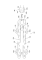
- FIG. 1 shows a perspective view of a state before the cleaning body 110 and the cleaning body holder 120 constituting the cleaning tool 100 of the present embodiment are assembled together. As shown in FIG. 1, the cleaning tool 100 is roughly divided into a cleaning body 110 and a cleaning body holder 120.
- the cleaning body 110 is a cleaning body having a wiping function for wiping off dirt in an area to be cleaned, a cleaning function for cleaning, or a function for cleaning off dirt.
- the cleaning body 110 is formed into a sheet shape or a flat plate shape at the time of sale or when it is not used, and is unraveled at the time of use to be bulky.
- the cleaning body 110 is a sheet body having a rectangular plan view as shown in FIG. 1 and extends in a long shape in a predetermined longitudinal direction (extending direction of the long side). And a structure in which the cleaning body main body 111 and the holding sheet 112 stacked on each other are welded and joined at welding joints 113 and welding joints 114 and 114 extending in parallel (in parallel). Is done.
- the weld joint 113 and the weld joints 114 and 114 may each be configured to extend continuously, or may be configured to extend intermittently. Further, the extension lengths of the weld joint 113 and the weld joints 114 and 114 can be appropriately selected as necessary.
- the pair of left and right spaces defined by the welding joint portion 113 and the welding joint portions 114, 114 are inserted regions 115 into which the holding body portion of the cleaning body holder 120 (holding plates 132, 132 of the holder main body 130 described later) is inserted. , 115.
- Each insertion region 115 has a shape (insertion width and insertion depth) in which each holding plate 132 of the holder main body 130 can be inserted. Further, in each insertion region 115, the welding width of the welded joints 114 and 114 is adjusted so that the insertion width of both end portions exceeds the insertion width of the central portion.
- the cleaning body 110 here corresponds to the “cleaning body” in the present invention.
- this cleaning body 110 can also be comprised as a cleaning body of other shapes, such as a square in planar view.
- the inserted regions 115 and 115 here correspond to the “inserted region” in the present invention.
- the inserted regions 115 and 115 may be configured by arranging a single inserted portion in a long shape, or configured by disposing a plurality of inserted portions intermittently. May be.
- the cleaning body holder 120 is detachable from the cleaning body 110 configured as described above, and is configured as a long member including a holder main body 130 and a handle portion 140 that are connected to each other.
- This cleaning body holder 120 corresponds to the “cleaning body holder” in the present invention.
- the handle portion 140 includes a handle main body 141 extending in a long shape, and a handle main body side connecting portion 142 interposed between the handle main body 141 and the holder main body 130.
- the handle body 141 is a part that is gripped by the user.
- the handle main body side connecting portion 142 constitutes a portion on the handle main body 141 side among portions where the handle main body 141 and the holder main body 130 are fixedly connected.
- the handle portion 140 or the handle main body 141 referred to here constitutes the “gripping portion” in the present invention.
- the holder main body 130 is a part having a function of detachably holding the cleaning body 110.
- the holder main body 130 is provided with a holder main body side connecting portion 131, a pair of left and right holding plates 132 and 132, and a presser plate 134 interposed between the handle main body 141.
- the pair of left and right holding plates 132, 132 are configured as longitudinal plate-like members extending in parallel (in parallel) on the same plane at a predetermined interval from the holder main body side connecting portion 131 toward the front. Is done. That is, the holder main body 130 has a fork shape in which the tip side is divided into two forks.
- the horizontal width of each holding plate 132 is set constant in the longitudinal direction or narrowly toward the tip.
- the holding plates 132 and 132 here correspond to the “holding body” in the present invention, and the holder main body side connecting portion 131 here constitutes the “connecting portion” in the present invention.
- the cross-sectional shape of the two holding plates 132, 132 can be a circular or polygonal bar shape.
- each holding plate 132 is provided with protrusions 133 and 133 at two places on the front and rear sides of the outer edge thereof.
- Each protrusion 133 has an elliptical shape whose outer shape protrudes toward the outside of the holding plate 132, and its protruding surface has a convex curve shape.
- each protrusion 133 is configured to have a hollow portion 133a whose central portion is open to increase the elastic force.
- the presser plate 134 is configured as a plate-like member that extends forward between the pair of left and right holding plates 132 and 132 and is curved so as to be convex downward.
- a locking projection (not shown) is provided on the lower surface.
- Each holding plate 132 can be inserted into a corresponding insertion region 115 formed in the cleaning body 110, and has a function of holding the cleaning body 110 in this inserted state.
- each holding plate 132 is fitted into the insertion region 115 on the cleaning body 110 side so as to be in close contact with each other, and gives a fixing action to the cleaning body 110.
- each insertion region 115 is configured such that the insertion width of both end portions exceeds the insertion width of the central portion. Therefore, in this insertion state, the front and rear projections 133 of each holding plate 132 are provided.
- each holding plate 132 is provided with a retaining action.
- the presser plate 134 presses the cleaning body 110 from above, and a locking projection (not shown) provided on the lower surface of the presser plate 134 acts as a stopper for the cleaning body 110.
- FIG. 2 shows a side view of the holding plate 132 of the holder main body 130 of the present embodiment
- FIG. 3 shows a plan view of the holder main body 130 of the present embodiment and the vicinity thereof.
- 4 shows a cross-sectional structure of each holding plate 132 in FIG. 3 with respect to the AA line
- FIG. 5 shows the holder main body side connecting portion 131 and the handle main body side connecting portion 142 in FIG.
- a cross-sectional structure with respect to the line BB is shown.
- FIG. 6 is a plan view of the holder main body 130 and its vicinity according to the present embodiment, and shows the structure of the holder main body side connecting portion 131 and the handle main body side connecting portion 142.
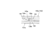
- FIG. 7 shows the locking structure between the engaging projection 138 on the holder main body side connecting portion 131 side and the engaging hole 143 on the handle main body side connecting portion 142 in FIG.
- FIG. 8 is a cross-sectional view, and FIG. 8 shows a locked state of the locking structure between the engaging protrusion 138 on the holder main body side connecting portion 131 side and the engaging hole 143 on the handle main body side connecting portion 142 side in FIG. It is taken as sectional drawing shown by.
- each holding plate 132 includes an inclined portion 136 on the upper surface 135 of the holding plate.
- the inclined portion 136 has a height (height H shown in FIG. 2) in a direction intersecting with the extending direction of the holding plate 132 at the tip end side (in FIG. 2) inserted in the insertion region 115 first.
- the left side in FIG. 3 is an inclined portion that is inclined so as to gradually increase from the connecting portion side (the right side in FIG. 2 and FIG. 3).
- the “height in the direction intersecting the extending direction of the holding plate 132” here is typically defined as the height in the vertical direction of the holding plate 132 in a normal cleaning operation state.
- the connecting portion side of the inclined portion 136 is connected to the holder main body side connecting portion 131, and the height H of the inclined portion 136 is maximized at the position connecting to the holder main body side connecting portion 131.
- the width (width D1 shown in FIG. 3) of the inclined portion 136 in the left-right direction is from the tip end side (left side in FIGS. 2 and 3) to the connecting portion side (right side in FIGS. 2 and 3). ), And is configured such that the width D1 is maximized at a location where the holder main body side connecting portion 131 is connected.
- the inclined portion 136 of the present embodiment has a height H that gradually decreases toward the tip end side of the holding plate 132 and gradually becomes thinner, and a width D1 that gradually decreases toward the tip end side. The width is gradually narrowed.
- the inclined portion 136 here corresponds to the “inclined portion” in the present invention.
- the flexibility increases as it goes toward the distal end side of the holding plate 132.
- the holder main body side connecting portion 131 and the portion connecting to the holder main body side connecting portion 131 are strengthened and the holder main body is strengthened. It is possible to provide connection stability when the side connecting portion 131 and the handle main body side connecting portion 142 are connected. This facilitates the cleaning operation.
- the height H and the width D1 of the inclined portion 136 provided on the holding plate 132 may be not only linearly increased / decreased, but also curved / stepped.
- the inclined portion 136 may be formed over substantially the entire extending direction of the holding plate 132 or may be formed over a part thereof. If necessary, a configuration in which the inclined portion 136 is not connected to the holder main body side connecting portion 131, for example, a configuration in which the end portion of the inclined portion 136 is formed in front of the holder main body side connecting portion 131 is adopted. You can also.
- each holding plate lower surface 137 of each holding plate 132 is provided with a thin portion 137a in which a portion corresponding to the inclined portion 136 protruding upward is thinned or thinned. . According to such a configuration, each holding plate 132 can be reduced in weight. The thin portion 137a can be omitted as necessary.
- each of the holder main body 130 and the handle portion 140 has a separate structure and can be assembled to each other.
- the structure of the cleaning body holder 120 in addition to the present configuration in which each of the holder main body 130 and the handle portion 140 is a separate structure, a configuration in which the holder main body 130 and the handle portion 140 are integrally molded, and the like are appropriately employed. You can also.
- the holder main body side connecting portion 131 and the handle on the holder main body 130 side.
- the handle main body side connecting portion 142 on the main body 141 side can be engaged.
- the holder main body side connecting portion 131 here corresponds to the “first connecting portion” in the present invention
- the handle main body side connecting portion 142 corresponds to the “second connecting portion” in the present invention.
- the convex engagement protrusion 138 provided in the upper surface of the holder main body side connection part 131 and the concave engagement hole 143 provided in the bottom face of the handle main body side connection part 142 are provided.
- a locked state in which the holder main body side connecting portion 131 and the handle main body side connecting portion 142 are locked to each other is formed.
- the engagement protrusion 138 is guided (guided) to the engagement hole 143 on the tip end side (left side in FIG. 6) of the bottom surface of the handle main body side connection portion 142 from the engagement hole 143.
- a guide hole 144 is provided.
- the holder main body side connecting portion 131 is related to a cross-sectional shape in a direction intersecting with the extending direction of the holding plate 132, a bottom plate portion 131 a, a standing portion 131 b, an upper plate portion 131 c, and a partition region 131d and the opening part 131e are provided at least.
- the bottom plate portion 131 a is configured as a bottom plate portion extending along the holding plate 132.
- the standing portions 131b and 131b are configured as standing portions that stand upward from both end portions of the bottom plate portion 131a.
- the upper plate portion 131c is configured as an upper plate portion extending between the standing portions 131b and 131b above the bottom plate portion 131a.
- the partition area 131d is defined as a space area partitioned by the bottom plate portion 131a, the standing portions 131b and 131b, and the upper plate portion 131c, thereby wrapping the insert (insertion portion 142a) from at least three directions and stably holding it.
- Structure also referred to as “box structure” or “pocket structure” is formed.
- the opening 131e is formed as an opening formed in the upper plate portion 131c and communicating the partition region 131d with the upper region 150 above the upper plate portion 131c, that is, the region outside the partition region 131d.
- the bottom plate portion 131a, the standing portion 131b, the upper plate portion 131c, the partition region 131d, the opening portion 131e, and the upper region 150 are referred to as “bottom plate portion”, “standing portion”, and “upper plate portion” in the present invention, respectively. , “Partition region”, “opening” and “upper region”.
- the handle main body side connecting portion 142 includes at least an insertion portion 142a and a connecting portion 142b.
- the insertion portion 142a is a convex flange portion (a flange portion) extending outward from the connecting portion 142b on the lower side of the handle main body side connecting portion 142, and is inserted into the partition region 131d of the holder main body side connecting portion 131. It is comprised as an insertion part engaged by doing.
- the connecting part 142b is connected to the upper side of the insertion part 142a and is configured as a part (a part having a width D2) narrower than the opening width D3 of the opening 131e.
- the connecting portion 142b is exposed to the upper region 150 through the opening 131e in the engaged state in which the insertion portion 142a is inserted into the partition region 131d.
- the insertion portion 142a and the connection portion 142b referred to here correspond to the “insertion portion” and the “connection portion” in the present invention, respectively.
- the insertion portion 142a and the connecting portion 142b may have an integral structure or a separate structure that can be separated.
- the opening width is smaller than the width of the connecting portion 142b, the holder main body side connecting portion 131 and the handle main body side connecting portion. Since the effect of preventing 142 from being connected in the wrong form is obtained in the same manner, the opening can be provided in the bottom plate portion 131a.
- the handle main body side connecting portion 142 As the insertion portion 142a is inserted into the partition region 131d, the insertion portion 142a and the bottom plate portion 131a are allowed to slide in the arrow direction in FIG. Become. At this time, by sliding the insertion portion 142a along the upper surface of the bottom plate portion 131a, the insertion portion 142a can be smoothly inserted into the partition region 131d, and thus the holder main body side connecting portion 131 and the handle main body side. It becomes possible to give the connection part 142 a sense of stability.
- a guide hole inclined portion 144 a having a form that substantially matches the inclination of the engaging protrusion inclined portion 138 a provided on the engaging protrusion 138 is provided at the end of the guide hole 144. Accordingly, in the sliding process, the engaging protrusion 138 is guided (guided) to the end of the guide hole 144, and then the guide hole inclined portion 144a rides on the engaging protrusion inclined portion 138a, and finally the engaging protrusion. 138 is fitted into the engagement hole 143.
- a locked state (also referred to as a locked state) in which the holder main body side connecting portion 131 and the handle main body side connecting portion 142 are locked to each other is formed, and the connection between the holder main body 130 and the handle portion 140 is completed.
- the engagement protrusion erection portion 138b and the engagement hole erection portion 143a are in a contact relationship by surface contact in the unlocking direction.
- the connection state of the holder main body 130 and the handle part 140 is prevented from being inadvertently released.
- it in the connected state of the holder main body 130 and the handle portion 140, it is a portion that cannot be seen from the outside, specifically, one of the opposing surfaces of the bottom plate portion 131a and the insertion portion 142a.
- the engagement protrusion 138 is provided on the upper surface of the bottom plate portion 131a and the engagement hole 143 is provided on the lower surface (bottom surface) of the insertion portion 142a which is the other surface, the engagement protrusion 138 and the engagement hole 143 are not visible from the outside. In addition to improving the appearance of the upper part, it is possible to stably connect the holder main body 130 and the handle part 140 by preventing dirt and dust from adhering to the engaging protrusions 138 and the engaging holes 143. .
- the engagement protrusion 138 here corresponds to the “engagement protrusion” in the present invention
- the engagement hole 143 here corresponds to the “engagement hole” in the present invention. If necessary, an engagement hole 143 may be provided on the upper surface of the bottom plate portion 131a, and an engagement protrusion 138 may be provided on the lower surface of the insertion portion 142a.
- the handle main body side connecting portion 142 and the holder main body side connecting portion are made of different types of resins or made of resins having different hardnesses. It is preferable to configure. For example, a combination of ABS (acrylonitrile butadiene styrene) resin and PP (polypropylene) resin, a combination of polyacetal resin and PE (polyethylene) resin, a combination of polycarbonate resin and PP (polypropylene) resin, acrylic resin and PE (polyethylene) resin It is possible to adopt a combination of these. According to such a configuration, in the sliding process, it is possible to reduce the wear of the abutting members and smoothly perform the operation when the guide hole inclined portion 144a rides on the engaging protrusion inclined portion 138a. Is possible.
- FIG. 9 is referred to regarding the specific configuration of the cleaning body 110.
- FIG. 9 is a perspective view showing a state in which the stacked portion of the cleaning body 110 is separated into each component.
- the cleaning body 110 of the present embodiment has a cleaning body main body 111 and a holding sheet 112 stacked in order from the upper cleaning target side (also referred to as “lower surface side” or “back surface side”) in FIG. 9.
- the cleaning body main body 111 is configured such that the cleaning target side sheet 111c, the fiber assembly 111b, and the base sheet 111a are laminated in order from the cleaning target side (lower surface side).
- the holding sheet 112 and the base sheet 111a are upper surface side sheets laminated on the opposite side of the cleaning target side sheet 111c (lower surface side sheet) with the fiber assembly 111b interposed therebetween.
- the base material sheet 111a, the fiber assembly 111b, and the cleaning target side sheet 111c constituting the cleaning body main body 111 are all rectangular sheets having the same plan view, and extend in the longitudinal direction of the cleaning body 110. It is assumed that it exists.
- the fiber assembly 111b and the cleaning target side sheet 111c constitute a brush-like portion having a dirt scraping function, and are also referred to as so-called “brush portions”.
- This cleaning body 110 can be a disposable type that is used once as a guide, or a disposable type that can be replaced using a plurality of uses as a guide while holding dust and dust removed from the area to be cleaned in the brush portion. The thing of the type which can be used repeatedly after washing etc. may be sufficient.
- the cleaning body main body 111 of the cleaning body 110 was set as the structure on which the base material sheet 111a, the fiber assembly 111b, and the cleaning object side sheet
- the holding sheet 112, the base sheet 111a, and the cleaning target side sheet 111c each include a plurality of zigzag strips (strip portions) extending in a direction intersecting the longitudinal direction of the cleaning body 110.
- a plurality of strip pieces 112 a extend in parallel in a direction intersecting the longitudinal direction of the cleaning body 110.
- a plurality of strips 111d extend in parallel in a direction intersecting with the longitudinal direction of the cleaning body 110, and with respect to the cleaning target side sheet 111c, the longitudinal direction of the cleaning body 110.
- a plurality of strips 111e extend in parallel in a direction intersecting with.
- each sheet By making the strips of each sheet into a zigzag shape, a structure with a high cleaning function that can easily catch and capture dust is realized.
- shape of the strip a single type or a plurality of types of shapes such as a zigzag shape, a linear shape, and a curved shape can be appropriately used.
- a sheet-like non-woven fabric made of heat-meltable fibers can be used. That is, the base material sheet 111a, the cleaning target side sheet 111c, and the holding sheet 112 are also referred to as non-woven fabric sheets.
- This non-woven fabric is a sheet-like composition made by fixing or intertwining fibers by mechanical, chemical or thermal treatment, and includes thermoplastic fibers in part and is fused (welded). It is configured as a nonwoven fabric having a shape having a plurality of strips.
- thermoplastic fiber polyethylene, polypropylene, polyethylene terephthalate, or the like
- this non-woven fabric the one manufactured by air-through method, spunbond method, thermal bond method, spunlace method, point bond method, melt blow method, stitch bond method, chemical bond method, needle punch method, etc. should be used as appropriate. Can do.
- a highly rigid nonwoven fabric instead of or in addition to the non-woven fabric, a material obtained by processing a material such as urethane, sponge, woven fabric, net, or walif into a strip shape may be used.
- the fiber assembly 111b is a single fiber structure made of fibers or a fiber structure in which fibers are aligned in the length direction and / or radial direction (twisted yarn, spun yarn, and a plurality of long fibers are partially connected. And the like, or an aggregate of the fiber structure, and is configured as a fiber aggregate that includes thermoplastic fibers in part and can be fused (also referred to as “welding”).
- the fiber forming the fiber assembly 111b is a structural unit such as a thread or a woven fabric, and is defined as a thin and flexible form having a sufficient length as compared with the thickness. Long continuous fibers are long fibers (filaments), and short fibers are short fibers (staples).
- the fibers of the fiber assembly 111b are joined at the base end side at the weld joint portion 113 and the weld joint portions 114, 114, and the side facing the fixed end (front end side) with the weld joint portion as a fixed end. As a free end, it is set as the structure extended in the elongate shape in the direction which cross
- the fiber assembly 111b is also referred to as a “fiber bundle” in which a plurality of fibers are formed in a bundle shape.
- the fiber assembly 111b is formed by laminating
- the number of this fiber layers is 1 or as needed.
- the fiber aggregate 111b preferably has a planar structure with a predetermined plane or curved surface, and is configured as a three-dimensional shape having a certain thickness or a thin sheet shape.
- the “fiber assembly” here is typically made of polyethylene (PE), polypropylene (PP), polyethylene terephthalate (PET), nylon, rayon, etc., and practically obtained by opening the tow. An assembly of long fibers (filaments) is often used as this fiber assembly.
- the core portion is made of polypropylene (PP) or polyethylene terephthalate (PET), and the sheath portion covering the outer surface of the core portion is made of a composite fiber of polyethylene (PE).
- each fiber assembly may be composed of fibers having substantially the same fineness, or each fiber assembly may include fibers having different finenesses.
- a fiber assembly including fibers having high rigidity that is, fibers having high fineness.
- the fiber assembly is preferably configured to have crimped fibers.
- a crimped fiber here is comprised as a fiber to which the predetermined winding shrinkage process was provided, and is set as the structure where fibers are easy to get entangled. When such a crimped fiber is used, the fiber assembly becomes bulkier than the state before the cleaning body holder is mounted, and further, a structure in which dust is easily taken into the crimped portion is obtained. This structure can be realized in particular by using crimped fibers formed from tow fibers.
- a flat yarn obtained by slitting a film into a tape shape and extending in the longitudinal direction, or a thermoplastic film resin called a split yarn is divided into a direction perpendicular to the orientation direction of the resin, and the fiber shape You may use what the obtained film was joined by mesh shape.
- a bulky and low fiber density nonwoven fabric such as an air-through nonwoven fabric may be used.
- the type and number of components of the cleaning body 110 are not limited to the above example, and various selections are possible as necessary.
- variety are gradually increased as it goes to the connection part side from the front-end
- a configuration in which the height of the portion to be performed is increased at least as it goes from the distal end side toward the connecting portion side is sufficient.
- connection structure in which the connection state is locked by the engagement of the engagement projections 138 and the engagement holes 143 provided on the opposing surfaces of the bottom plate portion 131a and the insertion portion 142a, It is possible to employ a structure other than the connection structure as appropriate.
- the holding plate 132 has the inclined portion 136 .
- the portion corresponding to the inclined portion 136 constitutes all or part of the holding plate 132.
- the inclined portion 136 itself may constitute the entire holding plate 132.
- each of the holder main body 130 and the handle portion 140 has a separate structure.
- the holding portion corresponding to the holder main body 130 and the gripping portion corresponding to the handle portion 140 have an integrated structure.
- the present invention can also be applied to a cleaned cleaning body holder.
- the cleaning body 110 was comprised using a sheet-like nonwoven fabric and a fiber assembly
- it is a cleaning body by either one of a sheet-like nonwoven fabric and a fiber assembly. May be configured.
- the cleaning body holder 120 which has the two holding
- the present invention can also be applied to a configuration of a cleaning body holder including a holding body.
- FIG. 4 is a view showing a cross-sectional structure of the holder main body side connecting portion 131 and the handle main body side connecting portion 142 in FIG.
- FIG. 6 It is a top view of the holder main body 130 of this Embodiment and its vicinity, Comprising: The structure of the holder main body side connection part 131 and the handle main body side connection part 142 is shown. It is sectional drawing which shows the latching structure between the engagement protrusion 138 by the side of the holder main body side connection part 131 in FIG. 6, and the engagement hole 143 by the side of the handle main body side connection part 142 in the state before latching. It is sectional drawing which shows the locking structure between the engagement protrusion 138 by the side of the holder main body side connection part 131 in FIG. 6, and the engagement hole 143 by the side of the handle main body side connection part 142 in a locked state. It is a perspective view of the state which separated the cleaning body 110 in FIG. 1 into each component.
- Hollow part 134 ... Presser plate 135 ... Holding plate upper surface 136 ... Inclined part 137 ... Holding plate lower surface 137a ... Thin wall part 138 ... engagement protrusion 138a ... engagement protrusion inclined part 138b ... engagement protrusion standing part 140 ... handle Part 141 ... Handle body 142 ... Handle body side connecting part 142a ... Insert part 142b ... Continuous Contact part 143 ... engagement hole 143a ... engagement hole standing part 144 ... guide hole 144a ... guide hole inclined part 150 ... upper region
Landscapes
- Cleaning Implements For Floors, Carpets, Furniture, Walls, And The Like (AREA)
Abstract
Description
基材シート111a、清掃対象側シート111c及び保持シート112に関しては、いずれも典型的には熱溶融性繊維(熱可塑性繊維)からなるシート状の不織布を使用することができる。すなわち、これら基材シート111a、清掃対象側シート111c及び保持シート112は、不織布シートとも称呼される。この不織布は、機械的、化学的、熱的などの処理によって繊維を固着したり絡み合わせたりして作られるシート状の構成物であって、熱可塑性繊維を一部に含み融着(溶着)が可能な不織布とされ、複数の短冊片を有する形状の不織布として構成される。熱可塑性繊維(熱溶融繊維)としては、ポリエチレン、ポリプロピレン、ポリエチレンテレフタレート等を使用することができる。この不織布としては、エアースルー法、スパンボンド法、サーマルボンド法、スパンレース法、ポイントボンド法、メルトブロー法、ステッチボンド法、ケミカルボンド法、ニードルパンチ法等により製造されたものを適宜使用することができる。なお、清掃時の掃き出し機能を向上させるためには、剛性の高い不織布を用いるのが好ましい。また、不織布に代えて或いは加えて、ウレタン、スポンジ、織布、ネット、ワリフなどの素材を短冊状に加工したものを用いることもできる。
一方、繊維集合体111bは、繊維による単一の繊維構造体や、繊維が長さ方向および/または径方向にそろった繊維構造体(撚糸、紡績糸、複数の長繊維が部分的に接続された糸材など)、ないし当該繊維構造体の集合体とされ、熱可塑性繊維を一部に含み融着(「溶着」ともいう)が可能な繊維集合体として構成される。この繊維集合体111bを形成する繊維とは、糸、織物などの構成単位であり、太さに比して十分な長さを持つ、細くてたわみやすい形態のものとして規定され、典型的には長い連続状の繊維が長繊維(フィラメント)とされ、短い繊維が短繊維(ステープル)とされる。この繊維集合体111bの繊維は、基端側が溶着接合部113及び溶着接合部114,114にて接合されるとともに、当該溶着接合部を固定端とし当該固定端と対向する側(先端側)を自由端として、清掃体110(或いは繊維集合体111b)の長手方向と交差する方向に長尺状に延在する構成とされる。この繊維集合体111bは、複数の繊維が束状に形成された「繊維束」とも称呼される。
なお、本発明は上記の実施の形態のみに限定されるものではなく、種々の応用や変形が考えられる。例えば、上記実施の形態を応用した次の各形態を実施することもできる。
110…清掃体
111…清掃体本体
111a…基材シート
111b…繊維集合体
111c…清掃対象側シート
111d,111e…短冊片
112…保持シート
112a…短冊片
113,114…溶着接合部
115…被挿入領域
120…清掃体ホルダ
130…ホルダ本体
131…ホルダ本体側連結部
131a…底板部
131b…立設部
131c…上板部
131d…区画領域
131e…開口部
132…保持板
133…突部
133a…中空部
134…押え板
135…保持板上面
136…傾斜部
137…保持板下面
137a…薄肉部
138…係合突起
138a…係合突起傾斜部
138b…係合突起立設部
140…ハンドル部
141…ハンドル本体
142…ハンドル本体側連結部
142a…挿入部
142b…連接部
143…係合孔
143a…係合孔立設部
144…ガイド孔
144a…ガイド孔傾斜部
150…上方領域
Claims (18)
- 清掃対象の清掃に用いられる清掃用具であって、
長尺状の清掃体ホルダと、
前記清掃体ホルダに装着される清掃体と、
を備え、
前記清掃体ホルダは、使用者によって把持される把持部と、前記把持部に連結される連結部から長手状に延在する保持体を有し、前記清掃体に設けられた被挿入領域に前記保持体が挿入されることによって前記清掃体を保持する構成であり、
前記保持体は、当該保持体の延在方向と交差する方向に関する高さが、前記被挿入領域に先に挿入される先端部側から前記連結部側に向けて増加されるように傾斜した傾斜部を有する構成であることを特徴とする清掃用具。 - 請求項1に記載の清掃用具であって、
前記傾斜部は、前記連結部に連接する構成であり、前記保持体の延在方向と交差する方向に関する高さが前記連結部に連接する箇所にて最大となるように構成されていることを特徴とする清掃用具。 - 請求項1または2に記載の清掃用具であって、
前記保持体は、延在方向に関して、前記連結部に近接する側に形成された補強部と、前記連結部から離間する側に形成された可撓部を併有することを特徴とする清掃用具。 - 請求項1から3までのいずれかに記載の清掃用具であって、
前記傾斜部は、前記保持体の延在方向の概ね全体に渡って設けられていることを特徴とする清掃用具。 - 請求項1から4までのいずれかに記載の清掃用具であって、
前記傾斜部は、その高さの増減に関して、直線状に増減されることを特徴とする清掃用具。 - 請求項1から4までのいずれかに記載の清掃用具であって、
前記傾斜部は、その高さの増減に関して、曲線状に増減されることを特徴とする清掃用具。 - 請求項1から6までのいずれかに記載の清掃用具であって、
前記把持部と前記保持体が別体構造とされるとともに、前記連結部において、前記保持体側の第1連結部と前記把持部側の第2連結部とが係合可能とされており、
前記第1連結部は、前記保持体の延在方向と交差する方向の断面形状に関し、前記保持体に沿って延在する底板部と、前記底板部の両端部からそれぞれ上方へと立設する立設部と、前記底板部よりも上方において前記立設部間に延在する上板部と、前記底板部及び立設部及び上板部によって区画される区画領域と、前記上板部に開口形成され前記区画領域を前記上板部よりも上方の上方領域に連通させる開口部を備える構成であり、
前記第2連結部は、前記区画領域に挿入されることで係合する挿入部と、前記挿入部の上側に連接して設けられ前記開口部の開口幅よりも幅狭の連接部を備え、前記挿入部が前記区画領域に挿入された係合状態において前記連接部が前記開口部を通じて前記上方領域に露出する構成であることを特徴とする清掃用具。 - 請求項7に記載の清掃用具であって、
前記底板部と前記挿入部とが対向する対向面のうち、一方の面に係合突起が設けられ、他方の面に前記係合突起が係合可能とされた係合孔が設けられており、前記係合突起及び係合孔の係合によって前記把持部と前記保持体とが互いに係止される構成であることを特徴とする清掃用具。 - 請求項1から8のうちのいずれか1項に記載の清掃用具であって、
前記保持体は、前記連結部から並行して長手状に複数延在する構成であることを特徴とする清掃用具。 - 清掃対象の清掃に用いられる清掃体が装着される長尺状の清掃体ホルダであって、
使用者によって把持される把持部と、前記把持部に連結される連結部から長手状に延在する保持体を有し、前記清掃体に設けられた被挿入領域に前記保持体が挿入されることによって前記清掃体を保持する構成であり、
前記保持体は、当該保持体の延在方向と交差する方向に関する高さが、前記被挿入領域に先に挿入される先端部側から前記連結部側に向けて増加されるように傾斜した傾斜部を有する構成であることを特徴とする清掃体ホルダ。 - 請求項10に記載の清掃体ホルダであって、
前記傾斜部は、前記連結部に連接する構成であり、前記保持体の延在方向と交差する方向に関する高さが前記連結部に連接する箇所にて最大となるように構成されていることを特徴とする清掃体ホルダ。 - 請求項10または11に記載の清掃体ホルダであって、
前記保持体は、延在方向に関して、前記連結部に近接する側に形成された補強部と、前記連結部から離間する側に形成された可撓部を併有することを特徴とする清掃用具。 - 請求項10から12までのいずれかに記載の清掃体ホルダであって、
前記傾斜部は、前記保持体の延在方向の概ね全体に渡って設けられていることを特徴とする清掃用具。 - 請求項10から13までのいずれかに記載の清掃体ホルダであって、
前記傾斜部は、その高さの増減に関して、直線状に増減されることを特徴とする清掃用具。 - 請求項10から13までのいずれかに記載の清掃体ホルダであって、
前記傾斜部は、その高さの増減に関して、曲線状に増減されることを特徴とする清掃用具。 - 請求項10から15までのいずれかに記載の清掃体ホルダであって、
前記把持部と前記保持体が別体構造とされるとともに、前記連結部において、前記保持体側の第1連結部と前記把持部側の第2連結部とが係合可能とされており、
前記第1連結部は、前記保持体の延在方向と交差する方向の断面形状に関し、前記保持体に沿って延在する底板部と、前記底板部の両端部からそれぞれ上方へと立設する立設部と、前記底板部よりも上方において前記立設部間に延在する上板部と、前記底板部及び立設部及び上板部によって区画される区画領域と、前記上板部に開口形成され前記区画領域を前記上板部よりも上方の上方領域に連通させる開口部を備える構成であり、
前記第2連結部は、前記区画領域に挿入されることで係合する挿入部と、前記挿入部の上側に連接して設けられ前記開口部の開口幅よりも幅狭の連接部を備え、前記挿入部が前記区画領域に挿入された係合状態において前記連接部が前記開口部を通じて前記上方領域に露出する構成であることを特徴とする清掃体ホルダ。 - 請求項16に記載の清掃体ホルダであって、
前記底板部と前記挿入部とが対向する対向面のうち、一方の面に係合突起が設けられ、他方の面に前記係合突起が係合可能とされた係合孔が設けられており、前記係合突起及び係合孔の係合によって前記把持部と前記保持体とが互いに係止される構成であることを特徴とする清掃体ホルダ。 - 請求項10から17のうちのいずれか1項に記載の清掃体ホルダであって、
前記保持体は、前記連結部から並行して長手状に複数延在する構成であることを特徴とする清掃体ホルダ。
Priority Applications (4)
| Application Number | Priority Date | Filing Date | Title |
|---|---|---|---|
| US12/991,915 US8438690B2 (en) | 2008-05-15 | 2009-05-14 | Cleaning tool and cleaning element holder |
| CN200980117403.1A CN102098950B (zh) | 2008-05-15 | 2009-05-14 | 清扫用具、清扫体保持件 |
| AU2009247447A AU2009247447B2 (en) | 2008-05-15 | 2009-05-14 | Cleaning tool and cleaning element holder |
| EP09746382.2A EP2305090B1 (en) | 2008-05-15 | 2009-05-14 | Cleaning device and cleaning-body holder |
Applications Claiming Priority (2)
| Application Number | Priority Date | Filing Date | Title |
|---|---|---|---|
| JP2008-128877 | 2008-05-15 | ||
| JP2008128877A JP5235493B2 (ja) | 2008-05-15 | 2008-05-15 | 清掃用具、清掃体ホルダ |
Publications (1)
| Publication Number | Publication Date |
|---|---|
| WO2009139175A1 true WO2009139175A1 (ja) | 2009-11-19 |
Family
ID=41318550
Family Applications (1)
| Application Number | Title | Priority Date | Filing Date |
|---|---|---|---|
| PCT/JP2009/002126 WO2009139175A1 (ja) | 2008-05-15 | 2009-05-14 | 清掃用具、清掃体ホルダ |
Country Status (8)
| Country | Link |
|---|---|
| US (1) | US8438690B2 (ja) |
| EP (1) | EP2305090B1 (ja) |
| JP (1) | JP5235493B2 (ja) |
| KR (1) | KR101468550B1 (ja) |
| CN (1) | CN102098950B (ja) |
| AU (1) | AU2009247447B2 (ja) |
| TW (1) | TWI457107B (ja) |
| WO (1) | WO2009139175A1 (ja) |
Cited By (1)
| Publication number | Priority date | Publication date | Assignee | Title |
|---|---|---|---|---|
| US20120124763A1 (en) * | 2009-05-21 | 2012-05-24 | Uni-Charm Corporation | Handy mop |
Families Citing this family (10)
| Publication number | Priority date | Publication date | Assignee | Title |
|---|---|---|---|---|
| JP5964569B2 (ja) * | 2011-10-04 | 2016-08-03 | 株式会社テラモト | 清掃具用のホルダ、および清掃具 |
| JP5484622B1 (ja) * | 2013-02-07 | 2014-05-07 | ユニ・チャーム株式会社 | 清掃具 |
| JP6133612B2 (ja) * | 2013-02-07 | 2017-05-24 | ユニ・チャーム株式会社 | 清掃具 |
| JP6470036B2 (ja) * | 2014-12-25 | 2019-02-13 | 花王株式会社 | 清掃具 |
| JP7008553B2 (ja) * | 2018-03-20 | 2022-01-25 | ユニ・チャーム株式会社 | 清掃具 |
| JP2020044133A (ja) * | 2018-09-19 | 2020-03-26 | 株式会社ダスキン | モップ |
| JP7219448B2 (ja) * | 2018-12-07 | 2023-02-08 | 東和産業株式会社 | 柄付き清掃具 |
| JP7433650B2 (ja) * | 2020-08-31 | 2024-02-20 | アズマ工業株式会社 | 清掃具 |
| US11564549B1 (en) * | 2021-09-17 | 2023-01-31 | Carl Freudenberg Kg | Multidirectional dusting tool |
| USD1046353S1 (en) * | 2022-03-22 | 2024-10-08 | Michael Clare | Golf glove drying device |
Citations (3)
| Publication number | Priority date | Publication date | Assignee | Title |
|---|---|---|---|---|
| JPH09154791A (ja) | 1995-12-08 | 1997-06-17 | Kao Corp | 清掃布及び清掃具 |
| JPH10323311A (ja) * | 1997-05-26 | 1998-12-08 | Lion Corp | 掃除具 |
| JP2007167425A (ja) * | 2005-12-22 | 2007-07-05 | Kao Corp | 清掃具 |
Family Cites Families (3)
| Publication number | Priority date | Publication date | Assignee | Title |
|---|---|---|---|---|
| EP0968677B1 (en) * | 1995-08-01 | 2005-09-28 | Kao Corporation | Cleaning cloth and cleaning apparatus |
| JPH09154971A (ja) * | 1995-12-01 | 1997-06-17 | Hatsuta Seisakusho:Kk | 消火器 |
| JP4785369B2 (ja) * | 2004-11-16 | 2011-10-05 | ユニ・チャーム株式会社 | 清掃用物品 |
-
2008
- 2008-05-15 JP JP2008128877A patent/JP5235493B2/ja active Active
-
2009
- 2009-05-14 WO PCT/JP2009/002126 patent/WO2009139175A1/ja active Application Filing
- 2009-05-14 AU AU2009247447A patent/AU2009247447B2/en not_active Ceased
- 2009-05-14 US US12/991,915 patent/US8438690B2/en active Active
- 2009-05-14 CN CN200980117403.1A patent/CN102098950B/zh active Active
- 2009-05-14 EP EP09746382.2A patent/EP2305090B1/en active Active
- 2009-05-14 KR KR1020107028040A patent/KR101468550B1/ko active IP Right Grant
- 2009-05-15 TW TW098116205A patent/TWI457107B/zh active
Patent Citations (3)
| Publication number | Priority date | Publication date | Assignee | Title |
|---|---|---|---|---|
| JPH09154791A (ja) | 1995-12-08 | 1997-06-17 | Kao Corp | 清掃布及び清掃具 |
| JPH10323311A (ja) * | 1997-05-26 | 1998-12-08 | Lion Corp | 掃除具 |
| JP2007167425A (ja) * | 2005-12-22 | 2007-07-05 | Kao Corp | 清掃具 |
Non-Patent Citations (1)
| Title |
|---|
| See also references of EP2305090A4 |
Cited By (1)
| Publication number | Priority date | Publication date | Assignee | Title |
|---|---|---|---|---|
| US20120124763A1 (en) * | 2009-05-21 | 2012-05-24 | Uni-Charm Corporation | Handy mop |
Also Published As
| Publication number | Publication date |
|---|---|
| EP2305090A1 (en) | 2011-04-06 |
| AU2009247447A1 (en) | 2009-11-19 |
| JP2009273729A (ja) | 2009-11-26 |
| JP5235493B2 (ja) | 2013-07-10 |
| KR20110011687A (ko) | 2011-02-08 |
| EP2305090A4 (en) | 2012-12-12 |
| KR101468550B1 (ko) | 2014-12-03 |
| EP2305090B1 (en) | 2016-08-10 |
| AU2009247447B2 (en) | 2014-11-27 |
| TWI457107B (zh) | 2014-10-21 |
| US8438690B2 (en) | 2013-05-14 |
| US20110203068A1 (en) | 2011-08-25 |
| CN102098950B (zh) | 2014-11-05 |
| CN102098950A (zh) | 2011-06-15 |
| TW201016180A (en) | 2010-05-01 |
Similar Documents
| Publication | Publication Date | Title |
|---|---|---|
| JP5235493B2 (ja) | 清掃用具、清掃体ホルダ | |
| JP5048375B2 (ja) | 清掃体及び清掃用具 | |
| JP5048376B2 (ja) | 清掃体及び清掃用具 | |
| JP4709105B2 (ja) | 清掃体及び清掃用具 | |
| JP4934464B2 (ja) | 清掃用具 | |
| JP4731433B2 (ja) | 清掃体及び清掃用具 | |
| EP2532294B1 (en) | Cleaning utensil | |
| JP4869984B2 (ja) | 清掃用具 | |
| JP4823105B2 (ja) | 清掃用具及び清掃体 | |
| TWI618520B (zh) | 清掃具 | |
| JP5171347B2 (ja) | 清掃用具 | |
| JP5685093B2 (ja) | 清掃用具、清掃用物品 | |
| JP5221624B2 (ja) | 清掃体及び清掃用具 | |
| JP5427627B2 (ja) | 清掃用具、清掃体 | |
| WO2013047704A1 (ja) | 清掃体ホルダ、清掃用具 | |
| JP5637875B2 (ja) | 清掃用具、清掃用物品 | |
| JP5147909B2 (ja) | 清掃体及び清掃用具 |
Legal Events
| Date | Code | Title | Description |
|---|---|---|---|
| WWE | Wipo information: entry into national phase |
Ref document number: 200980117403.1 Country of ref document: CN |
|
| 121 | Ep: the epo has been informed by wipo that ep was designated in this application |
Ref document number: 09746382 Country of ref document: EP Kind code of ref document: A1 |
|
| NENP | Non-entry into the national phase |
Ref country code: DE |
|
| WWE | Wipo information: entry into national phase |
Ref document number: 2009247447 Country of ref document: AU |
|
| REEP | Request for entry into the european phase |
Ref document number: 2009746382 Country of ref document: EP |
|
| WWE | Wipo information: entry into national phase |
Ref document number: 2009746382 Country of ref document: EP |
|
| ENP | Entry into the national phase |
Ref document number: 20107028040 Country of ref document: KR Kind code of ref document: A |
|
| ENP | Entry into the national phase |
Ref document number: 2009247447 Country of ref document: AU Date of ref document: 20090514 Kind code of ref document: A |
|
| WWE | Wipo information: entry into national phase |
Ref document number: 12991915 Country of ref document: US |