WO2009136588A1 - 投影型画像表示装置 - Google Patents
投影型画像表示装置 Download PDFInfo
- Publication number
- WO2009136588A1 WO2009136588A1 PCT/JP2009/058475 JP2009058475W WO2009136588A1 WO 2009136588 A1 WO2009136588 A1 WO 2009136588A1 JP 2009058475 W JP2009058475 W JP 2009058475W WO 2009136588 A1 WO2009136588 A1 WO 2009136588A1
- Authority
- WO
- WIPO (PCT)
- Prior art keywords
- deflection element
- light
- light deflection
- rotation
- image display
- Prior art date
- Legal status (The legal status is an assumption and is not a legal conclusion. Google has not performed a legal analysis and makes no representation as to the accuracy of the status listed.)
- Ceased
Links
Images


Classifications
-
- G—PHYSICS
- G02—OPTICS
- G02B—OPTICAL ELEMENTS, SYSTEMS OR APPARATUS
- G02B26/00—Optical devices or arrangements for the control of light using movable or deformable optical elements
- G02B26/08—Optical devices or arrangements for the control of light using movable or deformable optical elements for controlling the direction of light
- G02B26/10—Scanning systems
- G02B26/101—Scanning systems with both horizontal and vertical deflecting means, e.g. raster or XY scanners
-
- G—PHYSICS
- G03—PHOTOGRAPHY; CINEMATOGRAPHY; ANALOGOUS TECHNIQUES USING WAVES OTHER THAN OPTICAL WAVES; ELECTROGRAPHY; HOLOGRAPHY
- G03B—APPARATUS OR ARRANGEMENTS FOR TAKING PHOTOGRAPHS OR FOR PROJECTING OR VIEWING THEM; APPARATUS OR ARRANGEMENTS EMPLOYING ANALOGOUS TECHNIQUES USING WAVES OTHER THAN OPTICAL WAVES; ACCESSORIES THEREFOR
- G03B21/00—Projectors or projection-type viewers; Accessories therefor
-
- H—ELECTRICITY
- H04—ELECTRIC COMMUNICATION TECHNIQUE
- H04N—PICTORIAL COMMUNICATION, e.g. TELEVISION
- H04N9/00—Details of colour television systems
- H04N9/12—Picture reproducers
- H04N9/31—Projection devices for colour picture display, e.g. using electronic spatial light modulators [ESLM]
- H04N9/3129—Projection devices for colour picture display, e.g. using electronic spatial light modulators [ESLM] scanning a light beam on the display screen
-
- H—ELECTRICITY
- H04—ELECTRIC COMMUNICATION TECHNIQUE
- H04N—PICTORIAL COMMUNICATION, e.g. TELEVISION
- H04N9/00—Details of colour television systems
- H04N9/12—Picture reproducers
- H04N9/31—Projection devices for colour picture display, e.g. using electronic spatial light modulators [ESLM]
- H04N9/3141—Constructional details thereof
- H04N9/315—Modulator illumination systems
- H04N9/3164—Modulator illumination systems using multiple light sources
Definitions
- the present invention relates to a projection-type image display device that displays an image by deflecting light from a light source using a light deflecting element and projecting the deflected light.
- FIG. 8 is a schematic diagram showing a configuration of a conventional projection type image display apparatus.
- reference numerals 101R, 101G, and 101B denote laser light sources that emit red, green, and blue laser beams, respectively.
- the three colors of laser light emitted from the laser light sources 101R, 101G, and 101B are converged into parallel light having a small diameter by the optical system 102 and emitted to the first light deflection element 110.
- the first light deflection element 110 has one rotation axis, and deflects the laser light from the optical system 102 by rotating the mirror surface with the rotation axis, thereby causing the second light deflection element 120 to be deflected. Reflect to.
- the second light deflection element 120 has a rotation axis that is orthogonal to the rotation axis of the first light deflection element 110, and the first light deflection is achieved by rotating the mirror surface with the rotation axis.
- the laser beam from the element 110 is further deflected and emitted to the screen 105.
- the projection-type image display apparatus converts the laser beam having a small diameter into light having a spread in the y direction in the figure by the first light deflection element 110, and further converts this light in the z direction by the second light deflection element 120. Can be converted into light with a spread. That is, in the projection type image display apparatus, the first light deflection element 110 performs horizontal scanning of the image, and the second light deflection element 120 performs vertical scanning, and projects and displays the image on the screen 105. be able to.
- FIG. 9 is a schematic diagram for explaining image display by a conventional projection-type image display device, and schematically shows a configuration of an image projected on the screen 105.
- the projection-type image display device forms one image on the screen 105 by scanning the laser beam sequentially from top to bottom while repeating the screen 105 from left to right and from right to left in order.
- the scanning from the left to the right and the right to the left of the screen 105 is realized by the rotation of the first light deflection element 110, and the scanning from the top to the bottom is realized by the rotation of the second light deflection element 120.
- the rotation speed of the second light deflection element 120 depends on the number of images displayed per second.
- the rotation speed of the first light deflection element 110 depends on the product of the number of images displayed per second and the resolution (number of lines in the horizontal direction) of one image.
- the rotation of the light deflection element means that it swings like a seesaw, that is, it rotates in the forward and reverse directions within a predetermined angle range of 360 ° or less, and one rotation means one reciprocal rotation in the forward and reverse directions. It shall be said. Therefore, as shown in FIG. 9, the first light deflection element 110 can scan two lines by one rotation. Therefore, the number of rotations of the first light deflection element 110 per second is the horizontal direction. Is the product of half the number of lines and the number of images displayed per second.
- the rotation angle of the light deflection element In the projection type image display device, in order to increase the size of the image to be displayed, it is necessary to increase the rotation angle of the light deflection element. However, if the rotation angle of the light deflection element is increased, it is difficult to increase the rotation speed. Therefore, the resolution of the image to be displayed or the number of images to be displayed per second must be reduced. There is a problem that the image quality deteriorates. On the contrary, if the rotation speed of the light deflection element is increased in order to improve the image quality, it becomes difficult to increase the rotation angle of the light deflection element, which causes a problem that the size of the image to be displayed is reduced.
- Patent Document 1 proposes an optical scanner having a configuration in which a curved mirror is provided on a stage supported so as to be movable in two orthogonal directions, and the curved mirror is moved in two orthogonal directions to scan a laser beam.
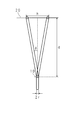
- FIG. 10A and 10B are schematic diagrams for explaining the configuration of the optical scanner according to Patent Document 1.
- FIG. 10A shows a curved mirror included in the optical scanner of Patent Document 1
- FIG. 10B shows a comparison.
- a first light deflection element 110 included in a conventional projection type image display apparatus is shown.
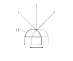
- the optical scanner according to Patent Document 1 includes a substantially hemispherical curved mirror 151, and the reflection angle of the incident laser beam can be changed by translating the curved mirror 151.
- the optical scanner according to Patent Document 1 reflects the laser beam in a larger angle range as compared with the change in the reflection angle caused by the rotation of the first light deflection element 110 provided in the conventional projection type image display device. Since the scanning angle by the laser beam can be enlarged, the image can be displayed larger.
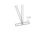
- FIG. 11A shows the incidence and reflection of the curved mirror 151 in the optical scanner of Patent Document 1
- FIG. FIG. 6 shows the incidence and reflection of the first light deflection element 110 of the conventional projection type image display device for comparison.
- three laser beams of red, green, and blue are incident as parallel light from the optical system 102 on the first light deflection element 110 of the conventional projection type image display apparatus. Since the mirror surface of the first light deflection element 110 is a flat surface, the parallel light incident as parallel light is reflected as parallel light.
- the curved mirror 151 since the mirror surface is a curved surface, the incident angle with respect to the mirror surface varies depending on the position where the laser beam is incident, and the reflection direction of the laser beam varies. Therefore, even when parallel light is incident on the curved mirror 151, the reflected laser light is not parallel light, and the spot diameter of the laser light projected on the screen is large, so that they are adjacent in the projected image. Laser light for displaying pixels overlaps and the projected image is blurred, causing a problem that display image quality is deteriorated.
- the present invention has been made in view of such circumstances, and an object of the present invention is to enlarge a scanning angle of a laser beam and project and display a larger image without deteriorating display image quality. It is an object of the present invention to provide a projection type image display apparatus that can do this.
- a projection-type image display apparatus is a projection-type image display apparatus that displays an image by deflecting light from a light source with a light deflection element and projecting the light.
- a first light deflection element having a shaft and deflecting light by reflecting light on the mirror surface rotated by the rotation shaft; and the mirror surface and the mirror surface are rotated in different directions.
- a second optical deflection element that has two pivot axes and deflects light by reflecting light on the mirror surface that pivots around the two pivot axes, and the first optical deflection element The first light deflecting element and the second light deflecting element are arranged so that the light reflected by the light enters the second light deflecting element.
- the projection type image display apparatus provides an image to be displayed by rotating the mirror surface of the first light deflection element and rotating the mirror surface by one rotation axis of the second light deflection element. Scanning in the horizontal direction is performed, and scanning of the image to be displayed is performed in the vertical direction by rotation of the mirror surface by the other rotation axis of the second light deflection element.
- the rotation of the mirror surface by the one rotation axis of the second light deflection element and the rotation of the mirror surface of the first light deflection element are in phase. It is made to be performed by.
- the projection type image display apparatus is characterized by comprising a plurality of the second light deflection elements.
- one rotation axis included in each of the plurality of second light deflection elements is arranged in parallel to each other, and the other rotation axes are arranged to coincide with each other. It is characterized by.
- a first light deflection element having at least one rotation axis and a second light deflection element having two rotation axes are used, and light from the light source is reflected by the first light deflection element.
- the projection type image display apparatus displays an image by making the light incident on the second light deflecting element and projecting the light reflected by the second light deflecting element.
- the scanning angle can be increased by rotating the second light deflection element with two rotation axes. For example, the horizontal scanning of the image is performed in the same phase by the rotation of the first light deflection element and the rotation of one rotation axis of the second light deflection element, and the other times of the second light deflection element.
- Scanning in the vertical direction of the image can be performed by rotation on the moving axis. Accordingly, since the horizontal scanning angle of the image in the projection type image display apparatus can be expanded without increasing the rotation angle of the first light deflection element, large image display and high image quality of the displayed image can be achieved. Both can be realized.
- the projection type image display device can be configured to include a plurality of second light deflection elements. At this time, even if a plurality of second light deflection elements are arranged by arranging one rotation axis for performing horizontal scanning of each second light deflection element in parallel and aligning the other rotation axes. Good. By providing a plurality of second light deflection elements, it is possible to reduce the size of each second light deflection element and increase the rotation speed as compared with the case where one second light deflection element is provided. Therefore, it is possible to realize further higher image quality of the displayed image.
- the first light deflection element having at least one rotation axis reflects the light from the light source to enter the second light deflection element, and the second light deflection element having two rotation axes is provided.
- the scanning angle of the projection-type image display device can be expanded without increasing the rotation angle of the first light deflection element. Therefore, since the rotation speed of the first light deflection element can be increased, high-quality image display can be performed, and a large image can be displayed by increasing the scanning angle.
- FIG. 10 is a schematic diagram illustrating a configuration of an optical scanner according to Patent Document 1.
- FIG. 10 is a schematic diagram illustrating a configuration of an optical scanner according to Patent Document 1.
- FIG. 10 is a schematic diagram for explaining problems of the optical scanner according to Patent Document 1.
- FIG. 10 is a schematic diagram for explaining problems of the optical scanner according to Patent Document 1.
- FIG. 10 is a schematic diagram for explaining problems of the optical scanner according to Patent Document 1.
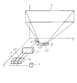
- FIG. 1 is a schematic diagram showing a configuration of a projection type image display apparatus according to Embodiment 1 of the present invention.
- reference numerals 1R, 1G, and 1B denote laser light sources that emit red, green, and blue laser lights, respectively, and light emission control is performed by the laser modulator 3.
- the laser modulation unit 3 is supplied with an image signal related to a display image, and controls the intensity of laser light of each color according to the image signal.
- the laser beams of the respective colors emitted from the laser light sources 1R, 1G, and 1B are incident on the optical system 2.
- the optical system 2 combines the three laser beams on the same optical axis by shaping the three laser beams from the laser light sources 1R, 1G, and 1B into laser beams that are substantially parallel and have a small beam diameter.
- the laser modulation unit 3 controls the intensity of the three laser beams, and the optical system 2 combines the three laser beams, so that the laser beam combined with the color of each pixel of the display image is transmitted from the optical system 2 to the first light.
- the light is emitted to the deflection element 10.
- the laser light emitted from the optical system 2 is deflected by the first light deflection element 10 and the second light deflection element 20 and projected onto the screen 5 as an image.
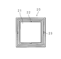
- FIG. 2A is a schematic diagram showing a configuration of the first light deflection element 10 of the projection type image display apparatus according to Embodiment 1 of the present invention.
- FIG. 2B is a schematic diagram showing the configuration of the second light deflection element 20 of the projection type image display apparatus according to Embodiment 1 of the present invention.
- the first light deflection element 10 has a mirror surface 11 that reflects laser light and at least one rotation shaft 12 that rotates the mirror surface 11 (see FIG. 2A).
- the second light deflection element 20 includes a mirror surface 21 that reflects laser light, a first rotation shaft 22 that rotates the mirror surface 21, and a mirror surface 21 that is substantially orthogonal to the first rotation shaft 22. And a second rotation shaft 23 for rotating the lens (see FIG. 2B).
- the rotation by the first rotation shaft 22 and the rotation by the second rotation shaft 23 can be performed independently.
- the rotation means an operation that swings around a rotation axis like a seesaw, that is, an operation that rotates forward and backward within a predetermined angle range of 360 ° or less.
- the projection type image display apparatus includes a light deflection element controller that rotates the mirror surfaces of the first light deflection element 10 and the second light deflection element 20 by any method.
- the element control unit controls the rotation speed and rotation direction of the mirror surface.
- the first light deflection element 10 is disposed at a position where the rotation axis 12 intersects the laser beam emitted from the optical system 2 at a predetermined angle smaller than 90 °. .
- the first rotation shaft 22 is substantially parallel to the laser light emitted from the optical system 2, and the first rotation shaft 22 and the rotation shaft 12 of the first light deflection element 10.
- Projection-type image display device so that the extension line of the second crossing axis intersects at a predetermined angle smaller than 90 ° and the second rotation shaft 23 is substantially perpendicular to the laser light emitted from the optical system 2. Is disposed. In other words, in FIG.
- the xy plane The first light deflection element 10 and the second light deflection element 20 so that the projected images of the rotation axis 12 of the first light deflection element 10 and the first rotation axis 22 of the second light deflection element 20 are in a straight line. Is arranged.
- the mirror surface 11 of the first light deflection element 10 is rotated by a rotation shaft 12, and light incident in the x direction in the figure is converted into light having a spread in the y direction, and the second light deflection element 10. Reflected to.
- the first light deflection element 10 performs (previous) scanning in the horizontal direction of the image projected on the screen 5.
- the light having a spread in the y direction emitted from the first light deflection element 10 is incident on the mirror surface 21 of the second light deflection element 20.
- the mirror surface 21 of the second light deflection element 20 is rotated by the first rotation shaft 22, and the light from the first light deflection element 10 is converted into light having a further spread in the y direction to the screen 5.
- the second light deflection element 20 performs (rear) scanning in the horizontal direction of the image projected on the screen 5. That is, the projection-type image display apparatus according to the present invention performs horizontal scanning using not only the first light deflection element 10 but also both the first light deflection element 10 and the second light deflection element 20.
- the rotation of the first light deflection element 10 and the rotation of the second light deflection element 20 by the first rotation shaft 22 are performed in the same phase. That is, when the rotation of the first light deflection element 10 reaches the one end side, the rotation of the second light deflection element 20 also reaches the one end side and reflects the light to the one end side of the screen 5. When the rotation of the deflection element 10 reaches the center position, the rotation of the second light deflection element 20 also reaches the center position, reflects light to the center position of the screen 5, and rotates the first light deflection element 10.
- the rotation of the first light deflection element 10 is such that the rotation of the second light deflection element 20 also reaches the other end side and reflects the light to the other end side of the screen 5.
- the movement and the rotation of the second light deflection element 20 by the first rotation shaft 22 are adjusted in rotation speed, rotation direction, rotation timing, and the like.
- the mirror surface 21 of the second light deflecting element 20 is rotated by the second rotating shaft 23, and the light from the first light deflecting element 10 is converted into light having a spread in the z direction, and the screen 5. Reflected to. Thereby, scanning in the vertical direction of the image projected on the screen 5 is performed by the second light deflection element. That is, in the projection type image display apparatus according to the present invention, the second light deflection element 10 performs scanning in both the horizontal direction and the vertical direction. Therefore, the projection type image display apparatus can perform scanning in the horizontal direction and the vertical direction by the first light deflection element 10 and the second light deflection element 20, and projects and displays a substantially rectangular image on the screen 5. Can do.
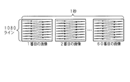
- FIG. 3 is a schematic diagram for explaining image display by the projection-type image display device, and schematically shows a configuration of an image (moving image) projected on the screen 5.
- the projection-type image display device scans the laser beam sequentially from top to bottom while repeating the screen 5 from left to right and from right to left in order, so that the human eye receives the two-dimensional laser beam due to the afterimage effect. It is recognized as an image, and one image can be formed on the screen 5.
- the scanning of the screen 5 from left to right and from right to left is realized by the rotation of the first light deflection element 10 and the rotation of the second light deflection element 20 by the first rotation shaft 22. Further, the scanning from the top to the bottom of the screen 5 is realized by the rotation of the second light deflection element 20 by the second rotation shaft 23.
- the projection type image display apparatus includes an optical deflection element control unit that controls the rotation of the first optical deflection element 10 and the second optical deflection element 20, and the rotational speed and the rotational direction by the optical deflection element control unit. By changing the control, etc., the scanning order of the laser light can be changed.
- the projection-type image display device includes an image signal processing unit (not shown) that receives an image signal related to an image to be displayed and converts the input image signal in accordance with the scanning order of the laser light.
- the image signal processing unit converts the image signal by rearranging the information of each pixel included in the input image signal in the scanning order of the laser light, and gives the converted image signal to the laser modulation unit 3.
- the image signal processing unit appropriately converts the image signal in accordance with the scanning order of the laser light by the first light deflecting element 10 and the second light deflecting element 20, so that the projection type can be used regardless of the order of scanning of the laser light.
- the image display apparatus can appropriately perform image display.
- the projection type image display device displays a high-definition image of 1920 ⁇ 1080 60 times per second to display a moving image
- the enlargement of the rotation angle of the first light deflection element 110 and the increase of the rotation speed are in a trade-off relationship, and the display image quality is improved. It is difficult to realize both the image size enlargement and the image size enlargement.
- the projection type image display apparatus is configured to perform horizontal scanning using the two light deflecting elements, the first light deflecting element 10 and the second light deflecting element 20, so that the first Even if the rotation angle and rotation speed of the light deflection element 10 are the same as the conventional one, the second light deflection element 20 can enlarge the scanning angle in the horizontal direction. Note that the vertical scanning is performed only by the rotation of the second light deflection element 20, but the vertical rotation only needs to be performed 60 times per second, so that the scanning angle can be easily expanded.
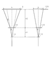
- FIG. 4 is a schematic diagram for explaining the scanning angle of the laser beam in the horizontal direction.
- the left side of FIG. 4 shows the case of the projection type image display apparatus according to the present invention, and the right side shows a conventional one for comparison.
- the case of a projection type image display apparatus is shown.
- the distance from the first light deflection element 10 (110) to the second light deflection element 20 (120) is d1
- the distance from the second light deflection element 20 (120) to the screen 5 (105) is the distance.
- the horizontal scanning angle of the laser light by the first light deflection element 10 (110) is ⁇
- the horizontal scanning angle of the laser light by the second light deflection element 20 is ⁇ .
- the laser light from the optical system 2 is spread by a scanning angle of ⁇ ⁇ in the horizontal direction by the first light deflection element 10 (110) and is incident on the second light deflection element 20 (120).
- the second light deflection element 120 does not contribute to the horizontal scanning, and therefore the light is projected onto the screen 105 with a spread of ⁇ ⁇ in the horizontal direction (see the right side in FIG. 4).
- the width h in the horizontal direction of the image projected on the screen 105 is expressed by the following (Formula 1).
- h 2 ⁇ (d1 + d2) ⁇ tan ⁇ (Expression 1)
- the light emitted from the first light deflection element 10 is further expanded by the scanning angle of ⁇ ⁇ in the horizontal direction by the second light deflection element 20 and projected onto the screen 5. (See the left side of FIG. 4).
- the projection type image display apparatus according to the present invention can display a large image having a width approximately twice as large as that of the conventional projection type image display apparatus.
- the first light deflection element 10 having one rotating shaft 12 scans the laser beam from the optical system 2 in the horizontal direction and the second light deflection element.
- the first light deflection element 20 is configured such that the second light deflection element 20 having two rotation shafts 22 and 23 scans the light in the horizontal direction and the vertical direction and projects the light onto the screen 5.
- the scanning angle in the horizontal direction can be expanded without increasing the 10 rotation angle. Therefore, the rotation speed of the first light deflection element 10 can be increased, high-quality image display can be performed, and a large image can be displayed by increasing the scanning angle.
- the first light deflection element 10 is rotated at a low speed and a wide angle
- the second light deflection element 20 is rotated at a low speed and a wide angle by the first rotation shaft 22
- the second light deflection element 20 can be rotated at a high speed and a narrow angle by the second rotation shaft 23.
- the projection type image display apparatus can display a long image in the horizontal direction.
- the projection-type image display apparatus according to the present invention appropriately controls the rotation of the first light deflection element 10 and the rotation of the second light deflection element 20 by the two rotation axes. It is possible to display an image having a size or shape that is not easy to display with a conventional projection image display apparatus.
- FIG. 5 is a schematic diagram showing a configuration of a projection type image display apparatus according to Embodiment 2 of the present invention.
- the laser light sources 1R, 1G, and 1B, the optical system 2, and the laser modulation unit 3 included in the projection image display apparatus are not shown.
- FIG. 6 is a schematic diagram showing the configuration of the second light deflection element of the projection type image display apparatus according to Embodiment 2 of the present invention.
- the projection type image display apparatus includes one first light deflection element 10 and three second light deflection elements 20a to 20c.
- the three second light deflection elements 20a to 20c are arranged side by side in a direction substantially perpendicular to the laser light from the optical system 2 (y direction), and have mirror surfaces 21a to 21c that reflect the laser light, respectively.
- the mirror surfaces 21a to 21c can be independently rotated by first rotating shafts 22a to 22c arranged substantially in parallel, and are common to the first rotating shafts 22a to 22c.
- the second rotation shaft 23 can be rotated together. Note that the rotation of the mirror surfaces 21a to 21c by the first rotation shafts 22a to 22c is performed in the same direction and in the same phase.
- the laser light from the optical system 2 is reflected by the first light deflecting element 10 as light having a spread in the y direction (scanned in the horizontal direction) and enters the second light deflecting elements 20a to 20c.
- the light reflected by the first light deflection element 20 is incident on any one of the three second light deflection elements 20 a to 20 c in accordance with the rotational position of the first light deflection element 10.
- the light incident on the second light deflecting element 20a disposed on the left side is reflected to the left side of the screen 5 to form the left part of the image, and is disposed in the center.
- the light incident on the second light deflection element 20b forms the central portion of the image reflected at the center of the screen 5, and the light incident on the second light deflection element 20c disposed on the right side is reflected on the right side of the screen 5. To form the right part of the image. As a result, one large image is formed on the screen 5 in the horizontal direction.
- the projection type image display apparatus includes a plurality of second light deflection elements 20a to 20c, so that the projection type image display apparatus includes one second light deflection element 20 (see Embodiment 1) having a large size.
- the rotation of the second light deflection element in the horizontal direction can be further accelerated.
- FIG. 7 is a schematic diagram for explaining the relationship between the spot radius of the laser light and the size of the second light deflection element 20, and the laser light from the optical system 2 is reflected by the first light deflection element 10. 1 to the second light deflection element 20 are schematically shown.
- FIG. 7 is a schematic diagram for explaining the relationship between the spot radius of the laser light and the size of the second light deflection element 20, and the laser light from the optical system 2 is reflected by the first light deflection element 10. 1 to the second light deflection element 20 are schematically shown.
- FIG. 7 is a schematic diagram for explaining the relationship between the spot radius of the laser light and the size of the second light deflection element 20, and the laser light
- the distance from the first light deflection element 10 to the second light deflection element 20 is d, and the laser light from the optical system 2 is reflected by the first light deflection element 10 with a spread of ⁇ ⁇ . It is assumed that r is the spot radius of the laser beam incident on the first light deflection element 10 from the optical system 2.
- the spread (horizontal width) h of the laser light in the second light deflection element 20 is expressed by the following (Equation 3).
- the resonance frequency increases as the size of the optical deflection element decreases. Therefore, by reducing the size of the light deflection element, the rotation of the light deflection element can be speeded up, and higher-definition image display is possible.
- the projection type image display apparatus is configured to include a plurality of second light deflection elements 20a to 20c, the size of each of the second light deflection elements 20a to 20c can be reduced. Accordingly, the plurality of second light deflecting elements 20a to 20c having a smaller size can rotate at a higher speed than the one second light deflecting element 20 having a larger size, so that the projection type image display according to the second embodiment is performed.
- the apparatus can perform higher-definition image display.
- the projection type image display apparatus includes three second light deflection elements 20a to 20c.
- the present invention is not limited to this, and two or four or more second light deflection elements are used. May be provided.
Landscapes
- Physics & Mathematics (AREA)
- Optics & Photonics (AREA)
- Engineering & Computer Science (AREA)
- Multimedia (AREA)
- Signal Processing (AREA)
- General Physics & Mathematics (AREA)
- Mechanical Optical Scanning Systems (AREA)
Applications Claiming Priority (2)
| Application Number | Priority Date | Filing Date | Title |
|---|---|---|---|
| JP2008122541A JP2009271375A (ja) | 2008-05-08 | 2008-05-08 | 投影型画像表示装置 |
| JP2008-122541 | 2008-05-08 |
Publications (1)
| Publication Number | Publication Date |
|---|---|
| WO2009136588A1 true WO2009136588A1 (ja) | 2009-11-12 |
Family
ID=41264643
Family Applications (1)
| Application Number | Title | Priority Date | Filing Date |
|---|---|---|---|
| PCT/JP2009/058475 Ceased WO2009136588A1 (ja) | 2008-05-08 | 2009-04-30 | 投影型画像表示装置 |
Country Status (2)
| Country | Link |
|---|---|
| JP (1) | JP2009271375A (enExample) |
| WO (1) | WO2009136588A1 (enExample) |
Cited By (1)
| Publication number | Priority date | Publication date | Assignee | Title |
|---|---|---|---|---|
| CN110018778A (zh) * | 2017-11-22 | 2019-07-16 | 佳能株式会社 | 通信设备、显示设备及其控制方法、存储介质和显示系统 |
Citations (2)
| Publication number | Priority date | Publication date | Assignee | Title |
|---|---|---|---|---|
| JP2004517351A (ja) * | 2000-11-03 | 2004-06-10 | マイクロビジョン インコーポレイテッド | 周波数調整可能の共振型走査装置及び調整可能にする方法 |
| JP2007163817A (ja) * | 2005-12-14 | 2007-06-28 | Canon Inc | 光偏向器、及びそれを用いた光学機器 |
Family Cites Families (1)
| Publication number | Priority date | Publication date | Assignee | Title |
|---|---|---|---|---|
| JPS5397447A (en) * | 1977-02-04 | 1978-08-25 | Canon Inc | Optical scanning system |
-
2008
- 2008-05-08 JP JP2008122541A patent/JP2009271375A/ja active Pending
-
2009
- 2009-04-30 WO PCT/JP2009/058475 patent/WO2009136588A1/ja not_active Ceased
Patent Citations (2)
| Publication number | Priority date | Publication date | Assignee | Title |
|---|---|---|---|---|
| JP2004517351A (ja) * | 2000-11-03 | 2004-06-10 | マイクロビジョン インコーポレイテッド | 周波数調整可能の共振型走査装置及び調整可能にする方法 |
| JP2007163817A (ja) * | 2005-12-14 | 2007-06-28 | Canon Inc | 光偏向器、及びそれを用いた光学機器 |
Cited By (2)
| Publication number | Priority date | Publication date | Assignee | Title |
|---|---|---|---|---|
| CN110018778A (zh) * | 2017-11-22 | 2019-07-16 | 佳能株式会社 | 通信设备、显示设备及其控制方法、存储介质和显示系统 |
| CN110018778B (zh) * | 2017-11-22 | 2023-05-12 | 佳能株式会社 | 通信设备、显示设备及其控制方法、存储介质和显示系统 |
Also Published As
| Publication number | Publication date |
|---|---|
| JP2009271375A (ja) | 2009-11-19 |
Similar Documents
| Publication | Publication Date | Title |
|---|---|---|
| US6971748B2 (en) | High-resolution display including pixel moving optical system | |
| US6781731B2 (en) | Micromirror device and projector employing the same | |
| EP1674914B1 (en) | Optical scanning device and image display apparatus | |
| JP4266660B2 (ja) | 投射型表示光学系および投射型画像表示装置 | |
| JP5091112B2 (ja) | 画像投射装置 | |
| US7753531B2 (en) | Image display apparatus and projection optical system | |
| US20070296645A1 (en) | Display apparatus using laser and method of using the same | |
| JP2005352488A (ja) | 走査角拡大光学システム及びそれを備えたスキャニング装置 | |
| JP2019039995A (ja) | 画像投射装置 | |
| JP4298455B2 (ja) | 走査型画像表示装置 | |
| US7810933B2 (en) | Image projection apparatus | |
| CN112394605B (zh) | 一种扫描投影方法、拼接式的扫描投影装置及设备 | |
| JP4036340B2 (ja) | ディスプレイ装置およびその走査方法 | |
| JP4095428B2 (ja) | 光走査光学系、画像投影装置、画像表示システム | |
| JP4264570B2 (ja) | 偏向装置を用いた投影型映像表示装置 | |
| WO2009136588A1 (ja) | 投影型画像表示装置 | |
| JP2010266824A (ja) | 画像表示装置 | |
| KR20030030226A (ko) | 가동 미러 장치 및 이를 채용한 프로젝터 | |
| JP4967573B2 (ja) | 画像投影装置 | |
| JP5287695B2 (ja) | 光偏向装置、光偏向アレー、画像投影表示装置 | |
| JP2008191466A (ja) | 投射型表示装置 | |
| JP5573005B2 (ja) | 画像表示装置、電子機器 | |
| US20090141191A1 (en) | Scanning image display and scanning image display system | |
| JP4170663B2 (ja) | 光走査装置 | |
| JP2001100147A (ja) | 投影型表示装置 |
Legal Events
| Date | Code | Title | Description |
|---|---|---|---|
| 121 | Ep: the epo has been informed by wipo that ep was designated in this application |
Ref document number: 09742712 Country of ref document: EP Kind code of ref document: A1 |
|
| DPE1 | Request for preliminary examination filed after expiration of 19th month from priority date (pct application filed from 20040101) | ||
| NENP | Non-entry into the national phase |
Ref country code: DE |
|
| 122 | Ep: pct application non-entry in european phase |
Ref document number: 09742712 Country of ref document: EP Kind code of ref document: A1 |