WO2009125481A1 - 画面表示システム及び画面表示プログラム - Google Patents
画面表示システム及び画面表示プログラム Download PDFInfo
- Publication number
- WO2009125481A1 WO2009125481A1 PCT/JP2008/057071 JP2008057071W WO2009125481A1 WO 2009125481 A1 WO2009125481 A1 WO 2009125481A1 JP 2008057071 W JP2008057071 W JP 2008057071W WO 2009125481 A1 WO2009125481 A1 WO 2009125481A1
- Authority
- WO
- WIPO (PCT)
- Prior art keywords
- screen
- user
- small screen
- line
- sight
- Prior art date
Links
Images


Classifications
-
- G—PHYSICS
- G06—COMPUTING; CALCULATING OR COUNTING
- G06F—ELECTRIC DIGITAL DATA PROCESSING
- G06F3/00—Input arrangements for transferring data to be processed into a form capable of being handled by the computer; Output arrangements for transferring data from processing unit to output unit, e.g. interface arrangements
- G06F3/01—Input arrangements or combined input and output arrangements for interaction between user and computer
- G06F3/011—Arrangements for interaction with the human body, e.g. for user immersion in virtual reality
-
- G—PHYSICS
- G06—COMPUTING; CALCULATING OR COUNTING
- G06F—ELECTRIC DIGITAL DATA PROCESSING
- G06F3/00—Input arrangements for transferring data to be processed into a form capable of being handled by the computer; Output arrangements for transferring data from processing unit to output unit, e.g. interface arrangements
- G06F3/01—Input arrangements or combined input and output arrangements for interaction between user and computer
- G06F3/048—Interaction techniques based on graphical user interfaces [GUI]
- G06F3/0481—Interaction techniques based on graphical user interfaces [GUI] based on specific properties of the displayed interaction object or a metaphor-based environment, e.g. interaction with desktop elements like windows or icons, or assisted by a cursor's changing behaviour or appearance
Definitions
- the present invention relates to a technique for displaying a screen, and is particularly applicable to a screen display system and a screen display program for displaying a small screen on a large display.
- the large display is a convenient tool that can display information to a large number of audiences at the same time, but it is even more convenient if each individual audience can interact and operate to display information according to individual operations on the large display. It is.
- the present invention has been made in view of the above circumstances, and as an example of the problem, when displaying a small screen on a large display, the user does not feel troublesome in operation, and system maintenance is performed.
- An object is to provide an easy screen display system and a screen display program.
- the invention according to claim 1 is directed to display means having an image display surface of a first size, and a user's line-of-sight position existing in a predetermined area in front of the image display surface.
- a processing means is directed to display means having an image display surface of a first size, and a user's line-of-sight position existing in a predetermined area in front of the image display surface.
- the invention according to claim 14 is a computer-readable screen display program for displaying information on a display means having an image display surface of a first size, and a predetermined area in front of the image display surface.
- a position detecting step for detecting the user's line-of-sight position existing in the second position, and a second size smaller than the first size on the image display surface in accordance with the user's line-of-sight position detected in the position detecting step.
- a screen display program for causing the computer to execute a screen processing step for displaying a small-sized screen.
- FIG. 1 is a diagram showing an overview configuration of a small screen display system (hereinafter abbreviated as a small screen display system) 100 using a large display according to an embodiment of the present invention.
- the small screen display system 100 includes, for example, a display device 1 having a large screen 11 exceeding 100 inches, a sensor device 2 that detects a user H in a detection range S in front of the large screen 11, and use of the sensor device 2. And a display control device 3 that generates and displays a small screen 7 for each user H on the large screen 11 of the display device 1 in accordance with the mode of person detection. Accordingly, the optimum small screen 7 is displayed at the optimum position.
- the display control device 3 is connected to the sensor device 2, a position detection device 4 that detects the position of the user H, a storage device 5 that stores various information for displaying the small screen 7, and the display device 1. And a screen processing device 6 for displaying the small screen 7 on the large screen 11 or erasing the small screen 7 displayed on the large screen 11 according to the position detection status by the position detecting device 4. It is equipped with.
- the form of the display control device 3 may be either a physically configured device or a system configuration in which a plurality of devices are connected to a network.
- FIG. 2 is a functional configuration diagram of the small screen display system 100 shown in FIG.
- the small screen display system 100 includes a position detection unit 10, a storage unit 20, and a screen processing unit 30, which are roughly divided in terms of functions.
- the position detection unit 10 includes a sensor device 2 and a position detection device 4.
- the sensor device 2 may be any non-contact type sensor device that can detect the presence of the user H in the detection range S and the three-dimensional position of the existing user H.
- an infrared sensor 8 and an ultrasonic sensor 9 are arranged on the ceiling above the detection range S, and the use existing in the detection range S is used.
- the person H can be monitored. That is, the infrared sensor 8 and the ultrasonic sensor 9 are arranged at equal intervals in a grid pattern immediately above the detection range S, and irradiate infrared rays and ultrasonic waves downward to detect objects existing in the detection range S.
- the infrared sensor 8 detects the two-dimensional position (xy coordinates) of the detected object (user H), and the ultrasonic sensor 9 detects the three-dimensional position (the user H) of the detected object (user H). xyz coordinates).
- the arrangement density may be lower than that of the ultrasonic sensor 9.
- the position detection device 4 performs position detection processing using information detected by the sensor device 2.
- the position detection process in the present embodiment is roughly divided into a range detection process P10 and a detailed position detection process P20.
- the range detection process P10 is a process of operating the infrared sensor 8 and detecting a rough range in which an object exists based on information acquired by the infrared sensor 8.
- the detailed position detection process P20 receives the result of the range detection process P10, operates the ultrasonic sensor 9, and based on the information acquired by the ultrasonic sensor 9, the object detected in the range detection process P10 is detected. This is a process for determining whether or not the user is a person and, if the person is a person, calculating the line-of-sight position of the user H.
- the storage unit 20 is composed of the storage device 5 and stores various information for displaying the small screen 7. Specifically, the storage unit 20 uses the structure array A that manages the line-of-sight position of each user H in the detection range S, the display position of each small screen 7 that is displayed, and the use that is viewing the small screen 7. Information such as a structure array B that manages the person H, a new person ID that manages a person who has started watching, and an erasure person ID that manages a person who has finished watching are stored.
- the structure array A manages information related to the user H.
- the person ID that can uniquely identify the user H (denoted as HID), the line-of-sight position of the user H (represented by three-dimensional coordinates, EL (Denoted as (x, y, z)), and a structure array having a person ID use flag (denoted as HIDF) indicating whether or not the data of the sequence number is used as a constituent element.
- the array element number of the structure array A is used as the HID, and HIDF is set to 1 when the data of the array element number is used, and 0 when not used. It has become so.
- the structure array B manages information related to the small screen 7 to be displayed, the small screen ID that can uniquely identify the small screen 7 (denoted as DID), and the display position of the small screen 7 (in two-dimensional coordinates).
- DL (dx, dz)) the person ID of the person watching the small screen 7 (denoted as WID)
- WID the person ID of the person watching the small screen 7
- WID the display position of the small screen 7
- the array element number of the structure array B is used as DID
- DIDF is set to 1 when the data of the array element number is used, and 0 when not used.
- the new person ID is information recorded when the user H who has newly started viewing is detected in the processing of the position detection unit 10, and the person ID (HID) of the user H is the new person ID (NewHID). It is set as).
- the erasure person ID is information recorded when the user H who has finished viewing is detected in the processing of the position detection unit 10, and the person ID (HID) of the user H is expressed as an erasure person ID (DelHID). To be set).
- the screen processing unit 30 includes a screen processing device 6 and a display device 1.
- the screen processing device 6 is displayed on the screen display processing P30 for displaying the small screen 7 on the large screen 11 of the display device 1 and the large screen 11 of the display device 1 according to the position detection situation in the position detection unit 10.
- a screen erasure process P40 for erasing the small screen 7 is executed.
- the screen display process P30 is a process of displaying the small screen 7 at the detected line-of-sight position of the user H when the user H who has newly started viewing is detected in the process of the position detection unit 10. However, when the small screen 7 is already displayed in the vicinity, or when a plurality of users H appear at almost the same time, the new small screen 7 is not displayed or a plurality of already displayed small screens 7 are displayed. It is displayed again at a position suitable for the human user H. Such display control of the screen display process P30 will be described in detail later.
- the screen erasure process P40 is a process of erasing the small screen 7 viewed by the user H when the user H who has finished viewing is detected in the process of the position detection unit 10. However, in the case where the other user H is also viewing the small screen 7 that the user H was viewing, the small screen 7 is placed at a position suitable for the other user H without deleting the small screen 7. It is supposed to redisplay. Such display control of the screen erasing process P40 will be described later in detail.
- the small screen display system 100 includes a central processing unit (CPU) having at least a calculation / control function, a main storage device (ROM, RAM, etc. having a storage function for storing programs and data). Memory) and an auxiliary storage device such as a hard disk.
- CPU central processing unit
- main storage device ROM, RAM, etc. having a storage function for storing programs and data
- Memory auxiliary storage device
- the position detection unit 10 and the screen processing unit 30 are nothing but a calculation / control function in the small screen display system 100
- the storage unit 20 is nothing but a specific example of the storage function in the small screen display system 100.
- a program for executing various processes according to the present embodiment is the main storage device or the hard disk described above.
- FIGS. 4 is a flowchart showing a flow of the range detection process P10 in the position detection unit 10 of the small screen display system 100
- FIG. 5 is a detailed position detection process P20 in the position detection unit 10 of the small screen display system 100. It is a flowchart which shows the flow.
- 6 is a flowchart showing the flow of the screen display processing P30 in the screen processing unit 30 of the small screen display system 100
- FIG. 7 shows the flow of the screen erasing processing P40 in the screen processing unit 30 of the small screen display system 100. It is a flowchart which shows.
- the range detection process P ⁇ b> 10 is a process for detecting a rough position where an object is present, and is always operating in the position detection unit 10.
- the position detection device 4 acquires the value of the entire detection range S from the infrared sensor 8 every period dt1 (step S10).
- the position detection device 4 determines whether or not there is an object looking at the large screen 11 from the acquired value (step S20). Specifically, from the acquired value of the infrared sensor 8, the temperature T1 ( An object having an area of S1 (a value close to the area occupied by a human being) having a heat greater than or equal to the human body temperature is detected, and this object is almost moved. (Specifically, it is determined from a change in the position of the object detected every period dt1). That is, in the present embodiment, when an object having an area of S1 or more is detected with heat equal to or higher than the temperature T1, and the object hardly moves, it is determined that the object is looking at the large screen 11. .
- step S20 If it is determined that there is an object looking at the large screen 11 (step S20: YES), the position detection device 4 calculates the area s1 of the range a1 occupied by the object (step S30), and then the detailed position detection The process P20 is generated, the range a1 and the area s1 are passed as arguments (step S40), and the process returns to step S10. On the other hand, if it is determined that there is no object looking at the large screen 11 (step S20: NO), the process returns to step S10.
- step S20 when an object looking at a plurality of large screens 11 at the same time is detected, a plurality of detailed position detection processes P20 are generated according to each object and operated in parallel.
- step S20 in the subsequent range detection process P10 when the object looking at the large screen 11 is detected, the infrared sensor 8 is not operated in the range a1 in order to prevent the object from being detected again. Like that.
- the detailed position detection process P20 is a process of determining whether or not the object detected in the range detection process P10 is a person and, if it is a person, calculating the line-of-sight position of the person, It is activated by an instruction from the range detection process P10.
- the position detection device 4 upon receiving the range a1 and the area s1 (see step S40) from the range detection process P10, the position detection device 4 operates the ultrasonic sensor 9 in the range a1 (step S110), and the range a1 from the ultrasonic sensor 9 is detected. The value at is acquired, and the three-dimensional shape of the object is detected (step S120).
- the position detection device 4 performs matching between the detected three-dimensional shape of the object and a pre-registered human shape pattern, and determines whether or not the detected three-dimensional shape of the object is a human shape.
- This determination process is a process for eliminating malfunctions of objects other than humans (for example, animals).
- the human shape pattern means, for example, a plurality of patterns related to the assumed posture of the person such as standing, leaning forward, sitting on the ground, and the like. Are previously registered in the position detection device 4. As described above, by holding patterns related to a plurality of human postures, it is possible to detect a person in various body shapes and postures such as an elderly person with a bent hip as well as a person in an upright posture.
- exclusion patterns for example, posture patterns of animals such as dogs and cats
- a function for determining whether or not to match the exclusion pattern is added. It may be determined that the three-dimensional shape is not a human shape. In this case, malfunctions with respect to objects other than humans can be further reduced.
- the position detection device 4 uses the center position (x1, y1) on the xy plane of the user H and the usage.
- the height z1 of the person H is detected (step S140), and then the eye height z2 is calculated from the height z1 of the user H (step S150).
- the height z1 of the user H is the height of the top of the head, it is necessary to correct z1 in order to calculate the eye gaze position.
- the position of the eye is approximately in the center of the head length
- the head length is calculated from the difference between the height of the head of the head and the height of the shoulder detected from the three-dimensional shape.
- the eye height z2 is calculated by subtracting a value Z1 obtained by dividing it by 2 (for example, if the length of the head is approximately 20 cm, Z1 is approximately 10 cm).
- a correction value table corresponding to the height of the top of the head is created, and the eye height is calculated using the correction value table. Also good.
- the calculated line-of-sight coordinates (x1, y1, z2) of the user H is set in the line-of-sight position EL (x, y, z) of the data, and HIDF is set to 1 and updated (step S170).
- the line of sight of the N1th data of the structure array A (X1, y1, z2) is set in the position EL, 1 is set in the HIDF, and the data is updated.
- the position detection device 4 sets the HID (array number) of the user H to the new ID (NewHID) of the storage device 5 (step S170), and generates the screen display processing P30 for the screen processing device 6. (Step S180). For example, when the line-of-sight position EL is updated with respect to the N1th data in the structure array A, N1 is set in NewHID and recorded in the storage device 5. As a result, the screen processing device 6 can grasp to whom the small screen 7 should be newly displayed in the screen display processing P30 described later. In addition, since an initialization process is performed when recording a new person ID in the storage device 5, the element corresponding to the new person ID recorded so far is cleared.
- the position detection device 4 calculates the volume v1 occupied by the user H at every time interval dt2 based on the three-dimensional shape of the user H (step S190). This is a process for monitoring whether or not the user H has left the large screen 11 (small screen 7) after the position of the user H is detected.
- the position detection device 4 determines whether or not a person has moved from the change in the calculated volume v1 (step S200). Specifically, if the change in volume v1 is large, for example, if the rate of decrease in volume v1 is greater than a predetermined threshold, it is determined that the person has left the viewing position, otherwise the person remains in the viewing position. It is determined that the user is looking at the small screen 7.
- the position detection device 4 determines that the user H has stopped viewing the small screen 7, and erases the storage device 5.
- the HID of the user H is set in the person ID (DelHID)
- the screen processing device 6 is instructed to generate the screen erasing process P40 (step S210), and the process ends.
- the HID sequence number
- N1 is set in DelHID and recorded in the storage device 5.
- the screen processing device 6 can grasp which small screen 7 should be erased in the screen erase process P40 described later.
- step S190 is repeated.
- step S130 when it is determined from the three-dimensional shape of the detected object that the object is not a person (step S130: NO), the position detection device 4 stops the ultrasonic sensor 9 that has been operating in the range a1 (Ste S220). Furthermore, regarding the range a1, the ultrasonic sensor 9 is locked so that the ultrasonic sensor 9 is not operated from another detailed position detection process P30. This is to prevent a non-human object from being detected many times.
- the position detection device 4 determines whether or not the detected object has moved (step S230). Specifically, in the range a1, the area s2 of the portion having the temperature T1 or higher has changed significantly compared to the initial area s1, for example, when the area s2 is significantly smaller than the area s1, the detected object moves. Judge that it was done.
- step S230 When the detected object moves (step S230: YES), the position detection device 4 releases the locked ultrasonic sensor 9 and enables the ultrasonic sensor 9 to operate in the range a1 (step S240). The process ends. This is because another object may come to the point, so that the other object can be detected. On the other hand, when the detected object has not moved (step S230: NO), the process of step S230 is repeated.
- the screen display process P30 is a process for displaying the small screen 7 at the line-of-sight position of the user H newly detected by the position detection unit 10, and is activated by an instruction from the detailed position detection process P20.
- the screen processing device 6 reads the new person ID (NewHID) recorded in the storage device 5, and acquires the line-of-sight position EL of the corresponding data from the structure array A according to the read new person ID (step S310).
- NewHID is N1
- the line-of-sight position EL of the N1th data in the structure array A is (x3, y3, z3).
- the screen processing device 6 determines whether there is another small screen 7 in the vicinity of the position (x3, z3) where the small screen 7 is to be displayed (step S320). This is because, if the small screen 7 is displayed in the vicinity of (x3, z3), if a new small screen 7 is displayed in the vicinity of the small screen 7, it will be inconvenient and inappropriate. This determination is performed so that 7 is not displayed. Specifically, it is determined by referring to the display position DL of the structure array B whether another small screen 7 exists within a predetermined radius R1 from the position (x3, z3).
- the screen processing device 6 When there is no other small screen 7 in the vicinity of the position (x3, z3) where the small screen 7 is to be displayed (step S320: NO), the screen processing device 6 is the position (x3) where the small screen 7 is to be displayed. , Z3), the small screen 7 is displayed (step S350).
- the screen processing device 6 displays a small screen 7 of about 12 inches with x3 as the center in the x-axis direction and z3 as the upper limit in the z-axis direction. That is, the user H can see the small screen 7 in a slightly downward attitude.
- the position (x3, z3) at which the small screen 7 is displayed is set in the display position DL, NewHID is set in WID, the current time is set in DT, 1 is set in DIDF, and the data is updated ( Step S370), the process is terminated.
- the display of the N2nd data of the structure array B (X3, z3) is set in the position DL, NewHID is set in the WID, the current time is set in the DT, and 1 is set in the DIDF to update the data.
- step S320 when there is another small screen 7 in the vicinity of the position (x3, z3) at which the small screen 7 is to be displayed (step S320: YES), the structure array B is referred to and the small screen 7 at the closest position is referred to.
- the display position DL (dx, dz) of the screen 7 (hereinafter referred to as the closest small screen 7) is acquired (step S330), the z coordinates dz and z3 of the closest small screen 7 are compared, and the difference is equal to or greater than Z2. Whether or not (step S340).
- the DID of the closest small screen 7 is N3 and the display position DL is (dxN3, dzN3), it is determined whether or not the difference between z3 and dzN3 is greater than or equal to Z2. This is different depending on the height when the xy position is substantially the same or close, but the z position is too far away (for example, when a child tries to see a small screen 7 viewed by an adult). Since it is better to display the small screen 7, it is determined whether or not this is the case.
- step S340 YES
- the screen processing device 6 displays a new small screen 7.
- Steps S350 to S370 described above are executed. As a result, the newly appearing user H can see the newly displayed small screen 7.
- step S380 it is determined whether or not a certain time TT1 has elapsed since the closest small screen 7 was displayed (step S380). ). This is because the small screen 7 is displayed in accordance with the line of sight of the user H first detected among the plurality of users in the small screen display when the plurality of users H appear in the detection range S substantially simultaneously. This determination is performed in order to prevent this.
- TT1 is set to a value of about several seconds. The time since the closest small screen 7 was displayed is calculated from DT and the current time.
- step S380 When a certain time TT1 or more has elapsed since the closest small screen 7 was displayed (step S380: YES), the screen processing device 6 does not correct the position of the closest small screen 7 and starts from the structure array B. Then, the data having the DID of the closest small screen 7 is acquired, the NewHID is added to the WID of the data, and the data is updated (step S410). For example, when the DID of the closest small screen 7 is N3, NewHID is added to the WID of the N3rd data in the structure array B to update the data.
- the screen processing device 6 When another user H comes near the closest small screen 7 after a long time has passed since the closest small screen 7 is displayed, the screen processing device 6 The display is continued as it is without changing the position of the closest small screen 7 displayed for the user H.
- the screen processing device 6 reads the closest small screen 7 from the structure array B.
- Obtain data having DID refer to the person IDs of all the people who are viewing the closest screen 7 from the WID of the data, refer to the structure array A based on the referred person ID
- the average value of the x-coordinate and z-coordinate of the line-of-sight position EL of all the people watching the close-up screen 7 is calculated (step S390).
- the average of the x-coordinates of the line-of-sight positions EL of all the people watching the closest screen 7 is xav1, and the average of the z-coordinates is zav1.
- the screen processing device 6 displays the small screen 7 at (xav1, zav1), acquires data having the DID of the closest small screen 7 from the structure array B, and displays the data at the display position DL of the data ( xav1, zav1) are set (step S400), and NewHID is added to the WID to update the data (step S410).
- the DID of the closest small screen 7 is N3
- (xav1, zav1) is set to the display position DL of the N3rd data in the structure array B
- NewHID is added to the WID to update the data To do.
- the screen processing device 6 calculates the average position of the line of sight of a plurality of users H, and moves the closest small screen 7 to the calculated average position. indicate.
- the screen erasure process P40 is a process of erasing the small screen 7 that the user H was viewing when the user H stopped viewing the small screen 7, and the detailed position detection process P20 It starts by the instruction of.
- the screen processing device 6 reads the erasure ID (DelHID) recorded in the storage device 5 and refers to the WID of the structure array B based on the read erasure ID to obtain corresponding data. (Step S510). For example, it is assumed that DelHID is N1 and the DID of data in which N1 is included in WID in the structure array B is N4.
- the screen processing device 6 counts the number of elements included in the WID of the N4th data in the structure array B, that is, the number of person IDs included in the WID (step S520). Here, it is assumed that there are N5 person IDs included in the WID.
- the screen processing device 6 uses the value of N5 described above to determine whether or not there is one user H who is viewing the small screen 7 whose DID is N4 (hereinafter referred to as the erasure target small screen 7). (Step S530).
- the screen processing device 6 erases the erasure target small screen 7 and at the same time the N4th of the structure array B.
- Data is initialized (step S540).
- the initialization of the data in the structure array B specifically means that the display position, WID, DIDF, and DT of the corresponding data are initialized. Note that 0 is set in DIDF.
- the screen processing device 6 acquires data of the structure array A having the erasure ID as HID, initializes the acquired data (step S590), and ends the processing.
- the initialization of the data of the structure array A specifically means that the line-of-sight position EL and HIDF of the corresponding data are initialized. Note that 0 is set in HIDF. For example, when DelHID is N1, the N1th data in the structure array A is initialized.
- step S530 When there is not one user H who is viewing the erasure target small screen 7 (step S530: NO), the screen processing device 6 determines whether there are three or more users H who are viewing the erasure target small screen 7 It is determined whether or not (step S550).
- step S550 When there are not three or more users H looking at the erasure target small screen 7, that is, when there are two users H (step S550: NO), the user H who continues to watch the erasure target small screen 7 thereafter (remaining) 1), the display position of the erasure target small screen 7 is moved in accordance with the remaining line of sight of the user H and moved to the display position DL of the N4th data in the structure array B. The line-of-sight position of the remaining user H is set and updated (step S560).
- the line-of-sight position EL of the data in which the HID of the structure array A is N5 is acquired and acquired
- the small screen 7 to be erased is displayed at the x-coordinate and z-coordinate of the line-of-sight position EL, and the acquired x-coordinate and z-coordinate of the line-of-sight position EL are set as the display position DL of the N4th data in the structure array B.
- step S590 the screen processing device 6 stores the data of the structure array A with DelHID as HID. Acquire, initialize the acquired data, and end the process.
- step S570 the average of the line-of-sight positions of the user H is calculated (step S570). For example, from the WID of the N4th data in the structure array B, when the remaining user IDs are N5 and N6, the line-of-sight position EL of the data in which the HID of the structure array A is N5 and N6 is acquired. Then, the average of the acquired line-of-sight positions EL is calculated.
- xav2 be the average of the x coordinates of the line-of-sight position EL of the remaining user H
- yav2 be the average of the y coordinates
- zav2 be the average of the z coordinates.
- the screen processing device 6 displays the erasure target small screen 7 at (xav2, zav2), sets (xav2, zav2) as the display position DL of the N4th data in the structure array B, and updates the data. (Step S580). Note that after the display position DL of the erasure target small screen 7 is changed and the structure array B is updated, the process proceeds to step S590 described above, and the screen processing device 6 stores the data of the structure array A with DelHID as HID. Acquire, initialize the acquired data, and end the process.
- the small screen display system 100 deletes the small screen 7B viewed by the user HB (steps S200 and S210 of the detailed position detection process, and step S530 of the screen deletion process). (NO), see S540).
- the small screen display system 100 does not display the new small screen 7 and does not change the display position of the small screen 7A (screen).
- Step S320 YES
- step S340 NO
- step S380 YES
- step S410 of the display process Therefore, the user HB sees the small screen 7A whose display position does not change.
- the small screen display system 100 displays a new small screen 7B that matches the line of sight of the user HB. (Refer to steps S320 (NO) and S350 of the screen display process). As a result, the user HB sees a new small screen 7B.
- the small screen display system 100 does not display the new small screen 7 and does not change the display position of the small screen 7A (screen).
- Step S320 YES
- step S340 NO
- step S380 YES
- step S410 of the display process
- the small screen display displays a new small screen 7B according to the line of sight of the user HB (see step S320 (YES), step S340 (YES), and step S350 of the screen display process)).
- the small screen display system 100 displays a new small screen 7B that matches the line of sight of the user HB (screen display processing). Steps S320 (NO) and S350). As a result, the user HB sees the small screen 7B.
- the small screen display system 100 displays the small screen 7A at the average line-of-sight position of two people (the average of the x-coordinate and the z-coordinate of the line-of-sight position) (screen display). Steps S320 (YES), S340 (NO), S380 (NO), S390, and S400 of the process). Therefore, the user HA and the user HB see the small screen 7A displayed at the intermediate position between the two.
- the small screen display system 100 displays new small screens 7A and 7B that match the line of sight of the users HA and HB, respectively (screen display processing process). (See Steps S320 (NO) and S350). As a result, the user HA sees the small screen 7A and the user HB sees the small screen 7B.
- the small screen display system 100 adjusts the line-of-sight average position (the average of the x coordinate and the y coordinate) of the users HA and HB.
- the small screen 7A is moved and displayed (see steps S530 (NO), S550 (YES), S570, and S580 of the screen erasure process)).
- steps S530 (NO), S550 (YES), S570, and S580 of the screen erasure process) As a result, the user HA and the user HB see the small screen 7A displayed at the intermediate position between the two.
- the position detection that detects the line-of-sight position of the display device 1 having the large screen 11 and the user H existing in the detection range S in front of the large screen 11.
- Unit 10 and screen processing device 6 that displays small screen 7 on large screen 11 in accordance with the line-of-sight position of user H detected by position detection unit 10, small screen 7 is displayed on a large display.
- the user H does not feel troublesome in operation. That is, since the small screen display system 100 according to the present embodiment uses the sensor device 2 of the position detection unit 10 as a non-contact sensor, the position detection device 4 automatically performs the display operation without the user H performing a display operation.
- the position detection device 4 automatically detects the movement of the user H without the user H performing an erasing operation, and the screen processing device 6 displays the display. Since the small screen 7 that has been deleted is deleted, the user H does not feel bothered by the deletion operation and does not require system maintenance personnel to delete the small screen 7, thereby facilitating system maintenance. be able to.
- the small screen display system 100 since the display control algorithm for displaying the small screen 7 at the optimum position according to the gathering situation of the plurality of users H is provided, a plurality of uses Even when the person H is present in front of the large screen 11 at the same time, the small screen 7 can be displayed at the optimum position for each of the plurality of users H. For example, when there are a plurality of users H apart from each other, the small screen 7 is displayed at a suitable position in accordance with the line-of-sight position of each user H.
- the common small screen 7 is displayed at the average position of the line-of-sight positions of the respective users H, or the small screen of the user H that was first viewed is displayed. 7, the small screen 7 can be displayed without disturbing each user H even if they are close to each other. Even if a plurality of users H are close to each other, if the height position of the line of sight is greatly separated, the small screen 7 is displayed for each user H, so that the small screen in consideration of the height of the back is displayed. You can display. Furthermore, even when one of the users leaves when a plurality of users H are looking at one small screen 7, the optimal line-of-sight position is obtained according to the number of remaining users H.
- the small screen 7 can be moved and displayed. For example, when the number of the remaining users H is one, the small screen 7 is displayed according to the line-of-sight position of the remaining users H, and when the number of the remaining users H is two or more. Since the small screen 7 is displayed at the average position of the line-of-sight positions of the remaining users H, the small screen 7 is displayed at a more suitable position for the remaining users H.
- the small screen display system 100 since the line-of-sight position of the user H is detected when it is determined that the person is a person, malfunctions with respect to unnecessary objects can be eliminated.
- the size of the small screen 7 is about 12 inches, but the size of the small screen 7 is not limited to this.
- the size of the small screen 7 is fixed and displayed.
- the size of the small screen 7 may be changed and displayed.
- the size of the small screen 7 may be changed according to the distance (y coordinate) from the large screen 11 of the display device 1.
- the size of the small screen 7 may be controlled to increase as the distance from the large screen 11 increases. Also, such control that changes the size of the small screen 7 may be applied only when one user H is looking at one small screen 7. Further, even when a plurality of users H are viewing one small screen 7, the size of the small screen 7 may be determined based on the average of the y coordinates of the plurality of users H.
- the sensor device 2 (infrared sensor 8, ultrasonic sensor 9) is used as a device for detecting the position of the user H, but the position of the user H is determined.
- the detection device is not limited to this.
- an image in the detection range S may be captured using a camera capable of capturing a moving image, and the captured image may be processed to detect the user H existing in the detection range S.
- the user H is asked to wear an electronic tag in which information such as his height (height information) is stored, and the user H communicates with the electronic tag worn by the user H to obtain position information (xy) of the electronic tag. (Coordinate) may be detected, and height information (z coordinate) may be acquired.
- the sensor device 2 cannot be disposed on the ceiling by installing the display device 1 outdoors, the method using the above-described camera or electronic tag is effective.
- the small screen display system 100 can be applied to various facilities, but is particularly suitable when the display device 1 is used as an advertising display.
- the display device 1 For example, when approaching a super large display installed on the street, the presence position of the user H may be detected and an advertisement image may be displayed at the line of sight of the user H. In this case, even if the user H has a baggage or the like and both hands are not free, an advertisement directed to himself / herself is displayed just by approaching the super large display, which is convenient.
- the size of the image displayed on the super large display may be changed according to the distance. For example, when the distance from the super-large display is far, the advertisement image is displayed on the entire display screen of the super-large display, and when the distance from the super-large display is close, the same advertisement video is displayed on the small screen 7. You may make it do. In the case of an ultra-large display, if you get too close, you don't know what is reflected, so you can grasp the display image even if you get close.
- control is performed so that the small screen 7 is erased when the user H moves.
- the small screen 7 may be moved and displayed.
- the display device 1 described above is used as an advertising display, the user H can see the advertising image beside the user H while walking.
- the small screen display system 100 in which the small screen 7 is moved and displayed following the line of sight of the user H, it is suitable for an amusement facility.
- information necessary for the game can be displayed at the line-of-sight position following the line-of-sight position of the user H.
- the guide information may be displayed at the line-of-sight position following the movement of the user H.
Abstract
Description
2 センサ装置
3 表示制御装置
4 位置検出装置
5 記憶装置
6 画面処理装置
7 小画面
10 位置検出部
20 記憶部
30 画面処理部
100 小画面表示システム
H 利用者
S 検知範囲
P10 範囲検出処理
P20 詳細位置検出処理
P30 画面表示処理
P40 画面消去処理
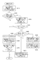
図1は、本発明の実施の形態に係る大型ディスプレイを用いた小画面表示システム(以下、小画面表示システムと略す)100の概観構成を示す図である。小画面表示システム100は、例えば、100インチを超えるような大画面11を有する表示装置1と、大画面11前方の検知範囲Sにおける利用者Hを検出するセンサ装置2と、センサ装置2の利用者検出の態様に応じて、表示装置1の大画面11上に利用者Hごとの小画面7を生成して表示する表示制御装置3と、を備えて構成され、個々の利用者Hの目線に応じて最適な位置に最適な小画面7を表示するようになっている。なお、本実施の形態においては、図1に示すような座標軸、すなわち、矩形の大画面11の横方向をx軸、縦方向をz軸(大画面11はxz平面上にある)、大画面11に垂直な方向をy軸とした座標軸を用いて、以下、説明を行う。
次に、図4~図7を用いて、本発明の実施の形態に係る小画面表示システム100の動作について説明する。ここで、図4は、小画面表示システム100の位置検出部10における範囲検出処理P10の流れを示すフローチャートであり、図5は、小画面表示システム100の位置検出部10における詳細位置検出処理P20の流れを示すフローチャートである。また、図6は、小画面表示システム100の画面処理部30における画面表示処理P30の流れを示すフローチャートであり、図7は、小画面表示システム100の画面処理部30における画面消去処理P40の流れを示すフローチャートである。
範囲検出処理P10は、上述したように、物体が存在する大まかな位置を検出する処理であり、位置検出部10において常時、稼働している。
詳細位置検出処理P20は、上述したように、範囲検出処理P10で検出された物体が人であるか否かを判断し、人である場合には、人の視線位置を算出する処理であり、範囲検出処理P10からの指示により起動する。
画面表示処理P30は、上述したように、位置検出部10で新たに検出された利用者Hの視線位置に小画面7を表示する処理であり、詳細位置検出処理P20からの指示により起動する。
画面消去処理P40は、上述したように、利用者Hが小画面7を見ることを止めたときに当該利用者Hが見ていた小画面7を消去する処理であり、詳細位置検出処理P20からの指示により起動する。
次に、上述した小画面表示システム100の小画面表示制御を利用者Hの行動と対比して具体的に説明する。
図8を参照して、利用者HAが小画面7A、利用者HBが小画面7Bをそれぞれ見ている状態から、利用者HBが利用者HAに近づく場合について説明する。
図9を参照して、利用者HAが小画面7Aを見ているときに、別の利用者HBが近づいて来る場合について説明する。
図10を参照して、利用者HAと利用者HBがほぼ同時に検知範囲Sに進入してきて、小画面7を見る場合について説明する。
図11を参照して、まず、利用者HA及び利用者HBが小画面7Aを見ている状態から、利用者HBが立ち去る場合について説明する。この場合には、利用者HAだけが小画面7Aを見ることになるので、小画面表示システム100は、利用者HAの視線位置に合わせて、小画面7Aを移動して表示する(画面消去処理のステップS530(NO)、S550(NO)、S560参照)。この結果、利用者HAは自分の視線位置に表示された小画面7Aを見ることとなる。
Claims (15)
- 第1の大きさの画像表示面を有する表示手段と、
前記画像表示面の前方の所定領域に存在する利用者の視線位置を検出する位置検出手段と、
前記位置検出手段が検出した前記利用者の視線位置に合わせて、前記画像表示面上に前記第1の大きさよりも小さな第2の大きさの小画面を表示する画面処理手段と、
を有することを特徴とする画面表示システム。 - 前記画面処理手段は、
前記位置検出手段が検出した前記利用者が移動したと判断した場合には、前記利用者の視線に合わせて表示した小画面を消去することを特徴とする請求項1記載の画面表示システム。 - 前記位置検出手段は、
前記画像表示面の前方の所定領域に存在する複数の利用者それぞれの視線位置を検出し、
前記画面処理手段は、
前記位置検出手段が検出した前記複数の利用者それぞれの視線位置に合わせて、前記第2の大きさの小画面をそれぞれ表示することを特徴とする請求項1記載の画面表示システム。 - 前記画面処理手段は、
前記位置検出手段が検出した複数の利用者それぞれの視線位置が予め定めた範囲内にある場合には、前記複数の利用者の視線位置に基づいて、前記第2の大きさの共通小画面を1つ表示することを特徴とする請求項3記載の画面表示システム。 - 前記画面処理手段は、
前記共通小画面を前記複数の利用者それぞれの視線位置を平均した位置に表示することを特徴とする請求項4記載の画面表示システム。 - 前記画面処理手段は、
前記複数の利用者のうち、前記位置検出手段が検出した最初の利用者の視線位置に合わせて、前記共通小画面を表示することを特徴とする請求項4記載の画面表示システム。 - 前記画面処理手段は、
前記位置検出手段が前記複数の利用者のうち、いずれかの利用者の移動を判断した場合には、残された利用者の視線位置に基づいて、前記共通小画面を移動して表示することを特徴とする請求項4乃至6のいずれか1項に記載の画面表示システム。 - 前記画面処理手段は、
前記残された利用者が2人以上の場合には、前記共通小画面を前記残された利用者の視線位置を平均した位置に表示することを特徴とする請求項7記載の画面表示システム。 - 前記画面処理手段は、
前記残された利用者が1人の場合には、前記共通小画面を前記残された利用者の視線位置に合わせて表示することを特徴とする請求項7記載の画面表示システム。 - 前記画面処理手段は、
前記位置検出手段が検出した複数の利用者それぞれの視線位置が予め定めた範囲内にあって、複数の利用者それぞれの視線位置の高さの差異が予め定めた閾値以上の場合には、前記複数の利用者それぞれの視線位置に合わせて、前記第2の大きさの小画面をそれぞれ表示することを特徴とする請求項4記載の画面表示システム。 - 前記位置検出手段は、
複数の人の体型及び姿勢に関する三次元形状パターンを備えており、
検出した形状と、前記三次元形状パターンと比較することで検出した物体が人であるか否かを判定する第1の検出手段と、
検出した物体が人である場合には、検出した利用者の頭頂の3次元位置を検出する第2の検出手段と、
前記検出した利用者の頭頂の3次元位置から予め定められた方法により視線位置を算出する補正手段と、
を備えることを特徴とする請求項1乃至10のいずれか1項に記載の画面表示システム。 - 前記画面処理手段は、
前記位置検出手段が検出した前記利用者の視線位置の前記画像表示面からの距離に基づいて、前記第2の大きさを変化させることを特徴とする請求項1乃至11のいずれか1項に記載の画面表示システム。 - 前記画面処理手段は、
前記位置検出手段が検出した前記利用者の視線位置の移動に追随して、前記第2の大きさの小画面を表示することを特徴とする請求項1記載の画面表示システム。 - 第1の大きさの画像表示面を有する表示手段に情報を表示するコンピュータが読み取り可能な画面表示プログラムであって、
前記画像表示面の前方の所定領域に存在する利用者の視線位置を検出する位置検出ステップと、
前記位置検出ステップで検出した前記利用者の視線位置に合わせて、前記画像表示面上に前記第1の大きさよりも小さな第2の大きさの小画面を表示する画面処理ステップと、
を前記コンピュータに実行させることを特徴とする画面表示プログラム。 - 前記画面処理ステップは、
前記位置検出ステップで検出した前記利用者が移動したと判断した場合には、前記第2の大きさの小画面を消去することを特徴とする請求項13記載の画面表示プログラム。
Priority Applications (3)
| Application Number | Priority Date | Filing Date | Title |
|---|---|---|---|
| PCT/JP2008/057071 WO2009125481A1 (ja) | 2008-04-10 | 2008-04-10 | 画面表示システム及び画面表示プログラム |
| US12/937,437 US20110032274A1 (en) | 2008-04-10 | 2008-04-10 | Screen display system and screen display program |
| JP2010507089A JP5058335B2 (ja) | 2008-04-10 | 2008-04-10 | 画面表示システム及び画面表示プログラム |
Applications Claiming Priority (1)
| Application Number | Priority Date | Filing Date | Title |
|---|---|---|---|
| PCT/JP2008/057071 WO2009125481A1 (ja) | 2008-04-10 | 2008-04-10 | 画面表示システム及び画面表示プログラム |
Publications (1)
| Publication Number | Publication Date |
|---|---|
| WO2009125481A1 true WO2009125481A1 (ja) | 2009-10-15 |
Family
ID=41161624
Family Applications (1)
| Application Number | Title | Priority Date | Filing Date |
|---|---|---|---|
| PCT/JP2008/057071 WO2009125481A1 (ja) | 2008-04-10 | 2008-04-10 | 画面表示システム及び画面表示プログラム |
Country Status (3)
| Country | Link |
|---|---|
| US (1) | US20110032274A1 (ja) |
| JP (1) | JP5058335B2 (ja) |
| WO (1) | WO2009125481A1 (ja) |
Cited By (12)
| Publication number | Priority date | Publication date | Assignee | Title |
|---|---|---|---|---|
| JP2011242699A (ja) * | 2010-05-20 | 2011-12-01 | Canon Inc | 情報提示システム及びその制御方法、プログラム |
| CN102467345A (zh) * | 2010-11-08 | 2012-05-23 | 夏普株式会社 | 显示装置和显示方法 |
| EP2514196A2 (en) * | 2009-12-17 | 2012-10-24 | LG Electronics Inc. | Image display apparatus and method for operating the image display apparatus |
| JP2013152711A (ja) * | 2011-12-28 | 2013-08-08 | Nikon Corp | 投影装置及び表示装置 |
| JP2014153666A (ja) * | 2013-02-13 | 2014-08-25 | Mitsubishi Electric Corp | 広告提示装置 |
| WO2015029554A1 (ja) | 2013-09-02 | 2015-03-05 | ソニー株式会社 | 情報処理装置、情報処理方法、及びプログラム |
| WO2015049931A1 (ja) * | 2013-10-04 | 2015-04-09 | ソニー株式会社 | 情報処理装置、情報処理方法、及びプログラム |
| WO2015190093A1 (ja) * | 2014-06-10 | 2015-12-17 | 株式会社ソシオネクスト | 半導体集積回路およびそれを備えた表示装置並びに制御方法 |
| JP2017068697A (ja) * | 2015-09-30 | 2017-04-06 | ブラザー工業株式会社 | 投影制御装置、及びプログラム |
| JP2020530631A (ja) * | 2017-08-14 | 2020-10-22 | シェンジェン ピーアールテック カンパニー リミテッド | インタラクション位置決定方法、システム、記憶媒体、およびスマートデバイス |
| JP2020533695A (ja) * | 2017-09-08 | 2020-11-19 | 株式会社ソニー・インタラクティブエンタテインメント | 空間的な、ユーザを認識している、コンパニオンロボットまたはデバイスからの第2のスクリーンの投影 |
| US11960647B2 (en) | 2020-04-24 | 2024-04-16 | Sharp Nec Display Solutions, Ltd. | Content display device, content display method, and storage medium using gazing point identification based on line-of-sight direction detection |
Families Citing this family (14)
| Publication number | Priority date | Publication date | Assignee | Title |
|---|---|---|---|---|
| JP2010137009A (ja) * | 2008-12-15 | 2010-06-24 | Nintendo Co Ltd | キャリブレーションプログラム及び座標検出装置 |
| JP5310456B2 (ja) * | 2009-10-05 | 2013-10-09 | ソニー株式会社 | 情報処理装置、情報処理方法および情報処理システム |
| US9875719B2 (en) | 2009-12-23 | 2018-01-23 | Gearbox, Llc | Identifying a characteristic of an individual utilizing facial recognition and providing a display for the individual |
| US20110211738A1 (en) * | 2009-12-23 | 2011-09-01 | Searete Llc, A Limited Liability Corporation Of The State Of Delaware | Identifying a characteristic of an individual utilizing facial recognition and providing a display for the individual |
| US8990682B1 (en) * | 2011-10-05 | 2015-03-24 | Google Inc. | Methods and devices for rendering interactions between virtual and physical objects on a substantially transparent display |
| JP2015056141A (ja) | 2013-09-13 | 2015-03-23 | ソニー株式会社 | 情報処理装置、および情報処理方法 |
| JP2015127897A (ja) * | 2013-12-27 | 2015-07-09 | ソニー株式会社 | 表示制御装置、表示制御システム、表示制御方法、およびプログラム |
| CN106970697B (zh) * | 2016-01-13 | 2020-09-08 | 华为技术有限公司 | 界面交互装置及方法 |
| EP3473388A4 (en) * | 2016-06-16 | 2020-01-29 | Shenzhen Royole Technologies Co., Ltd. | METHOD AND DEVICE FOR MULTIPLE-USER INTERACTION AND CHAPERON ROBOTS |
| JP6726889B2 (ja) * | 2016-06-20 | 2020-07-22 | パナソニックIpマネジメント株式会社 | 映像表示システム |
| US10623815B2 (en) * | 2017-10-02 | 2020-04-14 | International Business Machines Corporation | Masking screen responsive to viewpoint |
| JP2022037377A (ja) * | 2020-08-25 | 2022-03-09 | 株式会社ワコム | 入力システム及び入力方法 |
| GB2607569A (en) * | 2021-05-21 | 2022-12-14 | Everseen Ltd | A user interface system and method |
| TWI823469B (zh) * | 2022-07-11 | 2023-11-21 | 矽統科技股份有限公司 | 電子系統振動回饋方法以及振動回饋電子系統 |
Citations (5)
| Publication number | Priority date | Publication date | Assignee | Title |
|---|---|---|---|---|
| JPH08278758A (ja) * | 1995-04-10 | 1996-10-22 | Fujitsu General Ltd | 画像表示装置 |
| JPH11327753A (ja) * | 1997-11-27 | 1999-11-30 | Matsushita Electric Ind Co Ltd | 制御方法及びプログラム記録媒体 |
| JP2001319217A (ja) * | 2000-05-09 | 2001-11-16 | Fuji Photo Film Co Ltd | 画像表示方法 |
| JP2003330697A (ja) * | 2002-05-14 | 2003-11-21 | Takenaka Komuten Co Ltd | 情報表示装置 |
| JP2007272365A (ja) * | 2006-03-30 | 2007-10-18 | Advanced Telecommunication Research Institute International | コンテンツ提示装置 |
Family Cites Families (5)
| Publication number | Priority date | Publication date | Assignee | Title |
|---|---|---|---|---|
| EP0919906B1 (en) * | 1997-11-27 | 2005-05-25 | Matsushita Electric Industrial Co., Ltd. | Control method |
| US20020046100A1 (en) * | 2000-04-18 | 2002-04-18 | Naoto Kinjo | Image display method |
| US20040093620A1 (en) * | 2002-02-04 | 2004-05-13 | Daisuke Iino | Advertisement program providing system |
| US20030161505A1 (en) * | 2002-02-12 | 2003-08-28 | Lawrence Schrank | System and method for biometric data capture and comparison |
| US8115877B2 (en) * | 2008-01-04 | 2012-02-14 | International Business Machines Corporation | System and method of adjusting viewing angle for display based on viewer positions and lighting conditions |
-
2008
- 2008-04-10 JP JP2010507089A patent/JP5058335B2/ja not_active Expired - Fee Related
- 2008-04-10 US US12/937,437 patent/US20110032274A1/en not_active Abandoned
- 2008-04-10 WO PCT/JP2008/057071 patent/WO2009125481A1/ja active Application Filing
Patent Citations (5)
| Publication number | Priority date | Publication date | Assignee | Title |
|---|---|---|---|---|
| JPH08278758A (ja) * | 1995-04-10 | 1996-10-22 | Fujitsu General Ltd | 画像表示装置 |
| JPH11327753A (ja) * | 1997-11-27 | 1999-11-30 | Matsushita Electric Ind Co Ltd | 制御方法及びプログラム記録媒体 |
| JP2001319217A (ja) * | 2000-05-09 | 2001-11-16 | Fuji Photo Film Co Ltd | 画像表示方法 |
| JP2003330697A (ja) * | 2002-05-14 | 2003-11-21 | Takenaka Komuten Co Ltd | 情報表示装置 |
| JP2007272365A (ja) * | 2006-03-30 | 2007-10-18 | Advanced Telecommunication Research Institute International | コンテンツ提示装置 |
Cited By (18)
| Publication number | Priority date | Publication date | Assignee | Title |
|---|---|---|---|---|
| EP2514196A2 (en) * | 2009-12-17 | 2012-10-24 | LG Electronics Inc. | Image display apparatus and method for operating the image display apparatus |
| EP2514196A4 (en) * | 2009-12-17 | 2014-02-19 | Lg Electronics Inc | IMAGE DISPLAY DEVICE AND OPERATING METHOD FOR THE IMAGE DISPLAY DEVICE |
| JP2011242699A (ja) * | 2010-05-20 | 2011-12-01 | Canon Inc | 情報提示システム及びその制御方法、プログラム |
| CN102467345A (zh) * | 2010-11-08 | 2012-05-23 | 夏普株式会社 | 显示装置和显示方法 |
| JP2013152711A (ja) * | 2011-12-28 | 2013-08-08 | Nikon Corp | 投影装置及び表示装置 |
| JP2014153666A (ja) * | 2013-02-13 | 2014-08-25 | Mitsubishi Electric Corp | 広告提示装置 |
| US10379610B2 (en) | 2013-09-02 | 2019-08-13 | Sony Corporation | Information processing device and information processing method |
| WO2015029554A1 (ja) | 2013-09-02 | 2015-03-05 | ソニー株式会社 | 情報処理装置、情報処理方法、及びプログラム |
| WO2015049931A1 (ja) * | 2013-10-04 | 2015-04-09 | ソニー株式会社 | 情報処理装置、情報処理方法、及びプログラム |
| JPWO2015049931A1 (ja) * | 2013-10-04 | 2017-03-09 | ソニー株式会社 | 情報処理装置、情報処理方法、及びプログラム |
| US10545623B2 (en) | 2013-10-04 | 2020-01-28 | Sony Corporation | Information processing device and information processing method to coordinate with a plurality of information processing devices |
| WO2015190093A1 (ja) * | 2014-06-10 | 2015-12-17 | 株式会社ソシオネクスト | 半導体集積回路およびそれを備えた表示装置並びに制御方法 |
| JPWO2015190093A1 (ja) * | 2014-06-10 | 2017-06-01 | 株式会社ソシオネクスト | 半導体集積回路およびそれを備えた表示装置並びに制御方法 |
| US10855946B2 (en) | 2014-06-10 | 2020-12-01 | Socionext Inc. | Semiconductor integrated circuit, display device provided with same, and control method |
| JP2017068697A (ja) * | 2015-09-30 | 2017-04-06 | ブラザー工業株式会社 | 投影制御装置、及びプログラム |
| JP2020530631A (ja) * | 2017-08-14 | 2020-10-22 | シェンジェン ピーアールテック カンパニー リミテッド | インタラクション位置決定方法、システム、記憶媒体、およびスマートデバイス |
| JP2020533695A (ja) * | 2017-09-08 | 2020-11-19 | 株式会社ソニー・インタラクティブエンタテインメント | 空間的な、ユーザを認識している、コンパニオンロボットまたはデバイスからの第2のスクリーンの投影 |
| US11960647B2 (en) | 2020-04-24 | 2024-04-16 | Sharp Nec Display Solutions, Ltd. | Content display device, content display method, and storage medium using gazing point identification based on line-of-sight direction detection |
Also Published As
| Publication number | Publication date |
|---|---|
| JPWO2009125481A1 (ja) | 2011-07-28 |
| JP5058335B2 (ja) | 2012-10-24 |
| US20110032274A1 (en) | 2011-02-10 |
Similar Documents
| Publication | Publication Date | Title |
|---|---|---|
| JP5058335B2 (ja) | 画面表示システム及び画面表示プログラム | |
| KR102553190B1 (ko) | 외부 조건들에 기초한 웨어러블 디스플레이 디바이스의 자동 제어 | |
| CN106170083B (zh) | 用于头戴式显示器设备的图像处理 | |
| CN107015638B (zh) | 用于向头戴式显示器用户报警的方法和装置 | |
| JPWO2018016464A1 (ja) | 画像表示システム、並びにヘッドマウントディスプレイの制御装置とその作動方法および作動プログラム | |
| US20120169583A1 (en) | Scene profiles for non-tactile user interfaces | |
| JP7423683B2 (ja) | 画像表示システム | |
| JP6630607B2 (ja) | シミュレーション制御装置及びシミュレーション制御プログラム | |
| KR101993836B1 (ko) | 게임 제어장치 및 이를 포함하는 가상현실 게임 시스템 | |
| KR20230048554A (ko) | 3차원 환경들과의 상호작용을 위한 디바이스들, 방법들 및 그래픽 사용자 인터페이스들 | |
| US11695908B2 (en) | Information processing apparatus and information processing method | |
| JP6340464B1 (ja) | プログラム、情報処理方法、情報処理システム、頭部装着型表示装置、情報処理装置 | |
| CN103513768A (zh) | 一种基于移动终端姿态变化的控制方法及装置、移动终端 | |
| JP6915829B2 (ja) | 親近アンビエントエージェントシステムおよびプログラム | |
| JP6947661B2 (ja) | ヘッドマウントデバイスと通信可能なコンピュータによって実行されるプログラム、当該プログラムを実行するための情報処理装置、およびヘッドマウントデバイスと通信可能なコンピュータによって実行される方法 | |
| JP2010273276A (ja) | テレビ制御装置 | |
| JP6710845B1 (ja) | リハビリテーション支援装置、その方法およびプログラム | |
| JP6625467B2 (ja) | シミュレーション制御装置及びシミュレーション制御プログラム | |
| TWI470565B (zh) | 非接觸式醫療導覽系統及其控制方法 | |
| JP2023123787A (ja) | 情報出力装置、設計支援システム、情報出力方法及び情報出力プログラム | |
| CN111279410B (zh) | 显示设备和显示设备控制方法 | |
| TWI628466B (zh) | 佩戴顯示裝置 | |
| EP4170594A1 (en) | System and method of simultaneous localisation and mapping | |
| CN112365605A (zh) | 场地进入对象的提示方法和系统及其vr眼镜 | |
| TWI463474B (zh) | 影像調整系統及方法 |
Legal Events
| Date | Code | Title | Description |
|---|---|---|---|
| 121 | Ep: the epo has been informed by wipo that ep was designated in this application |
Ref document number: 08740172 Country of ref document: EP Kind code of ref document: A1 |
|
| DPE2 | Request for preliminary examination filed before expiration of 19th month from priority date (pct application filed from 20040101) | ||
| WWE | Wipo information: entry into national phase |
Ref document number: 2010507089 Country of ref document: JP |
|
| NENP | Non-entry into the national phase |
Ref country code: DE |
|
| WWE | Wipo information: entry into national phase |
Ref document number: 12937437 Country of ref document: US |
|
| 122 | Ep: pct application non-entry in european phase |
Ref document number: 08740172 Country of ref document: EP Kind code of ref document: A1 |