WO2009123239A1 - 薬液供給装置 - Google Patents
薬液供給装置 Download PDFInfo
- Publication number
- WO2009123239A1 WO2009123239A1 PCT/JP2009/056753 JP2009056753W WO2009123239A1 WO 2009123239 A1 WO2009123239 A1 WO 2009123239A1 JP 2009056753 W JP2009056753 W JP 2009056753W WO 2009123239 A1 WO2009123239 A1 WO 2009123239A1
- Authority
- WO
- WIPO (PCT)
- Prior art keywords
- chemical solution
- chemical
- chemical liquid
- guide plate
- container
- Prior art date
- Legal status (The legal status is an assumption and is not a legal conclusion. Google has not performed a legal analysis and makes no representation as to the accuracy of the status listed.)
- Ceased
Links
Images







Classifications
-
- E—FIXED CONSTRUCTIONS
- E03—WATER SUPPLY; SEWERAGE
- E03D—WATER-CLOSETS OR URINALS WITH FLUSHING DEVICES; FLUSHING VALVES THEREFOR
- E03D9/00—Sanitary or other accessories for lavatories ; Devices for cleaning or disinfecting the toilet room or the toilet bowl; Devices for eliminating smells
- E03D9/02—Devices adding a disinfecting, deodorising, or cleaning agent to the water while flushing
- E03D9/03—Devices adding a disinfecting, deodorising, or cleaning agent to the water while flushing consisting of a separate container with an outlet through which the agent is introduced into the flushing water, e.g. by suction ; Devices for agents in direct contact with flushing water
- E03D9/032—Devices connected to or dispensing into the bowl
Definitions
- This invention relates to the chemical
- a chemical solution supply device for cleaning the inside of a toilet or obtaining an aroma effect.
- the chemical liquid supply devices described in Patent Documents 1 and 2 are used by hanging a flexible hook provided on a support of a chemical liquid bottle on a rim of the toilet bowl, and hanging the flexible hook on the toilet rim. Is equipped with a chemical receiving part below the chemical bottle. And a chemical
- the chemical solution is discharged from the chemical solution container and supplied into the toilet as follows.
- a plate with a porous pad or a groove (slot) is disposed as a chemical solution receiving portion below a chemical solution container supported by a housing, and a conduit that extends from the lower end of the chemical solution container and contacts the chemical solution receiving portion is provided.
- the chemical liquid is supplied to the chemical liquid receiver.
- the pad or plate of the chemical solution receiving part is disposed horizontally, and when the cleaning water in the toilet flows, the chemical solution collected therein moves into the toilet along with the cleaning water flowing in contact with the chemical solution receiving part.
- a grooved plate constituting the chemical solution receiving portion is arranged in a similar structure so as to descend to 5 to 20 degrees toward the inside of the toilet.
- the chemical solution supplied from the chemical solution container is easy to move to the groove due to the inclination of the plate, but after the movement, the chemical solution is collected on the plate, and the toilet wash water enters the chemical solution receiving part. By flowing in contact, the drug solution moves into the toilet along with the wash water.
- the chemical solution is stored in the chemical solution receiving portion, and when the cleaning water flows, it moves into the toilet along with the cleaning water.
- the present invention has been made in order to solve the above-mentioned problem, and can be attached to a toilet rim so that a chemical solution can be mixed into cleaning water in the toilet bowl, and can function even if attached to a position that does not contact cleaning water. It aims at providing the chemical
- the object of the present invention is a chemical solution supply device attached to a toilet rim, the device main body supporting the chemical solution container, and provided in the device main body, connected to the discharge port of the chemical solution container, A chemical solution discharge mechanism that guides and discharges from the discharge port and a hanging member for hanging the apparatus main body on the rim of the toilet bowl, and the chemical solution discharge mechanism guides the chemical solution from the communication portion to the discharge port of the chemical solution container.
- a chemical solution passage extending in the vertical direction so as to be discharged from the lower outflow hole, and a hanging piece extending downward from a position in contact with or close to the opening edge of the outflow hole, the hanging piece having a capillary action This is achieved by a chemical supply device characterized in that a lead-out groove is formed for continuously leading out the chemical from the outflow hole and discharging it downward from the hanging piece.
- the device main body that is hung on the toilet rim by the hanging member includes a chemical solution discharge mechanism that guides and discharges the chemical solution from the discharge port of the chemical solution container, and the chemical solution discharge mechanism is configured to discharge the chemical solution container. Since it has a chemical liquid passage that extends in the vertical direction so that the chemical liquid is guided from the communicating part to the outlet and discharged from the lower outflow hole, the chemical liquid in the chemical container supported by the device body is discharged from the outflow hole through the chemical liquid passage. can do.
- the apparatus body includes a hanging piece extending downward from a position in contact with or close to the opening edge of the outflow hole, and the dripping piece continuously draws the chemical solution from the outflow hole by capillary action.
- the lead-out groove extends downward from the upper end of the drooping piece by more than 10 mm, and more preferably 12 mm or more.
- the lead-out groove has a function of discharging the chemical liquid while guiding it downward by extending downward beyond a predetermined length. Therefore, if the length of the lead-out groove is below the lower limit value, a sufficient discharge amount of the chemical solution cannot be obtained.
- the length of the outlet groove exceeds 20 mm, the device becomes too long downward, making it difficult to install on the toilet, the container becoming too large to be noticeable, or the container becoming dirty with dirt. In some cases, the installation position of the apparatus is likely to change due to the flow of cleaning water. From such a viewpoint, it is preferably 20 mm or less.
- the chemical solution supply apparatus receives the chemical solution discharged from the outlet groove, and causes the chemical solution to flow out together with the cleaning water when it comes into contact with the cleaning water flowing through the toilet.
- a guide plate can be further provided.
- channel is stored to some extent on a guide plate, and if it exceeds storage amount, it will dripped from a guide plate. Therefore, when the wash water of the toilet comes into contact with the guide plate, the stored chemical liquid flows out at a time, and a high medicinal effect can be exhibited immediately after use of the toilet.
- the chemical supply device In the case of a chemical supply device attached to a toilet rim, since the chemical supply device must not hinder the flow of cleaning water in the toilet bowl, the chemical supply device has a limited contact area with the cleaning water. Therefore, the chemical solution stored on the guide plate can be discharged by providing the guide plate and guiding the cleaning water onto the guide plate within a range that does not disturb the water flow. Further, by providing the guide plate in this way, it is not necessary to bring the drooping piece into direct contact with the washing water, so that the problem that the washing water flows back through the drooping piece and into the chemical solution container is also avoided. Is done.
- the guide plate may extend from a position below the hanging piece toward the hanging member.
- the guide plate is inclined so as to descend from the position below the hanging piece toward the hanging member. Can do. Depending on properties such as the viscosity and wettability of the chemical solution, the chemical solution may stay on the guide plate at a position below the drooping piece. By tilting the guide plate in this way, retention is prevented. Can do.
- the chemical solution supply apparatus of the above (3) to (5) may be formed with an extension groove for guiding the chemical solution into the groove by capillary action on the upper surface of the guide plate.
- a through hole is formed in the guide plate for allowing the chemical liquid supplied from the hanging piece to the guide plate to pass through and drop. Can be. If the liquid medicine can be dripped from the through hole in this way, the mounting state of the liquid medicine supply device on the toilet becomes inadequate, and the flushing water of the toilet does not reach the guide plate or is insufficiently reached. Even if it becomes, a chemical
- a chemical solution supply apparatus that can be attached to the rim of a toilet bowl and can mix the chemical solution into the wash water in the toilet bowl and that can function even if attached to a position that does not contact the wash water. Can be provided.
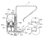
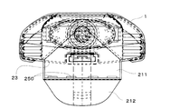
- FIG. 3 is a cross-sectional view of FIG. 1 taken along line AA of FIG. It is a bottom view of FIG.
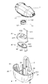
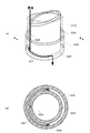
- FIG. 2 is an exploded perspective view of FIG. 1. It is a perspective view of a lower member, a top view, a front view, and a bottom view.
- FIG. 4 is a partial perspective view of the lower member and a sectional view taken along line BB. It is a longitudinal front view which expands and shows centering on the supply part and chemical
- FIG. 1 is a perspective view of a chemical liquid supply apparatus according to the present embodiment
- FIG. 2 is a cross-sectional view of FIG. 1
- FIG. 3 is a cross-sectional view of FIG. 1 along the AA line of FIG.
- FIG. 5 is an exploded perspective view of FIG.
- This chemical solution supply device is used by being hung on a toilet rim.
- a chemical solution container 1 containing a chemical solution and an apparatus main body 2 for supporting the chemical solution container 1 from below.
- a suspension member 3 for hanging the device on the rim.
- a chemical liquid discharge mechanism 4 that supplies the chemical liquid flowing out from the chemical liquid container 1 to the bottom surface of the apparatus main body 2 is disposed inside the apparatus main body 2.
- the chemical liquid container 1 is formed in a transparent dome shape and has a discharge port 11 on the lower surface.
- a cap 13 is attached to the discharge port 11.
- the cap 13 is composed of an annular main body 131 and a thin film portion 132 that closes the central hole. When used, the cap 13 breaks the thin film portion 132 to discharge the chemical solution.
- the viscosity of the chemical solution stored in the chemical solution container 1 is not particularly limited. For example, it is 80 to 500 mPa ⁇ s at 25 ° C., or 200 to 2000 mPa ⁇ s at 5 ° C., preferably 120 to 300 mPa ⁇ s at 25 ° C. S, or 300 to 1200 mPa ⁇ s at 5 ° C.
- the viscosity here is set at a set temperature of 5 ° C. or 25 ° C. in a B type viscometer (manufactured by Toki Sangyo Co., Ltd .: model number TVB-10 type viscometer). 2. Measured under conditions of stirring conditions of 30 rpm and stirring time of 1 minute.
- the apparatus main body 2 has a guide plate 21 constituting the bottom surface and a wall body 22 surrounding the periphery thereof.
- the guide plate 21 includes a base portion 211 having a substantially rectangular shape in plan view and a movable portion 212 that is swingably connected to one side thereof.
- the guide plate 21 has three sides other than the side where the movable portion 212 is provided.
- the above-described wall body 22 is provided in a U shape in plan view. Therefore, the apparatus main body 2 is formed in a cup shape in which a wall on one side is cut out and is configured such that a part of the base portion 211 and the movable portion 212 protrude from the open portion 23. Then, as will be described later, running water flows into the apparatus main body 2 from the open portion 23.
- a support column 24 extending upward is attached to the center of the base portion 211, and the suspension member 3 is attached to a space between the support column 24 and a cover member 411 described later so as to be movable up and down.
- the hanging member 3 is formed in a band shape that is bent at two locations so as to be elastically deformable. In an initial state, the hanging member 3 is folded as shown in FIG. Further, since the hanging member 3 is configured to be movable up and down, the height of the chemical solution container 1 and the apparatus main body 2 with respect to the rim can be adjusted so that the apparatus and the rim do not interfere with each other.
- the base portion 211 and the movable portion 212 are integrally formed of resin or the like, and the base portion 211 is about 6 degrees toward the movable portion 212 side. Inclined downward. As a result, as will be described later, the discharged chemical liquid can easily flow to the rim side.
- the inclination angle ⁇ of the base 211 can be set to other values, for example, can be 0 to 45 degrees, and is preferably 3 to 30 degrees.
- a groove 213 is formed on the back surface of the guide plate 21 along the boundary line between the base portion 211 and the movable portion 212. Therefore, since the boundary between the base 211 and the movable portion 212 is formed into a thin film shape by the groove 213, the movable portion 212 can swing with respect to the base 211. Further, since the groove 213 is formed on the back surface of the guide plate 21, when the movable portion 212 is inclined downward, the opposing side wall surfaces in the groove 213 come into contact with each other, and thereby the downward inclination is restricted. (FIG. 2A). On the other hand, it is possible to tilt upward, and if a force is applied, the movable portion 212 can be swung upward.
- a substantially rectangular side plate 214 is attached to both side portions of the base portion 211, and an end surface extending vertically toward the movable portion 212 side of the side plate 214 is a movable portion 212.
- the movable portion 212 is inclined upward at an inclination angle ⁇ of about 30 ° with respect to the base portion 211.
- the movable portion 212 is about 0 to 90 ° with respect to the base portion 211 by elastic deformation of the boundary portion. Inclination is possible within a certain range.
- a plurality of water holes 25 are formed in the peripheral edge of the base portion 211 and the wall body 22, and the water flowing in from the open portion 23 passes through these water holes 25 to form the apparatus. It is discharged from the main body 2 (see FIG. 5).
- the chemical solution discharge mechanism 4 is disposed between the chemical solution container 1 and the guide plate 21, and includes an upper member 41 disposed on the upper side and a lower member disposed on the lower side. 42.
- the upper member 41 is formed in an elliptical cylindrical shape in plan view, and the lower part is open.
- the lower member 42 includes a plate-like portion 421 having an elliptical shape in plan view, and a low wall member 423 formed so as to extend in the vertical direction around the lower portion 42 so as to block the lower opening of the upper member 41. Placed in.
- medical solution is formed between both by combining the upper member 41 and the lower member 42.
- the upper member 41 and the lower member 42 will be described in more detail.
- a rail-like cover member 411 extending upward is attached to the side surface of the upper member 41. As described above, the cover member 411 abuts on the support column 24 and is suspended. A space for accommodating the hanging member 3 is formed.
- the upper member 41 is provided with a sharp cylindrical communication pipe 412 with a sharply cut end at the center of the upper surface, and a total of four air circulation holes 413 at the end of the upper surface. .
- the communication tube 412 is pierced into the cap 13 of the chemical solution container 1 when the apparatus is used, and serves as a communication portion that breaks the thin film portion 132 and takes out the chemical solution from the discharge port of the chemical solution container.
- annular groove 417 is formed on the periphery of the communication pipe 412, and the main body 131 of the cap 13 is fitted into the groove 417.
- a cylindrical fixed pipe 414 extending toward the lower member 42 and a plurality of chemical liquid communication holes 415 disposed in the vicinity thereof are formed on the inner bottom surface of the communication pipe 412. .
- the chemical solution communication holes 415 and the air circulation holes 413 described above communicate with the buffer space 43.
- FIG. 4B is a sectional view taken along line BB.
- a cylindrical guide tube 424 fitted to the fixed tube 414 of the upper member 41 and a circular fixed wall 425 provided so as to surround the periphery thereof. And are provided.
- the above-described fixed tube 414 is fitted into the gap between the guide tube 424 and the fixed wall 425.
- the upper opening of the guide tube 424 has an obliquely cut shape, and a guide groove 426 extending in the vertical direction along the outer peripheral surface of the guide tube 424 is formed from the lower side of the opening.
- a chemical solution passage (guide channel) is formed by the inner wall surface of the fixed tube 414 and the guide groove 426. Is done.
- a space through which the chemical solution passes is also formed in the gap between the bottom surface of the gap between the guide tube 424 and the fixed wall 425 and the lower end portion of the fixed tube 414.
- the communication pipe 412, the fixed pipe 414, the guide groove 426 of the guide pipe 424, and the extension path 427 form a chemical solution passage that extends from the communication portion to the discharge port of the chemical solution container to the outflow hole 428.
- a pair of leg portions 429 are attached to both ends of the lower surface of the wall member 423 in the lower member 42, and the leg portions 429 provide a space between the lower surface of the lower member 42 and the guide plate 21.
- a space is formed. As will be described later, this space serves as a path for chemicals and running water.
- FIG. 8 is an enlarged cross-sectional view centering on the outflow hole 428 and the drooping piece 430, and shows the upper member 41 (a) and the lower member 42 (b) in a separated state.
- FIG. 9 is an enlarged view showing a transverse section of the hanging piece 430.
- the lead-out groove 435 is formed to have a triangular cross-sectional shape.
- the cross-sectional shape of the groove can be various concave shapes such as a square shape and a semi-circular shape, as well as a part of another polygonal shape or an oval shape.
- sectional dimension and length of the outlet groove 435 are determined so that the chemical liquid can be led out from the opening of the outflow hole 428 by the capillary action and dropped from the lower end in relation to the viscosity and wettability of the chemical liquid to be used.
- FIG. 10 is a side view showing an attached state of the chemical solution supply apparatus.
- the chemical solution container 1 is disposed on the upper member 41.
- the communication pipe 412 is pierced into the cap 13 of the chemical solution container 1 and the chemical solution container 1 is fixed.
- the suspension member 3 is pushed out from the state of FIG. And it arrange
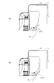
- the movable portion 212 abuts on the inner wall surface of the toilet bowl, but can be swung with respect to the base portion 211, and therefore tilts according to the distance between the base portion 211 and the toilet inner wall surface S. That is, as shown in FIG. 10A, when the distance between the base 211 and the toilet inner wall surface S is small, the movable portion 212 is largely inclined while being pressed against the toilet inner wall surface S, and the gap between the toilet inner wall surface S and Fill. On the other hand, when the distance is large, the inclination angle ⁇ is small as shown in FIG. 10B, but in any case, the gap between the base portion 211 and the toilet inner wall surface S is filled. As a result, since the chemical liquid that has flowed out to the base portion 211 can be efficiently swept away and flowed to the toilet bowl, an excellent cleaning effect can be obtained regardless of the shape of the toilet bowl.
- the flow of the chemical will be described.
- the chemical solution flows out from the chemical solution container 1 to the chemical solution discharge mechanism 4, and a part thereof is in the buffer space 43 via the communication tube 412 and the chemical solution communication hole 415. Flow into.
- the remaining chemical solution flows downward through the guide groove 426 and then reaches the lower end openings of the extension path 427 and the outflow hole 428.
- the reached chemical solution is led out from the outflow hole 428 by the capillary action of the lead-out groove 435 of the hanging piece 430 in contact with the lower end opening edge of the outflow hole 428, and moves downward through the lead-out groove 435.
- the chemical solution thus moved further moves onto the guide plate 21 at the contact portion between the guide plate 21 and the hanging piece 430 and drops from the guide plate when the amount stored in the guide plate 21 is exceeded.
- a through hole 250 that penetrates the guide plate in the vertical direction is formed at a position near the movable portion 212 in the base portion 211 of the guide plate 21.
- the through hole 250 has an effect of allowing the chemical solution supplied from the hanging piece 430 to the guide plate 21 to pass therethrough and discharging it downward. If the liquid medicine can be dropped from the through-hole 250 in this way, the state in which the liquid medicine supply device is attached to the toilet becomes inadequate, and the flushing water of the toilet does not reach the guide plate or is insufficiently reached. Even if it becomes, a chemical
- an extension groove 216 (indicated by a one-dot chain line in FIG. 1) for guiding the chemical solution into the groove by capillary action can be formed on the upper surface of the guide plate 21. By doing so, the transfer of the chemical solution from the hanging piece 430 to the guide plate 21 becomes smoother. In addition, more chemical liquid can be retained on the guide plate 21, and more chemical liquid can be supplied to the toilet at the time of flushing.
- the chemical moves from the outlet groove 435 to the guide plate 21 through the contact portion, and the discharge from the outlet groove is smooth.
- the chemical solution may stay at the contact portion between the hanging piece and the guide plate, thereby preventing discharge from the outlet groove.
- the guide plate is tilted so as to descend from the contact point with the hanging piece toward the hanging member 3 (toilet rim side), or a chemical solution is applied to the upper surface of the guide plate by capillary action.
- the hanging piece may have a lower end that extends to a position apart from the upper surface of the guide plate.
- the chemical solution is dropped from the drooping piece onto the guide plate, or when the gap between the two is small, the chemical solution is transferred to fill the gap.
- the residence in the contact location of a drooping piece and a guide plate is prevented.
- one or both of the inclination and the expansion groove can be employed for the guide plate.
- the buffer space 43 functions as a buffer when a pressure change occurs in the chemical liquid container 1 due to a temperature change. For example, when the temperature rises and the chemical solution container 1 is warmed, the air in the container 1 expands and the inside of the container 1 becomes positive pressure. In this case, the chemical solution in the chemical solution container 1 is pushed out and discharged. However, since this chemical solution flows into the buffer space 43 through the chemical solution communication hole 415 in addition to the guide groove 426, the chemical solution is excessive from the guide groove 426. Is prevented from being leaked into the water.
- the pressure of the air acts on the chemical liquid through the air circulation holes 413.
- the buffer space 43 is sucked into the chemical liquid container 1 through the chemical liquid communication hole 415.
- the buffer space 43 is in the container 1 because most of the chemical liquid flows between the chemical liquid container 1 and the buffer space 43 even when a pressure change occurs in the chemical liquid container 1 due to a temperature change. It is possible to prevent the chemical solution from flowing out excessively or restricting outflow.
- the flushed water travels along the toilet bowl inner wall surface S from the inside of the rim R as shown in FIG. Guided to the base 211 side (arrow X). Then, while the chemical solution on the guide plate 21 is exposed, it flows out from the water flow hole 25 and the through-hole 250 or bounces off against the wall body 22 in the apparatus and flows out from the open part 23 to the outside of the apparatus. Thus, the chemical solution is supplied to the toilet inner wall surface S together with running water, and the toilet bowl is cleaned.
- the washing water flowing onto the guide plate 21 may flow back into the chemical solution discharge mechanism 4 and enter the chemical solution container 1, but this is dealt with as follows. That is, in the apparatus according to the present embodiment, the chemical solution is discharged onto the guide plate 21 through the guide groove 426, the extension path 427, and the outflow hole 428, through the outlet groove 435 of the drooping piece 430. Accordingly, the cleaning water from the guide plate toward the chemical solution container must move with the drooping piece 430 upward. In this case, the drooping piece and the lead-out groove are elongated downward so that the lead-out groove 435 easily guides the chemical solution from the lower end opening of the outflow hole 428, so that the washing water rises and reaches the outflow hole 428.
- the extension path 427 extends horizontally, the water that has flowed upward through the lead-out groove 435 of the hanging piece 430 passes through the extension path 427 that extends once horizontally, and then passes through the guide groove 426 that extends further vertically. If it does not pass, the chemical solution container 1 is not reached.
- medical solution container 1 is formed, the penetration
- the chemical solution in the chemical solution container reaches the outflow hole 428 through the above-described chemical solution passage, is led out to the lead-out groove 435 of the hanging piece 430, and is spread and stored on the guide plate 21.
- the amount of storage is exceeded, it drops from the guide plate 21 into the toilet bowl. In this way, since the chemical solution is continuously supplied into the toilet bowl, even if the device does not reach the position where it comes into contact with the wash water or may come off from such a position after installation, supply of the chemical solution Is secured and the medicinal effect is sustained.
- This chemical solution had a viscosity of 240 mPa ⁇ s at 25 ° C. and 690 mPa ⁇ s at 5 ° C.
- the viscosity was measured using a B-type viscometer (manufactured by Toki Sangyo Co., Ltd .: Model number TVB-10 viscometer) at a set temperature of 25 ° C. or 5 ° C. 2. Measurement was performed under the conditions of stirring at 30 rpm and stirring time of 1 minute.
- the hanging piece itself has a structure that makes it difficult to directly contact the washing water. Therefore, as in these comparative examples, when the drug solution does not transfer from the drooping piece to the guide plate, the flushing is not promoted and the function does not function in use.
- the container of the example is a container suitable for use because the chemical liquid is steadily reduced even when left as described above and the liquid is steadily reduced even when flushed.
Landscapes
- Health & Medical Sciences (AREA)
- Public Health (AREA)
- Epidemiology (AREA)
- Life Sciences & Earth Sciences (AREA)
- Engineering & Computer Science (AREA)
- Hydrology & Water Resources (AREA)
- Water Supply & Treatment (AREA)
- Bidet-Like Cleaning Device And Other Flush Toilet Accessories (AREA)
Abstract
【課題】便器のリムに取り付けられて便器内の洗浄水に薬液を混入させ得ると共に、洗浄水に接しない位置に取り付けられても機能を発揮し得る薬液供給装置を提供する。 【解決手段】便器のリムに取り付けられる薬液供給装置であって、薬液容器1を支持する装置本体2と、該装置本体に設けられ、薬液容器1の排出口11に接続され薬液を該排出口から導いて排出する薬液排出機構4と、吊掛部材3とを備え、薬液排出機構4は、薬液容器1の排出口11への連通部から薬液を導き下方の流出孔428から排出する薬液通路と、流出孔428の開口縁に当接又は近接する位置から下方へ延びた垂下片430とを備え、該垂下片には、毛管作用により流出孔428から薬液を継続的に導出して該垂下片から滴下させる導出溝435が形成されている薬液供給装置。
Description
本発明は、水洗式便器のリムに取り付けられ、芳香、消臭、洗浄等のための薬液を便器内に供給する薬液供給装置に関する。
便器内を洗浄したり、芳香効果を得るための薬液供給装置として、便器のリムに取り付けて使用するタイプのものが種々提案されている。例えば、特許文献1及び2に記載の薬液供給装置は、薬液ボトルの支持体に設けられた可撓性フックを便器のリムに係止することにより、便器内に吊り掛けて使用され、支持体には薬液ボトルの下方に薬液受け部を取り付けている。そして、薬液ボトルから薬液受け部上に供給される薬液を水洗時の流水によってさらうことで、便器内に薬液を供給している。これによって、便器が洗浄されるとともに、薬液に芳香剤を含ませれば芳香効果も得ることができる。
より具体的には、薬液は以下のようにして薬液容器から排出され便器内へと供給される。特許文献1の装置では、ハウジングに支持した薬液容器の下方に多孔性パッド又は溝(スロット)付きのプレートを薬液受け部として配置し、薬液容器下端の口部から延び薬液受け部に接する導管を経て薬液が薬液受け部に供給される。薬液受け部のパッド又はプレートは水平に配置され、そこに溜まった薬液は、トイレの洗浄水が流れると、薬液受け部に接して流れる該洗浄水に伴われて便器内へと移動する。
特許文献2の装置では、同様の構造により薬液受け部を構成する溝付きのプレートが便器の内側に向けて5~20度に下降するように配置される。この装置では、薬液容器から供給された薬液がプレートの傾斜により溝へと移動しやすくなってはいるが、移動後は薬液がプレート上に溜まった状態となり、トイレの洗浄水が薬液受け部に接して流れることにより、薬液は洗浄水に伴われて便器内へと移動する。
このように、従来のリム吊り下げタイプの薬液供給装置は、薬液受け部に薬液を溜め、洗浄水が流れたときに、洗浄水に伴われて便器内へ移動するようになっていた。
ところが、このようなリム吊り下げタイプの薬液供給装置は、ユーザによって家庭内などで取り付けられるため、必ずしも便器の適正な位置に取り付けられるとは限らない。薬液供給装置が機能するためには、薬液受け部が便器の洗浄水に確実に接するようにして位置を決めた上で、フックをリムに係止して固定する必要がある。しかしながら、取り付けの際に、薬液受け部が洗浄水に接する適正位置に至っていなかったり、取り付け時には適正位置となっていても固定が不十分なために使用期間中に適正位置から外れたりすることがある。このような場合には、薬液受け部に洗浄水が到達しないので、薬液は薬液受け部に溜まったまま放置され、便器内に移動しない。その結果、薬液供給装置の機能が発揮されないという問題を生じる。
本発明は、上記問題を解決するためになされたものであり、便器のリムに取り付けられて便器内の洗浄水に薬液を混入させ得ると共に、洗浄水に接しない位置に取り付けられても機能を発揮し得る薬液供給装置を提供することを目的とする。
(1)本発明の前記目的は、便器のリムに取り付けられる薬液供給装置であって、薬液容器を支持する装置本体と、該装置本体に設けられ、薬液容器の排出口に接続され薬液を該排出口から導いて排出する薬液排出機構と、前記装置本体を便器のリムに吊り掛けるための吊掛部材とを備え、前記薬液排出機構は、薬液容器の排出口への連通部から薬液を導き下方の流出孔から排出するように上下方向に延びた薬液通路と、前記流出孔の開口縁に当接又は近接する位置から下方へ延びた垂下片とを備え、該垂下片には、毛管作用により前記流出孔から薬液を継続的に導出して該垂下片から下方へ排出させる導出溝が形成されていることを特徴とする薬液供給装置により達成される。
この薬液供給装置においては、吊掛部材により便器のリムに吊り掛けられる装置本体が、薬液容器の排出口から薬液を導いて排出する薬液排出機構を備え、該薬液排出機構は、薬液容器の排出口への連通部から薬液を導き下方の流出孔から排出するように上下方向に延びた薬液通路を備えているので、装置本体に支持した薬液容器内の薬液を薬液通路を経て流出孔から排出することができる。さらに、装置本体は、前記流出孔の開口縁に当接又は近接する位置から下方へ延びた垂下片を備え、該垂下片には、毛管作用により前記流出孔から薬液を継続的に導出して該垂下片から下方へ排出させる導出溝が形成されているので、薬液は流出孔から導出溝へと導出され垂下片から下方へ排出し続ける。このようにして、薬液は継続的に便器内へ供給されるので、装置が洗浄水に接する位置に至っていなかったり、取り付け後にそのような位置から外れたりすることがあっても、薬液の供給が確保され、薬効が持続する。
(2)上記(1)の薬液供給装置は、前記導出溝が、前記垂下片の上端から下方へ10mmを超える長さで延びているのが望ましく、12mm以上である事がさらに好ましい。導出溝は、以下に詳述するように所定の長さ以上に下方へ延ばすことにより、薬液を下方へ導きながら排出する作用を奏する。したがって、導出溝の長さが上記下限値を下回ると、薬液の十分な排出量が得られない。また、導出溝の長さが20mmを上回ると、装置が下方へ長くなりすぎて、便器への設置が困難になったり、見た目に容器が大きくなり目立ちすぎたり、容器が汚物で汚れやすくなったり、洗浄水の流れを受けて装置の設置位置が変化しやすくなったりする場合があり、その様な観点から、20mm以下である事が好ましい。
(3)上記(1)又は(2)の薬液供給装置は、前記導出溝から排出される薬液を受け、便器内を流れる洗浄水に接触したときに薬液を洗浄水を該洗浄水と共に流出させるガイドプレートをさらに備えることができる。これにより、導出溝から排出される薬液はガイドプレート上にある程度貯留し、貯留量を超えるとガイドプレートから滴下する。したがって、トイレの洗浄水がガイドプレートに接触すると、貯留した薬液が一度に流出することとなり、トイレの使用直後に高い薬効を発揮させることができる。
便器のリムに取り付けられる薬液供給装置の場合は、便器内での洗浄水の流れを薬液供給装置が妨げてはいけないので、薬液供給装置は洗浄水との接触面積が制限される。したがって、ガイドプレートを設けて水流を妨げない範囲で洗浄水をガイドプレート上に導くことにより、ガイドプレート上に貯留した薬液の流出が可能となる。また、このようにガイドプレートを設けることにより、垂下片を直接洗浄水に接触させる必要がなくなるので、洗浄水が垂下片を伝って薬液容器内に逆流して薬液濃度を低下させるという問題も回避される。
(4)上記(3)の薬液供給装置は、前記ガイドプレートが前記垂下片の下方の位置から前記吊掛部材の方へ延びているものとすることができる。ガイドプレートをこのように配置することにより、便器内を流れる洗浄水をガイドプレートで受けやすくなり、ガイドプレート上の薬液をより確実に洗浄水と共に流出させることができる。
(5)上記(3)又は(4)の薬液供給装置は、前記ガイドプレートが、垂下片の下方の位置から吊掛部材の方へ行くにしたがって下降するように傾斜しているものとすることができる。薬液の粘度、濡れ性等の性質によっては、薬液が垂下片の下方の位置でガイドプレート上に滞留してしまうことがあるが、ガイドプレートをこのように傾斜させることにより、滞留を防止することができる。
(6)上記(3)~(5)の薬液供給装置は、前記ガイドプレートの上面に、毛管作用により薬液を溝内に導く拡張溝が形成されているものとすることができる。これにより、垂下片からガイドプレートへの薬液の移行がより円滑になる。また、ガイドプレート上により多くの薬液を滞留させることができ、フラッシュ時により多くの薬液を便器に供給することができる。
(7)上記(3)~(6)の薬液供給装置は、前記ガイドプレートに、前記垂下片から該ガイドプレート上に供給された薬液を通過させて滴下させるための透孔が形成されているものとすることができる。このようにして薬液が透孔から滴下できるようにすれば、薬液供給装置の便器への装着状態が不適切になる等して、便器の洗浄水がガイドプレートに到達しなかったり到達が不十分となっても、薬液をより確実に便器内に供給することができる。
以上のように、本発明によれば、便器のリムに取り付けられて便器内の洗浄水に薬液を混入させ得ると共に、洗浄水に接しない位置に取り付けられても機能を発揮し得る薬液供給装置を提供することができる。
以下、本発明に係る薬液供給装置の第1実施形態について図面を参照しつつ説明する。図1は本実施形態に係る薬液供給装置の斜視図、図2は図1の断面図、図3は図2のA-A線における図1の断面図、図4は図1の平面図、図5は図1の分解斜視図である。
この薬液供給装置は、便器のリムに吊り掛けて使用されるものであり、図1~図5に示すように、薬液が収容された薬液容器1と、これを下方から支持する装置本体2と、装置をリムに吊り掛けるための吊掛部材3とを有している。また、装置本体2の内部には、薬液容器1から流れ出た薬液を装置本体2の底面へと供給する薬液排出機構4が配置されている。以下、上述した各部材をさらに詳細に説明する。
図5に示すように、薬液容器1は、透明のドーム状に形成され、下面に排出口11を有している。そして、この排出口11には、キャップ13が取り付けられている。このキャップ13は、環状の本体部131と、その中央の穴を塞ぐ薄膜部132とで構成されており、使用に際しては、薄膜部132を破断させて薬液を排出させる。なお、薬液容器1に収納される薬液の粘度は、特には限定されないが、例えば、25℃において80~500mPa・s、または5℃において200~2000mPa・s、好ましくは、25℃において120~300mPa・s、または5℃において300~1200mPa・sとすることができる。ここでいう粘度は、B型粘度計(東機産業株式会社製:型番 TVB-10形粘度計)において、設定温度5℃または25℃で設定、ローターNo.2、攪拌条件30rpm、攪拌時間1分の条件において測定される。
図4及び図5に示すように、装置本体2は、底面を構成するガイドプレート21と、その周囲を囲む壁体22とを有している。ガイドプレート21は、平面視略矩形状の基部211と、その一辺に揺動自在に連結された可動部212とで構成されており、可動部212が設けられている辺以外の3辺に、上述した壁体22が平面視コ字状に設けられている。したがって、装置本体2は、一辺の壁が切り欠かれて開放したカップ状に形成されており、この開放部分23から基部211の一部及び可動部212が突出するように構成されている。そして、後述するように、この開放部分23から装置本体2内に流水が流れ込むようになっている。
また、基部211の中央には、上方へ延びる支柱24が取り付けられており、この支柱24と後述するカバー部材411との間の空間に、吊掛部材3が上下動可能に取り付けられている。吊掛部材3は、弾性変形可能に2箇所で折り曲げられた帯状に形成されており、初期状態では、図1のように折り畳まれている。また、吊掛部材3は、上下動可能に構成されているため、装置とリムとが干渉しないように、リムに対する薬液容器1及び装置本体2の高さを調整することができる。
次に、ガイドプレート21についてさらに詳細に説明する。図2に示すように、本実施形態のガイドプレート21においては、基部211と可動部212とが樹脂などで一体的に形成されており、基部211が可動部212側に向かって約6度で下方に傾斜している。これにより、後述するように、排出された薬液がリム側へ流れやすいようにしている。基部211の傾斜角度αは、これ以外に設定することも可能であり、例えば、0~45度にすることができ、3~30度であることが好ましい。
そして、ガイドプレート21の裏面には、基部211と可動部212との境界線に沿って溝213が形成されている。したがって、この溝213によって基部211と可動部212との境界が薄膜状になるため、可動部212が基部211に対して揺動可能となっている。また、溝213はガイドプレート21の裏面に形成されているため、可動部212を下方に傾斜させようとすると、溝213において対向する側壁面同士が当接し、これによって下方への傾斜が規制される(図2(a))。一方、上方への傾斜も可能であり、力を付与すれば、可動部212を上方へ揺動させることができる。但し、上方への傾斜も次のように規制されている。図1及び図2に示すように、基部211の両側部には、略矩形状の側板214が取り付けられており、この側板214において、可動部212側を向く垂直に延びる端面が、可動部212と当接可能となっている。すなわち、可動部212を、傾斜角βが90度以上に傾斜させようとすると、側板214の端面と可動部212とが接触し、可動部212がそれ以上傾斜しないようになっている(図2(b))。なお、初期状態では、可動部212は基部211に対して、約30°の傾斜角度βで上方に傾斜しており、この状態から境界部分の弾性変形によって、基部211に対し約0~90°程度の範囲で傾斜が可能となっている。以上のように構成された装置本体2には、基部211の周縁、壁体22に複数の流水孔25が形成されており、開放部分23から流入した流水がこれら流水孔25を介して、装置本体2から排出されるようになっている(図5参照)。
続いて、薬液排出機構4について説明する。図2~図5に示すように、薬液排出機構4は、薬液容器1とガイドプレート21との間に配置されており、上側に配置される上部材41と、下側に配置される下部材42とで構成されている。上部材41は、平面視楕円型の筒状に形成されており、下方が開放している。一方、下部材42は、平面視楕円状の板状部421と、その周囲に上下方向に延びるように形成された低い壁部材423とで構成されており、上部材41の下部開口を塞ぐように配置される。そして、上部材41と下部材42とが組み合わされることで、両者の間には、薬液を保持する緩衝空間43が形成される。以下、上部材41及び下部材42についてさらに詳細に説明する。
図2及び図5に示すように、上部材41の側面には、上方に延びるレール状のカバー部材411が取り付けられており、このカバー部材411は、上述した通り、支柱24に当接し、吊掛部材3を収容する空間を形成する。また、上部材41の上面中央部には、先端が斜めに切りかかれて鋭利な円筒状の連通管412が設けられるとともに、上面の端部には合計4つの空気流通孔413が形成されている。連通管412は、装置の使用時に薬液容器1のキャップ13に突き刺され、薄膜部132を破断させ、薬液容器の排出口から薬液を取り出す連通部の役割を果たす。また、連通管412の周縁には、環状の溝417が形成されており、この溝417にキャップ13の本体部131が嵌るようになっている。一方、図2に示すように、連通管412の内部底面には、下部材42側へ延びる円筒状の固定管414と、その近傍に配置された複数の薬液連通孔415とが形成されている。そして、これら薬液連通孔415と、上述した空気流通孔413とは、緩衝空間43と連通している。
続いて、下部材42について図6及び図7も合わせて説明する。図6は下部材の下面からの見た斜視図(a)、平面図(b)、正面図(c)、及び底面図(d)、図7は下部材の一部斜視図(a)及びそのB-B線断面図(b)である。まず、図5に示すように、下部材42の中央には、上部材41の固定管414に嵌合する円筒状の案内管424と、その周囲を囲むように設けられた円形の固定壁425とが設けられている。そして、案内管424と固定壁425との間の隙間には、上述した固定管414が嵌るようになっている。案内管424の上部開口は、斜めに切り取られた形状となっており、その開口の低い側から案内管424の外周面に沿って上下方向に延びる案内溝426が形成されている。ここで、図6及び図7に示すように、案内管424は固定管414の内部に嵌っているため、固定管414の内壁面と、案内溝426とで薬液の通路(案内路)が形成される。また、案内管424と固定壁425との隙間の底面と、固定管414の下端部との隙間にも薬液が通過する空間が形成される。より詳細に説明すると、この隙間の底面においては、案内溝426の両側の各約90度が薬液の延長路427を構成するとともに、案内溝426とは反対側には、約180度に亘る半円形の流出孔428が形成されている。そして、延長路427を通過した薬液が流出孔428からガイドプレート21側へ流れ出るようになっている。このようにして、連通管412、固定管414、案内管424の案内溝426、及び延長路427が、薬液容器の排出口への連通部から流出孔428に延びた薬液通路を形成している。
図6に示すように、下部材42における壁部材423の下面の両端には、一対の脚部429が取り付けられており、この脚部429によって下部材42の下面と、ガイドプレート21との間に空間が形成される。この空間が後述するように、薬液及び流水の通路となる。
下部材42の下面には、上述した流出孔428の両端を結ぶ位置から下方へ延びた垂下片430が形成されている。この垂下片430は、上端が流出孔428の開口縁に当接し、流出孔428を直径方向に横切るように延び、下端がガイドプレート21の上面と接触している。図8は、流出孔428及び垂下片430を中心に示す拡大断面図であり、上部材41(a)と下部材42(b)とを分離した状態で示している。垂下片430の表裏双方の表面には、毛管作用により流出孔428の開口から薬液を継続的に導出して該垂下片から下方へ排出させる導出溝435が形成されている。図9は、垂下片430の横断面を拡大して示す図である。図示のように導出溝435は、三角形の断面形状を有するように形成されている。最もその溝の断面形状は、四角形、半円形の他、他の多角形や長円形の一部による種々の凹形状とすることができる。また、導出溝435の断面寸法及び長さは、用いる薬液の粘性や濡れ性との関係において、毛管作用により流出孔428の開口から薬液を導出し下端から滴下させ得るように決められる。
次に、上記のように構成された薬液供給装置の使用方法について図10も参照しつつ説明する。図10は薬液供給装置の取り付け状態を示す側面図である。まず、薬液容器1を上部材41上に配置する。これにより、薬液容器1のキャップ13に連通管412が突き刺さり、薬液容器1が固定される。続いて、この装置を便器のリムに取り付ける際には、吊掛部材3を、支柱24から引き出して高さを調整しつつ、図1の状態からコ字状に押し広げる。そして、図10(a)に示すように、リムRを挟むように配置する。このとき、可動部212は、便器の内壁面に当接するのであるが、基部211に対して揺動可能となっているため、基部211と便器内壁面Sとの距離に応じて、傾斜する。すなわち、図10(a)に示すように基部211と便器内壁面Sとの距離が小さい場合、可動部212は、便器内壁面Sに押しつけられながら、大きく傾斜し、便器内壁面Sとの隙間を埋める。一方、距離が大きい場合には、図10(b)に示すように、傾斜角βは小さくなるが、いずれの場合でも、基部211と便器内壁面Sとの隙間は埋められる。その結果、基部211に流れ出た薬液を効率よくさらって、便器へ流すことができるため、便器の形状にかかわらず、優れた洗浄効果を得ることができる。
続いて、薬液の流れについて説明する。連通管412によりキャップ13の薄膜部132が破断されると、薬液は、薬液容器1から薬液排出機構4へと流れ出て、一部は連通管412及び薬液連通孔415を介して緩衝空間43内に流れ込む。一方、残りの薬液は、図6及び図7に示すように、案内溝426を通過して下方へ流れた後、延長路427及び流出孔428の下端開口に到達する。到達した薬液は、流出孔428の下端開口縁に接した垂下片430の導出溝435の毛管作用により流出孔428から導出され、導出溝435を伝って下方へ移動する。こうして移動した薬液はさらに、ガイドプレート21と垂下片430との接触部分において、ガイドプレート21上へ移り、ガイドプレート21での貯留量を超えると、該ガイドプレートから滴下する。この実施形態においては、図1に示すように、ガイドプレート21の基部211における可動部212に近い位置に、ガイドプレートを上下方向に貫通する透孔250が形成されている。したがって、この透孔250は、垂下片430から該ガイドプレート21上に供給された薬液を通過させて下方へ排出する作用を奏する。このように薬液が透孔250から滴下できるようにすれば、薬液供給装置の便器への装着状態が不適切になる等して、便器の洗浄水がガイドプレートに到達しなかったり到達が不十分となっても、薬液をより確実に便器内に供給することができる。
また、ガイドプレート21の上面には毛管作用により薬液を溝内に導く拡張溝216(図1に一点鎖線で示す)を形成することもできる。こうすることにより、垂下片430からガイドプレート21への薬液の移行がより円滑になる。また、ガイドプレート21上により多くの薬液を滞留させることができ、フラッシュ時により多くの薬液を便器に供給することができる。
この実施形態においては、垂下片430の下端がガイドプレート21の上面に接しているので、薬液はその接触箇所を経て導出溝435からガイドプレート21へ薬液が移行し、導出溝からの排出が円滑に行なわれる。尤も、薬液の粘度、濡れ性等の性質によっては、薬液が垂下片とガイドプレートとの接触部分に滞留してしまい、導出溝からの排出を妨げる場合がある。このような場合は、ガイドプレートを垂下片との接触箇所から吊掛部材3の方(便器のリム側)へ行くにしたがって下降するように傾斜させ、又は、ガイドプレートの上面に毛管作用により薬液を溝内に導く拡張溝を形成し、或いはその両方を採用するなどして滞留しないようにするのが望ましい。一方、垂下片は下端が、ガイドプレートの上面に接するのでなく離反した位置まで延びたものとすることもできる。この場合は、薬液は、垂下片からガイドプレートへ滴下し、或いは両者の隙間が小さい場合は隙間を埋める形で、移行する。これにより、垂下片とガイドプレートとの接触箇所での滞留が防止される。この場合も、ガイドプレートには、前記傾斜及び拡張溝の一方又は双方を採用することができる。
ここで、上述した緩衝空間43の機能について説明する。この緩衝空間43は、温度変化によって薬液容器1内に圧力変化が生じた場合の緩衝作用をなす。例えば、温度が上昇して薬液容器1が暖められた場合には、容器1内の空気が膨張し容器1内部は正圧になる。この場合、薬液容器1内の薬液は押し出されて排出されるが、この薬液は案内溝426のほか、薬液連通孔415を介して緩衝空間43内にも流れ込むため、薬液が案内溝426から過剰に流出されるのが防止される。一方、流水によって冷やされるなどして薬液容器1の温度が低下し、薬液容器1内の空気が収縮して負圧になると、薬液は、空気流通孔413を介して空気の圧力が作用している緩衝空間43から薬液連通孔415を介して薬液容器1内に吸い込まれる。その結果、装置本体側に流入してきた水の薬液容器への吸い上げや薬液の排出が制限されるのを防止することができる。このように、緩衝空間43は、温度変化によって薬液容器1内に圧力変化が生じた場合であっても、ほとんどの薬液が薬液容器1と緩衝空間43との間で流通するため、容器1内の薬液が過剰に流出したり、或いは流出が制限されるのを防止することができる。
上記のように装置が設置された後、便器内に洗浄水が流されると、流された水は、図10に示すように、リムRの内側から便器内壁面Sを伝い、可動部212によって基部211側へ案内される(矢印X)。そして、ガイドプレート21上の薬液をさらいつつ、流水孔25及び透孔250から外部へ流れ出したり、或いは、装置内で壁体22などにぶつかりながら跳ね返り、開放部分23から装置の外部へ流れ出す。こうして、薬液は流水とともに、便器内壁面Sに供給され、便器の清浄が行われる。
なお、ガイドプレート21上に流れ込む洗浄水が薬液排出機構4を逆流して薬液容器1内に入り込むおそれもあるが、これについては次のように対処される。すなわち、本実施形態に係る装置では、薬液は、案内溝426、延長路427及び流出孔428を介し、垂下片430の導出溝435を経てガイドプレート21上に排出される。したがって、ガイドプレートから薬液容器に向かう洗浄水は、垂下片430を上に向けて移動しなければならない。この場合、導出溝435が流出孔428の下端開口から薬液を導出し易いように、垂下片及び導出溝が下方へ長くされていることは、洗浄水が上昇して流出孔428に達するのをより困難にする。また、延長路427は水平に延びているため、垂下片430の導出溝435を介して上方に流れた水は、一旦水平に延びる延長路427を通過した後、さらに垂直に延びる案内溝426を通過しなければ、薬液容器1には到達しない。このように、この装置では、ガイドプレート21から薬液容器1に至る垂直方向の経路を形成しているので、水の侵入が防止され、さらに垂直経路の途中に水平に延びる経路を配置しているので、水の進入をより確実に防止することができる。
以上のように、本実施形態によれば、薬液容器内の薬液は前述の薬液通路を経て流出孔428に至り、垂下片430の導出溝435に導出され、ガイドプレート21上に広がって貯留されつつ、貯留量を超えるとガイドプレート21から便器内に滴下する。このようにして、薬液は継続的に便器内へ供給されるので、装置が洗浄水に接する位置に至っていなかったり、取り付け後にそのような位置から外れたりすることがあっても、薬液の供給が確保され、薬効が持続する。
以上、本発明の実施形態について説明したが、本発明は上記各実施形態に限定されるものではなく、その趣旨を逸脱しない限りにおいて、種々の変更が可能である。
[実験例]
本発明に係る薬液供給装置の性能を検証するために、以下の実験を行なった。
(1) 薬液供給装置
実施形態に係る薬液供給装置を基本とし、垂下片については以下に説明する仕様とした。導出溝を設ける場合は、垂下片の上下方向に全長に亘って延びるように形成したので、垂下片と導出溝とは同じ長さである。
(2) 薬液
界面活性剤、香料、及び水からなる水洗トイレ用芳香洗浄剤を基本となる薬液として用い、必要な場合に以下に説明する変更を加えた。この薬液は、粘度が25℃において240mPa・s、5℃において690mPa・sのものを用いた。なお、粘度は、B型粘度計(東機産業株式会社製:型番 TVB-10形粘度計)において、設定温度25℃または5℃で、ローターNo.2、攪拌条件30rpm、攪拌時間1分の条件において測定した。
[実験例]
本発明に係る薬液供給装置の性能を検証するために、以下の実験を行なった。
(1) 薬液供給装置
実施形態に係る薬液供給装置を基本とし、垂下片については以下に説明する仕様とした。導出溝を設ける場合は、垂下片の上下方向に全長に亘って延びるように形成したので、垂下片と導出溝とは同じ長さである。
(2) 薬液
界面活性剤、香料、及び水からなる水洗トイレ用芳香洗浄剤を基本となる薬液として用い、必要な場合に以下に説明する変更を加えた。この薬液は、粘度が25℃において240mPa・s、5℃において690mPa・sのものを用いた。なお、粘度は、B型粘度計(東機産業株式会社製:型番 TVB-10形粘度計)において、設定温度25℃または5℃で、ローターNo.2、攪拌条件30rpm、攪拌時間1分の条件において測定した。
(3) 実験方法
(A) 放置下での減量測定
薬液が36g充填された薬液容器を薬液供給装置に装着し、これを室内に放置し、薬液の減少状況を調べた。測定は24~72時間おきに行ない、薬液容器内に残留する薬液の重量(g)を測定した。
(B) 使用状況下での減量測定
薬液が36g充填された薬液容器を薬液供給装置に装着し、これをTOTO株式会社製水洗便器C780B型のリムに係止して洗浄水がガイドプレートに接触するように設置した。トイレに洗浄水をフラッシュをするときは、60分毎に貯水タンクのレバー操作をしてタンク内の水を流し(1日に24回フラッシュすることになる)、フラッシュを所定回数(24~72回)する毎に薬液容器内の薬液残存量(重さ)を測定した。
(A) 放置下での減量測定
薬液が36g充填された薬液容器を薬液供給装置に装着し、これを室内に放置し、薬液の減少状況を調べた。測定は24~72時間おきに行ない、薬液容器内に残留する薬液の重量(g)を測定した。
(B) 使用状況下での減量測定
薬液が36g充填された薬液容器を薬液供給装置に装着し、これをTOTO株式会社製水洗便器C780B型のリムに係止して洗浄水がガイドプレートに接触するように設置した。トイレに洗浄水をフラッシュをするときは、60分毎に貯水タンクのレバー操作をしてタンク内の水を流し(1日に24回フラッシュすることになる)、フラッシュを所定回数(24~72回)する毎に薬液容器内の薬液残存量(重さ)を測定した。
各実験の同じ仕様でのサンプル数は、3個である。グラフに、その平均値を表した。
(4) 実験内容と結果
(A) 放置下での減量測定
(a) 本発明装置の性能
以下の長さの導出溝付きの垂下片を備えた薬液供給装置(実施例1,2)
実施形態1に示した導出溝付きの垂下片を備えた薬液供給装置を用い、垂下片の長さL(図8(b)参照)を以下の寸法としたものを用いて放置下での減量測定を行なった。なお、長さLは、流出孔428の下縁から、垂下片430の下端までの長さである。
・実施例1:L=12mm
・実施例2:L=17mm
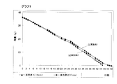
結果をグラフ1に示す。グラフ1は、実施例1,2の結果を各々曲線(i), (ii)として示す。
(4) 実験内容と結果
(A) 放置下での減量測定
(a) 本発明装置の性能
以下の長さの導出溝付きの垂下片を備えた薬液供給装置(実施例1,2)
実施形態1に示した導出溝付きの垂下片を備えた薬液供給装置を用い、垂下片の長さL(図8(b)参照)を以下の寸法としたものを用いて放置下での減量測定を行なった。なお、長さLは、流出孔428の下縁から、垂下片430の下端までの長さである。
・実施例1:L=12mm
・実施例2:L=17mm
結果をグラフ1に示す。グラフ1は、実施例1,2の結果を各々曲線(i), (ii)として示す。
グラフに見るとおり、薬液の量は、時間と共に着実に減少しており、垂下片が長いほど薬液量の減少速度が速くなっており、導出溝が長くなると、薬液の滴下量が増えることを示している。
(b) 比較例の性能(比較例1,2,3)
比較例として、実施例1と同じ形状及び寸法であり表面が平坦な垂下片(導出溝なし)を備えた薬液供給装置(比較例1)、垂下片が実施形態に示す形状のもので上下方向の長さが3mmのもの(比較例2)及び10mmのもの(比較例3)である薬液供給装置を用いて放置下での減量測定を行なった。導出溝の形状及び本数は実施形態と同じである。
(b) 比較例の性能(比較例1,2,3)
比較例として、実施例1と同じ形状及び寸法であり表面が平坦な垂下片(導出溝なし)を備えた薬液供給装置(比較例1)、垂下片が実施形態に示す形状のもので上下方向の長さが3mmのもの(比較例2)及び10mmのもの(比較例3)である薬液供給装置を用いて放置下での減量測定を行なった。導出溝の形状及び本数は実施形態と同じである。
実験の結果をグラフ2に示す。グラフ2は、比較例1,2,3の結果を各々曲線(iii),(iv), (v)として示し、参考のため実施例1の結果(曲線(i) )を並べて示す。
グラフに見るとおり、比較例1,2では、薬液供給装置からは、薬液が僅かしか排出されず、比較例3では、ある程度の量が排出されるが、薬液の効果を必要程度得るには不十分である。垂下片が平坦面のものにおいても薬液が僅かに減少しているのは、緩衝室等により室温の変化に対する緩衝作用が機能し、そのときの薬液の流動に伴って僅かな量が流出したものと考えられ、より微量ではあるが、薬液保持体に流出している薬液の乾燥や香料の揮散、重量測定時の衝撃等による減量も影響していると考えられる。
(c) 薬液粘度との関係(実施例3,4)
導出溝長さの適正値に薬液の粘度がどのように関係するかを調べるために、粘度の異なる薬液を用い、垂下片として以下の寸法の矩形板のものを用いて放置下での減量測定を行なった。この薬液は、粘度が25℃において80mPa・s、5℃において305mPa・sのものを用いた。薬液の処方及び粘度の測定方法は上述したものと同じである。
・実施例3:L=12mm
・実施例4:L=17mm
グラフ3に、実施例3,4の結果を各々曲線(vi), (vii)として示す。グラフ3と先のグラフ1の実施例1,2の結果(垂下片の長さ12mm、17mm;曲線(i), (ii))とを比べると明らかなとおり、薬液の粘度が変わっても維持性能に大きな変化は生じていない。
(c) 薬液粘度との関係(実施例3,4)
導出溝長さの適正値に薬液の粘度がどのように関係するかを調べるために、粘度の異なる薬液を用い、垂下片として以下の寸法の矩形板のものを用いて放置下での減量測定を行なった。この薬液は、粘度が25℃において80mPa・s、5℃において305mPa・sのものを用いた。薬液の処方及び粘度の測定方法は上述したものと同じである。
・実施例3:L=12mm
・実施例4:L=17mm
グラフ3に、実施例3,4の結果を各々曲線(vi), (vii)として示す。グラフ3と先のグラフ1の実施例1,2の結果(垂下片の長さ12mm、17mm;曲線(i), (ii))とを比べると明らかなとおり、薬液の粘度が変わっても維持性能に大きな変化は生じていない。
したがって、導出溝の長さが10mmを超えると薬液の継続的流出が確保されるというのは、薬液の粘度に関わりなく言えることが明らかである。
(B) 使用状況下での減量測定
実施例1,2及び比較例1の薬液供給装置を用い、使用状況下での減量測定を行なった。結果をグラフ4に示す。グラフ4は、実施例1,2の装置を用いたものを各々曲線(viii),
(ix)、比較例1,2の装置を用いたものを各々曲線(x), (xi)として示している。このグラフでは、横軸をフラッシュ回数としている。グラフに見るとおり、実施例のものは双方に大きな差はなくほぼ一定で順調な減量を示すのに対し、比較例1,2では、(A)の放置下の試験結果同様に減量があまり見られない。これは、比較例1では垂下片に導出溝がなく、比較例2では垂下片及び導出溝が短い結果、流出口の下端開口に達した薬液が垂下片の面に導出されないことに起因している。特に、この薬液供給装置は、便器のリムに取り付けられるタイプであるので、ガイドプレートを設けて洗浄水流を妨げない範囲で洗浄水をガイドプレート上に導くようにしているため、通常の使用状態では垂下片自体が直接洗浄水に接触し難い構造となっている。したがって、これら比較例のように、薬液が垂下片からガイドプレートへ移行しない場合は、フラッシュによって減量が促進されるようなこともなく、使用上、機能しない。一方、実施例の容器は、前述の通り放置下においても薬液は着実に減量する上、フラッシュをした場合にも順調に薬液が減量し使用に適した容器であることが示されている。
(5) まとめ
以上の実験から、本発明の実施例では、放置下においても薬液の継続的な供給が確保されるという、比較例からは得られない効果を奏することが明らかである。したがって、実施例の薬液供給装置は、便器内の洗浄水に薬液を混入させ得ると共に、洗浄水に接しない位置に取り付けられても機能を発揮し得る。
(B) 使用状況下での減量測定
実施例1,2及び比較例1の薬液供給装置を用い、使用状況下での減量測定を行なった。結果をグラフ4に示す。グラフ4は、実施例1,2の装置を用いたものを各々曲線(viii),
(ix)、比較例1,2の装置を用いたものを各々曲線(x), (xi)として示している。このグラフでは、横軸をフラッシュ回数としている。グラフに見るとおり、実施例のものは双方に大きな差はなくほぼ一定で順調な減量を示すのに対し、比較例1,2では、(A)の放置下の試験結果同様に減量があまり見られない。これは、比較例1では垂下片に導出溝がなく、比較例2では垂下片及び導出溝が短い結果、流出口の下端開口に達した薬液が垂下片の面に導出されないことに起因している。特に、この薬液供給装置は、便器のリムに取り付けられるタイプであるので、ガイドプレートを設けて洗浄水流を妨げない範囲で洗浄水をガイドプレート上に導くようにしているため、通常の使用状態では垂下片自体が直接洗浄水に接触し難い構造となっている。したがって、これら比較例のように、薬液が垂下片からガイドプレートへ移行しない場合は、フラッシュによって減量が促進されるようなこともなく、使用上、機能しない。一方、実施例の容器は、前述の通り放置下においても薬液は着実に減量する上、フラッシュをした場合にも順調に薬液が減量し使用に適した容器であることが示されている。
(5) まとめ
以上の実験から、本発明の実施例では、放置下においても薬液の継続的な供給が確保されるという、比較例からは得られない効果を奏することが明らかである。したがって、実施例の薬液供給装置は、便器内の洗浄水に薬液を混入させ得ると共に、洗浄水に接しない位置に取り付けられても機能を発揮し得る。
1 薬液容器
2 装置本体
3 吊掛部材
4 薬液供給機構
11 排出口(薬剤容器)
21 ガイドプレート
412 連通管(薬液通路)
414 固定管(薬液通路)
424 案内管(薬液通路)
426 案内溝(薬液通路)
427 延長路(薬液通路)
428 流出孔
430 垂下片
435 導出溝
R リム
2 装置本体
3 吊掛部材
4 薬液供給機構
11 排出口(薬剤容器)
21 ガイドプレート
412 連通管(薬液通路)
414 固定管(薬液通路)
424 案内管(薬液通路)
426 案内溝(薬液通路)
427 延長路(薬液通路)
428 流出孔
430 垂下片
435 導出溝
R リム
Claims (7)
- 便器のリムに取り付けられる薬液供給装置であって、
薬液容器を支持する装置本体と、
該装置本体に設けられ、薬液容器の排出口に接続され薬液を該排出口から導いて排出する薬液排出機構と、
前記装置本体を便器のリムに吊り掛けるための吊掛部材と、を備え、
前記薬液排出機構は、薬液容器の排出口への連通部から薬液を導き下方の流出孔から排出するように上下方向に延びた薬液通路と、前記流出孔の開口縁に当接又は近接する位置から下方へ延びた垂下片とを備え、
該垂下片には、毛管作用により前記流出孔から薬液を継続的に導出して該垂下片から下方へ排出させる導出溝が形成されていることを特徴とする薬液供給装置。 - 前記導出溝が、前記垂下片の上端から下方へ10mmを超える長さで延びていることを特徴とする請求項1に記載の薬液供給装置。
- 前記導出溝から排出される薬液を受け、便器内を流れる洗浄水に接触したときに薬液を洗浄水を該洗浄水と共に流出させるガイドプレートをさらに備えていることを特徴とする請求項1又は2に記載の薬液供給装置。
- 前記ガイドプレートが前記垂下片の下方の位置から前記吊掛部材の方へ延びていることを特徴とする請求項3に記載の薬液供給装置。
- 前記ガイドプレートが、垂下片の下方の位置から吊掛部材の方へ行くにしたがって下降するように傾斜していることを特徴とする請求項4に記載の薬剤供給具。
- 前記ガイドプレートの上面には毛管作用により薬液を溝内に導く拡張溝が形成されていることを特徴とする請求項3から5のいずれかに記載の薬液供給装置。
- 前記ガイドプレートには、前記垂下片から該ガイドプレート上に供給された薬液を通過させて下方へ排出するための透孔が形成されていることを特徴とする請求項3から6のいずれかに記載の薬液供給装置。
Applications Claiming Priority (2)
| Application Number | Priority Date | Filing Date | Title |
|---|---|---|---|
| JP2008094394 | 2008-03-31 | ||
| JP2008-094394 | 2008-03-31 |
Publications (1)
| Publication Number | Publication Date |
|---|---|
| WO2009123239A1 true WO2009123239A1 (ja) | 2009-10-08 |
Family
ID=41135607
Family Applications (1)
| Application Number | Title | Priority Date | Filing Date |
|---|---|---|---|
| PCT/JP2009/056753 Ceased WO2009123239A1 (ja) | 2008-03-31 | 2009-03-31 | 薬液供給装置 |
Country Status (2)
| Country | Link |
|---|---|
| JP (1) | JP5665279B2 (ja) |
| WO (1) | WO2009123239A1 (ja) |
Citations (4)
| Publication number | Priority date | Publication date | Assignee | Title |
|---|---|---|---|---|
| JP2003517123A (ja) * | 1999-12-14 | 2003-05-20 | エス.シー. ジョンソン アンド サン、インコーポレイテッド | 液吐出便器リム取付け式便器クリーナ |
| JP2005515323A (ja) * | 2001-11-19 | 2005-05-26 | サラ リー/デーイー エヌ.ヴェー | 便器ケア作用を有している装置 |
| JP2005533947A (ja) * | 2002-07-19 | 2005-11-10 | エス.シー. ジョンソン アンド サン、インコーポレイテッド | 便器のリムに取付けられる延出板付きトイレクリーナ |
| JP2006283539A (ja) * | 2005-03-31 | 2006-10-19 | Kobayashi Pharmaceut Co Ltd | 薬液供給装置 |
-
2009
- 2009-03-31 WO PCT/JP2009/056753 patent/WO2009123239A1/ja not_active Ceased
- 2009-03-31 JP JP2009085737A patent/JP5665279B2/ja active Active
Patent Citations (4)
| Publication number | Priority date | Publication date | Assignee | Title |
|---|---|---|---|---|
| JP2003517123A (ja) * | 1999-12-14 | 2003-05-20 | エス.シー. ジョンソン アンド サン、インコーポレイテッド | 液吐出便器リム取付け式便器クリーナ |
| JP2005515323A (ja) * | 2001-11-19 | 2005-05-26 | サラ リー/デーイー エヌ.ヴェー | 便器ケア作用を有している装置 |
| JP2005533947A (ja) * | 2002-07-19 | 2005-11-10 | エス.シー. ジョンソン アンド サン、インコーポレイテッド | 便器のリムに取付けられる延出板付きトイレクリーナ |
| JP2006283539A (ja) * | 2005-03-31 | 2006-10-19 | Kobayashi Pharmaceut Co Ltd | 薬液供給装置 |
Also Published As
| Publication number | Publication date |
|---|---|
| JP5665279B2 (ja) | 2015-02-04 |
| JP2009264100A (ja) | 2009-11-12 |
Similar Documents
| Publication | Publication Date | Title |
|---|---|---|
| JP4145046B2 (ja) | 改良された液吐出便器クリーナ | |
| JP4116432B2 (ja) | 複数のトイレケア作用を有する装置 | |
| JP5665279B2 (ja) | 薬液供給装置 | |
| JP5606010B2 (ja) | 薬液供給装置 | |
| JP5506217B2 (ja) | 薬液供給装置 | |
| JP5578802B2 (ja) | 薬液供給装置 | |
| JP5213784B2 (ja) | 薬液供給装置 | |
| HUP0402248A2 (hu) | Folyékony aktív anyag adagoló wc-csészéhez | |
| JP5424605B2 (ja) | 薬液供給装置 | |
| JP5334673B2 (ja) | 薬液供給装置 | |
| JP5601767B2 (ja) | 薬液供給装置 | |
| JP5164482B2 (ja) | 薬液供給装置 | |
| JP5448349B2 (ja) | 薬液供給装置 | |
| JP5478002B2 (ja) | 通液構造及び該通液構造を備えた薬液供給装置 | |
| JP5121536B2 (ja) | 薬液供給装置 | |
| JP5030712B2 (ja) | 薬液供給装置 | |
| JP5448421B2 (ja) | 薬液供給装置 | |
| JP2004300665A (ja) | 薬液供給具 | |
| JP2020105725A (ja) | 薬液供給装置 | |
| WO2013047681A1 (ja) | 薬液供給装置 | |
| JP2009084803A (ja) | 薬液供給装置 | |
| JP2020105723A (ja) | 薬液供給装置 | |
| JP2020105724A (ja) | 薬液供給装置 |
Legal Events
| Date | Code | Title | Description |
|---|---|---|---|
| 121 | Ep: the epo has been informed by wipo that ep was designated in this application |
Ref document number: 09728201 Country of ref document: EP Kind code of ref document: A1 |
|
| NENP | Non-entry into the national phase |
Ref country code: DE |
|
| 122 | Ep: pct application non-entry in european phase |
Ref document number: 09728201 Country of ref document: EP Kind code of ref document: A1 |