WO2009122614A1 - Dispositif de filtration tournant - Google Patents
Dispositif de filtration tournant Download PDFInfo
- Publication number
- WO2009122614A1 WO2009122614A1 PCT/JP2008/071394 JP2008071394W WO2009122614A1 WO 2009122614 A1 WO2009122614 A1 WO 2009122614A1 JP 2008071394 W JP2008071394 W JP 2008071394W WO 2009122614 A1 WO2009122614 A1 WO 2009122614A1
- Authority
- WO
- WIPO (PCT)
- Prior art keywords
- liquid
- rotating container
- container
- rotary
- peripheral surface
- Prior art date
Links
Images


Classifications
-
- B—PERFORMING OPERATIONS; TRANSPORTING
- B01—PHYSICAL OR CHEMICAL PROCESSES OR APPARATUS IN GENERAL
- B01D—SEPARATION
- B01D33/00—Filters with filtering elements which move during the filtering operation
- B01D33/27—Filters with filtering elements which move during the filtering operation with rotary filtering surfaces, which are neither cylindrical nor planar, e.g. helical surfaces
- B01D33/275—Filters with filtering elements which move during the filtering operation with rotary filtering surfaces, which are neither cylindrical nor planar, e.g. helical surfaces using contiguous impervious surfaces
-
- B—PERFORMING OPERATIONS; TRANSPORTING
- B01—PHYSICAL OR CHEMICAL PROCESSES OR APPARATUS IN GENERAL
- B01D—SEPARATION
- B01D33/00—Filters with filtering elements which move during the filtering operation
- B01D33/06—Filters with filtering elements which move during the filtering operation with rotary cylindrical filtering surfaces, e.g. hollow drums
- B01D33/067—Construction of the filtering drums, e.g. mounting or sealing arrangements
-
- B—PERFORMING OPERATIONS; TRANSPORTING
- B01—PHYSICAL OR CHEMICAL PROCESSES OR APPARATUS IN GENERAL
- B01D—SEPARATION
- B01D33/00—Filters with filtering elements which move during the filtering operation
- B01D33/06—Filters with filtering elements which move during the filtering operation with rotary cylindrical filtering surfaces, e.g. hollow drums
- B01D33/073—Filters with filtering elements which move during the filtering operation with rotary cylindrical filtering surfaces, e.g. hollow drums arranged for inward flow filtration
Definitions
- the present invention relates to a rotary filtration device for filtering a liquid in which solid particles are mixed.
- Rotating filtration devices are used to capture and recover solid particles from liquids in, for example, recycling processing of polishing liquids in metal processing equipment, waste liquid processing in food factories, and sewage processing in sewage treatment plants.
- a cylindrical rotary container arranged so as to be immersed in a liquid and having a peripheral surface formed of a wire mesh, and a granular filter medium filled in the rotary container are provided.
- a fluid filtration device including a filter tank body, a water collecting pipe that is coaxially disposed in the filter tank body and sucks water in the filter tank body, and a motor that rotationally drives the filter tank body about an axis. ing.
- liquid is caused to flow from the outer periphery into the filter tank body by the operation of a pump connected to a water collection pipe, and the suspended solids, which are small-sized solid particles, are used as a filter medium.
- the water is captured and filtered, and the filtered water is discharged from the water collecting pipe to the outside.
- it is necessary to perform a washing operation of the filter medium in order to remove suspended substances accumulated in the filter medium. That is, the filter tank body is rotationally driven by a motor to stir the filtering material, to separate suspended substances trapped between the filtering materials and on the surface of the filtering material, and the separated suspended substances are separated from the peripheral surface of the rotating container. It is discharged out of the filter tank body through a wire mesh.
- patent document 2 it is formed by the double cylinder which has the outer cylinder and the inner cylinder which were arrange
- a rotary filtration device including means and a cleaning nozzle that is disposed above the rotary container and injects a cleaning liquid onto a filter medium in the rotary container.
- the cleaning nozzle is formed so as to be able to reciprocate along a rail disposed in parallel with the axis above the rotating container. Further, in the inner cylinder of the rotating container, there are provided a liquid collection container for receiving the washing liquid after washing the filter medium, and a guide tube for guiding the washing liquid after washing from the liquid collection container into the liquid tank.
- the liquid supplied to the liquid tank is caused to flow into the rotary container as the water level in the liquid tank rises, and the suspended matter is captured and filtered by the filter medium. Then, the liquid is discharged to the outside by the drainage means and the filtration operation is performed. After the filtration operation is performed for a predetermined period, the filter medium is washed. That is, the rotating container is rotated by the rotating means so that the portion immersed in the liquid is opposed to the cleaning nozzle, and the cleaning nozzle is reciprocated in the axial direction while spraying the cleaning liquid from the cleaning nozzle to clean the filter medium.
- any of the conventional filtration devices described above since the peripheral surface of the rotating container is formed of a net, large-sized solid particles that do not pass through the net adhere to the peripheral surface of the rotating container, and the attached solid particles As a result, the flow of the liquid is hindered and the filtration efficiency is lowered.
- the solid particles adhering to the rotating container are often fixed to the net by the flow of liquid passing through the rotating container, and it is difficult to remove the fixed solid particles by a washing operation in any conventional filtration device. It was.
- the rotary filtration device disclosed in Patent Document 2 can remove solid particles adhering to the rotary container by a cleaning operation.
- a driving mechanism for the cleaning nozzle, a supply mechanism for the cleaning liquid, and the like are required, the apparatus configuration is complicated, and there is a problem that the manufacturing cost increases.
- a cleaning liquid for performing a cleaning operation is required, there is a problem in that maintenance costs also increase.
- the cleaning operation requires a considerable amount of time because the rotation of the rotating container and the cleaning of the portion facing the cleaning nozzle are alternately repeated, the operation time of the filtration operation is reduced and the operation efficiency is lowered. There was also.
- the present invention has been made in view of the above circumstances, can prevent the solid particles from adhering to the rotating container, and can be manufactured at a relatively low cost with a simple structure, low maintenance costs, and good operating efficiency.
- An object of the present invention is to provide a simple rotary filtration device.
- a rotary filtration device includes a liquid tank to which a liquid to be filtered is supplied, and a filter medium that is arranged to be able to rotate in the liquid tank and filters the liquid.
- Rotation having a substantially cylindrical rotating container with a built-in container, a discharge unit for discharging the liquid filtered by the filter medium from the rotating container to the outside of the liquid tank, and a driving unit for rotating the rotating container.
- the rotary container is provided with a plurality of liquid circulation openings that are open in a direction opposite to the rotation direction on a peripheral surface.
- the liquid is supplied to the liquid tank, and the rotary container is rotationally driven by the drive unit.
- the liquid in the liquid tank flows into the rotating container from the plurality of liquid circulation openings of the rotating container that is driven to rotate.
- the liquid that has flowed into the rotating container is filtered by the filter medium, and the filtered liquid is discharged from the rotating container to the outside of the liquid tank by the discharge unit. Since the liquid circulation opening of the rotating container is opened toward the side opposite to the rotating direction of the rotating container, it is larger than the rotating container in which the net is provided on the peripheral surface as in the prior art. Solid particles having a diameter are not sucked from the liquid circulation opening. Therefore, large diameter solid particles do not adhere to the rotating container, and the clogging frequency can be reduced. As a result, the flow of the liquid is not hindered by the attached solid particles, and it is possible to prevent a decrease in filtration efficiency.
- the rotary container has a plurality of plate members arranged in a circumferential direction having at least a part of an inclined surface inclined with respect to a tangential direction of the circumferential surface.
- the liquid flow opening is formed between the plurality of plate members.
- the rotating container includes a plurality of plate members arranged in a circumferential direction having at least a part of an inclined surface inclined with respect to a tangential direction of the peripheral surface, and a liquid is provided between the plurality of plate members.
- a distribution opening is formed.
- the plate member in the second aspect of the invention, includes a peripheral surface portion extending in a tangential direction of the peripheral surface of the rotary container, and between the peripheral surface portion and the peripheral surface of the rotary container. Between the tip of the peripheral surface portion of the one plate member and the inclined surface portion of another plate member adjacent in the counter-rotating direction of the rotating container. The liquid circulation opening is formed.
- the plate member of the rotating container includes a peripheral surface portion extending in the tangential direction of the peripheral surface, and an inclined surface portion provided between the peripheral surface portion and the peripheral surface of the rotating container.
- a slit-like liquid flow opening is formed between the tip of the peripheral surface portion of the plate member and the inclined surface portion of another plate member adjacent in the counter-rotating direction of the rotating container.
- the rotary filtration device is characterized in that, in any one of the first to third inventions, a precipitate discharge pipe for discharging the precipitate is connected to a lower portion of the liquid tank. To do.
- the large diameter solid which remained in the liquid and adhered to the lower part of the liquid tank without adhering to a rotation container by connecting the sediment discharge pipe
- Precipitates such as particles can be discharged to the outside through the precipitate discharge pipe.
- the liquid flow opening of the rotating container is opened toward the opposite side to the rotating direction of the rotating container, so that compared with a rotating container having a mesh provided on the peripheral surface as in the prior art.
- the large-diameter solid particles contained in the liquid are not sucked from the liquid circulation opening. Therefore, large diameter solid particles do not adhere to the rotating container, and the clogging frequency can be reduced. As a result, the flow of the liquid is not hindered by the attached solid particles, and it is possible to prevent a decrease in filtration efficiency.
- (A) is a side view of the rotary filter apparatus which concerns on embodiment of this invention
- (b) is a front view of the rotary filter apparatus which concerns on embodiment of this invention.
- It is a plane sectional view of a rotary filtration device concerning an embodiment of the invention.
- It is a perspective view of the rotation container of the rotary filtration apparatus which concerns on embodiment of this invention.
- It is a fragmentary sectional view of the rotation axis perpendicular direction of the rotation container of the rotation filtration device concerning an embodiment of the invention.
- the present embodiment is a rotary filtration device that is used by being connected to a polishing device as a metal processing device, filtering the polishing liquid after polishing discharged from the polishing device, and polishing debris and polishing as solid particles
- a polishing device as a metal processing device
- polishing debris and polishing as solid particles
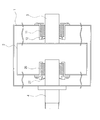
- FIG. 1 (a) is a side view of a rotary filtration device according to an embodiment of the present invention
- FIG. 1 (b) is a front view of the rotary filtration device according to an embodiment of the present invention
- FIG. 2 is a plan sectional view of the rotary filtration device according to the embodiment of the present invention.
- a rotary filtration device includes a housing 1 that is a substantially rectangular parallelepiped liquid tank, and a generally cylindrical housing that can be rotated within the housing 1.
- a shaped rotating container 2 a drive shaft 3 fixed to one end surface of the rotating container 2 and projecting from the back surface of the housing 1, and polishing after filtration in the rotating container 2 through the other end surface of the rotating container 2
- a filtrate discharge pipe 4 that is a discharge part for discharging the liquid to the outside of the housing 1, a motor 5 connected to the drive shaft 3, a sediment discharge pipe 6 connected to the bottom surface of the housing 1, and a sediment discharge pipe 6 is provided with a butterfly valve 7 interposed.
- the housing 1 is formed in an arc shape concentric with the rotating container 2 at the lower portion, as shown in FIG.
- the lower end of the housing 1 is formed in a tapered shape with a reduced cross-sectional area, and is connected to the sediment discharge pipe 6.
- a through hole is provided in the front and back of the housing 1, and a wood bearing 11 for supporting the drive shaft 3 is provided adjacent to the through hole in the back as shown in FIG.
- a rotary shaft seal 12 that seals between the outer peripheral surface of the drive shaft 3 and the wood bearing 11 is provided adjacent to the inside of the housing 1 of the wood bearing 11.
- a filtrate discharge pipe 4 is fixed in a through hole on the front surface of the housing 1 in a state where the filtrate discharge pipe 4 is inserted.
- An inflow pipe 13 through which a polishing liquid is guided from the polishing apparatus is provided at an upper portion of the side surface of the housing 1, and a distal end portion of the inflow pipe 13 is bent in the housing 1.
- the housing 1 has a sealed structure in order to maintain the pressure of the polishing liquid fed from the polishing apparatus.
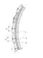
- FIG. 3 is a perspective view of the rotary container of the rotary filtration device according to the embodiment of the present invention.
- FIG. 4 is a partial cross-sectional view in the direction perpendicular to the rotation axis of the rotary container of the rotary filtration device according to the embodiment of the present invention.
- the rotary container 2 of the rotary filtration device according to the present embodiment includes two disk-like end face plates 21 and 21 that form cylindrical end faces, and an outer peripheral side of each end face plate 21.
- a filter medium 25 formed by forming a stainless steel mesh into a cylindrical shape is accommodated on the inner diameter side of the plurality of plate members 24, 24,.
- the drive shaft 3 is fixed to the outer surface of one end face plate 21, while the other end face plate 21 is provided with a through hole through which the filtrate discharge pipe 4 is inserted.
- a wood bearing 26 is provided inside the other end face plate 21 so as to be adjacent to the through-hole, and the other end face plate 21 side of the rotary container 2 is disposed through the wood bearing 26.
- the filtrate discharge pipe 4 is supported.
- a rotary shaft seal 27 that seals between the outer peripheral surface of the filtrate discharge pipe 4 and the wood bearing 26 is provided outside the rotary container 2 of the wood bearing 26.
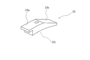
- FIG. 5 is a perspective view of the bracket of the rotary container of the rotary filtration device according to the embodiment of the present invention.
- the bracket 23 is formed of a plate-like body having a flat trapezoidal cross section, a bottom surface 23c curved so as to be in close contact with the outer peripheral surface of the annular frame 22, a top surface 23a substantially parallel to the bottom surface 23c, And an inclined surface 23b inclined at an angle of 10 to 20 ° with respect to the surface 23a.
- the bracket 23 is fixed to the annular frame 22 so that the inclined surface 23b is positioned in the rotational direction with respect to the top surface 23a.
- the edge of the top surface 23a of the bracket 23 protrudes in a direction opposite to the rotation direction than the edge of the bottom surface 23c.
- the plate member 24 has an elongated rectangular shape extending in parallel with the rotation axis, and is fixed by a screw 28 that passes through the bracket 23 and is screwed to the annular frame 22. ing.
- the plate member 24 has a peripheral surface portion 24 a that is substantially parallel to the tangential direction of the peripheral surface of the rotating container 2, and an inclined portion 24 b that is inclined with respect to the tangential direction of the peripheral surface of the rotating container 2.
- the inclined portion 24b of the plate member 24 is inclined at an angle of 10 to 20 ° with respect to the peripheral surface portion 24a.
- the peripheral surface portion 24a and the inclined portion 24b are formed to have substantially the same length in the circumferential direction.
- the plate member 24 is fixed to the bracket 23 so that the peripheral surface portion 24 a is along the top surface 23 a of the bracket 23 and the inclined portion 24 b is along the inclined surface 23 b of the bracket 23.
- the plate member 24 is fixed so that the inclined portion 24b is positioned in the rotational direction of the rotating container 2 relative to the peripheral surface portion 24a, and the inclined portion 24b is inclined inward in the radial direction as it goes in the rotational direction.
- the plurality of plate members 24, 24,... Fixed to the bracket 23 are inclined portions 24b, 24b,... And circumferential surface portions in the circumferential direction between the adjacent plate members 24, 24,. Are overlapped with each other, and the end portions of the peripheral surface portions 24a, 24a,...
- the filtrate discharge pipe 4 that is fixed through the through-hole in the front of the housing 1 and supports the rotary container 2 so as to be able to rotate inside the housing 1 has a polishing liquid at the tip in the rotary container 2. An opening is provided for inhaling and discharging to the outside.
- the filtrate discharge pipe 4 is connected to a liquid feed pump (not shown), and the filtered polishing liquid in the rotary container 2 is sucked by the liquid feed pump and discharged to the outside of the rotary filtration device.
- the discharged polishing liquid is returned to the polishing apparatus and reused for the polishing process.
- the polishing liquid is configured to circulate between the polishing apparatus and the rotary filtration apparatus.
- the operation of the rotary filtration device having the above configuration will be described.
- the motor 5 of the rotary filtration apparatus is started, and the rotary container 2 is rotationally driven as indicated by an arrow B via the drive shaft 3.
- a liquid feed pump (not shown) is activated, and the inside of the housing 1 is sucked through the filtrate discharge pipe 4.
- the polishing liquid used for polishing the workpiece by the polishing apparatus is guided into the housing 1 through the inflow pipe 13 in a state in which solid particles such as polishing scraps of the workpiece, abrasives, and grinding stone scraps are contained.
- the polishing liquid guided to the inflow pipe 13 is discharged into the housing 1 from the opening of the inflow pipe 13 and flows down while contacting the peripheral surface of the rotating container 2.
- the direction in which the polishing liquid flows is opposite to the direction in which the peripheral surface of the rotating container 2 rotates.
- the polishing liquid that has flowed down the peripheral surface of the rotating container 2 is stored at the bottom of the housing 1, the liquid level in the housing 1 rises, and the lower half of the rotating container 2 is immersed in the polishing liquid.
- the filtered polishing liquid is sucked from the tip of the filtrate discharge pipe 4 that opens inside the filter medium 25 of the rotary container 2, and is discharged out of the rotary filtration device through the filtrate discharge pipe 4.
- mainly large-diameter solid particles that do not flow into the liquid circulation opening 29 settle on the bottom of the housing 1 and are collected at the tapered lower end.
- the solid particles collected at the lower end of the housing 1 are discharged to the outside through the sediment discharge pipe 6 when the butterfly valve 7 is opened.
- the liquid flow opening 29 of the rotating container 2 faces in the direction opposite to the rotating direction of the rotating container 2, polishing is performed in comparison with a rotating container in which a net having a conventional opening is provided on the peripheral surface.
- Large diameter solid particles contained in the liquid are hardly sucked into the liquid circulation opening 29.
- the plate member 24 arranged on the outer periphery of the rotating container 2 rotates, a centrifugal force acts on the solid particles from the inclined portion 24b of the plate member 24, and the large-diameter solid particles are effectively circulated through the liquid. It can be moved away from the opening 29. Therefore, the large-diameter solid particles do not adhere to the liquid circulation opening 29, the flow of the polishing liquid in the liquid circulation opening 29 is not hindered, and it becomes possible to prevent the filtration efficiency of the polishing liquid from being lowered. .
- the rotary filtration device since there is no need for a cleaning nozzle drive mechanism, a cleaning liquid supply mechanism, and the like as in the prior art, it is possible to prevent solid particles from adhering to the rotary container 2. Thus, a rotary filtration device that can be used with a simple configuration can be provided at low cost. Moreover, since the effort which removes the solid particle adhering to the rotation container 2 can also be reduced, a maintenance frequency can be reduced and a rotary filtration apparatus with favorable operation efficiency can be provided.
- the rotary filtration device according to the present embodiment, it is possible to prevent solid particles from adhering to the liquid circulation opening 29, so that the flow loss in the liquid circulation opening 29 is effectively stably kept low. And the above-mentioned problems can be effectively prevented. That is, the processing accuracy of the polishing apparatus can be stably and satisfactorily maintained without increasing the cost of the polishing apparatus, the rotary filtration apparatus, or the like.
- the bent plate member 24 having the peripheral surface portion 24a and the inclined portion 24b is arranged on the peripheral surface of the rotating container 2, but the flat plate member is inclined with respect to the tangential direction. Needless to say, they may be arranged.
- the slit-shaped liquid circulation opening 29 is formed between the plate members 24 arranged on the peripheral surface of the rotary container 2, but the liquid circulation opening is limited to the slit shape. Instead, it may be formed in various forms such as a rectangular shape and a circular shape.
- the peripheral surface of the rotary container 2 is formed of a cylindrical plate material, a plurality of through holes are provided in the plate material, and the opening is directed to the edge of the provided through hole in the direction opposite to the rotation direction of the rotary container 2.
- a liquid-shaped opening 29 may be formed by attaching a shaped member.
- the rotary filtration device is used for filtering the polishing liquid discharged from the polishing device, but may be used for filtering the discharged liquid of other metal processing apparatuses.
- the rotary filtration device of the present invention can be applied to other uses such as waste liquid treatment in food factories and sewage treatment in sewage treatment plants, without being limited to waste liquid treatment of metal processing equipment.
Landscapes
- Chemical & Material Sciences (AREA)
- Chemical Kinetics & Catalysis (AREA)
- Filtration Of Liquid (AREA)
- Centrifugal Separators (AREA)
- Auxiliary Devices For Machine Tools (AREA)
Abstract
L'invention porte sur un dispositif de filtration tournant dans lequel des particules solides sont empêchées d'adhérer à un récipient tournant et qui a une structure simple, qui peut être fabriqué à un faible coût, qui peut être entretenu à un faible coût et qui a un bon rendement de fonctionnement. Le dispositif de filtration tournant a un boîtier (1) dans lequel un liquide de polissage est introduit par un tuyau d'entrée (13), le récipient tournant (2) ayant une forme cylindrique creuse circulaire et étant contenu dans le boîtier (1) et incorporant une matière de filtration (25), un tuyau (4) de décharge de liquide filtré doublant en tant qu'arbre tournant du récipient tournant (2) et faisant sortir le liquide de polissage filtré provenant de l'intérieur du récipient tournant (2), et un moteur (5) pour faire tourner le récipient tournant (2). Le récipient tournant (2) a des éléments de type plaques disposés sur la surface périphérique du récipient tournant et a également des ouvertures d'écoulement de liquide entre les éléments de type plaques. Le liquide de polissage rejeté à partir du tuyau d'entrée (13) s'écoule en descendant sur la surface périphérique du récipient tournant (2). Le récipient tournant (2) est entraîné en rotation tout en étant immergé dans le liquide de polissage contenu dans le boîtier (1). L'ouverture d'écoulement de liquide est ouverte dans la direction opposée à la direction de rotation du récipient tournant (2), et ceci réduit le degré d'adhérence des particules solides à l'ouverture d'écoulement de liquide.
Priority Applications (2)
| Application Number | Priority Date | Filing Date | Title |
|---|---|---|---|
| US12/935,020 US20110017656A1 (en) | 2008-03-31 | 2008-11-26 | Rotary filtration device |
| EP08873788A EP2277613A4 (fr) | 2008-03-31 | 2008-11-26 | Dispositif de filtration tournant |
Applications Claiming Priority (2)
| Application Number | Priority Date | Filing Date | Title |
|---|---|---|---|
| JP2008089477A JP4537468B2 (ja) | 2008-03-31 | 2008-03-31 | 回転濾過装置 |
| JP2008-089477 | 2008-03-31 |
Publications (1)
| Publication Number | Publication Date |
|---|---|
| WO2009122614A1 true WO2009122614A1 (fr) | 2009-10-08 |
Family
ID=41135026
Family Applications (1)
| Application Number | Title | Priority Date | Filing Date |
|---|---|---|---|
| PCT/JP2008/071394 WO2009122614A1 (fr) | 2008-03-31 | 2008-11-26 | Dispositif de filtration tournant |
Country Status (4)
| Country | Link |
|---|---|
| US (1) | US20110017656A1 (fr) |
| EP (1) | EP2277613A4 (fr) |
| JP (1) | JP4537468B2 (fr) |
| WO (1) | WO2009122614A1 (fr) |
Cited By (1)
| Publication number | Priority date | Publication date | Assignee | Title |
|---|---|---|---|---|
| CN113018954A (zh) * | 2021-03-05 | 2021-06-25 | 南宁兴科净医疗科技有限公司 | 一种分离式重金属废水处理系统 |
Families Citing this family (4)
| Publication number | Priority date | Publication date | Assignee | Title |
|---|---|---|---|---|
| CN107285499B (zh) * | 2017-08-13 | 2018-08-10 | 贾新奎 | 一种生活污水除油滤渣装置 |
| CN107413101A (zh) * | 2017-08-13 | 2017-12-01 | 贾新奎 | 一种自清洁饮用水净水机 |
| CN107433061A (zh) * | 2017-09-26 | 2017-12-05 | 贾新奎 | 一种并联式陶瓷净水器 |
| CN112126916B (zh) * | 2019-06-25 | 2023-03-24 | 富航智能科技(天津)有限公司 | 一种化学镍自动添加装置 |
Citations (7)
| Publication number | Priority date | Publication date | Assignee | Title |
|---|---|---|---|---|
| JPS474123Y1 (fr) * | 1969-06-19 | 1972-02-14 | ||
| JPS5667518A (en) * | 1979-11-09 | 1981-06-06 | Nippon Syst Apurikeeshiyon:Kk | Filter apparatus |
| JPS56139112A (en) | 1980-01-28 | 1981-10-30 | Celleco Ab | Device for filtering pulp |
| JPH10323510A (ja) | 1997-03-27 | 1998-12-08 | Mitsubishi Materials Corp | 軸心吐出式流体濾過装置及び方法 |
| JP2001120911A (ja) | 1999-10-29 | 2001-05-08 | Mitsubishi Materials Corp | 濾過材洗浄機能付回転濾過装置 |
| JP2001259309A (ja) * | 2000-03-16 | 2001-09-25 | Mitsubishi Kakoki Kaisha Ltd | 回転濾過機 |
| JP2004321893A (ja) * | 2003-04-23 | 2004-11-18 | Maezawa Ind Inc | ろ過装置 |
-
2008
- 2008-03-31 JP JP2008089477A patent/JP4537468B2/ja not_active Expired - Fee Related
- 2008-11-26 US US12/935,020 patent/US20110017656A1/en not_active Abandoned
- 2008-11-26 EP EP08873788A patent/EP2277613A4/fr not_active Withdrawn
- 2008-11-26 WO PCT/JP2008/071394 patent/WO2009122614A1/fr active Application Filing
Patent Citations (7)
| Publication number | Priority date | Publication date | Assignee | Title |
|---|---|---|---|---|
| JPS474123Y1 (fr) * | 1969-06-19 | 1972-02-14 | ||
| JPS5667518A (en) * | 1979-11-09 | 1981-06-06 | Nippon Syst Apurikeeshiyon:Kk | Filter apparatus |
| JPS56139112A (en) | 1980-01-28 | 1981-10-30 | Celleco Ab | Device for filtering pulp |
| JPH10323510A (ja) | 1997-03-27 | 1998-12-08 | Mitsubishi Materials Corp | 軸心吐出式流体濾過装置及び方法 |
| JP2001120911A (ja) | 1999-10-29 | 2001-05-08 | Mitsubishi Materials Corp | 濾過材洗浄機能付回転濾過装置 |
| JP2001259309A (ja) * | 2000-03-16 | 2001-09-25 | Mitsubishi Kakoki Kaisha Ltd | 回転濾過機 |
| JP2004321893A (ja) * | 2003-04-23 | 2004-11-18 | Maezawa Ind Inc | ろ過装置 |
Non-Patent Citations (1)
| Title |
|---|
| See also references of EP2277613A4 * |
Cited By (1)
| Publication number | Priority date | Publication date | Assignee | Title |
|---|---|---|---|---|
| CN113018954A (zh) * | 2021-03-05 | 2021-06-25 | 南宁兴科净医疗科技有限公司 | 一种分离式重金属废水处理系统 |
Also Published As
| Publication number | Publication date |
|---|---|
| EP2277613A4 (fr) | 2011-11-30 |
| JP2009240892A (ja) | 2009-10-22 |
| US20110017656A1 (en) | 2011-01-27 |
| EP2277613A1 (fr) | 2011-01-26 |
| JP4537468B2 (ja) | 2010-09-01 |
Similar Documents
| Publication | Publication Date | Title |
|---|---|---|
| JP5626969B2 (ja) | 濾過材洗浄装置 | |
| EP3481527B1 (fr) | Un filtre à disque d'un filtre à disque avec double écran de présélection | |
| AU2020231174B2 (en) | Rotary disc filter having backwash guides | |
| EP3795228B1 (fr) | Dispositif de filtration | |
| JP5410656B2 (ja) | 濾過装置用の外付け濾過材洗浄装置 | |
| JP4537468B2 (ja) | 回転濾過装置 | |
| EP2921458B1 (fr) | Dispositif de séparation de solides d'eaux usées | |
| JP2004160432A (ja) | 濾過装置 | |
| JP4181440B2 (ja) | 濾過装置およびそれを用いた濾過方法 | |
| EP1683561B1 (fr) | Dispositif de filtration | |
| KR100583377B1 (ko) | 디스크 필터의 여재에 부착된 유기물 및 무기물 등의제거를 위한 약품세척장치 | |
| KR20160004499A (ko) | 수질 정화용 드럼스크린장치 | |
| US20090166283A1 (en) | Filter Device and Method for Purifying Polluted Liquids | |
| KR100380225B1 (ko) | 싸이클론식 연속여과기의 자동 역세 장치 | |
| JP4041588B2 (ja) | 濾過装置 | |
| JP2795581B2 (ja) | クーラント濾過装置 | |
| JP2021186735A (ja) | ろ過装置 | |
| JP7399525B1 (ja) | 濾過用ストレーナの自動洗浄システム | |
| JP2000202497A (ja) | 汚泥濾過濃縮装置 | |
| JP4550125B2 (ja) | クリーニング機構付き濾過装置 | |
| WO2024084989A1 (fr) | Dispositif de filtration | |
| JP2003225517A (ja) | 固液分離装置の洗浄方法 | |
| JP2002166110A (ja) | 固液分離装置 | |
| JP6375409B1 (ja) | クーラント濾過装置 | |
| JP2002166111A (ja) | 固液分離装置 |
Legal Events
| Date | Code | Title | Description |
|---|---|---|---|
| 121 | Ep: the epo has been informed by wipo that ep was designated in this application |
Ref document number: 08873788 Country of ref document: EP Kind code of ref document: A1 |
|
| DPE2 | Request for preliminary examination filed before expiration of 19th month from priority date (pct application filed from 20040101) | ||
| WWE | Wipo information: entry into national phase |
Ref document number: 12935020 Country of ref document: US |
|
| NENP | Non-entry into the national phase |
Ref country code: DE |
|
| WWE | Wipo information: entry into national phase |
Ref document number: 2008873788 Country of ref document: EP |