WO2009119337A1 - 画像処理装置、画像処理プログラム、画像処理システム及び画像処理方法 - Google Patents
画像処理装置、画像処理プログラム、画像処理システム及び画像処理方法 Download PDFInfo
- Publication number
- WO2009119337A1 WO2009119337A1 PCT/JP2009/054843 JP2009054843W WO2009119337A1 WO 2009119337 A1 WO2009119337 A1 WO 2009119337A1 JP 2009054843 W JP2009054843 W JP 2009054843W WO 2009119337 A1 WO2009119337 A1 WO 2009119337A1
- Authority
- WO
- WIPO (PCT)
- Prior art keywords
- image
- obstacle
- bird
- eye view
- eye
- Prior art date
- Legal status (The legal status is an assumption and is not a legal conclusion. Google has not performed a legal analysis and makes no representation as to the accuracy of the status listed.)
- Ceased
Links
Images



Classifications
-
- B—PERFORMING OPERATIONS; TRANSPORTING
- B60—VEHICLES IN GENERAL
- B60R—VEHICLES, VEHICLE FITTINGS, OR VEHICLE PARTS, NOT OTHERWISE PROVIDED FOR
- B60R1/00—Optical viewing arrangements; Real-time viewing arrangements for drivers or passengers using optical image capturing systems, e.g. cameras or video systems specially adapted for use in or on vehicles
- B60R1/20—Real-time viewing arrangements for drivers or passengers using optical image capturing systems, e.g. cameras or video systems specially adapted for use in or on vehicles
- B60R1/22—Real-time viewing arrangements for drivers or passengers using optical image capturing systems, e.g. cameras or video systems specially adapted for use in or on vehicles for viewing an area outside the vehicle, e.g. the exterior of the vehicle
- B60R1/23—Real-time viewing arrangements for drivers or passengers using optical image capturing systems, e.g. cameras or video systems specially adapted for use in or on vehicles for viewing an area outside the vehicle, e.g. the exterior of the vehicle with a predetermined field of view
- B60R1/27—Real-time viewing arrangements for drivers or passengers using optical image capturing systems, e.g. cameras or video systems specially adapted for use in or on vehicles for viewing an area outside the vehicle, e.g. the exterior of the vehicle with a predetermined field of view providing all-round vision, e.g. using omnidirectional cameras
-
- G—PHYSICS
- G06—COMPUTING OR CALCULATING; COUNTING
- G06T—IMAGE DATA PROCESSING OR GENERATION, IN GENERAL
- G06T15/00—Three-dimensional [3D] image rendering
- G06T15/10—Geometric effects
- G06T15/20—Perspective computation
-
- B—PERFORMING OPERATIONS; TRANSPORTING
- B60—VEHICLES IN GENERAL
- B60R—VEHICLES, VEHICLE FITTINGS, OR VEHICLE PARTS, NOT OTHERWISE PROVIDED FOR
- B60R2300/00—Details of viewing arrangements using cameras and displays, specially adapted for use in a vehicle
- B60R2300/10—Details of viewing arrangements using cameras and displays, specially adapted for use in a vehicle characterised by the type of camera system used
- B60R2300/105—Details of viewing arrangements using cameras and displays, specially adapted for use in a vehicle characterised by the type of camera system used using multiple cameras
-
- B—PERFORMING OPERATIONS; TRANSPORTING
- B60—VEHICLES IN GENERAL
- B60R—VEHICLES, VEHICLE FITTINGS, OR VEHICLE PARTS, NOT OTHERWISE PROVIDED FOR
- B60R2300/00—Details of viewing arrangements using cameras and displays, specially adapted for use in a vehicle
- B60R2300/30—Details of viewing arrangements using cameras and displays, specially adapted for use in a vehicle characterised by the type of image processing
- B60R2300/301—Details of viewing arrangements using cameras and displays, specially adapted for use in a vehicle characterised by the type of image processing combining image information with other obstacle sensor information, e.g. using RADAR/LIDAR/SONAR sensors for estimating risk of collision
-
- B—PERFORMING OPERATIONS; TRANSPORTING
- B60—VEHICLES IN GENERAL
- B60R—VEHICLES, VEHICLE FITTINGS, OR VEHICLE PARTS, NOT OTHERWISE PROVIDED FOR
- B60R2300/00—Details of viewing arrangements using cameras and displays, specially adapted for use in a vehicle
- B60R2300/30—Details of viewing arrangements using cameras and displays, specially adapted for use in a vehicle characterised by the type of image processing
- B60R2300/303—Details of viewing arrangements using cameras and displays, specially adapted for use in a vehicle characterised by the type of image processing using joined images, e.g. multiple camera images
-
- B—PERFORMING OPERATIONS; TRANSPORTING
- B60—VEHICLES IN GENERAL
- B60R—VEHICLES, VEHICLE FITTINGS, OR VEHICLE PARTS, NOT OTHERWISE PROVIDED FOR
- B60R2300/00—Details of viewing arrangements using cameras and displays, specially adapted for use in a vehicle
- B60R2300/60—Details of viewing arrangements using cameras and displays, specially adapted for use in a vehicle characterised by monitoring and displaying vehicle exterior scenes from a transformed perspective
- B60R2300/607—Details of viewing arrangements using cameras and displays, specially adapted for use in a vehicle characterised by monitoring and displaying vehicle exterior scenes from a transformed perspective from a bird's eye viewpoint
Definitions
- the present invention relates to an image processing system and an image processing method, and also relates to an image processing apparatus and an image processing program used in the image processing system.
- the present invention relates to a technique for generating bird's-eye view images from captured images of a plurality of cameras installed in a vehicle and synthesizing the bird's-eye view images.
- a system has been developed in which an in-vehicle camera (hereinafter simply referred to as a camera), which is an imaging device that monitors the rear of a vehicle that is likely to become a blind spot, is mounted on a car and the captured image is displayed on a screen of a car navigation device or the like. It is coming.
- a camera an in-vehicle camera
- a composite bird's-eye view image (hereinafter, referred to as an image of the situation of the entire circumference of the vehicle seen from above by combining the bird's-eye view images obtained by coordinate transformation of images obtained from a plurality of cameras as described above.
- An image processing system has been developed in which an all-around bird's-eye view image) is created and this all-around bird's-eye view image is displayed on the screen.
- this image processing system since the situation of the entire circumference of the vehicle can be presented to the driver as an image viewed from above, there is an advantage that the periphery of the vehicle can be grasped more easily by looking at the 360 ° blind spot.
- composite means that adjacent bird's-eye view images are moved and rotated with respect to each other so that the bird's-eye images can be consistent with each other and bonded together to form one bird's-eye view.
- an overlapping portion is generated between the bird's-eye views.
- Patent Document 1 describes a vehicle periphery monitoring device that uses a plurality of bird's-eye images (bird's-eye images) and displays a bird's-eye image that is synthesized.
- JP 2007-27948 A describes a vehicle periphery monitoring device that uses a plurality of bird's-eye images (bird's-eye images) and displays a bird's-eye image that is synthesized.
- an object of the present invention is to provide an “image processing apparatus” and an “image processing program” that improve the visibility of a composite bird's-eye view image. It is another object of the present invention to provide an “image processing system” and an “image processing method” using them.
- An image processing apparatus includes a viewpoint conversion unit that converts each of images captured by a plurality of imaging devices into a bird's-eye view image viewed from a virtual viewpoint, and each bird's-eye view image converted by the viewpoint conversion unit.
- An image processing apparatus including an image composition unit that synthesizes and generates a composite bird's-eye view image, the obstacle information extraction unit extracting obstacle information related to the obstacle based on the bird's-eye view image, and the obstacle information extraction
- An obstacle original image extraction unit that extracts an obstacle original image, which is an image including the obstacle, from an image captured by the imaging device based on the obstacle information extracted by a part, and the obstacle information Based on the obstacle information extracted by the extraction unit, an obstacle bird's-eye image detection unit that detects an obstacle bird's-eye image corresponding to the obstacle in the synthetic bird's-eye view image from the synthetic bird's-eye view image;
- a replacement processing unit that outputs an image obtained by replacing the obstacle bird's-eye image detected by the obstacle bird's-eye image detection unit with the obstacle original image extracted by the obstacle original image extraction unit as a replacement synthesized bird's-eye view image;
- a video data generation unit configured to generate video data for causing the display device to display the replacement composite bird's-eye
- the obstacle information extraction unit is an image of an overlapping region of the target bird's-eye view image that is the bird's-eye view image captured by the target imaging device that is at least two of the plurality of imaging devices.
- the obstacle information may be extracted by performing a difference process between the target bird's-eye view images.
- An image processing apparatus includes a viewpoint conversion unit that converts each of images captured by a plurality of imaging devices into a bird's-eye view image viewed from a virtual viewpoint, and each bird's-eye view image converted by the viewpoint conversion unit.
- An image processing apparatus including an image composition unit that synthesizes and generates a composite bird's-eye view image, the obstacle information extraction unit extracting obstacle information related to the obstacle based on the bird's-eye view image, and the obstacle information extraction
- An obstacle bird's-eye image detection unit that detects an obstacle bird's-eye image corresponding to the obstacle in the synthetic bird's-eye view image from the synthetic bird's-eye view image based on the obstacle information extracted by a unit; Based on the information on the obstacle bird's-eye image detected by the bird's-eye image detection unit, an obstacle original image that is an image including the obstacle is extracted from the image captured by the imaging device, and the obstacle
- a replacement processing unit that outputs, as a replacement composite bird's-eye view image, an image obtained by replacing the obstacle bird's-eye image detected by the object bird's-eye image detection unit with the obstacle original image, and the replacement composite bird's-eye view image output from the replacement processing unit
- a video data generation unit for generating video data for
- An image processing program includes a viewpoint conversion step of converting each of images captured by a plurality of imaging devices into a bird's eye view image viewed from a virtual viewpoint, and each bird's eye view image converted in the viewpoint conversion step.
- An image processing program for operating a computer as an image processing apparatus including an image synthesis step of generating a synthesized bird's-eye view image by combining, and extracting obstacle information relating to an obstacle based on the bird's-eye view image
- An obstacle original image that extracts an obstacle original image that is an image including the obstacle from the image captured by the imaging device based on the obstacle information extracted in the step and the obstacle information extraction step Based on the obstacle information extracted in the extraction step and the obstacle information extraction step, from the synthetic bird's-eye view image.
- the obstacle bird's-eye image detection step for detecting an obstacle bird's-eye image corresponding to the obstacle in the synthetic bird's-eye view image, and the obstacle bird's-eye image detected by the obstacle bird's-eye image detection unit is the obstacle
- a replacement processing step for outputting an image replaced with the obstacle original image extracted by the extraction unit as a replacement composite bird's-eye view image, and a video for displaying the replacement composite bird's-eye view image output from the replacement processing step on a display device And a video data generation step for generating data.
- An image processing system includes the above-described image processing device, the plurality of imaging devices, and the display device.
- the image processing method converts each of images captured by a plurality of imaging devices into a bird's-eye view image viewed from a virtual viewpoint, and generates a combined bird's-eye view image by combining the converted bird's-eye view images.
- An image processing method wherein obstacle information related to an obstacle is extracted based on the bird's eye view image, and an image including the obstacle is extracted from an image captured by the imaging device based on the extracted obstacle information.
- the obstacle original image is extracted, and the obstacle bird's-eye image corresponding to the obstacle in the synthetic bird's-eye view image is detected from the synthesized bird's-eye view image based on the extracted obstacle information, and the obstacle An image obtained by replacing the obstacle bird's eye image detected by the object bird's eye image detection unit with the obstacle original image extracted by the obstacle original image extraction unit is output as a replacement synthesized bird's eye view image and output. It generates video data for displaying the replacement composite bird's eye view image on the display device.
- the imaging device corresponds to a camera that captures a still image, a camera that captures a moving image, or the like.
- An obstacle refers to a three-dimensional object existing on the road surface or the ground, not a flat character or figure drawn on the road surface or the ground. Therefore, for example, creatures such as people, plants, and animals, vehicles such as cars, motorcycles, and bicycles, and artificial objects such as signs, fences, and posts are applicable as obstacles.
- the image is not limited to the meaning of the image in which the image of the captured subject is visualized.
- the image includes data of an image to be subjected to image processing such as viewpoint conversion or replacement. Is to be interpreted.
- the obstacle bird's-eye view image is not limited to the entire image as long as the obstacle is reflected, and may be a partial image.
- the obstacle information extraction unit extracts the obstacle information by an optical flow technique when each of images taken by the plurality of imaging devices includes temporally continuous images. May be.
- the image processing apparatus is an image processing apparatus including a viewpoint conversion unit that converts each temporally continuous image captured by one imaging apparatus into a bird's eye view image viewed from a virtual viewpoint.
- An obstacle information extracting unit for extracting obstacle information of an area where the obstacle is imaged by the imaging device by an optical flow technique, and the obstacle information extracted by the obstacle information extracting unit.
- the obstacle bird's-eye image detection unit for detecting an obstacle bird's-eye image corresponding to the obstacle in the bird's-eye view image, and the obstacle detected by the obstacle bird's-eye image detection unit
- a replacement processing unit that outputs, as a replacement bird's-eye view image, an image obtained by replacing an obstacle bird's-eye image with the obstacle original image extracted by the obstacle original image extraction unit, and the replacement bird's-eye view image output from the replacement processing unit.
- a video data generation unit that generates video data to be displayed on the display device may be provided.
- the image processing apparatus of the present invention includes a viewpoint conversion unit that converts each of images captured by a plurality of imaging devices into a bird's eye view image viewed from a virtual viewpoint, and each bird's eye view image converted by the viewpoint conversion unit.
- An image processing apparatus including an image synthesis unit that synthesizes and generates a synthesized bird's-eye view image, wherein the obstacle is imaged by the imaging device using information from a sensor that detects the obstacle
- An obstacle information extracting unit for extracting the obstacle information, and an image including the obstacle from an image captured by the imaging device based on the obstacle information extracted by the obstacle information extracting unit.
- the obstacle in the synthetic bird's eye view image is changed from the synthetic bird's eye view image to the obstacle in the synthetic bird's eye view image.
- An obstacle bird's-eye image detection unit that detects an obstacle bird's-eye image, and the obstacle bird's-eye image detected by the obstacle bird's-eye image detection unit into the obstacle original image extracted by the obstacle original image extraction unit
- a replacement processing unit that outputs the replaced image as a replacement composite bird's-eye view image
- a video data generation unit that generates video data for displaying the replacement composite bird's-eye view image output from the replacement processing unit on a display device. May be.
- the image processing apparatus is an image processing apparatus including a viewpoint conversion unit that converts each temporally continuous image captured by one imaging apparatus into a bird's eye view image viewed from a virtual viewpoint.
- An obstacle information extraction unit that extracts information on an area in which the obstacle is imaged by the imaging device using information from a sensor that detects the obstacle, and the obstacle information extraction unit
- An obstacle original image extraction unit that extracts an obstacle original image, which is an image including the obstacle, from the image captured by the imaging device based on the obstacle information extracted in Step 1, and the obstacle information extraction
- An obstacle bird's-eye image detection unit that detects an obstacle bird's-eye image corresponding to the obstacle in the bird's-eye view image from the bird's-eye view image based on the obstacle information extracted by a part, and the obstacle bird's-eye image Detection unit
- a replacement processing unit that outputs an image obtained by replacing the detected obstacle bird's-eye image with the obstacle original image extracted by the obstacle original image extraction unit as a replacement bird's-eye view
- the obstacle information extraction unit may extract obstacle information related to the obstacle from each of the images captured by the imaging device.
- an “image processing apparatus” and an “image processing program” that improve the visibility of a composite bird's-eye view image.
- an “image processing system” and an “image processing method” using them can be provided.
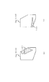
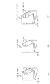
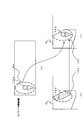
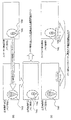
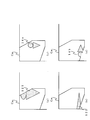
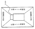
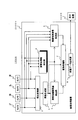
- FIG. 1 is an overall configuration diagram of an image processing system according to an embodiment of the present invention. It is the figure which looked at the vehicle based on embodiment of this invention from upper direction. It is a figure showing each bird's-eye view image based on embodiment of this invention. It is the figure which converted each bird's-eye view image on the coordinate of a perimeter bird's-eye view image based on embodiment of this invention. It is the figure which looked at the vehicle based on embodiment of this invention from diagonally left front. It is a figure explaining a part of all-around bird's-eye view image based on embodiment of this invention. It is a figure explaining a part of all-around bird's-eye view image based on embodiment of this invention.
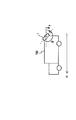
- a camera coordinate system XYZ a coordinate system X bu Y bu of the imaging surface of the camera, and a world coordinate system X w Y w Z w including a two-dimensional ground coordinate system X w Z w
- a figure showing a relationship It is a whole block diagram of the image processing system based on the other form of this invention.
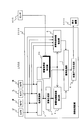
- FIG. 1 is an overall configuration diagram of an image processing system according to the present embodiment. An image processing apparatus, an image processing system using the same, and an image processing method used in the image processing system will be described with reference to FIG.
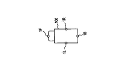
- the image processing system 1000 generates all-round bird's-eye view images from the cameras 1F, 1B, 1L, and 1R attached to the vehicle 100 and captured images obtained by these cameras, and displays the video data on the display device 3000. And an image processing device 2000 that outputs the image data of the all-around bird's-eye view image.
- the cameras 1F, 1B, 1L and 1R for example, a camera using a CCD (Charge Coupled Devices) or a camera using a CMOS (Complementary Metal Oxide Semiconductor) image sensor is used.
- CCD Charge Coupled Devices
- CMOS Complementary Metal Oxide Semiconductor
- FIG. 2 is a plan view of the camera 100 installed on the vehicle 100 as viewed from above.
- the vehicle 100 is illustrated as an example of a truck formed of a cab and a luggage compartment that is higher than the cab.
- the front part of the vehicle 100 for example, the upper part of the front mirror of the vehicle 100
- the rear part for example, the uppermost part of the rear part of the vehicle 100
- the left side part for example, the uppermost part of the left side surface of the vehicle 100
- right side part for example, the right side part.
- Cameras 1 ⁇ / b> F, 1 ⁇ / b> B, 1 ⁇ / b> L, and 1 ⁇ / b> R which are imaging devices, are attached to (for example, the uppermost portion of the right side surface of vehicle 100).
- the cameras 1F, 1B, 1L, and 1R may be referred to as a front camera, a rear camera, a left side camera, and a right side camera, respectively.
- the optical axis of the camera 1F is obliquely downward toward the front of the vehicle 100
- the optical axis of the camera 1B is obliquely downward to the rear of the vehicle 100
- the optical axis of the camera 1L is oblique to the left of the vehicle 100.
- Each camera is installed in the vehicle 100 so that the optical axis of the camera 1 ⁇ / b> R is obliquely downward to the right of the vehicle 100.
- the heights of the cameras 1L and 1R are assumed to be higher than the height of the camera 1F.
- the vehicle 100 shall be located on the ground.
- the image processing apparatus 2000 will be described.
- the image processing apparatus 2000 includes, for example, hardware formed from an integrated circuit that executes image processing in the present embodiment, and a CPU (central processing unit) that performs software processing of an image processing program that executes image processing in the present embodiment. And memory.
- the display device 3000 is formed from a liquid crystal display panel or the like. A display device included in a car navigation system or the like may be used as the display device 3000 in the image processing system.
- the viewpoint conversion unit 2 receives the captured image data from the cameras 1F, 1B, 1L, and 1R, and creates a bird's eye view image corresponding to each captured image data.
- the image synthesis unit 3 synthesizes the bird's-eye view images to generate an all-around bird's-eye view image.
- each bird's-eye view image and the all-around bird's-eye view image will be described in order to grasp the operations of the viewpoint conversion unit 2 and the image composition unit 3 regarding the all-around bird's-eye view creation method.
- a method for creating a bird's eye view image corresponding to each captured image data will be described last.
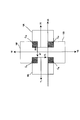
- bird's-eye view images 10F (coordinate systems X F Y F ), 10B (coordinate systems X B Y B ), 10L ( A coordinate system X L Y L ) and 10R (coordinate system X R Y R ) are shown.
- 10F, 10L, and 10R are converted into the bird's-eye view image 10B.
- FIG. 4 shows the bird's-eye view images 10F, 10B, 10L, and 10R represented on the all-around bird's-eye view and the coordinate system X B Y B.
- the all-around bird's-eye view is composed of at least two adjacent bird's-eye view images 10F, 10B, 10L, and 10R.
- the all-around bird's-eye view in FIG. Composed will be described using an example including all bird's-eye view images of the bird's-eye view images 10F, 10B, 10L, and 10R.
- the all-around bird's-eye view coordinates there is a portion where two adjacent bird's-eye view images overlap as shown in FIG.
- the hatched area to which C FL is attached is the portion where the bird's eye view images 10F and 10L overlap on the all-around bird's eye view coordinates.
- FIG. 5 is a view of the vehicle 100 as viewed obliquely from the left front.
- each camera generates a captured image obtained by capturing an image of a subject in its field of view (that is, an imaging space).
- the fields of view of the cameras 1F, 1B, 1L and 1R are represented by 12F, 12B, 12L and 12R, respectively. Note that only a part of the visual fields 12R and 12B is shown in FIG.
- the visual field 12F of the camera 1F includes an obstacle located within a predetermined range in front of the vehicle 100 and the ground in front of the vehicle 100 with respect to the installation position of the camera 1F. This predetermined range is determined from the angle of view of the camera.
- the visual field 12B of the camera 1B includes an obstacle positioned within a predetermined range behind the vehicle 100 and the ground behind the vehicle 100 with respect to the installation position of the camera 1B.
- the visual field 12L of the camera 1L includes an obstacle located within a predetermined range on the left side of the vehicle 100 with respect to the installation position of the camera 1L and the ground on the left side of the vehicle 100.
- the visual field 12R of the camera 1R includes an obstacle located within a predetermined range on the right side of the vehicle 100 and the ground on the right side of the vehicle 100 with respect to the installation position of the camera 1L.
- the obstacle is a three-dimensional object such as a person, in other words, an object having a height.
- the road surface that forms the ground is not an obstacle because it has no height.
- the cameras 1F and 1L commonly image a predetermined area in front of the vehicle 100 diagonally to the left. That is, the visual fields 12F and 12L intersect in a predetermined region diagonally to the left of the vehicle 100, and a common visual field exists.
- the common part common visual field of the visual field of each camera which is a space captured by each camera in common, is referred to as the above-described common imaging space.
- the visual fields 12F and 12R intersect with each other in a predetermined area on the right front side of the vehicle 100 to form a common imaging space
- the visual fields 12B and 12L intersect with each other in a predetermined area on the left rear side of the vehicle 100.
- These common imaging spaces are formed, and the visual fields 12B and 12R intersect with each other in a predetermined area obliquely rearward to the right of the vehicle 100 to form the common imaging space.
- the common imaging space 13 is shown using a bold line.
- the common imaging space 13 is a space that forms a cone whose bottom surface is the ground diagonally left front of the vehicle 100.
- an obstacle 14 such as a person is shown in the common imaging space 13.
- Overlapping portions of among a plurality of bird's-eye images, namely a C FL common imaging volume 13 is converted on the bird's eye view portion of the supra (hereinafter, referred to as overlapping portion).
- Bird's eye view images 10F image appears in the subject in a common imaging space 13 in the range of overlapping portion C FL viewed from the camera 1F (obstacle 14 such as in FIG. 5 (b)), the bird's-eye view image 10L, the overlap portion C
- An image of the subject in the common imaging space 13 viewed from the camera 1L appears in the FL range.
- the XF axis and the YF axis are coordinate axes of the coordinate system of the bird's eye view image 10F, and they are the above-described Xau axis and Yau axis.
- the XR axis and the YR axis are coordinate axes of the coordinate system of the bird's eye view image 10R, and they are the Xau axis and the Yau axis.
- the XL axis and the YL axis are coordinate axes of the coordinate system of the bird's eye view image 10L, and they are the X au axis and the Y au axis.
- the XB axis and the YB axis are coordinate axes of the coordinate system of the bird's eye view image 10B, and they are the X au axis and the Y au axis.
- each bird's eye view image is not necessarily rectangular.
- FIG. 6 shows an example in which each bird's-eye view image appears and the overlapping portion CFL is not rectangular.
- FIGS. 9A and 9B show bird's-eye view images 10L and 10F in all-around bird's-eye view coordinates, respectively.
- their overlapping portions C FL are indicated by hatched areas. ing.
- illustration of the image from the rear part of a vehicle is abbreviate
- the obstacle information extraction unit 4 extracts obstacle information related to the obstacle based on the bird's eye view image from the viewpoint conversion unit 2. For example, the bird's-eye view image data corresponding to each captured image data from the viewpoint conversion unit 2 is received, and each of the bird's-eye view images in the bird's-eye view image corresponding to the portion where the obstacle is imaged in the captured image is received. Obstacle information including position information related to the corresponding area, which is an area, is extracted and the obstacle information is output.
- the position information for example, the coordinates of the camera coordinate system XYZ, a coordinate of the coordinate system X bu Y bu of the imaging surface S, the coordinates of the two-dimensional ground surface coordinate system X w Z w, the world coordinate system X w Y w Z w coordinates Information such as coordinates of other coordinate systems is included.
- the obstacle information includes vertex information. Vertex information is the coordinates of vertices in a set of pixels (ie, an image) indicated by coordinate data. By knowing the coordinates of the vertices, it is possible to assume the figure by connecting the vertices with lines. Information such as the range, size, and area of the image can also be calculated. Hereinafter, it is assumed that the consideration of vertex information includes the assumption of information such as the range, size, and area of the image.
- the obstacle information extraction unit 4 is a target bird's-eye view image in an overlapping portion image that is commonly captured in a target bird's-eye view image that is a bird's-eye view image captured by a target imaging device including at least two cameras. Obstacles can be detected by performing difference processing between them, and the obstacle information is extracted using the results of the difference processing.
- the overlapping portion is not limited to a portion where two bird's-eye view images overlap as shown in FIG. 4, but is a portion where bird's-eye view images calculated from captured images of three or more imaging devices, that is, three or more bird's-eye view images overlap. Also good.
- the obstacle information extraction unit 4 receives the captured image data from the cameras 1F, 1B, 1L, and 1R, which are a plurality of imaging devices, and the obstacle in the area where the obstacle is captured from each of the captured images. Information may be extracted and obstacle information may be output.
- An image processing system 1000 in this case is shown in FIG. In this case, instead of the above-described difference processing between the bird's-eye view images, difference processing is performed between portions corresponding to the respective common imaging spaces of the captured image data from the cameras.
- the method of extracting the obstacle information by the obstacle information extracting unit 4 will be described later in the process of the overlapping part. In that case, description will be made on the assumption of the overlapping portion CFL and the like in FIG.
- the obstacle information extraction unit 4 does not extract the obstacle information and does not output the obstacle information. In the following, the description will be continued on the assumption that the obstacle information extracting unit 4 detects an obstacle unless otherwise specified.
- the captured image data from the cameras 1F, 1B, 1L, and 1R is received by the obstacle original image extraction unit 5, and based on the obstacle information extracted by the obstacle information extraction unit 4, the imaging including the obstacle is included.
- An obstacle original image which is an image including an obstacle (for example, an image including a part where the obstacle is imaged) is extracted from the image, and the information is output.
- the obstacle information extraction unit 4 does not extract the obstacle information and does not output the obstacle information to the obstacle original image extraction unit 5. Therefore, the obstacle original image extraction unit 5 does not extract the obstacle original image.
- the obstacle bird's-eye image detection unit 6 Based on the obstacle information extracted by the obstacle information extraction unit 4, the obstacle bird's-eye image detection unit 6 obtains an obstacle bird's-eye image corresponding to the obstacle in the synthetic bird's-eye view image from the all-around bird's-eye view image. To detect. For example, a bird's-eye image obstacle region (an obstacle bird's-eye image) corresponding to the corresponding region in the synthesized bird's-eye view image is detected, and information related thereto is output. When no obstacle is detected by the obstacle information extraction unit 4, the obstacle information extraction unit 4 does not extract the obstacle information and does not output the obstacle information to the obstacle bird's-eye image detection unit 6. Therefore, the obstacle bird's-eye image detection unit 6 does not detect the obstacle bird's-eye image.
- a bird's-eye image obstacle region an obstacle bird's-eye image corresponding to the corresponding region in the synthesized bird's-eye view image
- the replacement processing unit 7 extracts the obstacle bird's-eye image detected by the obstacle bird's-eye image detection unit 6 by the obstacle original image extraction unit 5 based on the information about the bird's-eye image obstacle region from the obstacle bird's-eye image detection unit 6.
- the image replaced with the obstacle original image is output as a replacement synthesized bird's-eye view image.
- replacement is performed using the obstacle original image extracted by the obstacle original image extraction unit 5 instead of the image including the obstacle bird's-eye image detected by the obstacle bird's-eye image detection unit 6.
- a new all-round bird's-eye view image (hereinafter referred to as a replacement combined bird's-eye view image) is generated and output.
- the obstacle original image extraction unit 5 does not extract the obstacle original image, but sends the information of the obstacle original image to the replacement processing unit 7. Since the obstacle bird's-eye image detection unit 6 does not output the obstacle bird's-eye image and does not output the information of the bird's-eye image obstacle region to the replacement processing unit 7, the replacement processing unit 7 does not output the information. Without generating an image, the all-around bird's-eye view image from the image composition unit 3 is output as it is.
- the video data generation unit 8 generates video data for causing the display device 9 to display the all-around bird's-eye view image or the replacement synthesized bird's-eye view image output from the replacement processing unit. That is, the data is converted into a data structure or pixel information that matches the display format or display standard of the display device 9 and output.
- the obstacle 14 when the obstacle 14 exists in the common imaging space 13 where the imaging area of the camera 1F and the imaging area of the camera 1L overlap, the obstacle is detected by the camera 1F.
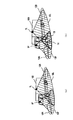
- a bird's-eye view image is generated from an image obtained by capturing 14, as shown in FIG. 7B, an image 122 in which the obstacle 14 falls in the left direction of the vehicle in the overlapping portion C FL of the all-around bird's-eye view image. Converted.
- the obstacle 14 at the overlapping portion C FL all-round bird's eye view image collapse in front of the vehicle The image 121 is converted.
- the image 122 is not only tilted leftward but also distorted and / or extended in the imaging direction depth direction. It is converted not only to fall forward but also to be distorted and / or extended in the imaging direction depth direction, which is schematically shown in the figure.
- the obstacle bird's-eye view image is not limited to the whole image as shown in the figure, and corresponds to the obstacle bird's-eye image even if only a part is shown. This is because even a partial image is later replaced with an obstacle original image, so there is no problem even if the image before replacement is partial.
- a difference calculation from 111 (see FIG. 11A) is performed.
- the information of the overlapping portion is obtained from the rotation angle when the coordinate conversion is performed when creating FIG. 4, the translational mobility, the vertex coordinates of the regions 10F, 10L, 10R, and 10B.
- part of the area 121a of the portion 111 corresponding to the overlapping portion C FL in bird's-eye view according to the captured image of the camera 1L is a portion corresponding to the image 122.
- part of the region 122a of the portion 112 corresponding to the overlapping portion C FL in bird's-eye view according to the captured image of the camera 1F is a portion corresponding to the image 121.
- the part excluding the image 121 and the area 121a of the part 111 and the part excluding the image 122 and the area 122a of the part 112 are bird's-eye view conversion images of the image of the ground.
- the part 123 for example, a region whose difference value is not 0 is extracted.
- pixel values luminance and color difference, red green blue value, etc.
- An arithmetic method for setting to zero is used.
- the part 123 By extracting the part 123, it can be detected that an obstacle exists in the common imaging space 13, and the coordinates of the part 123 in the coordinate system X B Y B (all-around bird's-eye view image) shown in FIG. And the range thereof are obstacle information such as position information in the coordinate system X B Y B included in the obstacle information and vertex information.
- the obstacle information includes positional information, vertex information, and the like in the captured image (specifically, in the case of the portion 123, the visual field 12F and the visual field 12L including the obstacle) in order to extract the obstacle original image. It is.
- the obstacle information is mainly used by the coordinate system X B Y B used in the obstacle bird's-eye image detection unit 6, that is, the coordinates in the bird's-eye view image, and mainly in the obstacle original image extraction unit 5.
- the coordinates in the visual field 12F and the visual field 12L, that is, the coordinates in the captured image are included, and are output from the obstacle information extraction unit 4.
- the coordinates in the captured image are calculated from the coordinates in the bird's-eye view image, but since the bird's-eye view image is originally obtained by converting from the captured image, all the coordinates of the obstacle in the captured image are calculated from all the coordinates of the obstacle in the bird's-eye view. It can be easily understood that it can be calculated.
- the image 121 and the image 122 are two-dimensional obstacle images.
- the shape of the portion 123 is a V-shape formed of the image 121 and the image 122 as shown in FIG. 8C
- the image 121 and the image 122 are two-dimensional obstacle images captured. It can be.
- Obstacle information can be obtained, for example, by storing the direction, position, vertex information, and the like of the portion 123 as table information in the image processing apparatus 2000. In the following description, the obstacle information is described as an example of coordinates as position information.
- (A) in the figure is an image taken by the camera 1F.
- the obstacle 14 is imaged at the left end of the image.
- the area 14a is an area where the obstacle 14 extracted by the obstacle original image extraction unit 5 is imaged, and is the obstacle 14 shown in the captured image.
- a region 14b in an image captured by the camera 1L, which will be described later, is a region in which the obstacle 14 extracted by the obstacle original image extraction unit 5 is imaged, and is an obstacle 14 imaged in the captured image. is there.
- the image 14c is an image (an obstacle original image) including a region 14a where an obstacle is imaged.
- the range of the image 14c is arbitrary as long as it includes the image 14a.
- a circumscribed ellipse or a circumscribed rectangle of the image 14a, the entire overlapping portion CFL , or a shape obtained by enlarging the image 14a by 50% can be taken.
- a circumscribed ellipse is described as an example.
- the obstacle original image extraction unit 5 uses the position information included in the obstacle information (specifically, all coordinates included in the image 14a) to determine the length in the long direction of the region 14a and the length in the short direction perpendicular thereto.
- the ellipse is calculated and the major and minor lengths in the major and minor directions are calculated.
- the ellipse of the image 14d is obtained by calculating an ellipse obtained by enlarging the ellipse about 2 to 3 times in the major axis direction and about twice in the minor axis direction.
- the reason why the enlargement width in the major axis direction is large is that the image 14c replaces the image 121, so the size of the image 14c must exceed the image 121, and the characteristics of conversion to a bird's eye view must be taken into account. It is.
- the captured image has a characteristic of being distorted and extended radially from the vertical direction of the captured image or from the center of the captured image.
- the characteristic that the captured image is distorted and stretched mainly depends on the height of the obstacle and the mounting height of the camera. If the height of the obstacle is relatively high and the mounting height of the camera is low, the distortion and elongation are large. .
- FIG. 9B is an enlarged view of the overlapping portion CFL portion of the bird's-eye view image of the captured image of FIG.
- the obstacle 14 is an image 121 that has been transformed as if it has fallen forward of the vehicle, or has been stretched and distorted unlike the actual vehicle.
- the image 14d is an image including an image 121 that is an area (the obstacle bird's-eye view image) in which the obstacle 14 detected by the obstacle bird's-eye image detection unit 6 is imaged.
- the range of the image 14d is arbitrary as long as it includes the image 121.
- the circumscribed ellipse or circumscribed rectangle of the image 121, the entire overlapping portion CFL , or a shape obtained by enlarging the image 121 by 10% can be taken.
- a circumscribed ellipse is described as an example.
- the obstacle bird's-eye image detection unit 6 uses the position information included in the obstacle information (specifically, all coordinates included in the image 121) to determine the length in the long direction of the image 121 and the length in the short direction perpendicular thereto.
- the ellipse is calculated and the major and minor lengths in the major and minor directions are calculated. Thereafter, an ellipse obtained by enlarging the ellipse by 10% with respect to the center is obtained to obtain the ellipse of the image 14d.
- 9C is an enlarged view of the overlapping portion C FL portion of the replacement synthesized bird's-eye view image generated by replacing the image 14c in place of the image 14d in the all-round bird's-eye view image by the replacement processing unit 7. .
- the shape, size, etc. of the image 14c may be any shape, size, etc. including the image 14d. In the present embodiment, the case where the size of the image 14c is larger than the size of the image 14d will be described.
- the obstacle bird's-eye image detection unit 6 When the shape, size, etc. of the image 14c and the shape, size, etc. of the image 14d are matched, the obstacle bird's-eye image detection unit 6 to the obstacle original image extraction unit according to a data flow not shown in FIG.
- Information such as position information and vertex information of the image 14d may be sent to 5, or information such as position information and vertex information of the image 14c is sent from the obstacle original image extraction unit 5 to the obstacle bird's-eye view image detection unit 6. May be.
- the obstacle original image extraction unit 5 extracts the obstacle original image by using the obstacle information and / or information such as the position information and vertex information of the image 14d from the obstacle bird's-eye image detection unit 6.
- the obstacle bird's-eye image detection unit 6 detects the obstacle bird's-eye image using information such as obstacle information and / or position information of the image 14c from the obstacle original image extraction unit 5 and vertex information.
- a memory area A in which a bird's eye view of the entire circumference in the memory space is stored and a memory area B in which a captured image captured by the camera 1F is stored are depicted.
- An image 14d is stored in the memory area A
- an image 14c is stored in the memory area B.
- the image data stored in the memory is schematically drawn on the memory area. This figure also shows a case where the shape and size of the image 14c match the shape and size of the image 14d.
- the image 14c is read from the memory area B (read), and the image 14c is written to the memory area A so as to fill the image 14d in the memory area A (write). Thereafter, by reading out the all-around bird's-eye view image generated from the memory area A, the replacement synthesized bird's-eye view image can be output.
- the all-round bird's-eye view image other than the image 14d is read from the memory area A, and the image 14c is read from the memory area B.
- the replacement composite bird's-eye view image can be output.
- the storage destination address of the image 14c and the storage destination address of the image 14d include at least position information of the area where the obstacle is imaged in the obstacle information output from the obstacle information extraction unit 4. It is calculated with reference to the obstacle information.
- Which block the image 14c and the image 14d are included in is determined from obstacle information such as position information (ie, image coordinates) in the coordinate system X B Y B , vertex information (ie, an area included in the image), and the like.
- the storage destination address can be determined. Without being limited to this example, if each pixel is given an address with a certain regularity, it is easy to calculate which address is the pixel constituting the image 14c or 14d from obstacle information such as coordinates. I can do things.
- the replacement processing unit 7 may perform the above-described processing of the obstacle original image extraction unit 5 by the replacement processing unit 7 performing the above address calculation and reading from the memory. That is, the circumscribed ellipse of the image 14c is calculated by a replacement process including the function of the obstacle original image extraction unit 5 by the inverse operation of the expression (7) based on the coordinate information in the captured image in the obstacle information and the information on the image 14d. This is done in part 7.
- the replacement processing unit 7 detects the obstacle from the captured image by the camera based on the information related to the obstacle bird's-eye image detected by the obstacle bird's-eye image detection unit 6. An original image is extracted, and an image obtained by replacing the obstacle bird's-eye image detected by the obstacle bird's-eye image detection unit 6 with the obstacle original image can be output as a replacement synthesized bird's-eye view image.
- the replacement processing unit 7 can extract the obstacle original image from the captured image like the obstacle original image extracting unit 5, and replace the obstacle bird's-eye view image with the obstacle. It can be replaced using the original image. [Visibility in Examples] Next, the point that the visibility is improved in the replacement synthesized bird's-eye view image will be described with reference to FIG. 9.
- the image is like a fallen image like the image 121 or the image 122, and in addition, as if it extends in the imaging direction depth direction, And / or it is often seen that it is transformed in a distorted manner.
- the replacement composite bird's-eye view image using the obstacle image extracted from the image captured by each camera without using the obstacle image converted into the bird's-eye view image as in the present embodiment for the driver.
- An image of an obstacle without a sense of incongruity is displayed on the display device 3000, and the visibility of the driver who has seen the obstacle 14 is improved.
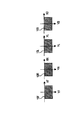
- Figure 11 shows what has been the expansion of the overlap portion C FL displayed on the display unit of the display device 3000.
- (c) or (d) of the figure compared with the image 121 or image 122 converted into a bird's eye view as shown in (a) or (b) of the figure.
- the obstacle image before being converted into a bird's eye view imaged by a simple camera was used, it can be said that the visibility is improved in (14a, 14b).
- which of (c) and (d) is used is determined by an arbitrary method from the viewpoint of visibility.
- the figure (c) may be selected from the point that the obstacle is completely displayed. Whether or not the image is completely displayed can be determined from the degree of overlap with the boundary of the overlap portion CFL .
- the present invention is not limited to this, and even if the same figure (c) is not completely displayed and is a partial case, the obstacle is viewed in a larger degree, that is, the entire obstacle is displayed. The one closer to the image may be selected.
- FIG. 12 shows an example of the all-around bird's-eye view image displayed on the display device 3000 which is a liquid crystal display panel or the like included in a car navigation system or the like.
- a picture corresponding to the vehicle 100 is displayed in the center, and video data generation units are respectively provided in portions corresponding to the front, rear, left and right sides of the vehicle (that is, the upper, lower left and right portions of the vehicle on the display screen, respectively).
- 8 is displayed according to the video data of the bird's eye view image obtained from the cameras 1F, 1B, 1L and 1R.
- the image processing apparatus 2000 that improves the visibility in the synthetic bird's-eye view image, the image processing method using the image processing apparatus 2000, and the image processing system 1000.
- the overall configuration of this embodiment is shown in FIG. 1 as in the first embodiment described above, but the configuration or operation of the obstacle information extraction unit 4 in the same drawing is different from that of the first embodiment. In the figure, since the configuration other than the obstacle information extraction unit 4 is the same as that of the first embodiment, the description thereof is omitted.
- the obstacle information extraction unit 4 detects an obstacle using an optical flow technique, and extracts obstacle information using the detection result obtained by the optical flow technique. To do. That is, it is possible to detect an obstacle without using a common imaging space of the imaging spaces of the two cameras or an overlapping portion where it is converted on the bird's eye view. Therefore, the application range of the method of the present embodiment is not limited to the overlapping portion. Further, no separate mechanism or parts for detecting an obstacle are required. It is assumed that each of the images captured by the plurality of cameras includes images that are temporally continuous.
- the optical flow method for example, in an image captured every time, a corresponding pixel group is specified, the amount of movement is calculated, and an imaging target is detected. Therefore, it is possible to detect from the amount of movement whether it is a part different from the background in the captured image or even an obstacle. For example, if there are two large amounts of movement, the larger object can be regarded as an imaging object in front, so that it can be regarded as an obstacle.
- Obstacle information can be extracted from the position of the different part, vertex information, and the like.
- the obstacle information can be obtained, for example, by providing the image processing apparatus 2000 with table information corresponding to the position of different parts, vertex information, and the like.
- the obstacle information extraction unit detects an obstacle using information from the sensor that detects the obstacle, and uses the information from the sensor.
- the obstacle information including at least position information of the area where the obstacle is imaged by the camera is extracted. That is, it is possible to detect an obstacle without using a common imaging space of the imaging spaces of the two cameras or an overlapping portion where it is converted on the bird's eye view. Therefore, the application range of the method of the present embodiment is not limited to the overlapping portion.
- FIG. 13 shows an overall configuration diagram of the image processing system according to the present embodiment.
- the difference from FIG. 1 is that a sensor 400 is added, and that the obstacle information extraction unit 4 uses the information from the sensor 400 to detect an obstacle and uses the information from the sensor to obtain obstacle information. It is the point which becomes the obstruction information extraction part 4a to extract.
- the obstacle information extraction unit 4a detects the position of the obstacle, vertex information, and the like based on the detection result of the sensor 400, and detects the presence of the obstacle in the common imaging space 13.
- the sensor 400 is an ultrasonic sensor
- the position of an object that reflects ultrasonic waves such as a sonar (SONAR: sound navigation ranging) used in a fish finder or an acoustic sounder using ultrasonic waves
- SONAR sound navigation ranging
- Obstacle information can be extracted from the position, vertex information, and the like based on the detection result.
- the obstacle information can be obtained, for example, by providing the image processing apparatus 2000 with table information corresponding to the position of different parts, vertex information, and the like.
- the image processing apparatus 2000 that improves the visibility in the composite bird's-eye view image, the image processing method using the image processing apparatus 2000, and the image processing system 1000.
- the present invention can also be applied to a bird's-eye view image that is a half circle around the vehicle or three-quarters around the vehicle. In the case of a bird's-eye view only in front of the vehicle, a single front camera is sufficient.
- the original image of the detected area is cut out using the optical flow and sensor information, and an image obtained by replacing the obstacle bird's-eye view image with the obstacle original image is output as a replacement composite bird's-eye view image. can do. Thereby, a bird's eye view image with high visibility can be displayed.
- the image processing apparatus can be realized in hardware by a CPU, memory, or other LSI of an arbitrary computer.
- software it is realized by a program having a view support function loaded in a memory.
- 1 and 13 show functional blocks of a visual field support function realized by hardware and software.
- FIGS. 1 and 13 are expressed in terms of functional units, they tend to be understood in terms of hardware, but can be easily understood in terms of software by replacing the functional units with functional steps.
- each of images captured by a plurality of cameras 1 ⁇ / b> F, 1 ⁇ / b> B, 1 ⁇ / b> L, 1 ⁇ / b> R is converted in a viewpoint conversion step through a viewpoint conversion step of converting a bird's-eye view image viewed from a virtual viewpoint.
- An object information extraction step is executed.
- an obstacle original image extraction step for extracting an obstacle original image from an image captured by the camera, and a synthetic bird's-eye view based on the obstacle information
- An obstacle bird's-eye image detection step for detecting an obstacle bird's-eye image from the image is executed, and instead of the image including the obstacle bird's-eye image detected in the obstacle bird's-eye image detection step in the synthesized bird's-eye view image, the obstacle A replacement composition bird's eye view image is output by executing a change composition step for replacement using the obstacle original image extracted in the original image extraction step.
- the replacement synthesized bird's-eye view image output from the change synthesis step generates video data to be displayed on the display device by executing the video data generation step.
- the image processing program Since the image processing program has the same effect as the image processing apparatus 2000 shown in FIG. 1, the image processing program that improves the visibility in the composite bird's-eye view image can be provided.
- Method for generating bird's-eye view image First, a method for generating a bird's eye view image from a captured image captured by one camera will be described. The generation of the bird's eye view image is performed by the viewpoint conversion unit 2. In the following description, the ground is assumed to be on a horizontal plane, and “height” represents the height with respect to the ground.
- the vehicle 100 is, for example, a truck.
- the vehicle 100 is illustrated as an example of a truck formed of a cab and a luggage compartment that is higher than the cab.
- the angle ⁇ 2 is generally called a look-down angle or a depression angle.
- FIG. 15 shows the relationship between the camera coordinate system XYZ, the coordinate system X bu Y bu of the imaging surface S of the camera 1, and the world coordinate system X w Y w Z w including the two-dimensional ground coordinate system X w Z w. ing.
- the camera coordinate system XYZ is a three-dimensional coordinate system as shown in the figure with the X axis, the Y axis, and the Z axis orthogonal to each other as coordinate axes.
- the coordinate system X bu Y bu is a two-dimensional coordinate system represented in the figure with the X bu axis and the Y bu axis orthogonal to each other as coordinate axes.
- the two-dimensional ground coordinate system X w Z w is a two-dimensional coordinate system represented in the figure with the X w axis and the Z w axis orthogonal to each other as coordinate axes.
- World coordinate system X w Y w Z w is, X w axis and Z w axes, a three-dimensional coordinate system with the coordinate axes 3 axes Y w axis perpendicular to these two axes.
- the camera coordinate system XYZ In the camera coordinate system XYZ, with the optical center of the camera 1 as the origin O, the Z axis in the optical axis direction, the X axis in the direction perpendicular to the Z axis and parallel to the ground, and the direction perpendicular to the Z axis and the X axis
- the Y axis is taken.
- X bu Y bu of the imaging surface S taking the origin at the center of the imaging surface S, X bu axis in the lateral direction of the imaging surface S, Y bu axes are taken in the longitudinal direction of the imaging surface S.
- X w Y w Z w In the world coordinate system X w Y w Z w, the intersection of the vertical line and the ground passing through the origin O of the camera coordinate system XYZ with the origin O w, Y w axis to the ground and perpendicular directions, X camera coordinate system XYZ X w axis in the axial direction parallel, Z w axis is taken in a direction orthogonal to the X w axis and Y w axis.
- the Xw axis is at a position translated from the X axis, the direction of movement is the vertical line direction, and the amount of translation is h.
- the coordinates in the camera coordinate system XYZ are expressed as (x, y, z).
- x, y, and z are an X-axis component, a Y-axis component, and a Z-axis component, respectively, in the camera coordinate system XYZ.
- the coordinates in the world coordinate system X w Y w Z w are expressed as (x w , y w , z w ).
- x w , y w, and z w are an X w axis component, a Y w axis component, and a Z w axis component in the world coordinate system X w Y w Z w , respectively.
- the coordinates in the two-dimensional ground coordinate system X w Z w are expressed as (x w , z w ).
- x w and z w are, respectively, in the two-dimensional ground surface coordinate system X w Z w, a X W-axis component and Z W-axis component, they X W axis component and in the world coordinate system based X w Y w Z w It matches the Z W axis component.
- the coordinates of the imaging surface S in the coordinate system X bu Y bu are expressed as (x bu , y bu ).
- x bu and y bu are an X bu axis component and a Y bu axis component in the coordinate system X bu Y bu of the imaging surface S, respectively.
- a conversion formula between the coordinates (x, y, z) of the camera coordinate system XYZ and the coordinates (x w , y w , z w ) of the world coordinate system X w Y w Z w is expressed by the following formula (1). Is done.
- a bird's eye view coordinate system X au Y au that is a coordinate system for the bird's eye view image is defined.
- the bird's eye view coordinate system X au Y au is a two-dimensional coordinate system having the X au axis and the Y au axis as coordinate axes.
- the coordinates in the bird's eye view coordinate system X au Y au are expressed as (x au , y au ).
- the bird's-eye view image is represented by pixel signals of a plurality of pixels arranged two-dimensionally, and the position of each pixel on the bird's-eye view image is represented by coordinates (x au , y au ).
- x au and y au are an X au axis component and a Y au axis component in the bird's eye view coordinate system X au Y au , respectively.
- the bird's-eye view image is obtained by converting an image captured by an actual camera into an image viewed from the viewpoint of a virtual camera (hereinafter referred to as a virtual camera) existing at the position of the virtual viewpoint. More specifically, it is assumed that the virtual camera is located above the ground and the imaging direction is vertically downward, and the bird's-eye view image is converted into an image in which the actual captured image of the camera looks down on the ground surface in the vertical direction. Is.
- the conversion of the viewpoint when generating the bird's-eye view image from the captured image is generally called viewpoint conversion.
- Projection from the two-dimensional ground coordinate system X w Z w to the bird's eye view coordinate system X au Y au of the virtual camera is performed by parallel projection.
- the height of the virtual camera i.e., the height of the virtual viewpoint
- the two-dimensional ground surface coordinate system X w Z w of the coordinate (x w, z w) and bird's eye view coordinate system X au Y au coordinates (x au , Y au ) is expressed by the following equation (4).
- the height H of the virtual camera is set in advance. Furthermore, the following formula (5) is obtained by modifying the formula (4).
- the captured image of the camera 1 is converted into a bird's eye view image by using the above equation (7). Converted.
- image processing such as lens distortion correction is appropriately performed on the captured image of the camera 1, and the captured image after the image processing is converted into a bird's eye view image using the above equation (7).
- the present invention can be applied to the field of image processing.
Landscapes
- Engineering & Computer Science (AREA)
- Multimedia (AREA)
- Theoretical Computer Science (AREA)
- Physics & Mathematics (AREA)
- Mechanical Engineering (AREA)
- Computing Systems (AREA)
- Geometry (AREA)
- Computer Graphics (AREA)
- General Physics & Mathematics (AREA)
- Closed-Circuit Television Systems (AREA)
- Image Processing (AREA)
- Image Analysis (AREA)
Abstract
複数の撮像画像の夫々を鳥瞰図画像に変換し、変換された各鳥瞰図画像を合成して合成鳥瞰図画像を生成し、前記鳥瞰図画像に基づいて障害物に関する障害物情報を抽出し、抽出された前記障害物情報に基づいて、前記撮像装置によって撮像された画像から、前記障害物を含む画像である障害物原画像を抽出し、抽出された前記障害物情報に基づいて、前記合成鳥瞰図画像から、前記合成鳥瞰図画像の中の前記障害物に対応する障害物鳥瞰画像を検出し、前記障害物鳥瞰画像検出部で検出された前記障害物鳥瞰画像を前記障害物原画像抽出部で抽出された前記障害物原画像に置換した画像を置換合成鳥瞰図画像として出力させ、出力された前記置換合成鳥瞰図画像を表示装置に表示させるための映像データを生成する。これにより、合成鳥瞰図画像における視認性が向上する。
Description
本発明は、画像処理システム及び画像処理方法に関し、また画像処理システムに用いられる画像処理装置および画像処理プログラムに関する。特に、車両に設置された複数のカメラの撮像画像から鳥瞰図画像を生成し、それら各鳥瞰図画像を合成する技術に関する。
自動車などの車両の運転者に対して運転時における死角箇所の視界情報を提供する事が考えられてきている。バックするときには車両の後方などに死角が生じるため、運転者にとって後方確認が難しくなる。そこで、死角となりやすい車両の後方を監視する撮像装置たる車載式のカメラ(以下、単にカメラと称す)を車に装備して、その撮像画像をカーナビゲーション装置等の画面に表示するシステムが開発されてきている。
また、カメラが撮像した映像を単に表示するのではなく、画像処理技術を使用して、人間にとって見て理解するのにより無理のない映像を見せるための研究がなされている。その一つに、撮像した映像を幾何学的変換すなわち座標変換を行うことにより、地面の上方などの仮想視点から見たようないわゆる鳥瞰図と呼ばれる画像を生成して表示する技術がある。この鳥瞰図画像を画面に表示することによって、運転者は鳥瞰図画像を見て死角たる車両後方の状況を詳しくかつより無理なく把握することができる。
更に、複数のカメラから得られた画像を上で述べたように座標変換することで得られる各鳥瞰図画像を合成して車両全周の状況を上方から見た映像である合成鳥瞰図画像(以下、全周鳥瞰図画像とも称する)を作成し、この全周鳥瞰図画像を画面に表示させる画像処理システムが開発されている。この画像処理システムでは、車両全周の状況を上方から見た映像として運転者に提示することができるため、車両の周辺を360度死角なくしかも見てより無理なく把握できるという長所がある。ここでいう合成とは、その鳥瞰画像同士が整合性がとれるように、隣り合う各鳥瞰図画像同士を互いに移動、回転させて、隣り合わせて貼り合わせて一つの鳥瞰図とすることを言う。なお、整合性よく隣り合わせる際には各鳥瞰図間に重なる部分が発生する。
特許文献1に、複数の俯瞰画像(鳥瞰画像のこと)を使用し、それらを合成した俯瞰画像を表示する車両周辺監視装置が記載されている。
特開2007- 27948号公報
しかしながら特許文献1に記載の技術によると、鳥瞰図においては撮像された立体的な障害物があたかも地面に平面的に倒れていたものであったかのように見えたりさらにはその障害物の形状が実際とは異なる歪んだ形状であるかのように感じられたりするので、車両を運転する運転者にとって、合成された鳥瞰図を見た際に障害物が何であるかを把握するのに無理あるものとなる場合が多い。当該障害物は進行上の障害物である場合が多いので、運転者に対して違和感無く把握されるべき物である。
そこで本発明は、上述のように鳥瞰図画像を合成して合成鳥瞰図画像が得られる際に、障害物が合成鳥瞰図画像において表示される際に運転者にとって違和感のある表示となってしまうといった視認性に関する問題を鑑み、合成鳥瞰図画像における視認性を向上させる“画像処理装置”および“画像処理プログラム”を提供することを目的とする。また、それらを用いた“画像処理システム”及び“画像処理方法”を提供することを目的とする。
本発明に係る画像処理装置は、複数台の撮像装置によって撮像された画像の夫々を、仮想視点から見た鳥瞰図画像に変換する視点変換部と、前記視点変換部で変換された各鳥瞰図画像を合成して合成鳥瞰図画像を生成する画像合成部とを備えた画像処理装置であって、前記鳥瞰図画像に基づいて障害物に関する障害物情報を抽出する障害物情報抽出部と、前記障害物情報抽出部で抽出された前記障害物情報に基づいて、前記撮像装置によって撮像された画像から、前記障害物を含む画像である障害物原画像を抽出する障害物原画像抽出部と、前記障害物情報抽出部で抽出された前記障害物情報に基づいて、前記合成鳥瞰図画像から、前記合成鳥瞰図画像の中の前記障害物に対応する障害物鳥瞰画像を検出する障害物鳥瞰画像検出部と、前記障害物鳥瞰画像検出部で検出された前記障害物鳥瞰画像を前記障害物原画像抽出部で抽出された前記障害物原画像に置換した画像を置換合成鳥瞰図画像として出力する置換処理部と、前記置換処理部から出力された前記置換合成鳥瞰図画像を表示装置に表示させるための映像データを生成する映像データ生成部とを備えている。
なお、前記障害物情報抽出部は、前記複数台の撮像装置のうちの少なくとも2台の撮像装置である対象撮像装置によって撮像されている前記鳥瞰図画像である対象鳥瞰図画像の重なり合う領域の画像において、前記対象鳥瞰図画像間で差分処理を行うことで前記障害物情報を抽出してよい。
本発明に係る画像処理装置は、複数台の撮像装置によって撮像された画像の夫々を、仮想視点から見た鳥瞰図画像に変換する視点変換部と、前記視点変換部で変換された各鳥瞰図画像を合成して合成鳥瞰図画像を生成する画像合成部とを備えた画像処理装置であって、前記鳥瞰図画像に基づいて障害物に関する障害物情報を抽出する障害物情報抽出部と、前記障害物情報抽出部で抽出された前記障害物情報に基づいて、前記合成鳥瞰図画像から、前記合成鳥瞰図画像の中の前記障害物に対応する障害物鳥瞰画像を検出する障害物鳥瞰画像検出部と、前記障害物鳥瞰画像検出部で検出された前記障害物鳥瞰画像に関する情報に基づいて、前記撮像装置によって撮像された画像から、前記障害物を含む画像である障害物原画像を抽出し、前記障害物鳥瞰画像検出部で検出された前記障害物鳥瞰画像を前記障害物原画像に置換した画像を置換合成鳥瞰図画像として出力する置換処理部と、前記置換処理部から出力された前記置換合成鳥瞰図画像を表示装置に表示させるための映像データを生成する映像データ生成部とを備えている。
本発明に係る画像処理プログラムは、複数台の撮像装置によって撮像された画像の夫々を、仮想視点から見た鳥瞰図画像に変換する視点変換ステップと、前記視点変換ステップで変換された各鳥瞰図画像を合成して合成鳥瞰図画像を生成する画像合成ステップとを含む、コンピュータを画像処理装置として動作させる画像処理プログラムであって、前記鳥瞰図画像に基づいて障害物に関する障害物情報を抽出する障害物情報抽出ステップと、前記障害物情報抽出ステップで抽出された前記障害物情報に基づいて、前記撮像装置によって撮像された画像から、前記障害物を含む画像である障害物原画像を抽出する障害物原画像抽出ステップと、前記障害物情報抽出ステップで抽出された前記障害物情報に基づいて、前記合成鳥瞰図画像から、前記合成鳥瞰図画像の中の前記障害物に対応する障害物鳥瞰画像を検出する障害物鳥瞰画像検出ステップと、前記障害物鳥瞰画像検出部で検出された前記障害物鳥瞰画像を前記障害物原画像抽出部で抽出された前記障害物原画像に置換した画像を置換合成鳥瞰図画像として出力する置換処理ステップと、前記置換処理ステップから出力された前記置換合成鳥瞰図画像を表示装置に表示させるための映像データを生成する映像データ生成ステップとを含む。
本発明に係る画像処理システムは、上に記載の画像処理装置と、前記複数台の撮像装置、及び、前記表示装置を備えている。
本発明に係る画像処理方法は、複数台の撮像装置によって撮像された画像の夫々を、仮想視点から見た鳥瞰図画像に変換し、変換された各鳥瞰図画像を合成して合成鳥瞰図画像を生成する画像処理方法であって、前記鳥瞰図画像に基づいて障害物に関する障害物情報を抽出し、抽出された前記障害物情報に基づいて、前記撮像装置によって撮像された画像から、前記障害物を含む画像である障害物原画像を抽出し、抽出された前記障害物情報に基づいて、前記合成鳥瞰図画像から、前記合成鳥瞰図画像の中の前記障害物に対応する障害物鳥瞰画像を検出し、前記障害物鳥瞰画像検出部で検出された前記障害物鳥瞰画像を前記障害物原画像抽出部で抽出された前記障害物原画像に置換した画像を置換合成鳥瞰図画像として出力させ、出力された前記置換合成鳥瞰図画像を表示装置に表示させるための映像データを生成する。
撮像装置は、静止画像を撮像するカメラや動画像を撮像するカメラなどが該当する。
障害物とは、路面上や地上などに描かれた平面的な文字や図形等では無く、それら路面上や地上などに存在する立体的な物体のことを表す。従って、障害物としては、例えば、人や植物や動物などの生き物や、車や自動二輪や自転車などの車両、標識や柵やポストなどの人工物が当てはまる。
なお、画像とは、撮像された被写体の姿が可視化された像の意味に限定されるものではなく、本発明においては、視点変換や置換などの画像処理の対象となる画像のデータを含むものと解釈されるものである。
障害物鳥瞰画像は、障害物が写っていれば、全体の画像だけに限られず、部分的な画像であってもよい。
なお、前記複数台の撮像装置によって撮像された画像の夫々が時間的に連続している画像を含んでいる場合に、前記障害物情報抽出部は、オプティカルフローの手法により前記障害物情報を抽出してもよい。
また本発明の画像処理装置は、1台の撮像装置によって撮像された時間的に連続している画像の夫々を、仮想視点から見た鳥瞰図画像に変換する視点変換部を備えた画像処理装置であって、オプティカルフローの手法により前記障害物が前記撮像装置によって撮像されている領域の障害物情報を抽出する障害物情報抽出部と、前記障害物情報抽出部で抽出された前記障害物情報に基づいて、前記撮像装置によって撮像された画像から、前記障害物を含む画像である障害物原画像を抽出する障害物原画像抽出部と、前記障害物情報抽出部で抽出された前記障害物情報に基づいて、前記鳥瞰図画像から、前記鳥瞰図画像の中の前記障害物に対応する障害物鳥瞰画像を検出する障害物鳥瞰画像検出部と、前記障害物鳥瞰画像検出部で検出された前記障害物鳥瞰画像を前記障害物原画像抽出部で抽出された前記障害物原画像に置換した画像を置換鳥瞰図画像として出力する置換処理部と、前記置換処理部から出力された前記置換鳥瞰図画像を表示装置に表示させるための映像データを生成する映像データ生成部とを備えていてもよい。
また本発明の画像処理装置は、複数台の撮像装置によって撮像された画像の夫々を、仮想視点から見た鳥瞰図画像に変換する視点変換部と、前記視点変換部で変換された各鳥瞰図画像を合成して合成鳥瞰図画像を生成する画像合成部とを備えた画像処理装置であって、障害物を検出するセンサからの情報を使用して、前記障害物が前記撮像装置によって撮像されている領域の障害物情報を抽出する障害物情報抽出部と、前記障害物情報抽出部で抽出された前記障害物情報に基づいて、前記撮像装置によって撮像された画像から、前記障害物を含む画像である障害物原画像を抽出する障害物原画像抽出部と、前記障害物情報抽出部で抽出された前記障害物情報に基づいて、前記合成鳥瞰図画像から、前記合成鳥瞰図画像の中の前記障害物に対応する障害物鳥瞰画像を検出する障害物鳥瞰画像検出部と、前記障害物鳥瞰画像検出部で検出された前記障害物鳥瞰画像を前記障害物原画像抽出部で抽出された前記障害物原画像に置換した画像を置換合成鳥瞰図画像として出力する置換処理部と、前記置換処理部から出力された前記置換合成鳥瞰図画像を表示装置に表示させるための映像データを生成する映像データ生成部とを備えていてもよい。
また本発明の画像処理装置は、1台の撮像装置によって撮像された時間的に連続している画像の夫々を、仮想視点から見た鳥瞰図画像に変換する視点変換部を備えた画像処理装置であって、障害物を検出するセンサからの情報を使用して、前記障害物が前記撮像装置によって撮像されている領域の障害物情報を抽出する障害物情報抽出部と、前記障害物情報抽出部で抽出された前記障害物情報に基づいて、前記撮像装置によって撮像された画像から、前記障害物を含む画像である障害物原画像を抽出する障害物原画像抽出部と、前記障害物情報抽出部で抽出された前記障害物情報に基づいて、前記鳥瞰図画像から、前記鳥瞰図画像の中の前記障害物に対応する障害物鳥瞰画像を検出する障害物鳥瞰画像検出部と、前記障害物鳥瞰画像検出部で検出された前記障害物鳥瞰画像を前記障害物原画像抽出部で抽出された前記障害物原画像に置換した画像を置換鳥瞰図画像として出力する置換処理部と、前記置換処理部から出力された前記置換鳥瞰図画像を表示装置に表示させるための映像データを生成する映像データ生成部とを備えていてもよい。
前記障害物情報抽出部は、前記撮像装置によって撮像された画像の夫々から、障害物に関する障害物情報を抽出してもよい。
本発明によれば、合成鳥瞰図画像における視認性を向上させる“画像処理装置”および“画像処理プログラム”を提供することができる。また、それらを用いた“画像処理システム”及び“画像処理方法”を提供することができる。
本発明の意義ないし効果は、以下に示す実施の形態の説明により更に明らかとなろう。
ただし、以下の実施の形態は、あくまでも、本発明の一つの実施形態であって、本発明ないし各構成要件の用語の意義は、以下の実施の形態に記載されたものに制限されるものではない。
1、1F、1B、1L、1R カメラ
2 視点変換部
3 画像合成部
4、4a 障害物情報抽出部
5 障害物原画像抽出部
6 障害物鳥瞰画像検出部
7 置換処理部
8 映像データ生成部
1000 画像処理システム
2000 画像処理装置
3000 表示装置
10F、10B、10L、10R 鳥瞰図画像
12F、12B、12L、12R 視野
13 共通撮像空間
14 障害物
14a 障害物が撮像されている領域
14b 障害物が撮像されている領域
14c 障害物が撮像されている領域を含む画像
14d 障害物が鳥瞰図画像において撮像されている領域を含む画像
CFL 重なり部
100 車両
121、122 (鳥瞰変換)画像
123 差分領域
400 センサ
以下、本発明係る、画像処理装置および画像処理プログラム、およびそれらを用いた画像処理方法および、画像処理システムの実施の形態につき、図面を参照して具体的に説明する。参照される各図において、同一の部分には同一の符号を付し、同一の部分に関する重複する説明は省略する。
(第1の実施形態)
まず、全周鳥瞰図画像の作成方法について説明する。
[画像処理システムの構成と画像処理装置の動作]
図1に、本実施形態に係る画像処理システムの全体構成図を示す。同図を用いて、画像処理装置およびそれを用いた画像処理システムおよび画像処理システムで使用されている画像処理方法について説明する。本実施形態に係る画像処理システム1000は、車両100に取り付けられるカメラ1F、1B、1L及び1Rと、それら各カメラにて得られる撮像画像から全周鳥瞰図画像を生成しその映像データを表示装置3000へ出力する画像処理装置2000と、当該全周鳥瞰図画像の映像データを表示する表示装置3000と、を備える。
カメラ1F、1B、1L及び1Rとして、例えばCCD(Charge Coupled Devices)を用いたカメラや、CMOS(Complementary Metal Oxide Semiconductor)イメージセンサを用いたカメラが用いられる。
図2は、車両100へのカメラの設置状況を表し、車両100を上方から見た平面図である。同図では車両100は、運転室と運転室より高さのある荷室とから形成されるトラックを例として図示している。同図に示す如く、車両100の前部(例えば車両100のフロントミラー上部)、後部(例えば車両100の後部の最上部)、左側部(例えば車両100の左側面の最上部に)及び右側部(例えば車両100の右側面の最上部)に、夫々、撮像装置たるカメラ1F、1B、1L及び1Rが取り付けられている。なお、カメラ1F、1B、1L及び1Rは、夫々、前カメラ、後カメラ、左横カメラ及び右横カメラと呼ばれる場合がある。
カメラ1Fの光軸が車両100の前方斜め下向きになるように、且つ、カメラ1Bの光軸が車両100の後方斜め下向きになるように、且つ、カメラ1Lの光軸が車両100の左方斜め下向きになるように、且つ、カメラ1Rの光軸が車両100の右方斜め下向きになるように、各カメラは車両100に設置される。カメラ1L及び1Rの高さは、カメラ1Fの高さよりも高いものとする。また、車両100は、地面上に位置するものとする。
画像処理装置2000について述べる。
画像処理装置2000は、例えば本実施形態における画像処理を実行する集積回路から形成されるハードウエアや、本実施形態における画像処理を実行する画像処理プログラムのソフトウエア処理を行うCPU(中央処理装置)やメモリなどから成る。表示装置3000は、液晶ディスプレイパネル等から形成される。カーナビゲーションシステムなどに含まれる表示装置を、本画像処理システムにおける表示装置3000として流用しても良い。
画像処理装置2000において、カメラ1F、1B、1L及び1Rからの撮像画像データを視点変換部2が受けて、各撮像画像データに対応した鳥瞰図画像を作成する。画像合成部3は、各鳥瞰図画像を合成して全周鳥瞰図画像を生成する。
ここで、全周鳥瞰図作成方法に関する視点変換部2および画像合成部3の動作について把握するため、各鳥瞰図画像と全周鳥瞰図画像の関係について述べる。なお、各撮像画像データに対応した鳥瞰図画像の作成方法については最後で説明する。
図3に示す如く、カメラ1F、1B、1L及び1Rから得られる撮像画像から、夫々、作成された鳥瞰図画像10F(座標系XFYF)、10B(座標系XBYB)、10L(座標系XLYL)及び10R(座標系XRYR)が示されている。次に、カメラ1Bに対応する鳥瞰図画像10Bを基準として、他の3つの鳥瞰図画像10F、10L及び10Rを回転及び/又は平行移動することにより、それら(10F、10L及び10R)を鳥瞰図画像10Bにおける座標系XBYBに変換する。これにより、各鳥瞰図画像の座標が、全周鳥瞰図(本発明で言う合成鳥瞰図)画像における座標に変換される。以下、全周鳥瞰図画像における座標を、「全周鳥瞰図座標」とよぶ。
図4に、全周鳥瞰図と座標系XBYB上に表された鳥瞰図画像10F、10B、10L及び10Rを示す。全周鳥瞰図は、鳥瞰図画像10F、10B、10L及び10Rのうちの少なくとも隣り合う2つから構成されており、同図における全周鳥瞰図では鳥瞰図画像10F、10B、10L及び10Rの全ての鳥瞰図画像から構成される。なお、これ以後全周鳥瞰図は鳥瞰図画像10F、10B、10L及び10Rの全ての鳥瞰図画像からなる例で説明を行う。全周鳥瞰図座標には、同図に示す如く、2つの隣り合う鳥瞰図画像が重なり合う部分が存在する。同図において、CFLの符号が付された斜線領域が、全周鳥瞰図座標上において鳥瞰図画像10Fと10Lが重なり合う部分である。
当該重なり合う部分について説明する。
図5は、車両100を左斜め前方から見た図である。
同図には、各カメラの撮像空間が模式的に表されている。各カメラは、自身の視野(すなわち撮像空間)内の被写体を撮像した撮像画像を生成する。カメラ1F、1B、1L及び1Rの視野を、夫々、12F、12B、12L及び12Rにて表す。尚、視野12R及び12Bに関しては、同図において一部しか示されていない。
カメラ1Fの視野12Fには、カメラ1Fの設置位置を基準とした、車両100の前方の所定範囲内に位置する障害物及び車両100の前方の地面が含まれる。この所定範囲はカメラの画角から定まる。
カメラ1Bの視野12Bには、カメラ1Bの設置位置を基準とした、車両100の後方の所定範囲内に位置する障害物及び車両100の後方の地面が含まれる。
カメラ1Lの視野12Lには、カメラ1Lの設置位置を基準とした、車両100の左方の所定範囲内に位置する障害物及び車両100の左方の地面が含まれる。
カメラ1Rの視野12Rには、カメラ1Lの設置位置を基準とした、車両100の右方の所定範囲内に位置する障害物及び車両100の右方の地面が含まれる。
上記のように、各カメラの視点は異なり、すなわち各カメラの視野内に収まる被写体は異なる。なお、障害物とは、人物などの立体的な物体、言い換えると高さのある物体である。地面を形成する路面などは、高さがないため障害物ではない。
さて同図によるとカメラ1Fと1Lは、車両100の左斜め前方の所定領域を共通して撮像している。つまり、車両100の左斜め前方の所定領域にて視野12F及び12Lは交わり合って、共通の視野が存在する。この各カメラが共通して撮像した空間である各カメラの視野の共通部分共通視野を以下では、上述の共通撮像空間と呼ぶ。
同様に、車両100の右斜め前方の所定領域にて視野12Fと12Rは交わり合ってそれらの共通撮像空間が形成され、車両100の左斜め後方の所定領域にて視野12Bと12Lは交わり合ってそれらの共通撮像空間が形成され、車両100の右斜め後方の所定領域にて視野12Bと12Rは交わり合ってそれらの共通撮像空間が形成される。
以下では視野12Fと12Lとの間の共通撮像空間13に着目して説明を行う。共通撮像空間13以外の共通撮像空間に関しても同様の説明があてはまる。
図5(b)には、共通撮像空間13が太線を用いて示されている。共通撮像空間13は、車両100の左斜め前方の地面を底面とする錐体を形成するような空間となっている。同図には、この共通撮像空間13内に人などの障害物14が示されている。
複数の鳥瞰画像間の重なり合う部分、すなわち前出のCFLは共通撮像空間13が鳥瞰図上に変換された部分(以下、重なり部と呼ぶ)である。
鳥瞰図画像10Fの、重なり部CFLの範囲にはカメラ1Fから見た共通撮像空間13内の被写体(図5(b)の障害物14等)の画像が現れ、鳥瞰図画像10Lの、重なり部CFLの範囲にはカメラ1Lから見た共通撮像空間13内の被写体の画像が現れる。
重なり部に障害物がある場合の処理については後の重なり部における処理の所で述べる。重なり部はCFL以外に、鳥瞰図画像10Fと10Rが重なり合う重なり部CFRと、鳥瞰図画像10Bと10Lが重なり合う重なり部CBLと、鳥瞰図画像10Bと10Rが重なり合う重なり部CBRとがあるが、共通撮像空間13に対応する重なり部CFLに着目して説明を行う。
尚、図3及び図4において、XF軸及びYF軸は、鳥瞰図画像10Fの座標系の座標軸であり、それらは、前出のXau軸及びYau軸のことである。同様に、XR軸及びYR軸は、鳥瞰図画像10Rの座標系の座標軸であり、それらは、Xau軸及びYau軸のことである。同様に、XL軸及びYL軸は、鳥瞰図画像10Lの座標系の座標軸であり、それらは、Xau軸及びYau軸のことである。同様に、XB軸及びYB軸は、鳥瞰図画像10Bの座標系の座標軸であり、それらは、Xau軸及びYau軸のことである。
また、図3、4では、説明の上から、重なり部CFLを矩形で表記しているが、実際には重なり部CFLは矩形とはならない。また、各鳥瞰図画像も矩形になるとは限らない。図6に、各鳥瞰図画像が現れる領域及び重なり部CFLが矩形とならない場合の一例を示す。同図(a)及び(b)には、夫々、全周鳥瞰図座標における鳥瞰図画像10L及び10Fが表されており、同図(c)では、それらの重なり部CFLが斜線領域にて示されている。なお、同図(a)及び(c)において、車両の後部よりの画像の図示を省略している。
図1に戻って説明を続ける。図1の画像処理装置2000において、障害物情報抽出部4が視点変換部2からの鳥瞰図画像に基づいて障害物に関する障害物情報を抽出する。例えば、視点変換部2からの各撮像画像データに対応した鳥瞰図画像データを受けて、鳥瞰図画像の夫々から、撮像画像の中で障害物が撮像されている部分に対応する前記鳥瞰図画像の中の領域である対応領域に関する位置情報などを含む障害物情報を抽出し、障害物情報を出力する。
位置情報には、例えば、カメラ座標系XYZの座標、撮像面Sの座標系XbuYbuの座標、2次元地面座標系Xw Zwの座標、世界座標系Xw Yw Zwの座標などその他の座標系の座標といった情報が含まれる。他に障害物情報には、頂点情報が含まれる。頂点情報とは、座標データの示す画素の集合(すなわち画像)における頂点の座標などのことであり、当該頂点の座標が分かる事で、各頂点間を線でつないだ図形を想定することでその画像の範囲、大きさ、領域、といった情報も算出しうる。以後、頂点情報を考えることは、その画像の範囲、大きさ、領域、といった情報等を想定して考えることも含まれるとする。
本実施形態における障害物情報抽出部4は、少なくとも2台のカメラからなる対象撮像装置によって撮像されている鳥瞰図画像である対象鳥瞰図画像において共通して撮像されている重なり部の画像において対象鳥瞰図画像間で差分処理を行うことで障害物を検出でき、当該差分処理の結果を使用して前記障害物情報を抽出する。なお、重なり部は図4のような2枚の鳥瞰図画像が重なり合う部分に限られず3台以上の撮像装置の撮像画像から算出された鳥瞰図画像、すなわち3枚以上の鳥瞰図画像が重なり合う部分であってもよい。
なお、障害物情報抽出部4が複数の撮像装置たるカメラ1F、1B、1L及び1Rからの撮像画像データを受けて、撮像された画像の夫々から、障害物が撮像されている領域の障害物情報を抽出し、障害物情報を出力してもよい。この場合の画像処理システム1000を図16に示す。この場合、上記の鳥瞰図画像間での差分処理に代えて、各カメラからの撮像画像データの各々の共通撮像空間に相当する部分の間において差分処理を行う。
なお、障害物情報抽出部4での障害物情報の抽出の手法については後の重なり部における処理の所で説明する。その際、図4の重なり部CFL等を前提に説明する。
障害物情報抽出部4において障害物が検出されなかった場合は、障害物情報抽出部4は障害物情報を抽出せず当該障害物情報を出力しない。以下においては、特に断らない限り障害物情報抽出部4において障害物が検出された前提で説明を続ける。
カメラ1F、1B、1L及び1Rからの撮像画像データを障害物原画像抽出部5が受けて、障害物情報抽出部4で抽出された障害物情報に基づいて、障害物が含まれている撮像画像から、障害物を含む画像(例えば当該障害物が撮像されている部分を含む画像)である障害物原画像を抽出し、その情報を出力する。なお、障害物情報抽出部4において障害物が検出されなかった場合は、障害物情報抽出部4が障害物情報を抽出せず障害物原画像抽出部5に向けて当該障害物情報を出力しないので、障害物原画像抽出部5は障害物原画像の抽出を行わない。
障害物鳥瞰画像検出部6は、障害物情報抽出部4で抽出された障害物情報に基づいて、全周鳥瞰図画像から、前記合成鳥瞰図画像の中の前記障害物に対応する障害物鳥瞰画像を検出する。例えば、合成鳥瞰図画像の中の上記の対応領域に対応する鳥瞰画像障害物領域(障害物鳥瞰画像のこと)を検出し、それに関する情報を出力する。なお、障害物情報抽出部4において障害物が検出されなかった場合は、障害物情報抽出部4が障害物情報を抽出せず障害物鳥瞰画像検出部6に向けて当該障害物情報を出力しないので、障害物鳥瞰画像検出部6は障害物鳥瞰画像の検出を行わない。
置換処理部7は、障害物鳥瞰画像検出部6からの鳥瞰画像障害物領域に関する情報に基づき、障害物鳥瞰画像検出部6で検出された障害物鳥瞰画像を障害物原画像抽出部5で抽出された障害物原画像に置換した画像を置換合成鳥瞰図画像として出力する。例えば、全周鳥瞰図画像中において、障害物鳥瞰画像検出部6で検出された障害物鳥瞰画像を含む画像に代えて、障害物原画像抽出部5で抽出された障害物原画像を用いて置換し、合成させて新たな全周鳥瞰図画像(以下、置換合成鳥瞰図画像と称する)を生成し、出力する。なお、障害物情報抽出部4において障害物が検出されなかった場合は、障害物原画像抽出部5は障害物原画像の抽出を行わず置換処理部7に向けて障害物原画像の情報を出力しないので、また、障害物鳥瞰画像検出部6は障害物鳥瞰画像の検出を行わず置換処理部7に向けて鳥瞰画像障害物領域の情報を出力しないので、置換処理部7は置換合成鳥瞰図画像を生成せず、画像合成部3からの全周鳥瞰図画像をそのまま出力する。
置換処理部7の動作については、後で述べる。
映像データ生成部8では置換処理部から出力された、全周鳥瞰図画像または置換合成鳥瞰図画像を表示装置9に表示させるための映像データを生成する。すなわち、表示装置9の表示フォーマットや表示規格に合わせたデータ構造や画素情報に変換して出力する。
以上により、全周鳥瞰図画像において障害物が表示される際に運転者にとって違和感のある表示となってしまうといった視認性に関する問題が、置換合成鳥瞰図画像において解決することができ、視認性が向上した全周鳥瞰図画像となっている。この点については、後述する実施例における視認性の説明の所で明らかにする。
[重なり部における処理]
重なり部CFLにおけるカメラ1F、カメラ1Lにより撮像された各障害物画像にかかる処理と、障害物情報抽出部4において、差分処理の結果を使用して前記障害物情報を抽出する方法について説明する。
[重なり部における処理]
重なり部CFLにおけるカメラ1F、カメラ1Lにより撮像された各障害物画像にかかる処理と、障害物情報抽出部4において、差分処理の結果を使用して前記障害物情報を抽出する方法について説明する。
例えば、図5(b)に示されているように、カメラ1Fの撮像領域とカメラ1Lの撮像領域が重なり合う共通撮像空間13内に障害物14が存在している場合、カメラ1Fにて障害物14を撮像した画像から鳥瞰図画像を生成したとき、図7の(b)に示すように、全周鳥瞰図画像の重なり部CFLにおいて障害物14が車両の左方向に倒れた画像122となって変換される。一方、カメラ1Lにて障害物14を撮像した画像から鳥瞰図画像を生成した場合、同図(a)に示すように、全周鳥瞰図画像の重なり部CFLにおいて障害物14が車両の前方に倒れた画像121となって変換される。なお鳥瞰図画像に変換する場合によく見られるように、画像122は左方に倒れただけでなく歪んだ様に、および/または撮像方向奥行き方向に伸びた様に変換されており、画像121は前方に倒れただけでなく歪んだ様に、および/または撮像方向奥行き方向に伸びた様に変換されており、同図にはそのことが模式的に示されている。障害物鳥瞰画像は、同図のように全体が映っているものに限られず、一部だけが写っていても障害物鳥瞰画像に該当する。これは、部分的な画像であっても、後に障害物原画像で置換するのであるから、置換前の画像が部分的なものであっても問題はないからである。
障害物情報抽出部4では、カメラ1Fの撮像画像による鳥瞰図における重なり部CFLに相当する部分112(同図(b)参照)とカメラ1Lの撮像画像による鳥瞰図における重なり部CFLに相当する部分111(同図(a)参照)との差分演算を行う。なお当該重なり部の情報は、図4を作成する時に座標変換した際の回転の角度、平行移動の移動度、および領域10F、10L、10R、10Bの各頂点座標等から求まる。
図8を用いて更に述べる。同図(a)における部分111と同図(b)における部分112との間で差分演算を行う事により、同図(c)に示される部分123が抽出される。
同図(a)において、カメラ1Lの撮像画像による鳥瞰図における重なり部CFLに相当する部分111の領域121aの部分は画像122に対応する部分である。同図(b)において、カメラ1Fの撮像画像による鳥瞰図における重なり部CFLに相当する部分112の領域122aの部分は画像121に対応する部分である。通常、部分111の画像121と領域121aを除いた部分と、部分112の画像122と領域122aを除いた部分とは、地面を撮像したものの鳥瞰図変換画像であることから、略同じような画像に変換されるので、差分演算により同図(c)に示される画像121と画像122を併せた画像に対応する部分123が抽出される。当該部分123としては、例えばその差分値が0では無い領域が抽出される。なお差分演算では、対応する各画素間の画素値(輝度と色差や、赤緑青値など)を引き算し、その絶対値が所定の閾値と比較して零と見做せる場合にはその差を零とする演算方法などが使用される。
当該部分123が抽出された事で、共通撮像空間13に障害物が存在していることを検出でき、当該部分123の図4で示した座標系XBYB(全周鳥瞰図画像)における座標やその範囲等が、障害物情報に含まれる座標系XBYBにおける位置情報、や頂点情報等の障害物情報となる。なお障害物情報には、障害物原画像を抽出するために、撮像画像(部分123の場合は、具体的には当該障害物を含む視野12Fと視野12L)における位置情報や頂点情報等も含まれる。この演算は、例えば後の鳥瞰図画像の生成方法で述べる式(7)の逆演算を使用し、合成鳥瞰図における座標系XBYBにおける座標から視野12Fや視野12Lにおける座標(後出の撮像面座標系)に変換する。
以上のように、障害物情報には、主に障害物鳥瞰画像検出部6で使用される座標系XBYBすなわち鳥瞰図画像における座標と、主に障害物原画像抽出部5で使用される視野12Fや視野12Lにおける座標すなわち撮像画像における座標が含まれ、障害物情報抽出部4から出力される。なお、撮像画像における座標は鳥瞰図画像における座標から算出されるが、元々鳥瞰図画像が撮像画像から変換して求められているので、鳥瞰図における障害物の全座標から撮像画像における障害物の全座標を算出できることは容易に理解できる。
また、部分123の形状から画像121と画像122が撮像された二次元の障害物画像であることも抽出できる。例えば、部分123の形状が図8(c)に見られるような画像121と画像122からなるV字状形状である場合に、画像121と画像122が撮像された二次元の障害物画像であるとすることができる。障害物情報は、例えば、当該部分123の方向や位置、頂点情報等をテーブル情報として画像処理装置2000に記憶させるなどすることにより、得る事ができる。これ以降では、障害物情報は位置情報としての座標である例で説明を行う。
[障害物原画像抽出の方法]
重なり部CFLでカメラ1Fの撮像画像に対応する鳥瞰図を用いる場合の、全周鳥瞰図画像が置換合成鳥瞰図画像に置換される流れを図9を用いて説明する。
[障害物原画像抽出の方法]
重なり部CFLでカメラ1Fの撮像画像に対応する鳥瞰図を用いる場合の、全周鳥瞰図画像が置換合成鳥瞰図画像に置換される流れを図9を用いて説明する。
同図(a)はカメラ1Fが撮像した画像である。当該画像の左端に障害物14が撮像されている。領域14aは、障害物原画像抽出部5で抽出された当該障害物14が撮像されている領域であり、撮像画像中に写し出された障害物14である。後出の、カメラ1Lが撮像した画像における領域14bは、障害物原画像抽出部5で抽出された当該障害物14が撮像されている領域であり、撮像画像中に写し出された障害物14である。
画像14cは、障害物が撮像されている領域14aを含む画像(障害物原画像のこと)である。画像14cは、画像14aを含んでいればその範囲は任意であるが、例えば画像14aの外接楕円や外接矩形、重なり部CFL部分全体、または画像14aを50%拡大した形状などが取りうる。図中には、外接楕円を例として記載されている。
当該楕円の算出の仕方の一例について述べる。
障害物原画像抽出部5において、障害物情報に含まれる位置情報(具体的には画像14aに含まれる全座標)を使用して、領域14aの長方向とそれと直交する短方向の長さを算出し、当該長方向と短方向の長さ長軸、短軸とする楕円を算出する。その後、当該楕円をその中心に対して長軸方向に2~3倍程度、短軸方向に2倍程度拡大した楕円を算出することで画像14dの楕円を求める。長軸方向の拡大幅を大きく取るのは、画像14cが画像121を置換するのでその大きさは画像14cが画像121を上回っておらねばならず、鳥瞰図への変換の特性を加味せねばならないためである。鳥瞰図への変換の際、例えば撮像画像の上下方向または撮像画像の中心から放射状に、撮像画像が歪んで伸びる特性があるのでこの点を加味したのである。なお、撮像画像が歪んで伸びる特性は主に障害物の高さとカメラの取り付け高さに依存し、相対的に障害物の高さが高くカメラの取り付け高さが低いとその歪みと伸びは大きい。本実施例では車両100をトラックを例としているので実験等の知見から、画像が鳥瞰図への変換の際に2~3倍程度歪んで伸びているとして、上記の拡大値を用いている。
[障害物鳥瞰画像検出の方法]
図9(b)は、同図(a)の撮像画像の鳥瞰図画像の重なり部CFL部分の拡大図である。障害物14は、上で述べたように車両の前方に倒れた様に、また実際とは異なり伸びたようにかつ歪んだように変換された画像121となっている。
[障害物鳥瞰画像検出の方法]
図9(b)は、同図(a)の撮像画像の鳥瞰図画像の重なり部CFL部分の拡大図である。障害物14は、上で述べたように車両の前方に倒れた様に、また実際とは異なり伸びたようにかつ歪んだように変換された画像121となっている。
画像14dは、障害物鳥瞰画像検出部6で検出された障害物14が撮像されている領域(障害物鳥瞰画像のこと)である画像121を含む画像である。画像14dは、画像121を含んでいればその範囲は任意であるが、例えば画像121の外接楕円や外接矩形、重なり部CFL部分全体、または画像121を10%拡大した形状などが取りうる。図中には、外接楕円を例として記載されている。
当該楕円の算出の仕方の一例について述べる。
障害物鳥瞰画像検出部6において、障害物情報に含まれる位置情報(具体的には画像121に含まれる全座標)を使用して、画像121の長方向とそれと直交する短方向の長さを算出し、当該長方向と短方向の長さ長軸、短軸とする楕円を算出する。その後、当該楕円をその中心に対して10%拡大した楕円を算出することで画像14dの楕円が求まる。
[置換処理部の動作]
図9(c)は、置換処理部7で全周鳥瞰図画像中において、画像14dに代えて画像14cを用いて置換して生成された置換合成鳥瞰図画像の重なり部CFL部分の拡大図である。画像14dに代えて画像14cを用いて置換するので、画像14cの形状、大きさ等は画像14dを含むような形状、大きさ等であればよい。本実施形態では、画像14cの大きさが画像14dの大きさよりも大きい場合で説明を行う。
[置換処理部の動作]
図9(c)は、置換処理部7で全周鳥瞰図画像中において、画像14dに代えて画像14cを用いて置換して生成された置換合成鳥瞰図画像の重なり部CFL部分の拡大図である。画像14dに代えて画像14cを用いて置換するので、画像14cの形状、大きさ等は画像14dを含むような形状、大きさ等であればよい。本実施形態では、画像14cの大きさが画像14dの大きさよりも大きい場合で説明を行う。
なお、画像14cの形状、大きさ等と画像14dの形状、大きさ等とを一致させる場合には、図1に図示しないデータフローにより、障害物鳥瞰画像検出部6から障害物原画像抽出部5へ画像14dの位置情報、頂点情報等の情報を送出してもよいし、障害物原画像抽出部5から障害物鳥瞰画像検出部6へ画像14cの位置情報、頂点情報等の情報を送出してもよい。この場合、障害物原画像抽出部5は障害物情報及び/又は障害物鳥瞰画像検出部6からの画像14dの位置情報、頂点情報等の情報を用いて障害物原画像の抽出を行う。また、障害物鳥瞰画像検出部6は障害物情報及び/又は障害物原画像抽出部5からの画像14cの位置情報、頂点情報等の情報を用いて障害物鳥瞰画像の検出を行う。
図10を使用して、画像処理装置や画像処理プログラムが画像14dに代えて画像14cを用いて置換する方法について述べる。
同図には、メモリ空間上の全周鳥瞰図が格納されているメモリ領域Aと、カメラ1Fが撮像した撮像画像が格納されているメモリ領域Bとが描かれている。メモリ領域Aには画像14d、メモリ領域Bには画像14cが格納されている。なお、同図ではメモリに格納されている画像データを模式的にメモリ領域上に描いてある。また同図も、画像14cの形状、大きさ等は画像14dの形状、大きさ等とが一致している場合である。
以下に、画像14dに代えて画像14cを用いて置換する方法について2つ例を挙げる。
第1の例:同図(a)では、メモリ領域Bから画像14cを読み出して(リード)、メモリ領域Aの画像14dを塗りつぶすようにメモリ領域Aへ画像14cを書き込む(ライト)。その後、メモリ領域Aから生成された全周鳥瞰図画像を読み出すことで、置換合成鳥瞰図画像を出力する事ができる。
第2の例:同図(b)では、メモリ領域Aから画像14d以外の全周鳥瞰図画像を読み出し、メモリ領域Bから画像14cを読み出している。以上により、置換合成鳥瞰図画像を出力する事ができる。
なお、画像14cの格納先アドレスや画像14dの格納先アドレスは、障害物情報抽出部4から出力された障害物情報に障害物が撮像されている領域の少なくとも位置情報が含まれていることから、当該障害物情報を参照して算出される。
これは、たとえば次のように考える事ができる。1画素を1バイトで表し、かつ8画素×8画素のブロックを1単位として全周鳥瞰図画像を分割して捉えた場合、1ブロックにおける8画素×8画素=64画素を連続する64バイトのデータとなるようにアドレスを付与し、全周鳥瞰図画像を構成するブロックについてラスタスキャン状に順番を与え、その順番で各ブロック毎にアドレスを付与する事で(この場合アドレスは64毎になる)、全周鳥瞰図画像を構成する各画素に連続してアドレスを付与する事ができる。画像14cや画像14dがどのブロックに含まれているかは、座標系XBYBにおける位置情報(すなわち画像の座標等)、頂点情報等(すなわち画像に含まれる領域等)などの障害物情報から、容易に分かるので、これにより、格納先アドレスが判明する。この例に限られず、各画素が一定の規則性を持ってアドレス付与されていれば、座標等の障害物情報から、画像14cや画像14dを構成する画素がどのアドレスなのかは容易に算出する事ができる。
上記アドレスの算出やメモリからの読み出しを置換処理部7が行う事で、置換処理部7において上述の障害物原画像抽出部5の処理を行ってもよい。すなわち、障害物情報中の撮像画像における座標の情報と画像14dに関する情報に基づく式(7)の逆演算により、画像14cの外接楕円の算出は障害物原画像抽出部5の機能を含む置換処理部7で行われていることになる。
なお、画像14cや画像14dが同一形状である場合には、置換処理部7が、障害物鳥瞰画像検出部6で検出された障害物鳥瞰画像に関する情報に基づいて、カメラによって撮像画像から障害物原画像を抽出し、障害物鳥瞰画像検出部6で検出された障害物鳥瞰画像を障害物原画像に置換した画像を置換合成鳥瞰図画像として出力することができる。すなわち、画像14dに関する障害物情報により、画像14cや画像14dが同一形状であることから画像14cの外接楕円の長軸の長さや短軸の長さが判明し、(式(7)の逆演算から)画像14cの位置情報が分かるので、置換処理部7が障害物原画像抽出部5のように撮像画像から障害物原画像を抽出することができ、障害物鳥瞰画像に代えて当該障害物原画像を用いて置換することができる。
[実施例における視認性]
次に、置換合成鳥瞰図画像において、視認性が向上した全周鳥瞰図画像となっている点について、図9を使用して説明する。
[実施例における視認性]
次に、置換合成鳥瞰図画像において、視認性が向上した全周鳥瞰図画像となっている点について、図9を使用して説明する。
上で述べたように、障害物は鳥瞰図画像に変換される場合には、画像121や画像122のように倒れたような画像になっており、加えて撮像方向奥行き方向に伸びたように、および/または実際とは異なり歪んだように変換されることがよく見うけられる。
よってこの重なり部CFLにおいて、撮像された障害物14として画像122と画像121のどちらかを使用する従来の全周鳥瞰図画像では、または、それら両方を加味した画像を使用する従来の全周鳥瞰図画像では、表示装置3000を見た運転者にとって、障害物14を表すものとしては、視認性が低下し違和感のあるものとなっている。
しかし、本実施形態のように、鳥瞰図画像に変換された障害物の画像を用いることなく、各カメラで撮像された画像から抽出した障害物の画像を使用する置換合成鳥瞰図画像によって、運転者にとって違和感の無い障害物の画像が表示装置3000に映し出され、障害物14を見た運転者の視認性は向上する。
図11に表示装置3000の表示部に表示されている重なり部CFLの拡大されたものを示す。同図(a)または(b)に示されているような鳥瞰図に変換された画像121や画像122が使用されたものと比べて、同図(c)または(d)に示されているようなカメラで撮像された鳥瞰図に変換される前の障害物画像が使用されたものの(14a、14b)方が視認性が向上していると言える。なお、同図(c)と(d)のどちらを使用するかは、視認性の点から任意の方法で決定する。例えば、障害物が完全に表示されている点から、同図(c)を選択するなどしてよい。完全に表示されているかどうかは重なり部CFLの境界との重なりの度合いなどから判断しうる。これに限らず、同図(c)が完全に表示されておらず部分的な場合であっても、障害物鳥瞰画像が表示されている度合いが大きい方、即ち障害物全体が表示されている画像により近い方を選択すればよい。
上の説明で使用してきた重なり部CFL付近は、撮像領域の端の部分であり、撮像画像においてまた鳥瞰図へ変換した後の画像において撮像物が歪みやすい部分であるので、合成鳥瞰図画像における視認性の向上の効果が大きい部分である。
図12に、カーナビゲーションシステムなどに含まれる液晶ディスプレイパネル等である表示装置3000に表示される全周鳥瞰図画像の一例を示す。車両100に相当する図画が中央に表示され、その車両の前方、後方、左側及び右側に当たる部分(すなわち表示画面において各々車両の上方、下方左方、右方部分)に、夫々、映像データ生成部8で生成された、カメラ1F、1B、1L及び1Rから得た鳥瞰図画像の映像データに従って表示される。
以上により、合成鳥瞰図画像における視認性を向上させる画像処理装置2000、およびそれを用いた画像処理方法、画像処理システム1000を提供することができる。
(第2の実施形態)
本実施形態の全体構成は、前述の第1の実施形態と同様に、図1に示されるが、同図中の障害物情報抽出部4の構成あるいは動作が第1の実施形態と異なる。なお、同図において、障害物情報抽出部4以外の構成は、第1の実施形態と同じであるので、その説明を省略している。
[障害物情報抽出部において障害物情報を抽出する方法]
第1の実施形態に対して、本実施形態では、障害物情報抽出部4はオプティカルフローの手法により障害物を検出し、当該オプティカルフローの手法による検出の結果を使用して障害物情報を抽出する。すなわち、2つのカメラの撮像空間の共通撮像空間や、それが鳥瞰図上に変換された重なり部を使用することなく障害物を検出する事ができる。よって、本実施形態の手法の適用範囲は重なり部に限られない。また、障害物を検出するための別機構、別部品等を必要としない。なお、上記複数台のカメラによって撮像された画像の夫々は、時間的に連続している画像を含んでいるものとする。
オプティカルフローの手法では、例えばこの時間毎に撮像された画像において、対応する画素群を特定してその動き量を算出し、撮像対象物を検出する。よって、その動き量からそれが撮像画像における背景とは異なる部分か、更には障害物であるかを検出することができる。例えば、大きく2つの動き量がある場合には、その量がより大きい方が手前にある撮像対象物ということができるので、それを障害物とみなすことができる。
具体的には、オプティカルフローの手法により、あるカメラの撮像画像(動画像)において動きがある場合にはその動きが異なる部分を検出して、その挙動から撮像画像中に障害物が存在していることを検出する。なお、当該異なる部分の位置、頂点情報等から障害物情報を抽出することが出来る。障害物情報は、例えば、異なる部分の位置、頂点情報等に対応したテーブル情報を画像処理装置2000に持たせることなどにより、得る事ができる。
以上により、合成鳥瞰図画像における視認性を向上させる画像処理装置2000、およびそれを用いた画像処理方法、画像処理システム1000を提供することができる。
(第3の実施形態)
本実施形態では、第1の実施形態と異なる部分について説明する。なお、第1の実施形態と同じ部分については説明を省略している。
[障害物情報抽出部において障害物情報を抽出する方法]
第1の実施形態、第2の実施形態に対して、本実施形態では、障害物情報抽出部は障害物を検出するセンサからの情報を使用して障害物を検出し、センサからの情報を使用して障害物がカメラによって撮像されている領域の少なくとも位置情報を含む障害物情報を抽出する。すなわち、2つのカメラの撮像空間の共通撮像空間や、それが鳥瞰図上に変換された重なり部を使用することなく障害物を検出する事ができる。よって、本実施形態の手法の適用範囲は重なり部に限られない。
図13に本実施形態に係る画像処理システムの全体構成図を示す。
図1と異なる点は、センサ400が追加されている点と、障害物情報抽出部4がセンサ400からの情報を使用して障害物を検出しセンサからの情報を使用して障害物情報を抽出する障害物情報抽出部4aとなっている点である。
具体的には、障害物情報抽出部4aは、センサ400の検出結果により障害物の位置、頂点情報等を検出し、共通撮像空間13に障害物が存在していることを検出する。センサ400が超音波センサの場合には、例えば超音波を使用した魚群探知機や音響測深機などに使用されるソナー(SONAR:sound navigation ranging)の様に、超音波を反射した物体の位置、頂点情報等を把握する事が可能となる。なお、当該検出結果による位置、頂点情報等から障害物情報を抽出することが出来る。障害物情報は、例えば、異なる部分の位置、頂点情報等に対応したテーブル情報を画像処理装置2000に持たせることなどにより、得る事ができる。
以上により、合成鳥瞰図画像における視認性を向上させる画像処理装置2000、およびそれを用いた画像処理方法、画像処理システム1000を提供することができる。
第2の実施形態、第3の実施形態では、全周鳥瞰図を作成する事を前提に説明を行ったが、本発明の内容は車両の全周をカバーする鳥瞰画像に限定されるものではない。例えば、車両の周囲の半周分や周囲4分の3分である鳥瞰図画像にも適用でき、車両の前方のみの鳥瞰図の場合はカメラを前カメラ1台で足りる。
また、画像の差分演算を用いる第1の実施形態以外では、単眼カメラ1台のみを用いても実現できる。すなわち、単眼カメラを用いる場合には、上記オプティカルフローやセンサ情報を使用して検出された領域の原画像を切り出し、障害物鳥瞰画像を障害物原画像に置換した画像を置換合成鳥瞰図画像として出力することができる。これにより、視認性の高い鳥瞰図画像を表示することができる。
このように、カメラ1台のみの使用であっても第2の実施形態、第3の実施形態で開示した技術的思想を適用できる。
なお、本実施の形態における画像処理装置は、ハードウェア的には、任意のコンピュータのCPU、メモリ、その他のLSIなどで実現できる。また、ソフトウェア的には、メモリにロードされた視界支援機能のあるプログラムなどによって実現される。図1や13には、ハードウェアおよびソフトウェアによって実現される視界支援機能の機能ブロックが示されている。ただし、これらの機能ブロックが、ハードウェアのみ、ソフトウェアのみ、あるいは、それらの組合せ等、いろいろな形態で実現できることは言うまでもない。図1や13は、機能部で表されているのでハードウェア的に捉えられがちであるが、当該機能部を機能ステップに置き換えて考えることで容易にソフトウエア的に捉えることができる。
つまり、画像処理システム1000において使用される汎用コンピュータを画像処理装置2000として動作させる画像処理プログラムは、図1や図13で示されている流れ図の動作を行う。すなわち、図1を参照して、複数台のカメラ1F、1B、1L、1Rによって撮像された画像の夫々を、仮想視点から見た鳥瞰図画像に変換する視点変換ステップを経て、視点変換ステップで変換された各鳥瞰図画像を合成して合成鳥瞰図画像を生成する画像合成ステップを実行する一方、上記カメラによって撮像された画像の夫々から、障害物が撮像されている領域の障害物情報を抽出する障害物情報抽出ステップを実行する。
当該障害物情報抽出ステップで抽出された障害物情報に基づいて、上記カメラによって撮像された画像から、障害物原画像を抽出する障害物原画像抽出ステップと、障害物情報に基づいて、合成鳥瞰図画像から、障害物鳥瞰画像を検出する障害物鳥瞰画像検出ステップとを実行し、合成鳥瞰図画像中において、障害物鳥瞰画像検出ステップで検出された障害物鳥瞰画像を含む画像に代えて、障害物原画像抽出ステップで抽出された障害物原画像を用いて置換する変更合成ステップを実行して置換合成鳥瞰図画像が出力される。
変更合成ステップから出力された置換合成鳥瞰図画像は、映像データ生成ステップが実行されることで表示装置に表示させるための映像データが生成される。
画像処理プログラムは、図1記載の画像処理装置2000と同じ効果を有していることから、以上により、合成鳥瞰図画像における視認性を向上させる画像処理プログラムを提供することができる。
[鳥瞰図画像の生成方法]
まず、1台のカメラによって撮像された撮像画像から鳥瞰図画像を生成する方法について説明する。鳥瞰図画像の生成は、視点変換部2で行われる。尚、以下の説明において、地面は水平面上にあるものとし、「高さ」は、地面を基準とした高さを表すものとする。
[鳥瞰図画像の生成方法]
まず、1台のカメラによって撮像された撮像画像から鳥瞰図画像を生成する方法について説明する。鳥瞰図画像の生成は、視点変換部2で行われる。尚、以下の説明において、地面は水平面上にあるものとし、「高さ」は、地面を基準とした高さを表すものとする。
図14に示すように、車両100の後部に撮像装置であるカメラ1が、その光軸が後方斜め下向きに配置されている場合を考える。車両100は、例えばトラックなどである。同図では車両100は、運転室と運転室より高さのある荷室とから形成されるトラックを例として図示している。水平面とカメラ1の光軸とのなす角は、同図にθで表される角度と、θ2で表される角度との2種類がある。角度θ2は、一般的には、見下ろし角または俯角と呼ばれている。これ以後、角度θを、水平面に対するカメラ1の傾き角度と呼び、このθを用いて説明を行う。なお、90°<θ<180°であり、θ=180°-θ2である。
図15は、カメラ座標系XYZと、カメラ1の撮像面Sの座標系XbuYbuと、2次元地面座標系Xw Zw を含む世界座標系Xw Yw Zw との関係を示している。カメラ座標系XYZは、互いに直交するX軸、Y軸及びZ軸を座標軸とする同図に表されるような三次元の座標系である。座標系XbuYbuは、互いに直交するXbu軸及びYbu軸を座標軸とする同図に表されるような二次元の座標系である。2次元地面座標系Xw Zwは、互いに直交するXw軸及びZw軸を座標軸とする同図に表されるような二次元の座標系である。世界座標系Xw YwZwは、Xw軸とZw軸、それら2軸に直交するYw軸の3軸を座標軸とする三次元の座標系である。
カメラ座標系XYZでは、カメラ1の光学中心を原点Oとして、光軸方向にZ軸が、Z軸に直交しかつ地面に平行な方向にX軸が、Z軸およびX軸に直交する方向にY軸がとら
れている。撮像面Sの座標系XbuYbuでは、撮像面Sの中心に原点をとり、撮像面Sの横方向にXbu軸が、撮像面Sの縦方向にYbu軸がとられている。
れている。撮像面Sの座標系XbuYbuでは、撮像面Sの中心に原点をとり、撮像面Sの横方向にXbu軸が、撮像面Sの縦方向にYbu軸がとられている。
世界座標系Xw Yw Zw では、カメラ座標系XYZの原点Oを通る鉛直線と地面との交点を原点Ow とし、地面と垂直な方向にYw 軸が、カメラ座標系XYZのX軸と平行な方向にXw 軸が、Xw 軸およびYw 軸に直交する方向にZw 軸がとられている。
Xw 軸はX軸に対して平行移動した位置にあり、その移動の方向は鉛直線方向で、その平行移動量はhである。そして、Zw 軸とZ軸との成す鈍角の角度は、傾き角度θと一致する。
カメラ座標系XYZにおける座標を(x,y,z)と表記する。x、y及びzは、夫々、カメラ座標系XYZにおける、X軸成分、Y軸成分及びZ軸成分である。
世界座標系Xw Yw Zwにおける座標を(xw ,yw ,zw )と表記する。xw 、yw及びzwは、夫々、世界座標系Xw Yw Zwにおける、Xw軸成分、Yw軸成分及びZw軸成分である。
二次元地面座標系Xw Zw における座標を(xw ,zw )と表記する。xw及びzwは、夫々、二次元地面座標系Xw Zwにおける、XW軸成分及びZW軸成分であり、それらは世界座標系系Xw Yw ZwにおけるXW軸成分及びZW軸成分と一致する。
撮像面Sの座標系XbuYbuにおける座標を(xbu,ybu)と表記する。xbu及びybuは、夫々、撮像面Sの座標系XbuYbuにおける、Xbu軸成分及びYbu軸成分である。
カメラ座標系XYZの座標(x,y,z)と世界座標系Xw Yw Zw の座標(xw ,yw ,zw )との間の変換式は、次式(1)で表される。

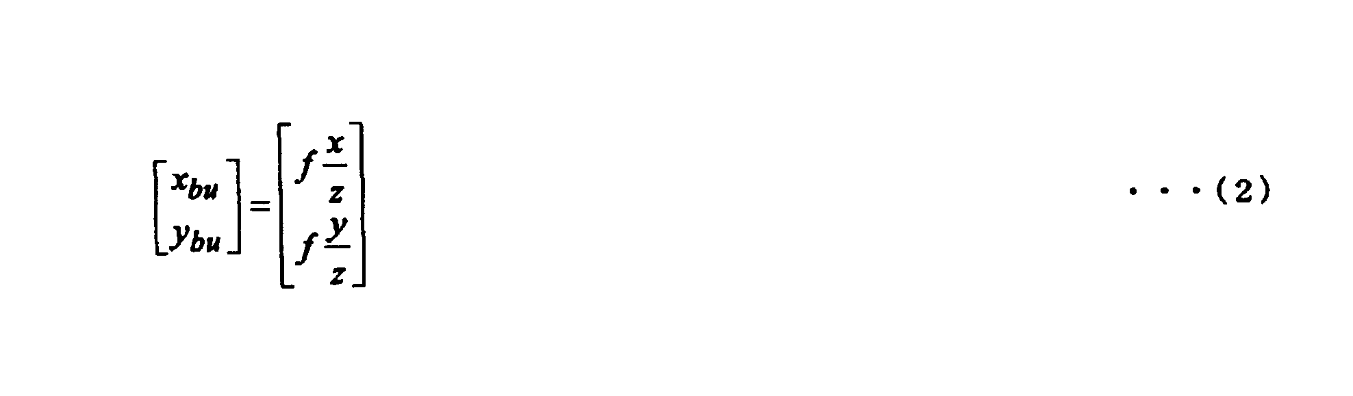
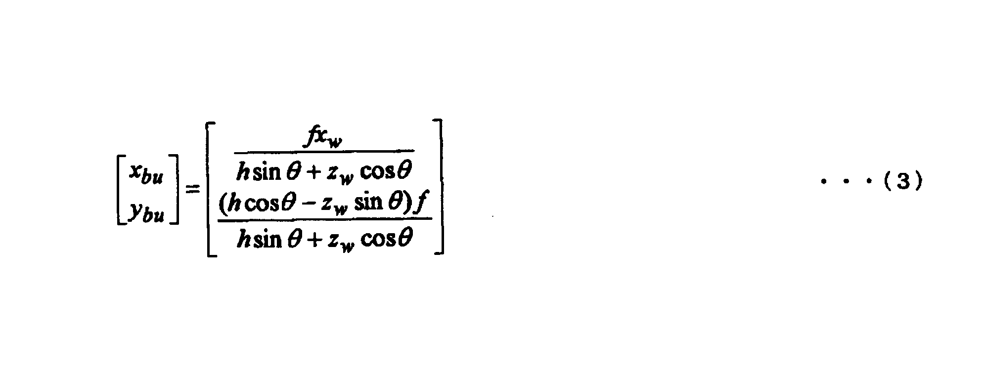
以下において、鳥瞰図座標系XauYauにおける座標(xau,yau)が撮像面Sの座標系XbuYbuにおける座標(xbu,ybu)とどのような関係式で表されるかについて説明する。
鳥瞰図画像は、実際のカメラの撮像画像を仮想視点の位置に存在する仮想的なカメラ(以下、仮想カメラと称する)の視点から見た画像に変換したものである。より具体的には、仮想カメラが地面上方に位置しかつその撮像方向が鉛直下向きであると捉え、鳥瞰図画像は、カメラの実際の撮像画像が地上面を鉛直方向に見下ろした画像に変換されたものである。撮像画像から鳥瞰図画像を生成する際の視点の変換は、一般に、視点変換と呼ばれる。
二次元地面座標系Xw Zw から仮想カメラの鳥瞰図座標系XauYauへの投影は、平行投影によって行われる。仮想カメラの高さ(即ち、仮想視点の高さ)をHとすると、二次元地面座標系Xw Zw の座標(xw ,zw )と鳥瞰図座標系XauYauの座標(xau,yau)との間の変換式は、次式(4)で表される。仮想カメラの高さHは予め設定されている。更に、式(4)を変形することにより、下式(5)が得られる。
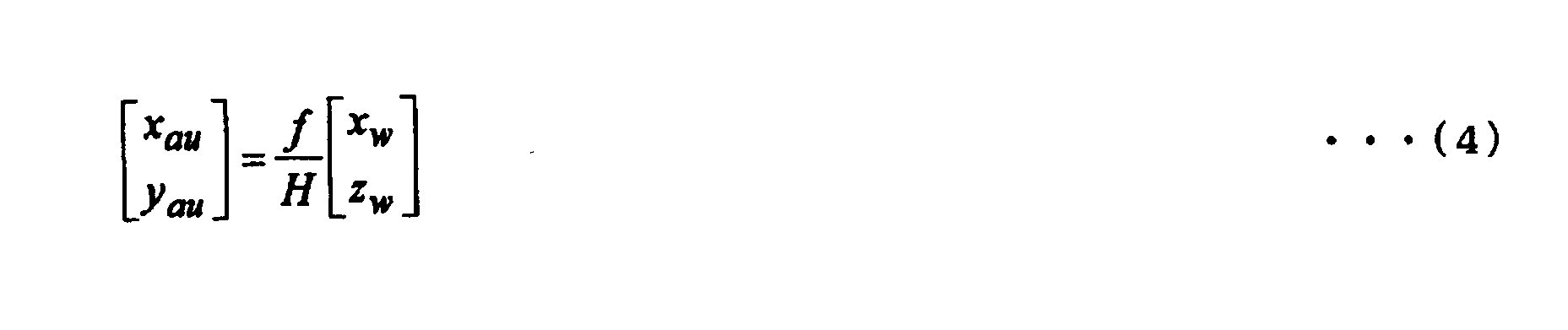


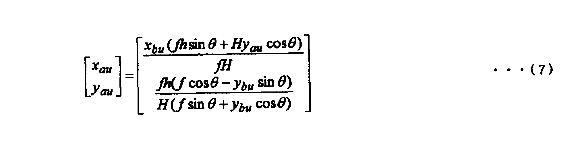
本発明の実施の形態は、特許請求の範囲に示された技術的思想の範囲内において、適宜、種々の変更が可能である。
本発明は、画像処理の分野に適用することができる。
Claims (6)
- 複数台の撮像装置によって撮像された画像の夫々を、仮想視点から見た鳥瞰図画像に変換する視点変換部と、
前記視点変換部で変換された各鳥瞰図画像を合成して合成鳥瞰図画像を生成する画像合成部と
を備えた画像処理装置であって、
前記鳥瞰図画像に基づいて障害物に関する障害物情報を抽出する障害物情報抽出部と、
前記障害物情報抽出部で抽出された前記障害物情報に基づいて、前記撮像装置によって撮像された画像から、前記障害物を含む画像である障害物原画像を抽出する障害物原画像抽出部と、
前記障害物情報抽出部で抽出された前記障害物情報に基づいて、前記合成鳥瞰図画像から、前記合成鳥瞰図画像の中の前記障害物に対応する障害物鳥瞰画像を検出する障害物鳥瞰画像検出部と、
前記障害物鳥瞰画像検出部で検出された前記障害物鳥瞰画像を前記障害物原画像抽出部で抽出された前記障害物原画像に置換した画像を置換合成鳥瞰図画像として出力する置換処理部と、
前記置換処理部から出力された前記置換合成鳥瞰図画像を表示装置に表示させるための映像データを生成する映像データ生成部と
を備えた画像処理装置。 - 前記障害物情報抽出部は、
前記複数台の撮像装置のうちの少なくとも2台の撮像装置である対象撮像装置によって撮像されている前記鳥瞰図画像である対象鳥瞰図画像の重なり合う領域の画像において、前記対象鳥瞰図画像間で差分処理を行うことで前記障害物情報を抽出する
請求項1に記載の画像処理装置。 - 複数台の撮像装置によって撮像された画像の夫々を、仮想視点から見た鳥瞰図画像に変換する視点変換部と、
前記視点変換部で変換された各鳥瞰図画像を合成して合成鳥瞰図画像を生成する画像合成部と
を備えた画像処理装置であって、
前記鳥瞰図画像に基づいて障害物に関する障害物情報を抽出する障害物情報抽出部と、
前記障害物情報抽出部で抽出された前記障害物情報に基づいて、前記合成鳥瞰図画像から、前記合成鳥瞰図画像の中の前記障害物に対応する障害物鳥瞰画像を検出する障害物鳥瞰画像検出部と、
前記障害物鳥瞰画像検出部で検出された前記障害物鳥瞰画像に関する情報に基づいて、前記撮像装置によって撮像された画像から、前記障害物を含む画像である障害物原画像を抽出し、前記障害物鳥瞰画像検出部で検出された前記障害物鳥瞰画像を前記障害物原画像に置換した画像を置換合成鳥瞰図画像として出力する置換処理部と、
前記置換処理部から出力された前記置換合成鳥瞰図画像を表示装置に表示させるための映像データを生成する映像データ生成部と
を備えた画像処理装置。 - 複数台の撮像装置によって撮像された画像の夫々を、仮想視点から見た鳥瞰図画像に変換する視点変換ステップと、
前記視点変換ステップで変換された各鳥瞰図画像を合成して合成鳥瞰図画像を生成する画像合成ステップと
を含む、コンピュータを画像処理装置として動作させる画像処理プログラムであって、
前記鳥瞰図画像に基づいて障害物に関する障害物情報を抽出する障害物情報抽出ステップと、
前記障害物情報抽出ステップで抽出された前記障害物情報に基づいて、前記撮像装置によって撮像された画像から、前記障害物を含む画像である障害物原画像を抽出する障害物原画像抽出ステップと、
前記障害物情報抽出ステップで抽出された前記障害物情報に基づいて、前記合成鳥瞰図画像から、前記合成鳥瞰図画像の中の前記障害物に対応する障害物鳥瞰画像を検出する障害物鳥瞰画像検出ステップと、
前記障害物鳥瞰画像検出部で検出された前記障害物鳥瞰画像を前記障害物原画像抽出部で抽出された前記障害物原画像に置換した画像を置換合成鳥瞰図画像として出力する置換処理ステップと、
前記置換処理ステップから出力された前記置換合成鳥瞰図画像を表示装置に表示させるための映像データを生成する映像データ生成ステップと
を含む画像処理プログラム。 - 請求項1ないし3の何れかに記載の画像処理装置と、
前記複数台の撮像装置、及び、前記表示装置を備えた
画像処理システム。 - 複数台の撮像装置によって撮像された画像の夫々を、仮想視点から見た鳥瞰図画像に変換し、変換された各鳥瞰図画像を合成して合成鳥瞰図画像を生成する画像処理方法であって、
前記鳥瞰図画像に基づいて障害物に関する障害物情報を抽出し、
抽出された前記障害物情報に基づいて、前記撮像装置によって撮像された画像から、前記障害物を含む画像である障害物原画像を抽出し、
抽出された前記障害物情報に基づいて、前記合成鳥瞰図画像から、前記合成鳥瞰図画像の中の前記障害物に対応する障害物鳥瞰画像を検出し、
前記障害物鳥瞰画像検出部で検出された前記障害物鳥瞰画像を前記障害物原画像抽出部で抽出された前記障害物原画像に置換した画像を置換合成鳥瞰図画像として出力させ、
出力された前記置換合成鳥瞰図画像を表示装置に表示させるための映像データを生成する
画像処理方法。
Applications Claiming Priority (2)
| Application Number | Priority Date | Filing Date | Title |
|---|---|---|---|
| JP2008-084963 | 2008-03-27 | ||
| JP2008084963A JP5422902B2 (ja) | 2008-03-27 | 2008-03-27 | 画像処理装置、画像処理プログラム、画像処理システム及び画像処理方法 |
Publications (1)
| Publication Number | Publication Date |
|---|---|
| WO2009119337A1 true WO2009119337A1 (ja) | 2009-10-01 |
Family
ID=41113535
Family Applications (1)
| Application Number | Title | Priority Date | Filing Date |
|---|---|---|---|
| PCT/JP2009/054843 Ceased WO2009119337A1 (ja) | 2008-03-27 | 2009-03-13 | 画像処理装置、画像処理プログラム、画像処理システム及び画像処理方法 |
Country Status (2)
| Country | Link |
|---|---|
| JP (1) | JP5422902B2 (ja) |
| WO (1) | WO2009119337A1 (ja) |
Cited By (7)
| Publication number | Priority date | Publication date | Assignee | Title |
|---|---|---|---|---|
| US8446471B2 (en) | 2009-12-31 | 2013-05-21 | Industrial Technology Research Institute | Method and system for generating surrounding seamless bird-view image with distance interface |
| JP2016013793A (ja) * | 2014-07-03 | 2016-01-28 | 株式会社デンソー | 画像表示装置、画像表示方法 |
| CN105574813A (zh) * | 2015-12-31 | 2016-05-11 | 青岛海信移动通信技术股份有限公司 | 一种图像处理方法和装置 |
| CN110084115A (zh) * | 2019-03-22 | 2019-08-02 | 江苏现代工程检测有限公司 | 基于多维信息概率模型的路面检测方法 |
| CN115244594A (zh) * | 2020-03-24 | 2022-10-25 | 三菱电机株式会社 | 信息处理装置和信息处理方法 |
| CN117953362A (zh) * | 2022-10-28 | 2024-04-30 | 广州视源电子科技股份有限公司 | 障碍物信息识别方法、装置、智能设备及存储介质 |
| WO2024234659A1 (zh) * | 2023-05-16 | 2024-11-21 | 惠州市德赛西威汽车电子股份有限公司 | 感知融合系统、电子设备和存储介质 |
Families Citing this family (10)
| Publication number | Priority date | Publication date | Assignee | Title |
|---|---|---|---|---|
| JP4786000B2 (ja) | 2009-10-16 | 2011-10-05 | 株式会社カネカ | 還元型補酵素q10の製造方法、安定化方法及びそれを含有する組成物 |
| JP5503259B2 (ja) | 2009-11-16 | 2014-05-28 | 富士通テン株式会社 | 車載照明装置、画像処理装置及び画像表示システム |
| JP5299296B2 (ja) * | 2010-01-26 | 2013-09-25 | 株式会社デンソーアイティーラボラトリ | 車両周辺画像表示装置及び車両周辺画像表示方法 |
| JP5679763B2 (ja) * | 2010-10-27 | 2015-03-04 | ルネサスエレクトロニクス株式会社 | 半導体集積回路及び全周囲映像システム |
| JP5575703B2 (ja) * | 2011-06-07 | 2014-08-20 | 株式会社小松製作所 | ダンプトラックの積載量表示装置 |
| TWI552907B (zh) * | 2013-10-30 | 2016-10-11 | 緯創資通股份有限公司 | 行車安全輔助系統和方法 |
| CN104506795A (zh) * | 2014-12-05 | 2015-04-08 | 苏州阔地网络科技有限公司 | 一种数据切换方法及系统 |
| EP3267680A4 (en) * | 2015-03-03 | 2018-10-03 | Hitachi Construction Machinery Co., Ltd. | Device for monitoring surroundings of vehicle |
| CN106101540B (zh) | 2016-06-28 | 2019-08-06 | 北京旷视科技有限公司 | 对焦点确定方法及装置 |
| JP6586051B2 (ja) * | 2016-06-30 | 2019-10-02 | 株式会社 日立産業制御ソリューションズ | 画像処理装置および画像処理方法 |
Citations (5)
| Publication number | Priority date | Publication date | Assignee | Title |
|---|---|---|---|---|
| JPH08305999A (ja) * | 1995-05-11 | 1996-11-22 | Hitachi Ltd | 車載用カメラシステム |
| JP2006253872A (ja) * | 2005-03-09 | 2006-09-21 | Toshiba Corp | 車両周辺画像表示装置および車両周辺画像表示方法 |
| JP2006341641A (ja) * | 2005-06-07 | 2006-12-21 | Nissan Motor Co Ltd | 映像表示装置及び映像表示方法 |
| JP2007027948A (ja) * | 2005-07-13 | 2007-02-01 | Nissan Motor Co Ltd | 車両周辺監視装置及び車両周辺監視方法 |
| JP2008048094A (ja) * | 2006-08-14 | 2008-02-28 | Nissan Motor Co Ltd | 車両用映像表示装置及び車両周囲映像の表示方法 |
-
2008
- 2008-03-27 JP JP2008084963A patent/JP5422902B2/ja not_active Expired - Fee Related
-
2009
- 2009-03-13 WO PCT/JP2009/054843 patent/WO2009119337A1/ja not_active Ceased
Patent Citations (5)
| Publication number | Priority date | Publication date | Assignee | Title |
|---|---|---|---|---|
| JPH08305999A (ja) * | 1995-05-11 | 1996-11-22 | Hitachi Ltd | 車載用カメラシステム |
| JP2006253872A (ja) * | 2005-03-09 | 2006-09-21 | Toshiba Corp | 車両周辺画像表示装置および車両周辺画像表示方法 |
| JP2006341641A (ja) * | 2005-06-07 | 2006-12-21 | Nissan Motor Co Ltd | 映像表示装置及び映像表示方法 |
| JP2007027948A (ja) * | 2005-07-13 | 2007-02-01 | Nissan Motor Co Ltd | 車両周辺監視装置及び車両周辺監視方法 |
| JP2008048094A (ja) * | 2006-08-14 | 2008-02-28 | Nissan Motor Co Ltd | 車両用映像表示装置及び車両周囲映像の表示方法 |
Cited By (9)
| Publication number | Priority date | Publication date | Assignee | Title |
|---|---|---|---|---|
| US8446471B2 (en) | 2009-12-31 | 2013-05-21 | Industrial Technology Research Institute | Method and system for generating surrounding seamless bird-view image with distance interface |
| JP2016013793A (ja) * | 2014-07-03 | 2016-01-28 | 株式会社デンソー | 画像表示装置、画像表示方法 |
| CN105574813A (zh) * | 2015-12-31 | 2016-05-11 | 青岛海信移动通信技术股份有限公司 | 一种图像处理方法和装置 |
| CN105574813B (zh) * | 2015-12-31 | 2019-03-01 | 青岛海信移动通信技术股份有限公司 | 一种图像处理方法和装置 |
| CN110084115A (zh) * | 2019-03-22 | 2019-08-02 | 江苏现代工程检测有限公司 | 基于多维信息概率模型的路面检测方法 |
| CN115244594A (zh) * | 2020-03-24 | 2022-10-25 | 三菱电机株式会社 | 信息处理装置和信息处理方法 |
| CN115244594B (zh) * | 2020-03-24 | 2023-10-31 | 三菱电机株式会社 | 信息处理装置和信息处理方法 |
| CN117953362A (zh) * | 2022-10-28 | 2024-04-30 | 广州视源电子科技股份有限公司 | 障碍物信息识别方法、装置、智能设备及存储介质 |
| WO2024234659A1 (zh) * | 2023-05-16 | 2024-11-21 | 惠州市德赛西威汽车电子股份有限公司 | 感知融合系统、电子设备和存储介质 |
Also Published As
| Publication number | Publication date |
|---|---|
| JP5422902B2 (ja) | 2014-02-19 |
| JP2009239754A (ja) | 2009-10-15 |
Similar Documents
| Publication | Publication Date | Title |
|---|---|---|
| JP5422902B2 (ja) | 画像処理装置、画像処理プログラム、画像処理システム及び画像処理方法 | |
| JP5444338B2 (ja) | 車両周囲監視装置 | |
| CN100438623C (zh) | 图象处理装置及监视系统 | |
| JP5320970B2 (ja) | 車両用表示装置および表示方法 | |
| JP3300334B2 (ja) | 画像処理装置および監視システム | |
| JPWO2017122294A1 (ja) | 周囲監視装置、画像処理方法、及び画像処理プログラム | |
| CN102792685B (zh) | 处理对象图像生成装置、处理对象图像生成方法及操作支持系统 | |
| JPWO2000064175A1 (ja) | 画像処理装置および監視システム | |
| JP2006287892A (ja) | 運転支援システム | |
| JP2010093605A (ja) | 操縦支援装置 | |
| JP2008083786A (ja) | 画像生成装置および画像生成方法 | |
| JP2009524171A (ja) | 複数の画像を結合して鳥瞰図画像にする方法 | |
| WO2009119110A1 (ja) | 死角表示装置 | |
| JP4907883B2 (ja) | 車両周辺画像表示装置および車両周辺画像表示方法 | |
| JP6958163B2 (ja) | 表示制御装置 | |
| JP4248570B2 (ja) | 画像処理装置並びに視界支援装置及び方法 | |
| JP2010141836A (ja) | 障害物検知装置 | |
| CN104735403B (zh) | 车用障碍物侦测显示系统 | |
| JP4315968B2 (ja) | 画像処理装置並びに視界支援装置及び方法 | |
| JP2009105660A (ja) | 車載用撮像装置 | |
| JP6167824B2 (ja) | 駐車支援装置 | |
| CN115996864A (zh) | 显示控制装置、车辆及显示控制方法 | |
| JP2010258691A (ja) | 操縦支援装置 | |
| JP4606322B2 (ja) | 車両運転支援装置 | |
| JP5861871B2 (ja) | 俯瞰画像提示装置 |
Legal Events
| Date | Code | Title | Description |
|---|---|---|---|
| 121 | Ep: the epo has been informed by wipo that ep was designated in this application |
Ref document number: 09725382 Country of ref document: EP Kind code of ref document: A1 |
|
| NENP | Non-entry into the national phase |
Ref country code: DE |
|
| 122 | Ep: pct application non-entry in european phase |
Ref document number: 09725382 Country of ref document: EP Kind code of ref document: A1 |