WO2009113144A1 - Dispositif de localisation de sujet et procédé de localisation de sujet - Google Patents
Dispositif de localisation de sujet et procédé de localisation de sujet Download PDFInfo
- Publication number
- WO2009113144A1 WO2009113144A1 PCT/JP2008/004015 JP2008004015W WO2009113144A1 WO 2009113144 A1 WO2009113144 A1 WO 2009113144A1 JP 2008004015 W JP2008004015 W JP 2008004015W WO 2009113144 A1 WO2009113144 A1 WO 2009113144A1
- Authority
- WO
- WIPO (PCT)
- Prior art keywords
- image
- contour
- search
- processing
- edge
- Prior art date
Links
Images


Classifications
-
- G—PHYSICS
- G06—COMPUTING; CALCULATING OR COUNTING
- G06T—IMAGE DATA PROCESSING OR GENERATION, IN GENERAL
- G06T7/00—Image analysis
- G06T7/20—Analysis of motion
- G06T7/277—Analysis of motion involving stochastic approaches, e.g. using Kalman filters
-
- G—PHYSICS
- G06—COMPUTING; CALCULATING OR COUNTING
- G06T—IMAGE DATA PROCESSING OR GENERATION, IN GENERAL
- G06T7/00—Image analysis
- G06T7/20—Analysis of motion
- G06T7/246—Analysis of motion using feature-based methods, e.g. the tracking of corners or segments
- G06T7/251—Analysis of motion using feature-based methods, e.g. the tracking of corners or segments involving models
-
- G—PHYSICS
- G06—COMPUTING; CALCULATING OR COUNTING
- G06T—IMAGE DATA PROCESSING OR GENERATION, IN GENERAL
- G06T2207/00—Indexing scheme for image analysis or image enhancement
- G06T2207/10—Image acquisition modality
- G06T2207/10016—Video; Image sequence
Definitions
- the present invention relates to information processing technology, and more particularly, to an object tracking device for tracking an object in an input image and an object tracking method executed there.
- Visual tracking has a wide range of applications such as computer vision, especially visual surveillance in the security field, analysis / classification, editing of recorded video in the AV field, man-machine interface, and human-to-human interface, that is, video conferencing and videophone. Expected. Therefore, many studies have been made for the purpose of improving tracking accuracy and processing efficiency. In particular, much research has been done on the application of particle filters, which are attracting attention as a time-series analysis method for signals with added non-Gaussian noise that cannot be handled by Kalman filters, especially for the Condensation (Conditional (Density Propagation) algorithm. Is famous (see, for example, Non-Patent Document 1 to Non-Patent Document 3).
- the particle filter is an approximate calculation method of the Bayes filter, and expresses a target probability distribution by introducing a finite number of particles as tracking candidates, and performs time series estimation and prediction using the target probability distribution.
- the Condensation algorithm uses a particle filter to estimate the temporal change of the probability distribution for the shape of the tracking target. Specifically, the contour line of a candidate having the same shape as the tracking target is represented by one particle, and the existence probability distribution in the target parameter space is calculated by calculating the likelihood of the parameter transition by the motion model and the transition result by the observation. Estimate sequentially. Contour tracking by stochastic propagation of conditional density, Michael Isard and Andrew Blake, Proc.European Conf. On Computer Vision, vol.
- the present invention has been made in view of such problems, and it is an object of the present invention to provide a visual tracking technique with high scalability, in which the efficiency of tracking processing is not easily affected by changes in the tracking target.
- An aspect of the present invention relates to an object tracking device.
- This object tracking device estimates the presence of an object in a first image frame out of a first image frame and a second image frame included in an image stream constituting moving image data obtained by capturing an object to be tracked. Based on the probability distribution, the candidate contour determination unit for determining the candidate contour of the object in the second image frame, the candidate contour determined by the candidate contour determination unit, and the edge image of the second image frame are matched to obtain a candidate An observation unit for observing the likelihood of the contour, and a result acquisition unit for estimating the existence probability distribution of the object in the second image frame based on the likelihood observed by the observation unit.
- a plurality of search units that execute the process of searching for the nearest edge from the knots constituting the curve of the curve in parallel for each knot, and the results searched by the search unit are integrated for each candidate contour Characterized by comprising the likelihood acquisition unit for obtaining the likelihood, the.
- first image frame and the “second image frame” may be adjacent image frames in the image stream or may be image frames positioned apart from each other.
- first image frame is an image frame temporally prior to the “second image frame”. Is not limited to this.
- the “existence probability distribution” may be an existence probability distribution with respect to the position coordinates in the image frame of the object, and a parameter representing any of the attributes of the object such as shape, color, size, or a combination thereof. It may be an existence probability distribution for the extended space.
- a “candidate contour” is a graphic representing a candidate for a contour line of a part or the whole of an object.
- the “likelihood” is a degree representing how close the candidate contour is to the object, for example, a numerical value indicating the degree of overlap with the object, the distance from the object, and the like.
- Another aspect of the present invention relates to an object tracking method.
- This object tracking method estimates the presence of an object in the first image frame out of the first image frame and the second image frame included in the image stream constituting the moving image data obtained by capturing the object to be tracked. Determining a candidate contour of the object in the second image frame based on the probability distribution, generating an edge image of the second image frame and storing it in a memory, and a portion of the edge image stored in the memory.
- the process of detecting the nearest edge from the knots that make up the curve of the candidate contour by reading and searching the image data of the region and integrating the result of edge detection with the step of executing in parallel for each knot Obtaining likelihood for each candidate contour, and estimating the existence probability distribution of the object in the second image frame.
- a high-speed and highly scalable visual tracking technique can be realized.
- FIG. 1 is a diagram illustrating a configuration example of a visual tracking system in Embodiment 1.
- FIG. It is a figure which shows the structure of the tracking apparatus in Embodiment 1 in detail.
- 3 is a flowchart showing a procedure of tracking processing in the first embodiment.
- FIG. 3 is a diagram illustrating the configuration of an observation unit in the first embodiment in more detail.
- FIG. 6 is a diagram schematically showing a state in which image data of a region cut out from a contour image stored in an image storage unit in the first embodiment is copied to each local memory.
- FIG. 6 is a diagram schematically illustrating a process transition when the first processing unit, the second processing unit,..., The Nth processing unit of the contour search unit perform the contour search processing in the first embodiment.
- 3 is a diagram illustrating a detailed configuration of a contour image generation unit according to Embodiment 1.
- FIG. It is a figure for demonstrating the difference of a general edge extraction process and the outline image generation process in this Embodiment. It is a figure which shows the example of the original image which is a process target. It is a figure which shows the edge image produced
- FIG. 12 is a diagram showing a gradation-reduced image obtained as an intermediate image when the contour image generation process of the present embodiment is performed on the original image shown in FIG. 11 in the first embodiment. It is a figure which shows the outline image produced
- FIG. 10 is a diagram schematically showing a state in which image data of a divided region is copied from each contour image stored in an image storage unit to each local memory in the second embodiment.
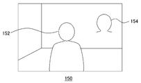
- FIG. 1 is a diagram for explaining a visual tracking method when a person is a tracking target.
- the person image 150 is one of the image frames constituting the image stream of the moving image generated by the moving image or the computer graphics that is actually captured, and the person 152 to be tracked is captured.
- an ⁇ -shaped curve 154 that approximates the shape of the head contour of the person 152 is described in a known expression.
- the person image 150 including the person 152 is subjected to edge extraction processing to obtain an edge image. Then, by changing the shape and position while changing the parameter defining the curve 154 and searching for an edge in the vicinity thereof, the value of the parameter estimated to be the best match with the head contour of the person 152 is specified.
- the tracking of the person 152 progresses by repeating the above processing for each frame.
- the edge generally refers to a portion having an abrupt change in image density or color.
- a probability distribution prediction technique using a particle filter is introduced.
- the number of samplings of the curve 154 is increased or decreased according to the probability distribution of the object in the parameter space in the immediately preceding frame, and the tracking candidates are narrowed down.
- Non-Patent Document 3 (ICondensation: Unifying low-level and high-level tracking in a stochastic framework, Michael Isard and Andrew Blake, Proc 5th European Conf. Computer Vision, 1998).
- the description will be focused on the points according to the present embodiment.
- the ⁇ -shaped curve 154 is described as a B-spline curve.
- the B-spline curve is defined by n control point sequences (Q0,..., Qn) and knot sequences (s0,..., Sn). These parameters are set in advance so as to form a basic curve shape, in this case, an ⁇ -shaped curve.
- the curve obtained by the setting at this time is hereinafter referred to as template Q0.
- the template Q0 has an ⁇ shape, but the shape is changed depending on the tracking target. That is, if the tracking target is a ball, the shape is circular, and if the tracking target is a palm, the shape is a hand.
- a shape space vector x is prepared as a conversion parameter for changing the shape of the template.
- the shape space vector x is composed of the following six parameters.
- (shift x , shift y ) is a translation amount in the (x, y) direction
- (extend x , extend y ) is a magnification
- ⁇ is a rotation angle.
- the template can be translated, stretched and rotated by appropriately changing the six parameters constituting the shape space vector x, and the shape and position of the candidate curve Q can be changed variously depending on the combination. it can.
- a plurality of candidate curves expressed by changing the parameters of the template Q 0 such as the interval between the control point sequence and the knot sequence and the six parameters constituting the shape space vector x are persons in the vicinity of each knot. Search for 152 edges. Thereafter, the likelihood density distribution in the six-dimensional space spanned by the six parameters constituting the shape space vector x is estimated by obtaining the likelihood of each candidate curve from the distance to the edge or the like.
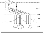
- FIG. 2 is a diagram for explaining a probability density distribution estimation method using a particle filter.
- the change of a certain parameter x1 is shown on the horizontal axis, but actually the same processing is performed in the 6-dimensional space. Is called.
- the image frame whose probability density distribution is to be estimated is the image frame at time t.
- a particle is a materialization of the value of the parameter x1 to be sampled and the sampling density. For example, in the region of the parameter x1, where the probability density was high at time t-1, sampling is performed by increasing the particle density. In the range where the probability density is low, sampling is not performed by reducing the number of particles. Thereby, for example, many candidate curves are generated near the edge of the person 152, and matching is performed efficiently.
- the predetermined motion model is, for example, a Gaussian motion model, an autoregressive prediction motion model, or the like.
- the former is a model in which the probability density at time t is Gaussian distributed around each probability density at time t-1.
- the latter is a method that assumes a second-order or higher-order autoregressive prediction model acquired from sample data. For example, it is estimated from a change in past parameters that a person 152 is moving at a certain speed. In the example of FIG. 2, the motion in the positive direction of the parameter x1 is estimated by the autoregressive prediction type motion model, and each particle is changed in that way.
- the likelihood of each candidate curve is obtained by searching for the edge of the person 152 in the vicinity of the candidate curve determined by each particle using the edge image at time t, and the probability density distribution at time t is obtained.
- Estimate (S16) As described above, the probability density distribution at this time is a discrete representation of the true probability density distribution 400 as shown in S16. Thereafter, by repeating this, the probability density distribution at each time is represented in the parameter space. For example, if the probability density distribution is unimodal, that is, if the tracked object is unique, the final parameter is the weighted sum of each parameter value using the obtained probability density. Thus, the contour curve closest to the tracking target is obtained.
- the probability density distribution p (x t i ) at time t estimated in S16 is calculated as follows.
- i is a number uniquely given to a particle
- x t i , u t ⁇ 1 ) is a predetermined motion model
- x t i ) is a likelihood.
- FIG. 3 shows a configuration example of the visual tracking system in the present embodiment.
- the visual tracking system 10 includes an imaging device 12 that images the tracking target 18, a tracking device 14 that performs tracking processing, and a display device 16 that outputs image data captured by the imaging device 12 and tracking result data.
- the tracking target 18 may vary depending on the purpose of use of the visual tracking system 10 such as a person, an object, or a part thereof, but in the following description, it is assumed that the person is a person as in the above example.
- connection between the tracking device 14 and the imaging device 12 or the display device 16 may be wired or wireless, and may be via various networks. Alternatively, any two or all of the imaging device 12, the tracking device 14, and the display device 16 may be combined and integrally provided. Depending on the usage environment, the imaging device 12 and the display device 16 may not be connected to the tracking device 14 at the same time.
- the imaging device 12 acquires data of an image including the tracking target 18 or an image of a certain place regardless of the presence or absence of the tracking target 18 at a predetermined frame rate.
- the acquired image data is input to the tracking device 14, and the tracking processing of the tracking target 18 is performed.
- the processing result is output as output data to the display device 16 under the control of the tracking device 14.
- the tracking device 14 may also serve as a computer that performs another function, and may implement various functions by using data obtained as a result of the tracking process, that is, position information and shape information of the tracking target 18. .
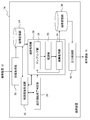
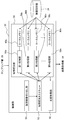
- FIG. 4 shows the configuration of the tracking device 14 in the present embodiment in detail.
- the tracking device 14 includes an image acquisition unit 20 that acquires input image data input from the imaging device 12, an image storage unit 24 that stores the input image data and the contour image data, and a contour image that generates a contour image from the input image data.
- a generation unit 22 a tracking start / end determination unit 28 that determines the start and end of tracking, a tracking processing unit 26 that performs tracking processing using a particle filter, a result storage unit 36 that stores final tracking result data, and a tracking result
- the output control part 40 which controls the output to the display apparatus 16 is included.
- each element described as a functional block for performing various processes can be configured with a CPU, a memory, and other LSIs in terms of hardware, and a program for performing image processing in terms of software. It is realized by. Therefore, it is understood by those skilled in the art that these functional blocks can be realized in various forms by hardware only, software only, or a combination thereof, and is not limited to any one.
- the contour image generation unit 22 extracts the contour line to be tracked from the image frame of the input image, and generates a contour image.
- the contour image is stored in the image storage unit 24 and later used in the observation of the candidate curve in the observation unit 30 of the tracking processing unit 26.
- “contour lines” are treated as “edges” in an edge image, and thus, with the conventional technique, likelihood observation using an “edge image” has been performed.
- edge extraction filters many edges are extracted in addition to the contour line of an object depending on the input image, so it is considered that likelihood observation cannot be performed accurately due to matching with edges other than the contour line. It is done. Further, if the threshold value for edge extraction is set high and the number of edges is reduced, the contour line is cut off, and there is a possibility that the likelihood observation is not accurately performed.
- the contour image generation unit 22 generates not only a general “edge image” but also an image that can accurately perform likelihood observation by focusing on the “contour” of an object in the input image. To do. Although a specific method will be described later, in the following description, an image generated by the contour image generation unit 22 is distinguished from a general “edge image” as a “contour image”. Further, the contour image generation unit 22 may be mounted with a foreground extractor (not shown) using a background difference. Then, the contour of the tracking target may be efficiently extracted by extracting the foreground including the tracking target from the input image as preprocessing of the contour image generation processing.
- the tracking start / end determining unit 28 evaluates, for example, the contour line or the foreground shape obtained by the contour image generating unit 22 and determines whether to start or end tracking according to a predetermined condition.
- end may include a temporary stop of tracking by occlusion or the like. Tracking starts when the tracking target appears within the viewing angle of the imaging device or when it appears from behind the object, etc.When the tracking target leaves the viewing angle of the imaging device or enters the shadow, etc. To finish. When it is determined that the tracking is to be started, the tracking processing unit 26 is notified to that effect and the tracking process is started.
- the tracking processing unit 26 includes a sampling unit 29, an observation unit 30, and a result acquisition unit 34.
- the sampling unit 29 performs particle generation and extinction processing based on the probability density distribution estimated for the previous image frame at time t-1. Then, a predetermined motion model is applied to all the particles to cause the particles to transition on the parameter space. Thereby, a plurality of candidate curves in the image frame at time t are determined.
- the sampling unit 29 starts the process when receiving a signal indicating the start of tracking from the tracking start / end determining unit 28, and ends the process when receiving a signal indicating the end of tracking.
- the observation unit 30 observes the likelihood of the candidate curve defined by each particle generated, disappeared, and transitioned by the sampling unit. For example, when the candidate curve defined by each particle is expressed by a B-spline curve, for each knot of the B-spline curve, the nearest contour line is searched for in the contour image generated by the contour image generation unit 22 to obtain the distance. To score the knots according to a predetermined rule. Then, the likelihood of the candidate curve is obtained based on the scores of all knots constituting the candidate curve. The observation unit 30 executes this search process in parallel using a plurality of processor units.
- a processing unit obtained by dividing the contour search processing for each knot is used as one processing unit, and a plurality of processor units perform parallel processing.
- Each processor unit copies only the image data of a part of the contour image including the knot and the search region to the subordinate local memory in order to search for the contour line closest to one knot. .
- the number of processing units of (number of particles) ⁇ (number of knots constituting candidate curve) is processed in a short time for each tracking target.
- the score of each knot acquired in parallel by each processor unit is integrated for each candidate curve, and the likelihood is calculated. Conventional techniques can be used for scoring and likelihood calculation.
- the result acquisition unit 34 calculates a probability density distribution p (x t i ) as shown in Expression 3 based on the likelihood observed by the observation unit 30, and tracks the curve data obtained by the weighted average parameter.
- the result is calculated and stored in the result storage unit 36.
- the data is returned to the sampling unit 29 for use in the tracking process at the next time t + 1.
- the data stored in the result storage unit 36 may be the value of each parameter that has been weighted and averaged, and may be any of an image composed only of a curve determined by that, or image data formed by combining a curve and an input image But you can.
- the result acquisition unit 34 may further track each tracking target using a template prepared for each, and combine the tracking results into one tracking result. Further, a case where a plurality of tracking targets overlap is detected based on the tracking result, and the tracking target hidden behind is taken out of the tracking processing target at a predetermined timing. As a result, even if the observation likelihood is temporarily lowered due to the tracking target moving behind another tracking target, it is possible to avoid outputting an inappropriate tracking result.
- the result storage unit 36 stores, for example, moving image data including the tracking result.
- the result storage unit 36 stores, for example, moving image data including the tracking result.
- the display device 16 by outputting the moving image data to the display device 16 under the control of the output control unit 40, it is possible to display how the curve of the template moves in the same manner as the movement of the tracking target.
- processing such as output to another arithmetic module may be appropriately performed according to the purpose of tracking.
- the imaging device 12 captures a place to be captured at a predetermined frame rate.
- the captured image is input as input image data to the image acquisition unit 20 of the tracking device 14 and stored in the image storage unit 24. In such a state, the following tracking process is performed.
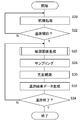
- FIG. 5 is a flowchart showing the procedure of the tracking process in the present embodiment.
- the tracking target is a person
- an ⁇ -type template is prepared for the tracking device 14 as described above.
- the template expression method is not limited to the B-spline curve, but may be any description format that can express a desired curve.
- the template shape deformation method may be appropriately selected from methods that can be adapted to the description format and that can be flexibly deformed as described above by changing several types of parameters.
- the tracking start / end determination unit 28 reads the input image data stored in the image storage unit 24 for each frame and determines whether or not to start tracking (S20, S22). For example, when an object having a predetermined size and shape that can be estimated as a person appears as a foreground extracted from an image frame, it is determined to start tracking.
- the size and shape of the foreground used as a judgment criterion are determined in advance logically or experimentally.
- Foreground extraction processing may use a foreground extractor (not shown) mounted on the contour image generation unit 22. In this case, the tracking start / end determining unit 28 requests the contour image generating unit 22 for foreground extraction processing.
- the tracking start / end determination unit 28 may be equipped with a foreground extractor.
- the tracking processing unit 26 starts the tracking process.
- the sampling unit 29 requests the contour image generation unit 22 for a contour image generation process
- the sampling unit 29 may also request a contour image generation process for the subsequent frame, and the contour image generation unit 22 may sequentially perform the process.
- the sampling unit 29 performs sampling by arranging particles evenly in a predetermined region of the parameter space, for example, and the observation unit 30 observes the likelihood by matching the candidate curve defined by each particle and the contour image, and the result
- the acquisition unit 34 calculates the initial value p (x 0 i ) of the rate density distribution using Equation 3 (S28, S30, S32).
- the sampling unit 29 generates a number of particles corresponding to the generated initial value p (x 0 i ) of the probability density distribution on the parameter space, and performs sampling by transitioning the particles based on a predetermined motion model ( S28).
- the number of particles to be generated is controlled in consideration of the processing load based on the amount of computation resources of the tracking device 14 and the required result output speed.
- a motion model that can be obtained with high tracking accuracy from a Gaussian motion model, an autoregressive motion model, or the like is determined in advance according to the type of tracking target.
- the observation unit 30 observes the likelihood p (y t
- search processing is allocated to a plurality of processors for each knot. Details will be described later.
- the tracking start / end determining unit 28 determines whether to continue or end the tracking process (S34). For example, the tracking end is determined when a target having a predetermined size and shape that can be estimated as a person does not appear as a foreground for a predetermined time. Alternatively, the end of tracking is determined when the occlusion state continues for a predetermined time, such as when a tracking target in real space moves behind another tracking target. The occlusion state may be estimated from past tracking processing results, or may be detected by a distance measurement system (not shown). Further, a situation in which the tracking target deviates from the angle of view of the imaging device 12 continues for a predetermined time is also detected by a method similar to occlusion and the tracking end is determined.
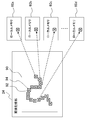
- FIG. 6 shows the configuration of the observation unit 30 in more detail.
- the observation unit 30 includes a contour image cutout unit 50, a contour search task queue 52, a contour search unit 56, and a likelihood acquisition unit 54.
- the contour image cutout unit 50 cuts out a region corresponding to each knot from the contour image based on the knot coordinates of the curve representing the candidate curve.
- the area corresponding to each knot is an area including the knot and a search area for the knot. It may be equal to the search area, and is also referred to as “search area” in the following description.
- a processing request for contour search including coordinate information of knots and information related to the corresponding region is issued. The issued processing request is added to the processing queue in the contour search task queue 52.
- the contour search unit 56 includes N processing units of a first processing unit 58a, a second processing unit 58b, a third processing unit 58c,..., An Nth processing unit 58n, and local memories 60a and 60b connected to the N processing units. , 60c, ..., 60n.
- Each processing unit sequentially reads out contour search processing requests from the contour search task queue 52 and executes the contour search processing for the requested knots. Specifically, the image data of the area specified by the processing request is copied from the contour image stored in the image storage unit 24 to the subordinate local memory. Based on the coordinates of the designated knot, the contour line closest to the knot is searched in the area copied to the local memory and scored according to a predetermined rule.
- a generally used edge search technique can be used for contour search.
- the search area can be determined by the selected search method and the accuracy required for matching.
- the N-th processing unit 58n executes one processing request, the obtained score is output to the likelihood acquisition unit 54. To do. Then, the next contour search processing request is read from the contour search task queue 52, and the same processing is repeated.
- the likelihood acquisition unit 54 integrates the scores of the knots respectively input from the first processing unit 58a, the second processing unit 58b, the third processing unit 58c, ..., the N-th processing unit 58n of the contour search unit.
- the likelihood for each candidate curve is calculated.
- the scores of all knots constituting the candidate curve are collected and summed, an average value is calculated, or substituted into a predetermined conversion formula.
- the scores for the knots are output one after another from each processing unit of the contour search unit 56, and information that associates the identification information of the knots with the identification information of the candidate curve to which the knot belongs is shared in the observation unit 30.
- the result can be integrated for each candidate curve by storing it and including necessary identification information when processing requests and scores are output.
- FIG. 6 schematically shows how the image data of the designated area is copied from the contour image to the local memories 60a, 60b, 60c,.
- the image storage unit 24 stores a contour image 90 generated by the contour image generation unit 22.
- the coordinates of the knots 92 of the candidate curve are determined by the particles determined by the sampling unit 29.
- the contour image cutout unit 50 When the contour image cutout unit 50 acquires the coordinates of the knots 92, the contour image cutout unit 50 cuts out the search area 94 of the knots for each knot.
- the search area is determined in consideration of accuracy, memory capacity, processing speed, and the like. In the example of FIG. 7, a square whose center of gravity is the coordinate of the knot 92 is cut out as the search area 94. From the viewpoint of search accuracy, it is desirable to change the size of the search area 94 according to the size of the candidate curve. For example, the maximum data size of the search area 94 with respect to the maximum size that can be taken by the candidate curve is set to be equal to the maximum data size that can be stored in the copy areas of the local memories 60a, 60b, 60c,.
- the size of the square is determined by changing the search area 94 according to the ratio of the sizes of the candidate curves.
- the size of the candidate curve can be determined based on the magnification (extend x , extend y ) among the parameters of each particle.
- the method of determining the search area 94 is not limited to that shown in FIG. As described later, the time may be increased or decreased in consideration of the time for copying the image data of the area to the local memories 60a, 60b, 60c,.
- the center of gravity of the search area 94 may not have knots.
- the movement of the tracking target may be estimated using an autoregressive prediction model used when the particles are transitioned by the motion model, and the search region 94 may be provided widely in the direction estimated to move.
- the search area 94 may not be a square, and may be other rectangles, rhombuses, horizontal and vertical lines of pixels, etc., depending on the search method and the characteristics of movement of the tracking target.
- the contour image cutout unit 50 puts a contour search processing request including the coordinates of the knot 92 and the information of the search area 94 corresponding thereto, for example, the coordinates of one corner of the square and the length of one side into the contour search task queue 52.
- the Nth processing unit 58n of the contour search unit read one contour search processing request from the contour search task queue 52, Based on the square information included in the request, only the image data of the square area is copied from the contour image 90 stored in the image storage unit 24 to the subordinate local memory.
- the amount of data required for one processing unit is limited by setting the processing unit to each knot.
- dividing the processing for each knot significantly reduces the amount of data in the search area and affects the size of the candidate curve. It is hard to receive.
- storage in the local memory is possible regardless of the size of the tracking target.
- the local memory generally has a small capacity and can be accessed at high speed. Therefore, by defining a search area for each knot and copying only the image data in that area, high-speed tracking processing can be performed along with the effect of parallel processing. This effect can be obtained by any information processing apparatus having a plurality of processors. In particular, such a configuration facilitates application to an information processing apparatus that implements “heterogeneous multi-core”.
- Heterogeneous multi-core is an information processing device that mounts different types of cores, and has the characteristics that the memory capacity used by each core is small and that data necessary for processing needs to be copied to the memory of each core.
- the search area 94 is defined as described above, the size of the image data can be made smaller than the memory capacity of each core.
- the present embodiment can be applied to the heterogeneous multi-core, and high-speed tracking processing can be realized without limiting the apparatus.
- any of the plurality of processor units that realize the functions of the first processing unit 58a to the Nth processing unit 58n included in the contour search unit 56 may also serve as the contour image cutout unit 50 and the likelihood acquisition unit 54.
- each function other than the observation unit 30 included in the tracking device 14 may be realized by any one of the plurality of processor units.
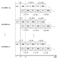
- FIG. 8 schematically shows a process transition when the first processing unit 58a, the second processing unit 58b,..., And the Nth processing unit 58n of the contour searching unit 56 perform the contour searching process.
- the right direction of the figure is the time axis, and from time T1, the N processing units of the first processing unit 58a to the N-th processing unit 58n perform knot 1, knot 2, ..., knot N of a certain candidate curve.
- Execute search processing request When the search processing request is read from the contour search task queue 52, each processing unit copies the image data of the area specified by the search processing request from the contour image in the image storage unit 24 to the subordinate local memory and starts the search processing. To do.
- the time required for copying and the time required for searching are each represented by a rectangle.
- pipeline processing is performed by starting a copy of the area specified by the search processing request read from the contour search task queue 52 next time.
- Reduce processing time In the example of the figure, at time T1, the first processing unit 58a corresponds to the knot 1, the second processing unit 58b corresponds to the knot 2,..., The Nth processing unit 58n corresponds to the knot N.
- the copying of the image data of the area to be started is started.
- the search for the contour line in the copied area is started.
- the first processing unit 58a, the second processing unit 58b,..., The N-th processing unit 58n are knots N + 1, knots N + 2,.
- the search area is copied by pipeline processing.
- FIG. 8 shows a case where the time required for copying and the time required for search processing are almost the same, but the present embodiment is not limited to this. That is, copying of the next area to be processed is started at any timing in the time zone during which the contour search process is performed for a certain area, and when the previous search is completed and the copy is also completed, the search process is performed for the area. Any other embodiment may be used. However, as shown in FIG. 8, when the copy time and the search processing time are substantially equal, it is possible to absorb the overhead that the search processing is not started due to the completion of the copy. When copying the entire contour image and continuously performing contour search for all knots, it takes time to copy image data of a large size first. As described above, the processing time can be shortened.
- the size of the search area may be adjusted so that the time required for copying and the time required for search processing are approximately the same. For example, before the actual tracking process, an experiment is performed in a search area of various sizes using a test image having a similar image configuration, the number of cycles required for each process is measured, and the area is cut out so that they are approximately equal The size may be determined. At this time, the contour image cutout unit 50 controls the contour search unit 56 to actually perform the search process, and acquires the time required for the copy and search process, thereby determining the most efficient size of the search region. Feedback control may be performed.
- the contour search for one knot needs to be shortened as the number of tracking objects increases. Even in such a case, it is possible to shorten the copy and search processing time by adjusting the size of the region by experimenting prior to the actual tracking processing and reducing the size.
- a table in which the optimum size of the search area is set for various numbers of tracking targets is prepared in advance, and after starting tracking, the contour image cutout unit 50 refers to the table when the number of tracking targets is acquired.
- the size of the search area may be determined.
- a table that can determine the size of the search area from parameters that determine the ease of tracking, such as the shape of the candidate curve, the complexity of the operation, and the contrast of the image, and various factors such as the required tracking accuracy May be prepared.
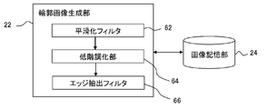
- FIG. 9 shows a detailed configuration of the contour image generation unit 22.
- the contour image generation unit 22 includes a smoothing filter 62, a gradation reduction unit 64, and an edge extraction filter 66.
- the contour image generation unit 22 reads the image frame of the input image stored in the image storage unit 24, smoothes it with the smoothing filter 62, lowers the gradation with the gradation reduction unit 64, and extracts the edge with the edge extraction filter 66. Are applied in this order to generate a contour image.
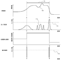
- FIG. 10 is a diagram for explaining a difference between a general edge extraction process and a contour image generation process in the present embodiment.
- the horizontal axis of the graph in the figure all represents the position of the image, that is, the arrangement of pixels, and the range is common.
- the uppermost graph represents the distribution of luminance values of the original image that is the input image.
- the figure shows a pixel row in which an image to be tracked exists in a region 110 indicated by an arrow, and a pixel A and a pixel B have a contour to be tracked.
- the change in the luminance value in the vicinity of the pixel A is gentler with respect to the position than the change in the luminance value in the vicinity of the pixel B.
- Such a situation can frequently occur when the tracking target and the background color are similar in the vicinity of the pixel A, or only the pixel A side is in the shade.
- the luminance value is not constant because the color is changed or the shadow is formed in the region 110 of the image to be tracked, and the luminance value varies like the unevenness 112.
- the edge When generating an edge image of an original image showing such a luminance value distribution, the edge is generally extracted by filtering with an edge extraction filter such as a Laplacian filter. At this time, a threshold value is set for the magnitude of the change of the luminance value with respect to the image plane, and a portion where a change exceeding the threshold value is seen is extracted as an edge.
- the second row of FIG. 10 shows a graph when the edge image is generated as described above. That is, the magnitude of the amount of change in luminance value as shown in the graph is calculated as an edge value, and a portion having an edge value exceeding a preset threshold value 116, that is, a pixel in the vicinity of the pixel B is extracted as an edge. .
- the vicinity of pixel A which is the other contour, is not extracted as an edge because its edge value is smaller than the threshold value 116.
- the threshold value 116 is set to a small value, but by doing so, a portion having a relatively large edge value due to the unevenness 112 of the luminance value that is not related to the contour. 114 is also extracted as an edge.
- candidate curves are set for the contour of the tracking target, and the likelihood is observed by matching with the actual contour to estimate the position of the tracking target. Therefore, if there is a portion that is not extracted from the contour line, or if many lines other than the contour are extracted, the tracking accuracy naturally decreases.
- the optimum value changes for each image, and depending on the image, it can be said that it is an optimum value in the first place. There can be situations where there is no value.
- the present embodiment it is possible to extract the “outline of an object” rather than “the edge in the image” by roughly capturing the object as a surface from detailed information such as lines and gradations in the image.
- a low gradation image in which the luminance value of the original image is reduced is generated.
- the luminance value of the original image is represented by three gradations for easy understanding.
- the luminance value of the area 110 where the tracking target exists discontinuously changes from the luminance value of the other area, and becomes information indicating the presence of the tracking target as the area. .
- the contour image generation unit 22 first smoothes the image frame of the input image by the smoothing filter 62.
- the smoothing filter 62 a general smoothing filter such as a Gaussian filter, a median filter, a simple averaging filter, or a low-pass filter can be used. This removes excess high-frequency components and makes it easier to grasp the surface of the object as a region.
- the gradation-lowering unit 64 generates a gradation-reduced image as described above.
- the gradation reduction unit 64 can be realized by a general bit shift operation, and divides luminance values at predetermined boundaries, and converts the luminance values in each division into one luminance value.
- the luminance value may be equally divided from the bottom, or a luminance value that makes the number of pixels uniform when the color histogram of the image frame is created and divided may be used as the boundary.
- a general posterization method may be used.
- the number of gradations of the low gradation image can be about 8 to 32 gradations, for example.
- the number of gradations of the low gradation image may be reset depending on the tracking target, background, image content, type, and the like.
- a low gradation image having various gradations is generated by using a test image similar to that at the time of actual tracking, and a gradation that can generate a contour image with the highest accuracy or that does not fail tracking is obtained.
- an edge extraction filter 66 is applied to the low gradation image obtained by the gradation reduction unit 64 to generate a contour image.
- a general edge extraction filter such as a Laplacian filter, a Sobel filter, or a Canny edge filter can be used. Thereby, a binary image having different values in the contour portion and other portions is obtained as the contour image.
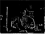
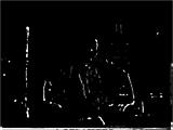
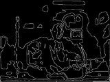
- FIG. 11 shows an example of an original image to be processed.
- 12 and 13 show the result of generating an edge image for the original image by a general edge image generation method.
- FIG. 12 shows a case where the threshold is low, and
- FIG. 13 shows a case where the threshold is high. It is an edge image.
- FIG. 12 in addition to the contour of the person who is the subject, many edges such as clothes patterns, wrinkles and facial parts are extracted, making it difficult to distinguish from the contour. Also, almost no edge is extracted from the shadowed portion on the left side of the person's head.
- the threshold value is increased, as shown in FIG. 13, the number of extracted edges decreases, and the outline is hardly extracted.
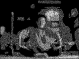
- FIG. 14 shows a low gradation image obtained by processing the original image shown in FIG. 11 by the smoothing filter 62 and the gradation reduction part 64 of the contour image generation unit 22 in the present embodiment.
- the low gradation image detailed information such as a clothing pattern as seen in the edge image of FIG. 12 is omitted, and the image is obtained by capturing the surface of a person or an object as an area.
- FIG. 15 shows a contour image generated by performing edge extraction processing on the low gradation image by the edge extraction filter 66.
- the outline of the person or object is represented by a continuous line, and in FIG. 12, the outline is also extracted from the left side of the person's head where no edge is extracted.
- the main purpose of this embodiment is to track the movement of a person or object in an image, priority is given to the presence of a contour line and information about the approximate position over detailed information of the image at the pixel level. By taking it out, it is possible to correctly detect the movement without mistaking or losing the tracking target.
- the gradation reduction process has the meaning of roughly dividing the image into regions based on the luminance value, and the boundaries of the regions generated thereby are regarded as contours, so that the lines are not interrupted in the middle and the search is easy. .
- a general edge image often appears with a certain width for pixels whose edge value exceeds a threshold value. This is because, as shown in the second stage of FIG. 10, the normal edge value changes approximately continuously with multiple gradations and reaches the peak with a certain width. Further, the lower the threshold value 116 is set so as to extract the edge reliably, the wider the extracted edge becomes.
- the gradation changes greatly even in adjacent pixels, and the edge value peaks in one pixel. Therefore, the extracted portion is a pixel unit, and the extraction result is linear. become. If the edge has a width, processing for thinning the edge is required to match the candidate curve. However, in the case of the contour line in this embodiment, this processing is not necessary, and tracking is performed at a high speed with a simpler configuration. Processing can be performed.
- the contour search process is divided for each knot. Assign to multiple processors and process in parallel. Since the contour search process is independent for each knot, allocation to processors and integration of results are easy. In addition, since the image data necessary for the contour search process for one knot is a limited area near the knot, the data size is small, and each processor copies the data to the local memory and performs the contour search process. Can be executed. Therefore, access to the contour image data can be performed at high speed, and the processing speed can be further improved.
- the number of processors required varies depending on the number of tracking targets, so if the number of tracking targets is smaller than the number of processors, the processing capacity of the device will be used up sufficiently. Disappear. Conversely, if the number of tracking targets is larger than the number of processors, some of the processing that could not be allocated will be executed later, eventually resulting in the possibility of surplus processing capacity.
- the image data size required for each search process varies greatly depending on the size of the tracking target, a memory capacity shortage or a data transfer time fluctuation may occur. Thus, if the processing time and the required memory size vary greatly depending on the contents of the input image, it may become an obstacle to determining the specifications of the apparatus, and the versatility will be poor.
- the search processing is divided for each knot to make the granularity of processing units finer and the number of processing units is increased, so that even if the tracking conditions such as the number of tracking people and the size of the tracking target change, There is little influence on processing time and required memory size, and it is easy to estimate those parameters. Therefore, the specification of the apparatus can be easily determined, and the tracking process can be performed in a suitable environment regardless of the contents of the input image. Similarly, parallel processing is possible with the same processing procedure regardless of the number of processors, and processing units of several thousand orders or more are generated per frame, so that they can be easily allocated to each processor. Since the processing unit is completed in a relatively short time, the scalability is high.
- the boundary between the surfaces can be extracted as a contour line.
- many extra edges other than the contour line are extracted depending on the threshold value for extraction, or the contour line is interrupted, which affects the tracking accuracy.
- the boundary between the surfaces is emphasized as described above, the allowable range of the threshold is wide, and the contour line can be easily extracted.
- the smoothing filter, low gradation part, and edge extraction filter used for contour image generation can all be processed by raster scan, and are independent processing for each line. Is possible. Further, since the contour image generated in the present embodiment appears in a line shape having a width corresponding to one pixel, it is not necessary to perform a thinning process for likelihood observation.
- Embodiment 2 In the first embodiment, knots and search areas are cut out in a one-to-one correspondence, and a contour search request is issued to each knot.
- the contour image is divided into a predetermined size in advance, and a contour search request is issued for each divided region.
- the configurations of the tracking device 14 and the observation unit 30 are the same as those shown in FIGS. 4 and 6, and the main processing procedure is the same as the procedure described in the first embodiment.
- description of the same processing as in the first embodiment will be omitted, and description will be made focusing on differences from the first embodiment.
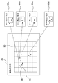
- FIG. 16 shows that the first processing unit 58a, the second processing unit 58b, the third processing unit 58c,...,
- the Nth processing unit 58n of the contour search unit are stored in the image storage unit 24 in the present embodiment.
- FIG. 6 schematically shows how the image data of the divided area is copied from the contour image to the respective local memories 60a, 60b, 60c,..., 60n.
- the contour image is divided regardless of the knot position.
- the contour image 90 is divided into six equal parts in the horizontal direction and five equal parts in the vertical direction. At this time, the number of divisions is determined in advance so that the size of each divided area 98 is equal to or less than the capacity of the local memories 60a, 60b, 60c,. Further, the division may not be performed equally. Coordinate information of such division patterns is stored in advance in the image storage unit 24 and the like, and the image cutout unit 50 reads out the information.
- the image cutout unit 50 determines which region the candidate curve knot 96 is included in for all candidate curves determined by the particles determined by the sampling unit 29. Then, a region 98 including the knot 96 is extracted, and a contour search processing request including information related to the region and coordinate information of all knots included in the region 98 is issued to the contour search task queue 52.
- the information related to the area to be included in the contour search request may be only the identification information. Get better.
- the Nth processing unit 58n of the contour search unit 56 read one contour search processing request from the contour search task queue 52, Based on the identification information of the designated area 98, the image data of the designated area 98 is copied from the contour image 90 stored in the image storage unit 24 to the subordinate local memory. Then, based on the coordinate information of the knot, the contour line closest to the knot is searched in the copied area. When a plurality of knots are included in the copied region, the contour line search is continuously performed for all knots, and the result of scoring for each knot is output to the likelihood acquisition unit 54. When the search is completed for all the knots included in the copied area, the next contour search processing request is read from the contour search task queue 52, and the same processing is repeated.
- the property is used to reduce the frequency of the area copy processing.
- the search processing for a part of the region copied at once is executed at a time regardless of which candidate curve knots, thereby increasing the processing efficiency.
- the likelihood acquisition unit 54 refers to the information that associates the knot information with the identification information of the candidate curve to which the knot belongs, so that each candidate curve is referred to. Likelihood can be obtained.
- the contour image is divided into a predetermined pattern, the contour search processing is divided for each divided region, assigned to a plurality of processors, and processed in parallel.
- Each processor copies the divided area to the local memory, and searches for the contour line in the copied area for all knots included in the area regardless of the candidate curve. Due to the nature of the particle filter, there are many situations where multiple candidate curves are close to each other and there are many knots in a limited area. The efficiency of the search can be improved. As a result, the processing can be advanced at a higher speed by the synergistic effect with the parallel processing and the use of the local memory described in the first embodiment.
- the contour image generation unit 22 includes a smoothing filter 62, a gradation reduction unit 64, and an edge extraction filter 66 as shown in FIG. 9, and generates a contour image by these processes.
- the contour image generation unit 22 may be a general edge extractor.
- the contour image generation unit 22 may include only the smoothing filter 62 and the edge extraction filter 66.
- the surface or background of the tracking target is not complicated, it is possible to generate an outline image with an edge extractor. Also in this case, the likelihood can be observed by performing an edge search using the generated edge image. High-speed tracking processing becomes possible by parallel processing.
- the contour image generation unit 22 may generate a contour image using a foreground extractor (not shown). For example, when the movement of a player is tracked using an image of a soccer game as an input image, the main background is the ground and the player wears a uniform, so each pixel value is limited. In such a case, the outline of the tracking target can be accurately extracted by a general foreground extraction process. A table associating them may be prepared so that the outline image generation unit 22 can determine which processing is performed according to the type of the input image. Or you may enable a user to change a setting.
- the contour image generation unit 22 may be provided in an image processing device other than the tracking device 14.
- an apparatus for automatically taking a photograph may be provided, and the image of the subject may be once captured and the contour image of the subject may be generated by the contour image generation unit 22.
- the position of the subject is calculated from the contour image, and the information is fed back to the camera orientation and position control device to automatically adjust the subject so that it appears in a desired position such as the center of the photograph.
- the present invention can be used for information processing apparatuses such as a visual tracking apparatus, a computer, a game machine, an imaging apparatus, and a moving image reproduction apparatus.
Abstract
Dans la figure 7, basée sur une distribution de probabilités existante d'une localisation de sujet à une trame précédente, des courbes de contours candidates d'une localisation de sujet au niveau de la trame actuelle sont déterminées au moyen de filtre particulaire. Afin de mettre en correspondance les courbes candidates avec l'image de contours d'une trame actuelle (90), le traitement de recherche d'une courbe de niveau dans le voisinage proche des courbes candidates est divisé pour chaque nœud (92) constituant la courbe candidate, de sorte qu'une pluralité d'unités de traitement effectuent le traitement divisé en parallèle. Des données d'images d'une zone de recherche (94) du nœud sujet de traitement (92) sont copiées à partir d'une image de contours (90) stockée au niveau d'une unité de mémoire d'images (24) à des mémoires locales (60a-60d) de chaque unité de traitement.
Priority Applications (2)
| Application Number | Priority Date | Filing Date | Title |
|---|---|---|---|
| US12/919,793 US8233661B2 (en) | 2008-03-14 | 2008-12-26 | Object tracking apparatus and object tracking method |
| EP08873286.2A EP2265023B1 (fr) | 2008-03-14 | 2008-12-26 | Dispositif de localisation de sujet et procédé de localisation de sujet |
Applications Claiming Priority (2)
| Application Number | Priority Date | Filing Date | Title |
|---|---|---|---|
| JP2008065198A JP5213486B2 (ja) | 2008-03-14 | 2008-03-14 | 対象物追跡装置および対象物追跡方法 |
| JP2008-065198 | 2008-03-14 |
Publications (1)
| Publication Number | Publication Date |
|---|---|
| WO2009113144A1 true WO2009113144A1 (fr) | 2009-09-17 |
Family
ID=41064827
Family Applications (1)
| Application Number | Title | Priority Date | Filing Date |
|---|---|---|---|
| PCT/JP2008/004015 WO2009113144A1 (fr) | 2008-03-14 | 2008-12-26 | Dispositif de localisation de sujet et procédé de localisation de sujet |
Country Status (4)
| Country | Link |
|---|---|
| US (1) | US8233661B2 (fr) |
| EP (1) | EP2265023B1 (fr) |
| JP (1) | JP5213486B2 (fr) |
| WO (1) | WO2009113144A1 (fr) |
Cited By (3)
| Publication number | Priority date | Publication date | Assignee | Title |
|---|---|---|---|---|
| CN105551063A (zh) * | 2016-01-29 | 2016-05-04 | 中国农业大学 | 一种用于跟踪视频中运动目标的方法以及装置 |
| CN112037254A (zh) * | 2020-08-11 | 2020-12-04 | 浙江大华技术股份有限公司 | 目标跟踪方法及相关装置 |
| CN114219832A (zh) * | 2021-11-29 | 2022-03-22 | 浙江大华技术股份有限公司 | 人脸跟踪方法、装置及计算机可读存储介质 |
Families Citing this family (38)
| Publication number | Priority date | Publication date | Assignee | Title |
|---|---|---|---|---|
| JP2011040993A (ja) * | 2009-08-11 | 2011-02-24 | Nikon Corp | 被写体追尾プログラム、およびカメラ |
| JP5528151B2 (ja) * | 2010-02-19 | 2014-06-25 | パナソニック株式会社 | 対象物追跡装置、対象物追跡方法、および対象物追跡プログラム |
| US8503539B2 (en) * | 2010-02-26 | 2013-08-06 | Bao Tran | High definition personal computer (PC) cam |
| CN102236899B (zh) * | 2010-05-07 | 2013-12-04 | 株式会社理光 | 物体检测方法和装置 |
| JP5762730B2 (ja) * | 2010-12-09 | 2015-08-12 | パナソニック株式会社 | 人検出装置および人検出方法 |
| KR101733116B1 (ko) * | 2010-12-10 | 2017-05-08 | 한국전자통신연구원 | 고속 스테레오 카메라를 이용한 구형 물체의 비행 정보 측정 시스템 및 방법 |
| JP4784709B1 (ja) * | 2011-03-10 | 2011-10-05 | オムロン株式会社 | 対象物追跡装置、対象物追跡方法、および制御プログラム |
| KR102026651B1 (ko) * | 2012-04-25 | 2019-09-30 | 삼성전자주식회사 | 입자 필터 프레임 워크를 이용한 강건한 객체 추적 방법 및 시스템 |
| US10009579B2 (en) | 2012-11-21 | 2018-06-26 | Pelco, Inc. | Method and system for counting people using depth sensor |
| US9367733B2 (en) * | 2012-11-21 | 2016-06-14 | Pelco, Inc. | Method and apparatus for detecting people by a surveillance system |
| US9639747B2 (en) | 2013-03-15 | 2017-05-02 | Pelco, Inc. | Online learning method for people detection and counting for retail stores |
| JP6295122B2 (ja) * | 2014-03-27 | 2018-03-14 | 株式会社メガチップス | 状態推定装置、プログラムおよび集積回路 |
| US9420331B2 (en) | 2014-07-07 | 2016-08-16 | Google Inc. | Method and system for categorizing detected motion events |
| US9501915B1 (en) | 2014-07-07 | 2016-11-22 | Google Inc. | Systems and methods for analyzing a video stream |
| US10140827B2 (en) | 2014-07-07 | 2018-11-27 | Google Llc | Method and system for processing motion event notifications |
| US10127783B2 (en) | 2014-07-07 | 2018-11-13 | Google Llc | Method and device for processing motion events |
| US9449229B1 (en) | 2014-07-07 | 2016-09-20 | Google Inc. | Systems and methods for categorizing motion event candidates |
| US9213903B1 (en) | 2014-07-07 | 2015-12-15 | Google Inc. | Method and system for cluster-based video monitoring and event categorization |
| USD782495S1 (en) | 2014-10-07 | 2017-03-28 | Google Inc. | Display screen or portion thereof with graphical user interface |
| US10133927B2 (en) * | 2014-11-14 | 2018-11-20 | Sony Corporation | Method and system for processing video content |
| US9715622B2 (en) * | 2014-12-30 | 2017-07-25 | Cognizant Technology Solutions India Pvt. Ltd. | System and method for predicting neurological disorders |
| KR101635973B1 (ko) * | 2015-04-23 | 2016-07-04 | 국방과학연구소 | Ir 영상 추적에서 파티클 필터를 이용한 기억 추적 성능 향상 방법 및 장치 |
| US9361011B1 (en) | 2015-06-14 | 2016-06-07 | Google Inc. | Methods and systems for presenting multiple live video feeds in a user interface |
| US9449254B1 (en) | 2015-08-04 | 2016-09-20 | Adobe Systems Incorporated | Adaptive environment targeting |
| US10506237B1 (en) | 2016-05-27 | 2019-12-10 | Google Llc | Methods and devices for dynamic adaptation of encoding bitrate for video streaming |
| US10380429B2 (en) | 2016-07-11 | 2019-08-13 | Google Llc | Methods and systems for person detection in a video feed |
| US10346715B2 (en) * | 2017-04-07 | 2019-07-09 | GM Global Technology Operations LLC | Camera misalignment determination methods and systems |
| US11783010B2 (en) | 2017-05-30 | 2023-10-10 | Google Llc | Systems and methods of person recognition in video streams |
| CN107426497A (zh) * | 2017-06-15 | 2017-12-01 | 深圳天珑无线科技有限公司 | 一种记录影像的方法、装置及计算机可读存储介质 |
| US10664688B2 (en) | 2017-09-20 | 2020-05-26 | Google Llc | Systems and methods of detecting and responding to a visitor to a smart home environment |
| JP6412998B1 (ja) * | 2017-09-29 | 2018-10-24 | 株式会社Qoncept | 動体追跡装置、動体追跡方法、動体追跡プログラム |
| CN109819178B (zh) * | 2017-11-21 | 2022-07-08 | 虹软科技股份有限公司 | 一种用于帧处理的方法和装置 |
| US11494922B2 (en) * | 2018-03-23 | 2022-11-08 | Nec Corporation | Object tracking device, object tracking method, and object tracking program |
| EP3906528A1 (fr) * | 2018-12-31 | 2021-11-10 | I-Deal S.r.l. | Dispositif portable d'acquisition de données anthropométriques et procédé de collecte de données anthropométriques |
| CN111107319B (zh) * | 2019-12-25 | 2021-05-28 | 眸芯科技(上海)有限公司 | 基于区域摄像头的目标追踪方法、装置及系统 |
| CN111402288A (zh) * | 2020-03-26 | 2020-07-10 | 杭州博雅鸿图视频技术有限公司 | 目标检测跟踪方法及装置 |
| CN114313883B (zh) * | 2022-02-08 | 2024-03-12 | 深圳市铁越电气有限公司 | 基于图像处理技术的皮带跑偏自动检测方法及系统 |
| CN116469041B (zh) * | 2023-06-20 | 2023-09-19 | 成都理工大学工程技术学院 | 一种目标对象的运动轨迹预测方法、系统及设备 |
Citations (4)
| Publication number | Priority date | Publication date | Assignee | Title |
|---|---|---|---|---|
| JPH05216988A (ja) * | 1992-02-04 | 1993-08-27 | Hitachi Ltd | テンプレート演算処理方法および装置 |
| JPH11167455A (ja) * | 1997-12-05 | 1999-06-22 | Fujitsu Ltd | 手形状認識装置及び単色物体形状認識装置 |
| JP2007328746A (ja) * | 2006-06-09 | 2007-12-20 | Sony Computer Entertainment Inc | 対象物追跡装置および対象物追跡方法 |
| JP2007328747A (ja) * | 2006-06-09 | 2007-12-20 | Sony Computer Entertainment Inc | 特徴点探索装置、画像解析装置、および最近傍特徴点検出方法 |
Family Cites Families (3)
| Publication number | Priority date | Publication date | Assignee | Title |
|---|---|---|---|---|
| JP3288086B2 (ja) * | 1992-10-26 | 2002-06-04 | 株式会社東芝 | 動物体抽出装置 |
| JP2006268097A (ja) * | 2005-03-22 | 2006-10-05 | Nissan Motor Co Ltd | 車載物体検出装置、および物体検出方法 |
| FR2885719B1 (fr) * | 2005-05-10 | 2007-12-07 | Thomson Licensing Sa | Procede et dispositif de suivi d'objets dans une sequence d'images |
-
2008
- 2008-03-14 JP JP2008065198A patent/JP5213486B2/ja active Active
- 2008-12-26 WO PCT/JP2008/004015 patent/WO2009113144A1/fr active Application Filing
- 2008-12-26 US US12/919,793 patent/US8233661B2/en active Active
- 2008-12-26 EP EP08873286.2A patent/EP2265023B1/fr active Active
Patent Citations (4)
| Publication number | Priority date | Publication date | Assignee | Title |
|---|---|---|---|---|
| JPH05216988A (ja) * | 1992-02-04 | 1993-08-27 | Hitachi Ltd | テンプレート演算処理方法および装置 |
| JPH11167455A (ja) * | 1997-12-05 | 1999-06-22 | Fujitsu Ltd | 手形状認識装置及び単色物体形状認識装置 |
| JP2007328746A (ja) * | 2006-06-09 | 2007-12-20 | Sony Computer Entertainment Inc | 対象物追跡装置および対象物追跡方法 |
| JP2007328747A (ja) * | 2006-06-09 | 2007-12-20 | Sony Computer Entertainment Inc | 特徴点探索装置、画像解析装置、および最近傍特徴点検出方法 |
Non-Patent Citations (3)
| Title |
|---|
| MICHAEL ISARD; ANDREW BLAKE: "CONDENSATION - conditional density propagation for visual tracking", INT. J. COMPUTER VISION, vol. 29, no. 1, 1998, pages 5 - 28, XP002329561, DOI: doi:10.1023/A:1008078328650 |
| MICHAEL ISARD; ANDREW BLAKE: "Contour tracking by stochastic propagation of conditional density", PROC. EUROPEAN CONF. ON COMPUTER VISION, vol. 1, 1996, pages 343 - 356, XP019190190 |
| MICHAEL ISARD; ANDREW BLAKE: "ICondensation: Unifying low-level and high-level tracking in a stochastic framework", PROC 5TH EUROPEAN CONF. COMPUTER VISION, 1998 |
Cited By (4)
| Publication number | Priority date | Publication date | Assignee | Title |
|---|---|---|---|---|
| CN105551063A (zh) * | 2016-01-29 | 2016-05-04 | 中国农业大学 | 一种用于跟踪视频中运动目标的方法以及装置 |
| CN105551063B (zh) * | 2016-01-29 | 2018-04-17 | 中国农业大学 | 一种用于跟踪视频中运动目标的方法以及装置 |
| CN112037254A (zh) * | 2020-08-11 | 2020-12-04 | 浙江大华技术股份有限公司 | 目标跟踪方法及相关装置 |
| CN114219832A (zh) * | 2021-11-29 | 2022-03-22 | 浙江大华技术股份有限公司 | 人脸跟踪方法、装置及计算机可读存储介质 |
Also Published As
| Publication number | Publication date |
|---|---|
| US20110058708A1 (en) | 2011-03-10 |
| JP2009224924A (ja) | 2009-10-01 |
| EP2265023A4 (fr) | 2016-05-25 |
| EP2265023B1 (fr) | 2019-05-29 |
| US8233661B2 (en) | 2012-07-31 |
| EP2265023A1 (fr) | 2010-12-22 |
| JP5213486B2 (ja) | 2013-06-19 |
Similar Documents
| Publication | Publication Date | Title |
|---|---|---|
| JP5213486B2 (ja) | 対象物追跡装置および対象物追跡方法 | |
| JP4756660B2 (ja) | 画像処理装置および画像処理方法 | |
| JP6030617B2 (ja) | 画像処理装置および画像処理方法 | |
| JP5520463B2 (ja) | 画像処理装置、対象物追跡装置および画像処理方法 | |
| JP4766495B2 (ja) | 対象物追跡装置および対象物追跡方法 | |
| US6658136B1 (en) | System and process for locating and tracking a person or object in a scene using a series of range images | |
| EP1969559B1 (fr) | Detection des contours lors de la segmentation de sequences video | |
| WO2010073432A1 (fr) | Dispositif de traitement d'image et procédé de traitement d'image | |
| JP4597391B2 (ja) | 顔領域検出装置およびその方法並びにコンピュータ読み取り可能な記録媒体 | |
| EP1969561A1 (fr) | Segmentation de sequences video | |
| JP2010152556A (ja) | 画像処理装置および画像処理方法 | |
| Langmann et al. | Multi-modal background subtraction using gaussian mixture models | |
| Rao et al. | Object tracking system using approximate median filter, Kalman filter and dynamic template matching | |
| KR20170015299A (ko) | 배경 추적을 통한 오브젝트 추적 및 분할을 위한 방법 및 장치 | |
| JP2010057105A (ja) | オブジェクトの3次元追跡方法およびシステム | |
| JP5468773B2 (ja) | 画像処理装置および画像処理方法 | |
| JP4449483B2 (ja) | 画像解析装置、および画像解析方法、並びにコンピュータ・プログラム | |
| JP2016081252A (ja) | 画像処理装置および画像処理方法 | |
| EP3956864A1 (fr) | Procédé de mise en oeuvre de réalité augmentée | |
| JP2009003615A (ja) | 注目領域抽出方法、注目領域抽出装置、コンピュータプログラム、及び、記録媒体 | |
| Rashi et al. | Analysis of different image processing strategies | |
| Cinque et al. | Real-time foreground segmentation with Kinect sensor | |
| JP7341712B2 (ja) | 画像処理装置、画像処理方法、撮像装置、およびプログラム | |
| JP2005071125A (ja) | 被写体検出装置、被写体検出方法、被写体データ選定プログラムおよび被写体位置検出プログラム | |
| Cinque et al. | Automatic selection of regions of interest in a video by a depth-color image matting |
Legal Events
| Date | Code | Title | Description |
|---|---|---|---|
| 121 | Ep: the epo has been informed by wipo that ep was designated in this application |
Ref document number: 08873286 Country of ref document: EP Kind code of ref document: A1 |
|
| NENP | Non-entry into the national phase |
Ref country code: DE |
|
| WWE | Wipo information: entry into national phase |
Ref document number: 2008873286 Country of ref document: EP |
|
| WWE | Wipo information: entry into national phase |
Ref document number: 12919793 Country of ref document: US |