WO2009113144A1 - 対象物追跡装置および対象物追跡方法 - Google Patents
対象物追跡装置および対象物追跡方法 Download PDFInfo
- Publication number
- WO2009113144A1 WO2009113144A1 PCT/JP2008/004015 JP2008004015W WO2009113144A1 WO 2009113144 A1 WO2009113144 A1 WO 2009113144A1 JP 2008004015 W JP2008004015 W JP 2008004015W WO 2009113144 A1 WO2009113144 A1 WO 2009113144A1
- Authority
- WO
- WIPO (PCT)
- Prior art keywords
- image
- contour
- search
- processing
- edge
- Prior art date
Links
Images


Classifications
-
- G—PHYSICS
- G06—COMPUTING; CALCULATING OR COUNTING
- G06T—IMAGE DATA PROCESSING OR GENERATION, IN GENERAL
- G06T7/00—Image analysis
- G06T7/20—Analysis of motion
- G06T7/277—Analysis of motion involving stochastic approaches, e.g. using Kalman filters
-
- G—PHYSICS
- G06—COMPUTING; CALCULATING OR COUNTING
- G06T—IMAGE DATA PROCESSING OR GENERATION, IN GENERAL
- G06T7/00—Image analysis
- G06T7/20—Analysis of motion
- G06T7/246—Analysis of motion using feature-based methods, e.g. the tracking of corners or segments
- G06T7/251—Analysis of motion using feature-based methods, e.g. the tracking of corners or segments involving models
-
- G—PHYSICS
- G06—COMPUTING; CALCULATING OR COUNTING
- G06T—IMAGE DATA PROCESSING OR GENERATION, IN GENERAL
- G06T2207/00—Indexing scheme for image analysis or image enhancement
- G06T2207/10—Image acquisition modality
- G06T2207/10016—Video; Image sequence
Definitions
- the present invention relates to information processing technology, and more particularly, to an object tracking device for tracking an object in an input image and an object tracking method executed there.
- Visual tracking has a wide range of applications such as computer vision, especially visual surveillance in the security field, analysis / classification, editing of recorded video in the AV field, man-machine interface, and human-to-human interface, that is, video conferencing and videophone. Expected. Therefore, many studies have been made for the purpose of improving tracking accuracy and processing efficiency. In particular, much research has been done on the application of particle filters, which are attracting attention as a time-series analysis method for signals with added non-Gaussian noise that cannot be handled by Kalman filters, especially for the Condensation (Conditional (Density Propagation) algorithm. Is famous (see, for example, Non-Patent Document 1 to Non-Patent Document 3).
- the particle filter is an approximate calculation method of the Bayes filter, and expresses a target probability distribution by introducing a finite number of particles as tracking candidates, and performs time series estimation and prediction using the target probability distribution.
- the Condensation algorithm uses a particle filter to estimate the temporal change of the probability distribution for the shape of the tracking target. Specifically, the contour line of a candidate having the same shape as the tracking target is represented by one particle, and the existence probability distribution in the target parameter space is calculated by calculating the likelihood of the parameter transition by the motion model and the transition result by the observation. Estimate sequentially. Contour tracking by stochastic propagation of conditional density, Michael Isard and Andrew Blake, Proc.European Conf. On Computer Vision, vol.
- the present invention has been made in view of such problems, and it is an object of the present invention to provide a visual tracking technique with high scalability, in which the efficiency of tracking processing is not easily affected by changes in the tracking target.
- An aspect of the present invention relates to an object tracking device.
- This object tracking device estimates the presence of an object in a first image frame out of a first image frame and a second image frame included in an image stream constituting moving image data obtained by capturing an object to be tracked. Based on the probability distribution, the candidate contour determination unit for determining the candidate contour of the object in the second image frame, the candidate contour determined by the candidate contour determination unit, and the edge image of the second image frame are matched to obtain a candidate An observation unit for observing the likelihood of the contour, and a result acquisition unit for estimating the existence probability distribution of the object in the second image frame based on the likelihood observed by the observation unit.
- a plurality of search units that execute the process of searching for the nearest edge from the knots constituting the curve of the curve in parallel for each knot, and the results searched by the search unit are integrated for each candidate contour Characterized by comprising the likelihood acquisition unit for obtaining the likelihood, the.
- first image frame and the “second image frame” may be adjacent image frames in the image stream or may be image frames positioned apart from each other.
- first image frame is an image frame temporally prior to the “second image frame”. Is not limited to this.
- the “existence probability distribution” may be an existence probability distribution with respect to the position coordinates in the image frame of the object, and a parameter representing any of the attributes of the object such as shape, color, size, or a combination thereof. It may be an existence probability distribution for the extended space.
- a “candidate contour” is a graphic representing a candidate for a contour line of a part or the whole of an object.
- the “likelihood” is a degree representing how close the candidate contour is to the object, for example, a numerical value indicating the degree of overlap with the object, the distance from the object, and the like.
- Another aspect of the present invention relates to an object tracking method.
- This object tracking method estimates the presence of an object in the first image frame out of the first image frame and the second image frame included in the image stream constituting the moving image data obtained by capturing the object to be tracked. Determining a candidate contour of the object in the second image frame based on the probability distribution, generating an edge image of the second image frame and storing it in a memory, and a portion of the edge image stored in the memory.
- the process of detecting the nearest edge from the knots that make up the curve of the candidate contour by reading and searching the image data of the region and integrating the result of edge detection with the step of executing in parallel for each knot Obtaining likelihood for each candidate contour, and estimating the existence probability distribution of the object in the second image frame.
- a high-speed and highly scalable visual tracking technique can be realized.
- FIG. 1 is a diagram illustrating a configuration example of a visual tracking system in Embodiment 1.
- FIG. It is a figure which shows the structure of the tracking apparatus in Embodiment 1 in detail.
- 3 is a flowchart showing a procedure of tracking processing in the first embodiment.
- FIG. 3 is a diagram illustrating the configuration of an observation unit in the first embodiment in more detail.
- FIG. 6 is a diagram schematically showing a state in which image data of a region cut out from a contour image stored in an image storage unit in the first embodiment is copied to each local memory.
- FIG. 6 is a diagram schematically illustrating a process transition when the first processing unit, the second processing unit,..., The Nth processing unit of the contour search unit perform the contour search processing in the first embodiment.
- 3 is a diagram illustrating a detailed configuration of a contour image generation unit according to Embodiment 1.
- FIG. It is a figure for demonstrating the difference of a general edge extraction process and the outline image generation process in this Embodiment. It is a figure which shows the example of the original image which is a process target. It is a figure which shows the edge image produced
- FIG. 12 is a diagram showing a gradation-reduced image obtained as an intermediate image when the contour image generation process of the present embodiment is performed on the original image shown in FIG. 11 in the first embodiment. It is a figure which shows the outline image produced
- FIG. 10 is a diagram schematically showing a state in which image data of a divided region is copied from each contour image stored in an image storage unit to each local memory in the second embodiment.
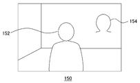
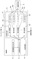
- FIG. 1 is a diagram for explaining a visual tracking method when a person is a tracking target.
- the person image 150 is one of the image frames constituting the image stream of the moving image generated by the moving image or the computer graphics that is actually captured, and the person 152 to be tracked is captured.
- an ⁇ -shaped curve 154 that approximates the shape of the head contour of the person 152 is described in a known expression.
- the person image 150 including the person 152 is subjected to edge extraction processing to obtain an edge image. Then, by changing the shape and position while changing the parameter defining the curve 154 and searching for an edge in the vicinity thereof, the value of the parameter estimated to be the best match with the head contour of the person 152 is specified.
- the tracking of the person 152 progresses by repeating the above processing for each frame.
- the edge generally refers to a portion having an abrupt change in image density or color.
- a probability distribution prediction technique using a particle filter is introduced.
- the number of samplings of the curve 154 is increased or decreased according to the probability distribution of the object in the parameter space in the immediately preceding frame, and the tracking candidates are narrowed down.
- Non-Patent Document 3 (ICondensation: Unifying low-level and high-level tracking in a stochastic framework, Michael Isard and Andrew Blake, Proc 5th European Conf. Computer Vision, 1998).
- the description will be focused on the points according to the present embodiment.
- the ⁇ -shaped curve 154 is described as a B-spline curve.
- the B-spline curve is defined by n control point sequences (Q0,..., Qn) and knot sequences (s0,..., Sn). These parameters are set in advance so as to form a basic curve shape, in this case, an ⁇ -shaped curve.
- the curve obtained by the setting at this time is hereinafter referred to as template Q0.
- the template Q0 has an ⁇ shape, but the shape is changed depending on the tracking target. That is, if the tracking target is a ball, the shape is circular, and if the tracking target is a palm, the shape is a hand.
- a shape space vector x is prepared as a conversion parameter for changing the shape of the template.
- the shape space vector x is composed of the following six parameters.
- (shift x , shift y ) is a translation amount in the (x, y) direction
- (extend x , extend y ) is a magnification
- ⁇ is a rotation angle.
- the template can be translated, stretched and rotated by appropriately changing the six parameters constituting the shape space vector x, and the shape and position of the candidate curve Q can be changed variously depending on the combination. it can.
- a plurality of candidate curves expressed by changing the parameters of the template Q 0 such as the interval between the control point sequence and the knot sequence and the six parameters constituting the shape space vector x are persons in the vicinity of each knot. Search for 152 edges. Thereafter, the likelihood density distribution in the six-dimensional space spanned by the six parameters constituting the shape space vector x is estimated by obtaining the likelihood of each candidate curve from the distance to the edge or the like.
- FIG. 2 is a diagram for explaining a probability density distribution estimation method using a particle filter.
- the change of a certain parameter x1 is shown on the horizontal axis, but actually the same processing is performed in the 6-dimensional space. Is called.
- the image frame whose probability density distribution is to be estimated is the image frame at time t.
- a particle is a materialization of the value of the parameter x1 to be sampled and the sampling density. For example, in the region of the parameter x1, where the probability density was high at time t-1, sampling is performed by increasing the particle density. In the range where the probability density is low, sampling is not performed by reducing the number of particles. Thereby, for example, many candidate curves are generated near the edge of the person 152, and matching is performed efficiently.
- the predetermined motion model is, for example, a Gaussian motion model, an autoregressive prediction motion model, or the like.
- the former is a model in which the probability density at time t is Gaussian distributed around each probability density at time t-1.
- the latter is a method that assumes a second-order or higher-order autoregressive prediction model acquired from sample data. For example, it is estimated from a change in past parameters that a person 152 is moving at a certain speed. In the example of FIG. 2, the motion in the positive direction of the parameter x1 is estimated by the autoregressive prediction type motion model, and each particle is changed in that way.
- the likelihood of each candidate curve is obtained by searching for the edge of the person 152 in the vicinity of the candidate curve determined by each particle using the edge image at time t, and the probability density distribution at time t is obtained.
- Estimate (S16) As described above, the probability density distribution at this time is a discrete representation of the true probability density distribution 400 as shown in S16. Thereafter, by repeating this, the probability density distribution at each time is represented in the parameter space. For example, if the probability density distribution is unimodal, that is, if the tracked object is unique, the final parameter is the weighted sum of each parameter value using the obtained probability density. Thus, the contour curve closest to the tracking target is obtained.
- the probability density distribution p (x t i ) at time t estimated in S16 is calculated as follows.
- i is a number uniquely given to a particle
- x t i , u t ⁇ 1 ) is a predetermined motion model
- x t i ) is a likelihood.
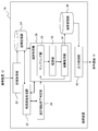
- FIG. 3 shows a configuration example of the visual tracking system in the present embodiment.
- the visual tracking system 10 includes an imaging device 12 that images the tracking target 18, a tracking device 14 that performs tracking processing, and a display device 16 that outputs image data captured by the imaging device 12 and tracking result data.
- the tracking target 18 may vary depending on the purpose of use of the visual tracking system 10 such as a person, an object, or a part thereof, but in the following description, it is assumed that the person is a person as in the above example.
- connection between the tracking device 14 and the imaging device 12 or the display device 16 may be wired or wireless, and may be via various networks. Alternatively, any two or all of the imaging device 12, the tracking device 14, and the display device 16 may be combined and integrally provided. Depending on the usage environment, the imaging device 12 and the display device 16 may not be connected to the tracking device 14 at the same time.
- the imaging device 12 acquires data of an image including the tracking target 18 or an image of a certain place regardless of the presence or absence of the tracking target 18 at a predetermined frame rate.
- the acquired image data is input to the tracking device 14, and the tracking processing of the tracking target 18 is performed.
- the processing result is output as output data to the display device 16 under the control of the tracking device 14.
- the tracking device 14 may also serve as a computer that performs another function, and may implement various functions by using data obtained as a result of the tracking process, that is, position information and shape information of the tracking target 18. .
- FIG. 4 shows the configuration of the tracking device 14 in the present embodiment in detail.
- the tracking device 14 includes an image acquisition unit 20 that acquires input image data input from the imaging device 12, an image storage unit 24 that stores the input image data and the contour image data, and a contour image that generates a contour image from the input image data.
- a generation unit 22 a tracking start / end determination unit 28 that determines the start and end of tracking, a tracking processing unit 26 that performs tracking processing using a particle filter, a result storage unit 36 that stores final tracking result data, and a tracking result
- the output control part 40 which controls the output to the display apparatus 16 is included.
- each element described as a functional block for performing various processes can be configured with a CPU, a memory, and other LSIs in terms of hardware, and a program for performing image processing in terms of software. It is realized by. Therefore, it is understood by those skilled in the art that these functional blocks can be realized in various forms by hardware only, software only, or a combination thereof, and is not limited to any one.
- the contour image generation unit 22 extracts the contour line to be tracked from the image frame of the input image, and generates a contour image.
- the contour image is stored in the image storage unit 24 and later used in the observation of the candidate curve in the observation unit 30 of the tracking processing unit 26.
- “contour lines” are treated as “edges” in an edge image, and thus, with the conventional technique, likelihood observation using an “edge image” has been performed.
- edge extraction filters many edges are extracted in addition to the contour line of an object depending on the input image, so it is considered that likelihood observation cannot be performed accurately due to matching with edges other than the contour line. It is done. Further, if the threshold value for edge extraction is set high and the number of edges is reduced, the contour line is cut off, and there is a possibility that the likelihood observation is not accurately performed.
- the contour image generation unit 22 generates not only a general “edge image” but also an image that can accurately perform likelihood observation by focusing on the “contour” of an object in the input image. To do. Although a specific method will be described later, in the following description, an image generated by the contour image generation unit 22 is distinguished from a general “edge image” as a “contour image”. Further, the contour image generation unit 22 may be mounted with a foreground extractor (not shown) using a background difference. Then, the contour of the tracking target may be efficiently extracted by extracting the foreground including the tracking target from the input image as preprocessing of the contour image generation processing.
- the tracking start / end determining unit 28 evaluates, for example, the contour line or the foreground shape obtained by the contour image generating unit 22 and determines whether to start or end tracking according to a predetermined condition.
- end may include a temporary stop of tracking by occlusion or the like. Tracking starts when the tracking target appears within the viewing angle of the imaging device or when it appears from behind the object, etc.When the tracking target leaves the viewing angle of the imaging device or enters the shadow, etc. To finish. When it is determined that the tracking is to be started, the tracking processing unit 26 is notified to that effect and the tracking process is started.
- the tracking processing unit 26 includes a sampling unit 29, an observation unit 30, and a result acquisition unit 34.
- the sampling unit 29 performs particle generation and extinction processing based on the probability density distribution estimated for the previous image frame at time t-1. Then, a predetermined motion model is applied to all the particles to cause the particles to transition on the parameter space. Thereby, a plurality of candidate curves in the image frame at time t are determined.
- the sampling unit 29 starts the process when receiving a signal indicating the start of tracking from the tracking start / end determining unit 28, and ends the process when receiving a signal indicating the end of tracking.
- the observation unit 30 observes the likelihood of the candidate curve defined by each particle generated, disappeared, and transitioned by the sampling unit. For example, when the candidate curve defined by each particle is expressed by a B-spline curve, for each knot of the B-spline curve, the nearest contour line is searched for in the contour image generated by the contour image generation unit 22 to obtain the distance. To score the knots according to a predetermined rule. Then, the likelihood of the candidate curve is obtained based on the scores of all knots constituting the candidate curve. The observation unit 30 executes this search process in parallel using a plurality of processor units.
- a processing unit obtained by dividing the contour search processing for each knot is used as one processing unit, and a plurality of processor units perform parallel processing.
- Each processor unit copies only the image data of a part of the contour image including the knot and the search region to the subordinate local memory in order to search for the contour line closest to one knot. .
- the number of processing units of (number of particles) ⁇ (number of knots constituting candidate curve) is processed in a short time for each tracking target.
- the score of each knot acquired in parallel by each processor unit is integrated for each candidate curve, and the likelihood is calculated. Conventional techniques can be used for scoring and likelihood calculation.
- the result acquisition unit 34 calculates a probability density distribution p (x t i ) as shown in Expression 3 based on the likelihood observed by the observation unit 30, and tracks the curve data obtained by the weighted average parameter.
- the result is calculated and stored in the result storage unit 36.
- the data is returned to the sampling unit 29 for use in the tracking process at the next time t + 1.
- the data stored in the result storage unit 36 may be the value of each parameter that has been weighted and averaged, and may be any of an image composed only of a curve determined by that, or image data formed by combining a curve and an input image But you can.
- the result acquisition unit 34 may further track each tracking target using a template prepared for each, and combine the tracking results into one tracking result. Further, a case where a plurality of tracking targets overlap is detected based on the tracking result, and the tracking target hidden behind is taken out of the tracking processing target at a predetermined timing. As a result, even if the observation likelihood is temporarily lowered due to the tracking target moving behind another tracking target, it is possible to avoid outputting an inappropriate tracking result.
- the result storage unit 36 stores, for example, moving image data including the tracking result.
- the result storage unit 36 stores, for example, moving image data including the tracking result.
- the display device 16 by outputting the moving image data to the display device 16 under the control of the output control unit 40, it is possible to display how the curve of the template moves in the same manner as the movement of the tracking target.
- processing such as output to another arithmetic module may be appropriately performed according to the purpose of tracking.
- the imaging device 12 captures a place to be captured at a predetermined frame rate.
- the captured image is input as input image data to the image acquisition unit 20 of the tracking device 14 and stored in the image storage unit 24. In such a state, the following tracking process is performed.
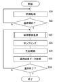
- FIG. 5 is a flowchart showing the procedure of the tracking process in the present embodiment.
- the tracking target is a person
- an ⁇ -type template is prepared for the tracking device 14 as described above.
- the template expression method is not limited to the B-spline curve, but may be any description format that can express a desired curve.
- the template shape deformation method may be appropriately selected from methods that can be adapted to the description format and that can be flexibly deformed as described above by changing several types of parameters.
- the tracking start / end determination unit 28 reads the input image data stored in the image storage unit 24 for each frame and determines whether or not to start tracking (S20, S22). For example, when an object having a predetermined size and shape that can be estimated as a person appears as a foreground extracted from an image frame, it is determined to start tracking.
- the size and shape of the foreground used as a judgment criterion are determined in advance logically or experimentally.
- Foreground extraction processing may use a foreground extractor (not shown) mounted on the contour image generation unit 22. In this case, the tracking start / end determining unit 28 requests the contour image generating unit 22 for foreground extraction processing.
- the tracking start / end determination unit 28 may be equipped with a foreground extractor.
- the tracking processing unit 26 starts the tracking process.
- the sampling unit 29 requests the contour image generation unit 22 for a contour image generation process
- the sampling unit 29 may also request a contour image generation process for the subsequent frame, and the contour image generation unit 22 may sequentially perform the process.
- the sampling unit 29 performs sampling by arranging particles evenly in a predetermined region of the parameter space, for example, and the observation unit 30 observes the likelihood by matching the candidate curve defined by each particle and the contour image, and the result
- the acquisition unit 34 calculates the initial value p (x 0 i ) of the rate density distribution using Equation 3 (S28, S30, S32).
- the sampling unit 29 generates a number of particles corresponding to the generated initial value p (x 0 i ) of the probability density distribution on the parameter space, and performs sampling by transitioning the particles based on a predetermined motion model ( S28).
- the number of particles to be generated is controlled in consideration of the processing load based on the amount of computation resources of the tracking device 14 and the required result output speed.
- a motion model that can be obtained with high tracking accuracy from a Gaussian motion model, an autoregressive motion model, or the like is determined in advance according to the type of tracking target.
- the observation unit 30 observes the likelihood p (y t
- search processing is allocated to a plurality of processors for each knot. Details will be described later.
- the tracking start / end determining unit 28 determines whether to continue or end the tracking process (S34). For example, the tracking end is determined when a target having a predetermined size and shape that can be estimated as a person does not appear as a foreground for a predetermined time. Alternatively, the end of tracking is determined when the occlusion state continues for a predetermined time, such as when a tracking target in real space moves behind another tracking target. The occlusion state may be estimated from past tracking processing results, or may be detected by a distance measurement system (not shown). Further, a situation in which the tracking target deviates from the angle of view of the imaging device 12 continues for a predetermined time is also detected by a method similar to occlusion and the tracking end is determined.
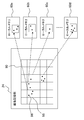
- FIG. 6 shows the configuration of the observation unit 30 in more detail.
- the observation unit 30 includes a contour image cutout unit 50, a contour search task queue 52, a contour search unit 56, and a likelihood acquisition unit 54.
- the contour image cutout unit 50 cuts out a region corresponding to each knot from the contour image based on the knot coordinates of the curve representing the candidate curve.
- the area corresponding to each knot is an area including the knot and a search area for the knot. It may be equal to the search area, and is also referred to as “search area” in the following description.
- a processing request for contour search including coordinate information of knots and information related to the corresponding region is issued. The issued processing request is added to the processing queue in the contour search task queue 52.
- the contour search unit 56 includes N processing units of a first processing unit 58a, a second processing unit 58b, a third processing unit 58c,..., An Nth processing unit 58n, and local memories 60a and 60b connected to the N processing units. , 60c, ..., 60n.
- Each processing unit sequentially reads out contour search processing requests from the contour search task queue 52 and executes the contour search processing for the requested knots. Specifically, the image data of the area specified by the processing request is copied from the contour image stored in the image storage unit 24 to the subordinate local memory. Based on the coordinates of the designated knot, the contour line closest to the knot is searched in the area copied to the local memory and scored according to a predetermined rule.
- a generally used edge search technique can be used for contour search.
- the search area can be determined by the selected search method and the accuracy required for matching.
- the N-th processing unit 58n executes one processing request, the obtained score is output to the likelihood acquisition unit 54. To do. Then, the next contour search processing request is read from the contour search task queue 52, and the same processing is repeated.
- the likelihood acquisition unit 54 integrates the scores of the knots respectively input from the first processing unit 58a, the second processing unit 58b, the third processing unit 58c, ..., the N-th processing unit 58n of the contour search unit.
- the likelihood for each candidate curve is calculated.
- the scores of all knots constituting the candidate curve are collected and summed, an average value is calculated, or substituted into a predetermined conversion formula.
- the scores for the knots are output one after another from each processing unit of the contour search unit 56, and information that associates the identification information of the knots with the identification information of the candidate curve to which the knot belongs is shared in the observation unit 30.
- the result can be integrated for each candidate curve by storing it and including necessary identification information when processing requests and scores are output.
- FIG. 6 schematically shows how the image data of the designated area is copied from the contour image to the local memories 60a, 60b, 60c,.
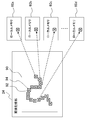
- the image storage unit 24 stores a contour image 90 generated by the contour image generation unit 22.
- the coordinates of the knots 92 of the candidate curve are determined by the particles determined by the sampling unit 29.
- the contour image cutout unit 50 When the contour image cutout unit 50 acquires the coordinates of the knots 92, the contour image cutout unit 50 cuts out the search area 94 of the knots for each knot.
- the search area is determined in consideration of accuracy, memory capacity, processing speed, and the like. In the example of FIG. 7, a square whose center of gravity is the coordinate of the knot 92 is cut out as the search area 94. From the viewpoint of search accuracy, it is desirable to change the size of the search area 94 according to the size of the candidate curve. For example, the maximum data size of the search area 94 with respect to the maximum size that can be taken by the candidate curve is set to be equal to the maximum data size that can be stored in the copy areas of the local memories 60a, 60b, 60c,.
- the size of the square is determined by changing the search area 94 according to the ratio of the sizes of the candidate curves.
- the size of the candidate curve can be determined based on the magnification (extend x , extend y ) among the parameters of each particle.
- the method of determining the search area 94 is not limited to that shown in FIG. As described later, the time may be increased or decreased in consideration of the time for copying the image data of the area to the local memories 60a, 60b, 60c,.
- the center of gravity of the search area 94 may not have knots.
- the movement of the tracking target may be estimated using an autoregressive prediction model used when the particles are transitioned by the motion model, and the search region 94 may be provided widely in the direction estimated to move.
- the search area 94 may not be a square, and may be other rectangles, rhombuses, horizontal and vertical lines of pixels, etc., depending on the search method and the characteristics of movement of the tracking target.
- the contour image cutout unit 50 puts a contour search processing request including the coordinates of the knot 92 and the information of the search area 94 corresponding thereto, for example, the coordinates of one corner of the square and the length of one side into the contour search task queue 52.
- the Nth processing unit 58n of the contour search unit read one contour search processing request from the contour search task queue 52, Based on the square information included in the request, only the image data of the square area is copied from the contour image 90 stored in the image storage unit 24 to the subordinate local memory.
- the amount of data required for one processing unit is limited by setting the processing unit to each knot.
- dividing the processing for each knot significantly reduces the amount of data in the search area and affects the size of the candidate curve. It is hard to receive.
- storage in the local memory is possible regardless of the size of the tracking target.
- the local memory generally has a small capacity and can be accessed at high speed. Therefore, by defining a search area for each knot and copying only the image data in that area, high-speed tracking processing can be performed along with the effect of parallel processing. This effect can be obtained by any information processing apparatus having a plurality of processors. In particular, such a configuration facilitates application to an information processing apparatus that implements “heterogeneous multi-core”.
- Heterogeneous multi-core is an information processing device that mounts different types of cores, and has the characteristics that the memory capacity used by each core is small and that data necessary for processing needs to be copied to the memory of each core.
- the search area 94 is defined as described above, the size of the image data can be made smaller than the memory capacity of each core.
- the present embodiment can be applied to the heterogeneous multi-core, and high-speed tracking processing can be realized without limiting the apparatus.
- any of the plurality of processor units that realize the functions of the first processing unit 58a to the Nth processing unit 58n included in the contour search unit 56 may also serve as the contour image cutout unit 50 and the likelihood acquisition unit 54.
- each function other than the observation unit 30 included in the tracking device 14 may be realized by any one of the plurality of processor units.
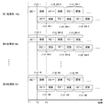
- FIG. 8 schematically shows a process transition when the first processing unit 58a, the second processing unit 58b,..., And the Nth processing unit 58n of the contour searching unit 56 perform the contour searching process.
- the right direction of the figure is the time axis, and from time T1, the N processing units of the first processing unit 58a to the N-th processing unit 58n perform knot 1, knot 2, ..., knot N of a certain candidate curve.
- Execute search processing request When the search processing request is read from the contour search task queue 52, each processing unit copies the image data of the area specified by the search processing request from the contour image in the image storage unit 24 to the subordinate local memory and starts the search processing. To do.
- the time required for copying and the time required for searching are each represented by a rectangle.
- pipeline processing is performed by starting a copy of the area specified by the search processing request read from the contour search task queue 52 next time.
- Reduce processing time In the example of the figure, at time T1, the first processing unit 58a corresponds to the knot 1, the second processing unit 58b corresponds to the knot 2,..., The Nth processing unit 58n corresponds to the knot N.
- the copying of the image data of the area to be started is started.
- the search for the contour line in the copied area is started.
- the first processing unit 58a, the second processing unit 58b,..., The N-th processing unit 58n are knots N + 1, knots N + 2,.
- the search area is copied by pipeline processing.
- FIG. 8 shows a case where the time required for copying and the time required for search processing are almost the same, but the present embodiment is not limited to this. That is, copying of the next area to be processed is started at any timing in the time zone during which the contour search process is performed for a certain area, and when the previous search is completed and the copy is also completed, the search process is performed for the area. Any other embodiment may be used. However, as shown in FIG. 8, when the copy time and the search processing time are substantially equal, it is possible to absorb the overhead that the search processing is not started due to the completion of the copy. When copying the entire contour image and continuously performing contour search for all knots, it takes time to copy image data of a large size first. As described above, the processing time can be shortened.
- the size of the search area may be adjusted so that the time required for copying and the time required for search processing are approximately the same. For example, before the actual tracking process, an experiment is performed in a search area of various sizes using a test image having a similar image configuration, the number of cycles required for each process is measured, and the area is cut out so that they are approximately equal The size may be determined. At this time, the contour image cutout unit 50 controls the contour search unit 56 to actually perform the search process, and acquires the time required for the copy and search process, thereby determining the most efficient size of the search region. Feedback control may be performed.
- the contour search for one knot needs to be shortened as the number of tracking objects increases. Even in such a case, it is possible to shorten the copy and search processing time by adjusting the size of the region by experimenting prior to the actual tracking processing and reducing the size.
- a table in which the optimum size of the search area is set for various numbers of tracking targets is prepared in advance, and after starting tracking, the contour image cutout unit 50 refers to the table when the number of tracking targets is acquired.
- the size of the search area may be determined.
- a table that can determine the size of the search area from parameters that determine the ease of tracking, such as the shape of the candidate curve, the complexity of the operation, and the contrast of the image, and various factors such as the required tracking accuracy May be prepared.
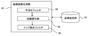
- FIG. 9 shows a detailed configuration of the contour image generation unit 22.
- the contour image generation unit 22 includes a smoothing filter 62, a gradation reduction unit 64, and an edge extraction filter 66.
- the contour image generation unit 22 reads the image frame of the input image stored in the image storage unit 24, smoothes it with the smoothing filter 62, lowers the gradation with the gradation reduction unit 64, and extracts the edge with the edge extraction filter 66. Are applied in this order to generate a contour image.
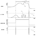
- FIG. 10 is a diagram for explaining a difference between a general edge extraction process and a contour image generation process in the present embodiment.
- the horizontal axis of the graph in the figure all represents the position of the image, that is, the arrangement of pixels, and the range is common.
- the uppermost graph represents the distribution of luminance values of the original image that is the input image.
- the figure shows a pixel row in which an image to be tracked exists in a region 110 indicated by an arrow, and a pixel A and a pixel B have a contour to be tracked.
- the change in the luminance value in the vicinity of the pixel A is gentler with respect to the position than the change in the luminance value in the vicinity of the pixel B.
- Such a situation can frequently occur when the tracking target and the background color are similar in the vicinity of the pixel A, or only the pixel A side is in the shade.
- the luminance value is not constant because the color is changed or the shadow is formed in the region 110 of the image to be tracked, and the luminance value varies like the unevenness 112.
- the edge When generating an edge image of an original image showing such a luminance value distribution, the edge is generally extracted by filtering with an edge extraction filter such as a Laplacian filter. At this time, a threshold value is set for the magnitude of the change of the luminance value with respect to the image plane, and a portion where a change exceeding the threshold value is seen is extracted as an edge.
- the second row of FIG. 10 shows a graph when the edge image is generated as described above. That is, the magnitude of the amount of change in luminance value as shown in the graph is calculated as an edge value, and a portion having an edge value exceeding a preset threshold value 116, that is, a pixel in the vicinity of the pixel B is extracted as an edge. .
- the vicinity of pixel A which is the other contour, is not extracted as an edge because its edge value is smaller than the threshold value 116.
- the threshold value 116 is set to a small value, but by doing so, a portion having a relatively large edge value due to the unevenness 112 of the luminance value that is not related to the contour. 114 is also extracted as an edge.
- candidate curves are set for the contour of the tracking target, and the likelihood is observed by matching with the actual contour to estimate the position of the tracking target. Therefore, if there is a portion that is not extracted from the contour line, or if many lines other than the contour are extracted, the tracking accuracy naturally decreases.
- the optimum value changes for each image, and depending on the image, it can be said that it is an optimum value in the first place. There can be situations where there is no value.
- the present embodiment it is possible to extract the “outline of an object” rather than “the edge in the image” by roughly capturing the object as a surface from detailed information such as lines and gradations in the image.
- a low gradation image in which the luminance value of the original image is reduced is generated.
- the luminance value of the original image is represented by three gradations for easy understanding.
- the luminance value of the area 110 where the tracking target exists discontinuously changes from the luminance value of the other area, and becomes information indicating the presence of the tracking target as the area. .
- the contour image generation unit 22 first smoothes the image frame of the input image by the smoothing filter 62.
- the smoothing filter 62 a general smoothing filter such as a Gaussian filter, a median filter, a simple averaging filter, or a low-pass filter can be used. This removes excess high-frequency components and makes it easier to grasp the surface of the object as a region.
- the gradation-lowering unit 64 generates a gradation-reduced image as described above.
- the gradation reduction unit 64 can be realized by a general bit shift operation, and divides luminance values at predetermined boundaries, and converts the luminance values in each division into one luminance value.
- the luminance value may be equally divided from the bottom, or a luminance value that makes the number of pixels uniform when the color histogram of the image frame is created and divided may be used as the boundary.
- a general posterization method may be used.
- the number of gradations of the low gradation image can be about 8 to 32 gradations, for example.
- the number of gradations of the low gradation image may be reset depending on the tracking target, background, image content, type, and the like.
- a low gradation image having various gradations is generated by using a test image similar to that at the time of actual tracking, and a gradation that can generate a contour image with the highest accuracy or that does not fail tracking is obtained.
- an edge extraction filter 66 is applied to the low gradation image obtained by the gradation reduction unit 64 to generate a contour image.
- a general edge extraction filter such as a Laplacian filter, a Sobel filter, or a Canny edge filter can be used. Thereby, a binary image having different values in the contour portion and other portions is obtained as the contour image.
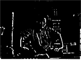
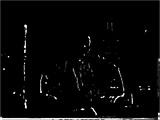
- FIG. 11 shows an example of an original image to be processed.
- 12 and 13 show the result of generating an edge image for the original image by a general edge image generation method.
- FIG. 12 shows a case where the threshold is low, and
- FIG. 13 shows a case where the threshold is high. It is an edge image.
- FIG. 12 in addition to the contour of the person who is the subject, many edges such as clothes patterns, wrinkles and facial parts are extracted, making it difficult to distinguish from the contour. Also, almost no edge is extracted from the shadowed portion on the left side of the person's head.
- the threshold value is increased, as shown in FIG. 13, the number of extracted edges decreases, and the outline is hardly extracted.
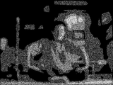
- FIG. 14 shows a low gradation image obtained by processing the original image shown in FIG. 11 by the smoothing filter 62 and the gradation reduction part 64 of the contour image generation unit 22 in the present embodiment.
- the low gradation image detailed information such as a clothing pattern as seen in the edge image of FIG. 12 is omitted, and the image is obtained by capturing the surface of a person or an object as an area.
- FIG. 15 shows a contour image generated by performing edge extraction processing on the low gradation image by the edge extraction filter 66.
- the outline of the person or object is represented by a continuous line, and in FIG. 12, the outline is also extracted from the left side of the person's head where no edge is extracted.
- the main purpose of this embodiment is to track the movement of a person or object in an image, priority is given to the presence of a contour line and information about the approximate position over detailed information of the image at the pixel level. By taking it out, it is possible to correctly detect the movement without mistaking or losing the tracking target.
- the gradation reduction process has the meaning of roughly dividing the image into regions based on the luminance value, and the boundaries of the regions generated thereby are regarded as contours, so that the lines are not interrupted in the middle and the search is easy. .
- a general edge image often appears with a certain width for pixels whose edge value exceeds a threshold value. This is because, as shown in the second stage of FIG. 10, the normal edge value changes approximately continuously with multiple gradations and reaches the peak with a certain width. Further, the lower the threshold value 116 is set so as to extract the edge reliably, the wider the extracted edge becomes.
- the gradation changes greatly even in adjacent pixels, and the edge value peaks in one pixel. Therefore, the extracted portion is a pixel unit, and the extraction result is linear. become. If the edge has a width, processing for thinning the edge is required to match the candidate curve. However, in the case of the contour line in this embodiment, this processing is not necessary, and tracking is performed at a high speed with a simpler configuration. Processing can be performed.
- the contour search process is divided for each knot. Assign to multiple processors and process in parallel. Since the contour search process is independent for each knot, allocation to processors and integration of results are easy. In addition, since the image data necessary for the contour search process for one knot is a limited area near the knot, the data size is small, and each processor copies the data to the local memory and performs the contour search process. Can be executed. Therefore, access to the contour image data can be performed at high speed, and the processing speed can be further improved.
- the number of processors required varies depending on the number of tracking targets, so if the number of tracking targets is smaller than the number of processors, the processing capacity of the device will be used up sufficiently. Disappear. Conversely, if the number of tracking targets is larger than the number of processors, some of the processing that could not be allocated will be executed later, eventually resulting in the possibility of surplus processing capacity.
- the image data size required for each search process varies greatly depending on the size of the tracking target, a memory capacity shortage or a data transfer time fluctuation may occur. Thus, if the processing time and the required memory size vary greatly depending on the contents of the input image, it may become an obstacle to determining the specifications of the apparatus, and the versatility will be poor.
- the search processing is divided for each knot to make the granularity of processing units finer and the number of processing units is increased, so that even if the tracking conditions such as the number of tracking people and the size of the tracking target change, There is little influence on processing time and required memory size, and it is easy to estimate those parameters. Therefore, the specification of the apparatus can be easily determined, and the tracking process can be performed in a suitable environment regardless of the contents of the input image. Similarly, parallel processing is possible with the same processing procedure regardless of the number of processors, and processing units of several thousand orders or more are generated per frame, so that they can be easily allocated to each processor. Since the processing unit is completed in a relatively short time, the scalability is high.
- the boundary between the surfaces can be extracted as a contour line.
- many extra edges other than the contour line are extracted depending on the threshold value for extraction, or the contour line is interrupted, which affects the tracking accuracy.
- the boundary between the surfaces is emphasized as described above, the allowable range of the threshold is wide, and the contour line can be easily extracted.
- the smoothing filter, low gradation part, and edge extraction filter used for contour image generation can all be processed by raster scan, and are independent processing for each line. Is possible. Further, since the contour image generated in the present embodiment appears in a line shape having a width corresponding to one pixel, it is not necessary to perform a thinning process for likelihood observation.
- Embodiment 2 In the first embodiment, knots and search areas are cut out in a one-to-one correspondence, and a contour search request is issued to each knot.
- the contour image is divided into a predetermined size in advance, and a contour search request is issued for each divided region.
- the configurations of the tracking device 14 and the observation unit 30 are the same as those shown in FIGS. 4 and 6, and the main processing procedure is the same as the procedure described in the first embodiment.
- description of the same processing as in the first embodiment will be omitted, and description will be made focusing on differences from the first embodiment.
- FIG. 16 shows that the first processing unit 58a, the second processing unit 58b, the third processing unit 58c,...,
- the Nth processing unit 58n of the contour search unit are stored in the image storage unit 24 in the present embodiment.
- FIG. 6 schematically shows how the image data of the divided area is copied from the contour image to the respective local memories 60a, 60b, 60c,..., 60n.
- the contour image is divided regardless of the knot position.
- the contour image 90 is divided into six equal parts in the horizontal direction and five equal parts in the vertical direction. At this time, the number of divisions is determined in advance so that the size of each divided area 98 is equal to or less than the capacity of the local memories 60a, 60b, 60c,. Further, the division may not be performed equally. Coordinate information of such division patterns is stored in advance in the image storage unit 24 and the like, and the image cutout unit 50 reads out the information.
- the image cutout unit 50 determines which region the candidate curve knot 96 is included in for all candidate curves determined by the particles determined by the sampling unit 29. Then, a region 98 including the knot 96 is extracted, and a contour search processing request including information related to the region and coordinate information of all knots included in the region 98 is issued to the contour search task queue 52.
- the information related to the area to be included in the contour search request may be only the identification information. Get better.
- the Nth processing unit 58n of the contour search unit 56 read one contour search processing request from the contour search task queue 52, Based on the identification information of the designated area 98, the image data of the designated area 98 is copied from the contour image 90 stored in the image storage unit 24 to the subordinate local memory. Then, based on the coordinate information of the knot, the contour line closest to the knot is searched in the copied area. When a plurality of knots are included in the copied region, the contour line search is continuously performed for all knots, and the result of scoring for each knot is output to the likelihood acquisition unit 54. When the search is completed for all the knots included in the copied area, the next contour search processing request is read from the contour search task queue 52, and the same processing is repeated.
- the property is used to reduce the frequency of the area copy processing.
- the search processing for a part of the region copied at once is executed at a time regardless of which candidate curve knots, thereby increasing the processing efficiency.
- the likelihood acquisition unit 54 refers to the information that associates the knot information with the identification information of the candidate curve to which the knot belongs, so that each candidate curve is referred to. Likelihood can be obtained.
- the contour image is divided into a predetermined pattern, the contour search processing is divided for each divided region, assigned to a plurality of processors, and processed in parallel.
- Each processor copies the divided area to the local memory, and searches for the contour line in the copied area for all knots included in the area regardless of the candidate curve. Due to the nature of the particle filter, there are many situations where multiple candidate curves are close to each other and there are many knots in a limited area. The efficiency of the search can be improved. As a result, the processing can be advanced at a higher speed by the synergistic effect with the parallel processing and the use of the local memory described in the first embodiment.
- the contour image generation unit 22 includes a smoothing filter 62, a gradation reduction unit 64, and an edge extraction filter 66 as shown in FIG. 9, and generates a contour image by these processes.
- the contour image generation unit 22 may be a general edge extractor.
- the contour image generation unit 22 may include only the smoothing filter 62 and the edge extraction filter 66.
- the surface or background of the tracking target is not complicated, it is possible to generate an outline image with an edge extractor. Also in this case, the likelihood can be observed by performing an edge search using the generated edge image. High-speed tracking processing becomes possible by parallel processing.
- the contour image generation unit 22 may generate a contour image using a foreground extractor (not shown). For example, when the movement of a player is tracked using an image of a soccer game as an input image, the main background is the ground and the player wears a uniform, so each pixel value is limited. In such a case, the outline of the tracking target can be accurately extracted by a general foreground extraction process. A table associating them may be prepared so that the outline image generation unit 22 can determine which processing is performed according to the type of the input image. Or you may enable a user to change a setting.
- the contour image generation unit 22 may be provided in an image processing device other than the tracking device 14.
- an apparatus for automatically taking a photograph may be provided, and the image of the subject may be once captured and the contour image of the subject may be generated by the contour image generation unit 22.
- the position of the subject is calculated from the contour image, and the information is fed back to the camera orientation and position control device to automatically adjust the subject so that it appears in a desired position such as the center of the photograph.
- the present invention can be used for information processing apparatuses such as a visual tracking apparatus, a computer, a game machine, an imaging apparatus, and a moving image reproduction apparatus.
Abstract
図7において、1つ前のフレームにおける追跡対象の存在確率分布に基づき、パーティクルフィルタを用いて現在のフレームにおける追跡対象の輪郭の候補曲線を定める。候補曲線と現在のフレームの輪郭画像90とをマッチングするために、候補曲線を構成するノット92ごとに、候補曲線の最近傍にある輪郭線を探索する処理を分割し、複数の処理部によって並列に実行する。各処理部のローカルメモリ60a~60dには、画像記憶部24に格納した輪郭画像90から、処理対象のノット92の探索領域94の画像データをコピーする。
Description
本発明は情報処理技術に関し、特に入力画像中の対象物の追跡を行う対象物追跡装置およびそこで実行される対象物追跡方法に関する。
視覚追跡はコンピュータビジョン、特にセキュリティ分野における視覚監視やAV分野における記録映像の解析・分類、編集、またはマンマシンインターフェース、さらには人間同士のインターフェース、すなわちテレビ会議やテレビ電話など、多岐に渡る応用が見込まれる。そのため、追跡精度および処理効率の向上等を目的に、多くの研究がなされている。中でも、カルマンフィルタで扱うことのできない非ガウス性雑音が加算された信号の時系列解析手法として注目されているパーティクルフィルタを視覚追跡に応用する研究が多くなされており、特にCondensation(Conditional Density Propagation)アルゴリズムが有名である(例えば非特許文献1から非特許文献3参照)。
パーティクルフィルタはベイズフィルタの近似計算法であり、有限個のパーティクルを追跡候補として導入することにより対象の確率分布を表現し、それを用いて時系列推定や予測を行う。Condensationアルゴリズムはパーティクルフィルタを用いて、追跡対象の形状についての確率分布の時間変化を推定する。具体的には、追跡対象と同一形状を有する候補の輪郭線を1つのパーティクルで表し、運動モデルによるパラメータ遷移と観測による遷移結果の尤度計算によって、対象のパラメータ空間上での存在確率分布を逐次推定する。
Contour tracking by stochastic propagation of conditional density, Michael Isard and Andrew Blake, Proc. European Conf. on Computer Vision, vol. 1, pp.343-356, Cambridge UK (1996) CONDENSATION - conditional density propagation for visual tracking, Michael Isard and Andrew Blake, Int. J. Computer Vision, 29, 1, 5-28 (1998) ICondensation: Unifying low-level and high-level tracking in a stochastic framework, Michael Isard and Andrew Blake, Proc 5th European Conf. Computer Vision, 1998
Contour tracking by stochastic propagation of conditional density, Michael Isard and Andrew Blake, Proc. European Conf. on Computer Vision, vol. 1, pp.343-356, Cambridge UK (1996) CONDENSATION - conditional density propagation for visual tracking, Michael Isard and Andrew Blake, Int. J. Computer Vision, 29, 1, 5-28 (1998) ICondensation: Unifying low-level and high-level tracking in a stochastic framework, Michael Isard and Andrew Blake, Proc 5th European Conf. Computer Vision, 1998
パーティクルフィルタを利用して視覚追跡を行う場合、当然、早い処理速度で結果が出力されることが望ましい。このことは、撮影中の映像における対象物をリアルタイムで追跡する場合は特に重要である。この場合、1フレームごとに必要な処理、すなわちパーティクルの生成消滅、各パーティクルが定める候補の輪郭線とそのフレームのエッジ画像とのマッチング、尤度取得、存在確率分布の推定、といった処理をフレームの入力周期以内に終了させる必要がある。しかし、追跡対象の数や大きさが変化すると、処理時間や処理に必要なリソースが変動してしまうため、それらのパラメータの見積もりが難しく、常に最適な環境で高速に追跡処理を行うことは困難であった。
本発明はこのような課題に鑑みてなされたものであり、追跡処理の効率性が追跡対象の変化の影響を受けにくく、スケーラビリティの高い視覚追跡技術を提供することにある。
本発明のある態様は対象物追跡装置に関する。この対象物追跡装置は、追跡したい対象物を撮影した動画像データを構成する画像ストリームに含まれる第1の画像フレームおよび第2の画像フレームのうち、第1の画像フレームにおける対象物の推定存在確率分布に基づき、第2の画像フレームにおける対象物の候補輪郭を定める候補輪郭決定部と、候補輪郭決定部が定めた候補輪郭と、第2の画像フレームのエッジ画像とをマッチングして、候補輪郭の尤度を観測する観測部と、観測部が観測した尤度に基づき、第2の画像フレームにおける対象物の存在確率分布を推定する結果取得部と、を備え、観測部は、候補輪郭の曲線を構成するノットから最近傍にあるエッジを探索する処理を、当該ノットごとに並列に実行する複数の探索部と、探索部が探索した結果を統合して候補輪郭ごとに尤度を求める尤度取得部と、を備えたことを特徴とする。
ここで「第1の画像フレーム」と「第2の画像フレーム」は、画像ストリームにおいて隣接する画像フレームでもよいし、離れて位置する画像フレームでもよい。時間軸の順方向へ追跡していく一般的な対象物追跡においては、「第1の画像フレーム」は「第2の画像フレーム」より時間的に前の画像フレームであるが、本実施の形態はこれに限らない。
「存在確率分布」は、対象物の画像フレーム内の位置座標に対する存在確率分布であってもよいし、形状、色、大きさなど対象物の有する属性のいずれかまたはそれらの組み合わせを表すパラメータが張る空間に対する存在確率分布であってもよい。「候補輪郭」は対象物の一部または全体の輪郭線の候補を表す図形である。また「尤度」は候補輪郭がどの程度対象物と近い態様となっているかを表す度合いであり、例えば対象物との重なり具合、対象物との距離などを数値で示したものなどである。
本発明の別の態様は対象物追跡方法に関する。この対象物追跡方法は、追跡したい対象物を撮影した動画像データを構成する画像ストリームに含まれる第1の画像フレームおよび第2の画像フレームのうち、第1の画像フレームにおける対象物の推定存在確率分布に基づき、第2の画像フレームにおける対象物の候補輪郭を定めるステップと、第2の画像フレームのエッジ画像を生成してメモリに格納するステップと、メモリに格納したエッジ画像の一部の領域の画像データを読み出し、探索することにより、候補輪郭の曲線を構成するノットから最近傍にあるエッジを検出する処理を、ノットごとに並列に実行するステップと、エッジ検出の結果を統合して候補輪郭ごとに尤度を求め、第2の画像フレームにおける対象物の存在確率分布を推定するステップと、を含むことを特徴とする。
なお、以上の構成要素の任意の組合せ、本発明の表現を方法、装置、システム、コンピュータプログラム、コンピュータプログラムを記録した記録媒体などの間で変換したものもまた、本発明の態様として有効である。
本発明によれば、高速でスケーラビリティの高い視覚追跡技術を実現することができる。
10 視覚追跡システム、 12 撮像装置、 14 追跡装置、 16 表示装置、 20 画像取得部、 22 輪郭画像生成部、 24 画像記憶部、 26 追跡処理部、 28 追跡開始終了判定部、 29 サンプリング部、 30 観測部、 34 結果取得部、 36 結果記憶部、 40 出力制御部、 50 輪郭画像切り出し部、 52 輪郭探索タスクキュー、 54 尤度取得部、 56 輪郭探索部、 58a 第1処理部、 60a ローカルメモリ、 62 平滑化フィルタ、 64 低階調化部、 66 エッジ抽出フィルタ。
実施の形態1
初めに、本実施の形態の特徴および効果を明らかにするために、パーティクルフィルタによる視覚追跡について概説する。図1は人物を追跡対象とした場合の視覚追跡手法を説明するための図である。人物画像150は実写した動画像やコンピュータグラフィックスなどにより生成された動画像の画像ストリームを構成する画像フレームのひとつであり、追跡対象である人物152が写っている。
初めに、本実施の形態の特徴および効果を明らかにするために、パーティクルフィルタによる視覚追跡について概説する。図1は人物を追跡対象とした場合の視覚追跡手法を説明するための図である。人物画像150は実写した動画像やコンピュータグラフィックスなどにより生成された動画像の画像ストリームを構成する画像フレームのひとつであり、追跡対象である人物152が写っている。
この人物152の動きを追跡するために、人物152の頭部輪郭の形状を近似するΩ形の曲線154を既知の表現で記述する。一方、人物152を含む人物画像150にはエッジ抽出処理を施し、エッジ画像を取得しておく。そして曲線154を規定するパラメータを変化させながら形状および位置を変化させて、その近傍にあるエッジを探索することにより、人物152の頭部輪郭と最もマッチすると推定されるパラメータの値を特定する。以上の処理をフレームごとに繰り返すことにより人物152の追跡が進捗する。ここでエッジとは一般的には画像の濃度や色に急な変化を有する箇所のことである。
様々な曲線154と人物152の頭部輪郭とのマッチングを行うために、パーティクルフィルタによる確率分布予測技術を導入する。すなわち、ひとつ前のフレームにおけるパラメータ空間上の対象物の確率分布に応じて曲線154のサンプリング数を増減させ、追跡候補の絞り込みを行う。これにより存在確率の高い部分に対しては重点的に探索を行うことができ、精度のよいマッチングが効率的に行える。
対象物の輪郭に着目した追跡に対するパーティクルフィルタの適用手法は、例えば非特許文献3(ICondensation: Unifying low-level and high-level tracking in a stochastic framework, Michael Isard and Andrew Blake, Proc 5th European Conf. Computer Vision, 1998)に詳述されている。ここでは本実施の形態に係る点に着目して説明する。
まずΩ形の曲線154を、Bスプライン曲線で記述する。Bスプライン曲線はn個の制御点列(Q0,・・・,Qn)とノット列(s0,・・・,sn)とから定義される。そして基本となる曲線形状、この場合はΩ形の曲線となるように、それらのパラメータをあらかじめ設定しておく。このときの設定によって得られる曲線を以後、テンプレートQ0と呼ぶ。なお、図1で示した人物画像150における人物152の追跡を行う場合は、テンプレートQ0はΩ形であるが、その形状は追跡対象によって変化させる。すなわち追跡対象がボールであれば円形、手のひらであれば手の形状などとなる。
次にテンプレートの形状を変化させるための変換パラメータとして、形状空間ベクトルxを準備する。形状空間ベクトルxは以下のような6つのパラメータで構成される。

ここで(shiftx,shifty)は(x,y)方向への並進量、(extendx,extendy)は倍率、θは回転角である。そして形状空間ベクトルxをテンプレートQ0に作用させるための作用行列Wを用いると、変形後の曲線、すなわち候補曲線Qは以下のように記述できる。
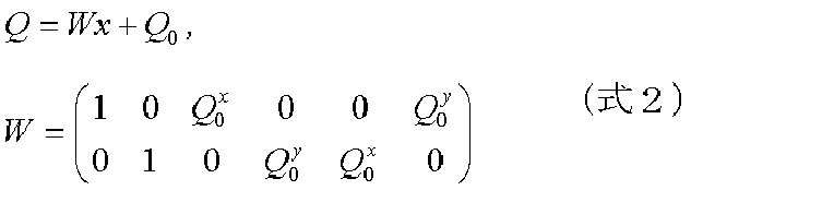
式2を用いれば、形状空間ベクトルxを構成する6つのパラメータを適宜変化させることにより、テンプレートを並進、伸縮、回転させることができ、組み合わせによって候補曲線Qの形状や位置を種々変化させることができる。
そして、制御点列、およびノット列の間隔といったテンプレートQ0のパラメータや、形状空間ベクトルxを構成する6つのパラメータを変化させることによって表現される複数の候補曲線について、各ノットの近傍にある人物152のエッジを探索する。その後、エッジとの距離などから各候補曲線の尤度を求めることにより、形状空間ベクトルxを構成する6つのパラメータが張る6次元空間における確率密度分布を推定する。
図2はパーティクルフィルタを用いた確率密度分布推定の手法を説明する図である。同図では理解を簡単にするために、形状空間ベクトルxを構成する6つのパラメータのうち、あるパラメータx1の変化を横軸に表しているが、実際には6次元空間において同様の処理が行われる。ここで確率密度分布を推定したい画像フレームが時刻tの画像フレームであるとする。
まず、時刻tの画像フレームのひとつ前のフレームである時刻t-1の画像フレームにおいて推定された、パラメータx1軸上の確率密度分布を用いて(S10)、時刻tにおけるパーティクルを生成する(S12)。それまでにフィルタリングを行い、すでにパーティクルが存在する場合は、その分裂、および消滅を決定する。S10において表した確率密度分布は、パラメータ空間上の座標に対応して離散的に求められたものであり、円が大きいほど確率密度が高いことを表している。
パーティクルはサンプリングするパラメータx1の値とサンプリング密度とを実体化したものであり、例えば時刻t-1において確率密度が高かったパラメータx1の領域は、パーティクル密度を高くすることで重点的にサンプリングを行い、確率密度の低かった範囲はパーティクルを少なくすることでサンプリングをあまり行わない。これにより、例えば人物152のエッジ近傍において候補曲線を多く発生させて、効率よくマッチングを行う。
次に所定の運動モデルを用いて、パーティクルをパラメータ空間上で遷移させる(S14)。所定の運動モデルとは例えば、ガウシアン型運動モデル、自己回帰予測型運動モデルなどである。前者は、時刻tにおける確率密度は時刻t-1における各確率密度の周囲にガウス分布している、とするモデルである。後者は、サンプルデータから取得した2次以上の自己回帰予測モデルを仮定する手法で、例えば人物152がある速度で等速運動をしているといったことを過去のパラメータの変化から推定する。図2の例では、自己回帰予測型運動モデルによりパラメータx1の正方向への動きが推定され、各パーティクルをそのように遷移させている。
次に、各パーティクルで決定される候補曲線の近傍にある人物152のエッジを、時刻tのエッジ画像を用いて探索することにより、各候補曲線の尤度を求め、時刻tにおける確率密度分布を推定する(S16)。前述のとおり、このときの確率密度分布はS16に示すように、真の確率密度分布400を離散的に表したものになる。以降、これを繰り返すことにより、各時刻における確率密度分布がパラメータ空間において表される。例えば確率密度分布が単峰性であった場合、すなわち追跡対象が唯一であった場合は、得られた確率密度を用いて各パラメータの値に対し重み付けした和を最終的なパラメータとすることにより、追跡対象に最も近い輪郭の曲線が得られることになる。
S16において推定される時刻tにおける確率密度分布p(xt
i)は以下のように計算される。
ここでiはパーティクルに一意に与えられた番号、p(xt
i|xt
i, ut-1)は所定の運動モデル、p(yt|xt
i)は尤度である。
図3は本実施の形態における視覚追跡システムの構成例を示している。視覚追跡システム10は、追跡対象18を撮像する撮像装置12、追跡処理を行う追跡装置14、撮像装置12が撮像した画像のデータや追跡結果のデータを出力する表示装置16を含む。追跡対象18は人、物、それらの一部など、視覚追跡システム10の使用目的によって異なっていてよいが、以後の説明では上記の例同様、人であるとする。
追跡装置14と、撮像装置12あるいは表示装置16との接続は、有線、無線を問わず、また種々のネットワークを介していてもよい。あるいは撮像装置12、追跡装置14、表示装置16のうちいずれか2つ、または全てが組み合わされて一体的に装備されていてもよい。また使用環境によっては、撮像装置12と表示装置16は同時に追跡装置14に接続されていなくてもよい。
撮像装置12は追跡対象18を含む画像、または追跡対象18の有無に関わらずある場所の画像のデータを、所定のフレームレートで取得する。取得された画像データは追跡装置14に入力され、追跡対象18の追跡処理がなされる。処理結果は出力データとして追跡装置14の制御のもと、表示装置16へ出力される。追跡装置14は別の機能を実行するコンピュータを兼ねていてもよく、追跡処理の結果得られたデータ、すなわち追跡対象18の位置情報や形状情報などを利用して様々な機能を実現してよい。
図4は本実施の形態における追跡装置14の構成を詳細に示している。追跡装置14は、撮像装置12から入力される入力画像データを取得する画像取得部20、当該入力画像データや輪郭画像データを記憶する画像記憶部24、入力画像データから輪郭画像を生成する輪郭画像生成部22、追跡の開始および終了を判定する追跡開始終了判定部28、パーティクルフィルタを用いて追跡処理を行う追跡処理部26、最終的な追跡結果のデータを記憶する結果記憶部36、追跡結果の表示装置16への出力を制御する出力制御部40を含む。
図4において、様々な処理を行う機能ブロックとして記載される各要素は、ハードウェア的には、CPU、メモリ、その他のLSIで構成することができ、ソフトウェア的には、画像処理を行うプログラムなどによって実現される。したがって、これらの機能ブロックがハードウェアのみ、ソフトウェアのみ、またはそれらの組合せによっていろいろな形で実現できることは当業者には理解されるところであり、いずれかに限定されるものではない。
輪郭画像生成部22は追跡対象の輪郭線を入力画像の画像フレームから抽出し、輪郭画像を生成する。当該輪郭画像は画像記憶部24に格納され、後に追跡処理部26の観測部30において候補曲線の尤度観測に用いられる。通常、「輪郭線」はエッジ画像における「エッジ」として扱われるため、従来の技術では「エッジ画像」を用いた尤度観測が行われていた。しかし一般的なエッジ抽出フィルタでは、入力画像によっては物の輪郭線以外にも多くのエッジが抽出されるため、輪郭線以外のエッジとのマッチングにより尤度観測が正確に行われないことが考えられる。また、エッジ抽出のしきい値を高く設定してエッジの数を減らすと、輪郭線がとぎれてしまい、やはり尤度観測が正確に行われない可能性がある。
そこで本実施の形態の輪郭画像生成部22は、一般的な「エッジ画像」ではなく、特に入力画像中の物の「輪郭」に着目し、尤度観測を精度よく行うことのできる画像を生成する。具体的な手法は後に述べるが、以後の説明では、輪郭画像生成部22が生成する画像を「輪郭画像」として一般的な「エッジ画像」と区別する。また輪郭画像生成部22は、背景差分を利用した前景抽出器(図示せず)を実装していてもよい。そして輪郭画像生成処理の前処理として入力画像から追跡対象を含む前景を抽出することにより、追跡対象の輪郭を効率的に抽出するようにしてもよい。
追跡開始終了判定部28は、例えば輪郭画像生成部22によって得られた輪郭線または前景の形状を評価し、所定の条件によって、追跡を開始するか終了するかを判定する。なおここでの「終了」はオクルージョンなどによる追跡の一時停止を含んでもよい。追跡は、追跡対象が撮像装置の視野角内に現れた場合や、物陰などから現れた場合などに開始し、追跡対象が撮像装置の視野角内から去った場合や物陰などに入った場合などに終了する。追跡を開始すると判定した場合は、追跡処理部26にその旨の通知をし、追跡処理を開始させる。
追跡処理部26は、サンプリング部29、観測部30、および結果取得部34を含む。サンプリング部29は、一つ前の時刻t-1における画像フレームに対して推定された確率密度分布に基づき、パーティクルの生成および消滅の処理を行う。そして全てのパーティクルに対し所定の運動モデルを適用して、パーティクルをパラメータ空間上で遷移させる。これにより、時刻tの画像フレームにおける複数の候補曲線が決定する。サンプリング部29は、追跡開始終了判定部28から追跡開始を示す信号を受けたら処理を開始し、追跡終了を示す信号を受けたら処理を終了する。
観測部30はサンプリング部が生成・消滅、遷移させた各パーティクルが定める候補曲線の尤度を観測する。例えば各パーティクルが定める候補曲線をそれぞれBスプライン曲線で表現した場合、当該Bスプライン曲線のノットごとに、輪郭画像生成部22が生成した輪郭画像において最近傍にある輪郭線を探索し距離を求めることにより、所定のルールでノットをスコアリングする。そして候補曲線を構成する全ノットのスコアに基づき当該候補曲線の尤度を求める。観測部30は、複数のプロセッサユニットを利用してこの探索処理を並列に実行する。
詳細な手法は後に述べるが、本実施の形態では、輪郭線の探索処理をノットごとに分割したものを一の処理単位とし、複数のプロセッサユニットで並列処理する。各プロセッサユニットは、一のノットの最近傍にある輪郭線を探索するために、輪郭画像のうち、当該ノットとその探索領域を含む一部の領域の画像データのみを配下のローカルメモリにコピーする。この処理を複数のプロセッサで繰り返すことにより、一の追跡対象につき、(パーティクルの数)×(候補曲線を構成するノットの数)の個数の処理単位を短時間で処理する。それぞれのプロセッサユニットが並列に取得した各ノットのスコアは候補曲線ごとに統合し、尤度を算出する。スコアリングや尤度算出の手法は従来技術を採用できる。
結果取得部34は、観測部30が観測した尤度に基づき式3で示すような確率密度分布p(xt
i)を算出し、それにより重み付け平均したパラメータによって得られる曲線のデータなどの追跡結果を算出し、結果記憶部36に格納する。また次の時刻t+1における追跡処理に使用するため、サンプリング部29にそのデータを返す。結果記憶部36に格納するデータは、重み付け平均した各パラメータの値でもよいし、それにより定まる曲線のみで構成される画像や、曲線と入力画像とを合成してできた画像のデータなどのいずれでもよい。
追跡対象が複数存在する場合、結果取得部34はさらに、それぞれに用意したテンプレートを用いて、追跡対象ごとに追跡を行い、それらの追跡結果を合成することによりひとつの追跡結果としてもよい。また複数の追跡対象が重なるような場合を追跡結果によって検出し、後ろに隠れる追跡対象については所定のタイミングで追跡処理対象からはずすなどの措置を講じる。これにより追跡対象が別の追跡対象の背後に回ったことによって観測尤度が一時的に低下しても、不適当な追跡結果を出力するのを避けることができる。
輪郭画像生成部22、追跡処理部26における上述の処理を、各フレームに対して行うことにより、結果記憶部36には例えば追跡結果を含む動画像のデータが記憶される。この場合、出力制御部40の制御のもと、当該動画像のデータを表示装置16に出力することにより、テンプレートの曲線が追跡対象の動きと同様に動く様を表示することができる。なお上述のとおり、追跡結果は動画として表示する以外に、追跡の目的に応じて別の演算モジュールに出力するなどの処理を適宜行ってよい。
次にこれまで述べた構成による追跡装置14の動作について説明する。以下、例としてある場所にいる人物を追跡する場合について説明する。このとき撮像装置12は、撮影対象の場所を所定のフレームレートで撮影する。撮影された画像は入力画像データとして追跡装置14の画像取得部20へ入力され、画像記憶部24に格納される。このような状態において以下に述べる追跡処理が行われる。
図5は本実施の形態における追跡処理の手順を示すフローチャートである。この例の場合、追跡対象は人物であるため、追跡装置14には前述のとおりΩ型のテンプレートを用意する。なおテンプレートの表現手法はBスプライン曲線に限らず、所望の曲線を表現できる記述形式であればよい。またテンプレート形状の変形手法も、その記述形式に適合し、数種類のパラメータを変化させることによって上述のような柔軟な変形を行うことのできる手法を適宜選択してよい。
まず追跡開始終了判定部28は、画像記憶部24に格納された入力画像データをフレームごとに読み出し、追跡を開始するかどうかの判定を行う(S20、S22)。例えば、画像フレームから抽出した前景として、人物と推定できる所定のサイズ、形を有する対象が出現した場合には、追跡を開始する判定を行う。判定基準となる前景のサイズや形はあらかじめ論理的にまたは実験的に定めておく。前景の抽出処理は、輪郭画像生成部22に実装された図示しない前景抽出器を利用してもよい。この場合は、追跡開始終了判定部28が、輪郭画像生成部22に対し前景抽出処理の要求を行う。あるいは追跡開始終了判定部28が前景抽出器を実装していてもよい。
追跡開始と判定されるまでS20とS22を繰り返し、追跡開始と判定されたら(S22のY)、追跡処理部26が追跡処理を開始する。ここで、追跡開始を判定された画像フレームに対応する時刻をt=0とし、以後の画像フレームは時刻t=1,2,3,・・・にそれぞれ対応するとする。まず、サンプリング部29が輪郭画像生成部22に対し、輪郭画像生成処理の要求を行うことにより、輪郭画像生成部22はt=0画像フレームの輪郭画像を生成する(S26)。このときサンプリング部29は、後続フレームの輪郭画像生成処理要求も行い、輪郭画像生成部22は順次処理を行ってよい。
そしてサンプリング部29は、例えばパラメータ空間の所定領域に均等にパーティクルを配置してサンプリングを行い、観測部30が各パーティクルが定める候補曲線と輪郭画像とをマッチングすることにより尤度を観測し、結果取得部34が式3により率密度分布の初期値p(x0
i)を算出する(S28、S30、S32)。
一方、輪郭画像生成部22は、画像記憶部24より時刻t=1の画像フレームを読み出し輪郭画像を生成する(S34のN、S26)。サンプリング部29は、生成した確率密度分布の初期値p(x0
i)に対応した数のパーティクルをパラメータ空間上に発生させ、所定の運動モデルに基づきパーティクルをそれぞれ遷移させることによりサンプリングを行う(S28)。発生させるパーティクルの数は、追跡装置14が有する演算リソースの量や、求められる結果出力速度などに基づき、処理の負荷を考慮して制御する。運動モデルは追跡対象の種類に応じてガウシアン型運動モデル、自己回帰予測型運動モデルなどから追跡精度が高く得られるものをあらかじめ決定しておく。
すると観測部30は、遷移後のパーティクルが定める各候補曲線の尤度p(yt|xt
i)を観測する(S30)。尤度の観測は、輪郭画像生成部22が生成した時刻t=1の輪郭画像を用いて、各候補曲線近傍にある輪郭線を探索することにより行われる。このとき上述のとおり、探索処理をノットごとに複数のプロセッサに割り振る。詳細は後に述べる。
次いで結果取得部34は、観測された尤度に基づき時刻t=1の確率密度分布p(x1
i)を求める。複数の追跡対象が存在する場合は、上記の処理を全ての追跡対象について行う。そして結果取得部34は、時刻t=1における追跡対象の形状および位置として、確率密度分布p(x1
i)によって各パラメータを重み付け平均して得られるΩ型の曲線を最終的に決定し、元の入力画像フレームに重ねた画像フレームのデータを生成するなど、所望の追跡結果データを生成して結果記憶部に保存する(S32)。
追跡開始終了判定部28は、追跡処理をこれ以上続行するか終了するかの判定を行う(S34)。例えば人物と推定できる所定のサイズ、形を有する対象が前景として現れない状態が所定時間継続した場合に追跡終了の判定を行う。あるいは、実空間上においてある追跡対象が別の追跡対象の背後に回った場合など、オクルージョンの状態が所定時間継続した場合に追跡終了の判定を行う。オクルージョンの状態は、過去の追跡処理結果から推定してもよいし、図示しない距離計測系などによって検出してもよい。さらに、追跡対象が撮像装置12の画角から外れた状態が所定時間継続した状況も、オクルージョンと同様の手法で検出し、追跡終了の判定を行う。
S34において追跡処理を終了しないと判定した場合は(S34のN)、時刻t=2の画像フレームから輪郭画像を生成するとともに、S32で得られた時刻t=1のときの確率密度分布p(x1
i)を用いて、パーティクルの生成または消滅、および運動モデルによる遷移を行い、時刻t=2のフレームに対する尤度観測、確率密度分布算出を行う(S26~S32)。以降、S34で追跡開始終了判定部28が追跡終了の判定を行うまでS26からS32までの処理を、各フレームに対して繰り返す。これにより、Ω型の曲線が追跡対象の来訪者の頭部と同じ動きおよび形状で、時間に対して変化していくような動画のデータが結果記憶部36に格納される。出力制御部40が当該データを、表示装置16や別の機能を提供するモジュールなどに出力することにより、ユーザは所望の形態で追跡結果を利用することができる。
次にS30において観測部30が候補曲線と輪郭画像上の輪郭線とをマッチングして尤度を観測する処理について説明する。図6は観測部30の構成をより詳細に示している。観測部30は、輪郭画像切り出し部50、輪郭探索タスクキュー52、輪郭探索部56、尤度取得部54を含む。輪郭画像切り出し部50は、候補曲線を表す曲線のノットの座標に基づき、各ノットに対応する領域を輪郭画像から切り出す。ここで各ノットに対応する領域とは、当該ノットとそのノットのための探索領域を含む領域である。探索領域と等しくてもよく、以後の説明では「探索領域」とも呼ぶ。そしてノットの座標情報と、対応する領域に係る情報とを含む輪郭探索の処理要求を発行する。発行された処理要求は輪郭探索タスクキュー52における処理待ち行列に加えられる。
輪郭探索部56は、第1処理部58a、第2処理部58b、第3処理部58c、・・・、第N処理部58nのN個の処理ユニットと、それぞれに接続するローカルメモリ60a、60b、60c、・・・、60nを含む。各処理ユニットは、輪郭探索タスクキュー52より輪郭探索処理要求を順次読み出し、要求されたノットに対して輪郭探索処理を実行する。具体的には、画像記憶部24に格納された輪郭画像から、処理要求で指定された領域の画像データを配下のローカルメモリにコピーする。そして指定されたノットの座標に基づき、当該ノットの最近傍にある輪郭線を、ローカルメモリにコピーした領域内で探索し、所定の規則に則りスコアリングする。
輪郭の探索には一般的に用いられるエッジ探索の手法を利用することができる。そして探索領域は、選択した探索手法やマッチングに求められる精度により決定することができる。第1処理部58a、第2処理部58b、第3処理部58c、・・・、第N処理部58nは各自、1つの処理要求を実行すると、得られたスコアを尤度取得部54に出力する。そして次の輪郭探索処理要求を輪郭探索タスクキュー52より読み出し、同様の処理を繰り返す。
尤度取得部54は、輪郭探索部の第1処理部58a、第2処理部58b、第3処理部58c、・・・、第N処理部58nからそれぞれ入力された各ノットのスコアを統合して、候補曲線ごとの尤度を算出する。具体的には候補曲線を構成する全ノットのスコアを集めて合計したり、平均値を算出したり、所定の変換式に代入する。輪郭探索部56の各処理ユニットからはノットに対するスコアが次々出力されるが、ノットの識別情報と、そのノットが属する候補曲線の識別情報とを対応付けた情報を、観測部30内で共通に保持しておき、処理要求やスコアの出力時に、必要な識別情報を含めることにより、候補曲線ごとに結果を統合できる。
図7は、輪郭探索部56の第1処理部58a、第2処理部58b、第3処理部58c、・・・、第N処理部58nが輪郭探索処理要求に従い、画像記憶部24に格納された輪郭画像から、指定された領域の画像データを各自のローカルメモリ60a、60b、60c、・・・、60dにコピーする様子を模式的に示している。まず画像記憶部24には、輪郭画像生成部22が生成した輪郭画像90が格納されている。そしてサンプリング部29が決定したパーティクルによって、候補曲線の各ノット92の座標が定められる。
輪郭画像切り出し部50はノット92の座標を取得すると、そのノットの探索領域94をノットごとに切り出す。探索領域の決定の仕方は、精度、メモリ容量、処理速度などに鑑み決定する。図7の例では、ノット92の座標を重心とする正方形を探索領域94として切り出している。探索精度の観点から、探索領域94の大きさは、候補曲線の大きさによって変化させることが望ましい。例えば、候補曲線がとり得る最大サイズに対する探索領域94の最大データサイズを、ローカルメモリ60a、60b、60c、・・・、60dのコピー領域に格納できる最大データサイズと等しくなるように設定する。そして探索領域94を、候補曲線の大きさの比率に応じて変化させることにより正方形の大きさを決定する。候補曲線の大きさは、各パーティクルが有するパラメータのうち倍率(extendx,extendy)に基づき決定できる。
探索領域94の決定の仕方は図7で示したものに限らない。後に述べるように当該領域の画像データをローカルメモリ60a、60b、60c、・・・、60dにコピーする時間や、探索処理に要する時間などを考慮して増減させてもよい。また、探索領域94の重心にノットがなくてもよい。例えばパーティクルを運動モデルによって遷移させた際用いた自己回帰予測モデルによって追跡対象の動きを推定し、動くと推定される方向に探索領域94を広く設けるようにしてもよい。また探索領域94は正方形でなくてもよく、探索手法や追跡対象の動きの特徴などによってその他の矩形や菱形、横や縦一列の画素などでもよい。
輪郭画像切り出し部50は、ノット92の座標とそれに対応する探索領域94の情報、例えば正方形の一角の座標と一辺の長さの情報、を含む輪郭探索処理要求を輪郭探索タスクキュー52に入れる。輪郭探索部の第1処理部58a、第2処理部58b、第3処理部58c、・・・、第N処理部58nは、輪郭探索タスクキュー52から輪郭探索処理要求を1つ読み込むと、当該要求に含まれる正方形の情報に基づき画像記憶部24に格納された輪郭画像90から正方形の領域の画像データのみを、配下のローカルメモリにコピーする。
本実施の形態では、処理単位をノットごととすることにより、一の処理単位に必要なデータの量を限定的にしている。すなわち一の候補曲線に対する輪郭線の探索を処理単位とした場合などと比較し、ノットごとに処理を分割することにより探索領域のデータ量が格段に小さくなるうえ、候補曲線の大きさに影響をうけにくい。これにより、追跡対象がいかなる大きさであっても、ローカルメモリへの格納が可能となる。ローカルメモリは一般的に、容量が小さい一方で高速アクセスが可能である。そのため、ノットごとに探索領域を定め、その領域の画像データのみをコピーするようにすることで、並列処理による効果とともに、高速な追跡処理が可能となる。この効果は、複数のプロセッサを有するいかなる情報処理装置でも得ることができる。特にこのような構成とすると、「ヘテロジニアスマルチコア」を実装する情報処理装置への適用が容易となる。
「ヘテロジニアスマルチコア」は異種のコアを実装する情報処理装置であり、各コアが使用するメモリ容量が小さい、各コアのメモリに処理に必要なデータをコピーする必要がある、といった特徴を有する。上述のように探索領域94を定めると、その画像データのサイズは、各コアが有するメモリ容量より小さくできる。これにより本実施の形態をヘテロジニアスマルチコアに適用することが可能となり、装置を限定せずに高速な追跡処理を実現できる。
なお輪郭探索部56に含まれる第1処理部58a~第N処理部58nの機能を実現する複数のプロセッサユニットのいずれかが、輪郭画像切り出し部50および尤度取得部54を兼ねていてもよい。さらに追跡装置14に含まれる観測部30以外の各機能も、複数のプロセッサユニットのいずれかが実現するようにしてよい。
図8は輪郭探索部56の第1処理部58a、第2処理部58b、・・・、第N処理部58nが輪郭探索処理を行う際の処理の推移を模式的に示している。図の右方向を時間軸とし、時刻T1から、第1処理部58a~第N処理部58nのN個の処理部が、ある候補曲線のノット1、ノット2、・・・、ノットNについての探索処理要求を実行する。輪郭探索タスクキュー52から探索処理要求を読み出すと、各処理部は画像記憶部24の輪郭画像から、当該探索処理要求が指定する領域の画像データを配下のローカルメモリにコピーし、探索処理を開始する。図8では、コピーに要する時間と探索に要する時間をそれぞれ矩形で表している。
本実施の形態では、あるノットについて輪郭の探索を行っている間に、次に輪郭探索タスクキュー52から読み出した探索処理要求が指定する領域のコピーを開始するようにパイプライン処理することでさらなる処理時間の短縮を実現する。同図の例では、時刻T1において、第1処理部58aがノット1に対応する領域、第2処理部58bがノット2に対応する領域、・・・、第N処理部58nがノットNに対応する領域の画像データのコピーをそれぞれ開始する。そしてコピーが終了した時刻T2において、コピーした領域内での輪郭線の探索を開始する。このとき第1処理部58a、第2処理部58b、・・・、第N処理部58nは、ノットNの次に探索処理要求が発行されているノットN+1、ノットN+2、・・・、ノット2Nの探索領域のコピーを、パイプライン処理により開始する。
そして前のノットの探索処理が終了し、かつ、次のノットの探索領域のコピーが終了した時刻T3から、コピーした領域内での輪郭線の探索を開始する。以後、ノット2N+1~3N、ノット3N+1~4N、・・・について、それぞれの処理部がコピー、探索の処理を、探索時間中に次の領域のコピーを開始するようにして繰り返す。これにより、探索処理を並列化することによって発生するコピー処理の時間を最小限に抑えることができ、並列処理、ローカルメモリに対する高速アクセスといった構成による処理速度の向上をより効果的に実現できる。
図8はコピーに要する時間と探索処理に要する時間がほぼ同一の場合を示しているが、本実施の形態をそれに限る趣旨ではない。すなわち、ある領域について輪郭探索処理を行っている時間帯のいずれかのタイミングで次の処理対象の領域のコピーを開始し、前の探索が終了しコピーも終了したら当該領域について探索処理を行うような態様であればよい。ただし図8に示したようにコピー時間と探索処理時間がほぼ等しいと、コピーの完了を待ちにより探索処理が開始されないといったオーバーヘッドを吸収することができる。輪郭画像全体をコピーして全ノットに対し連続的に輪郭探索を行うようにした場合、最初に大きなサイズの画像データをコピーする時間が必要となるため、このような場合と比較しても、上述のようにすると処理時間が短縮できる。
そのため、コピーに要する時間と探索処理に要する時間が同程度となるように、探索領域の大きさを調整するようにしてもよい。例えば実際の追跡処理前に、同様の画像構成を有するテスト画像を用いて様々なサイズの探索領域で実験を行って、各処理の所用サイクル数を実測し、それらがおよそ等しくなるように切り出す領域のサイズを決定するようにしてもよい。このとき、輪郭画像切り出し部50が輪郭探索部56を制御して実際に探索処理を行わせ、コピーおよび探索処理に要する時間を取得することで、最も効率のよい探索領域のサイズを決定するようにフィードバック制御してもよい。
同様に、切り出す領域のサイズを別の観点から調整するようにしてもよい。例えば撮影中の画像における対象物をリアルタイムで追跡する場合など、尤度観測にかけることのできる時間が限られている場合がある。このような状況下では、追跡対象の数が多くなる程、一のノットに対する輪郭探索を短縮する必要がある。このような場合も、実際の追跡処理に先んじて実験することにより領域のサイズを調整し、サイズを小さくすることによってコピーおよび探索処理の時間を短縮できる。あるいは、様々な追跡対象の数に対して探索領域の最適サイズを設定したテーブルをあらかじめ準備しておき、追跡開始後、追跡対象の数を取得したら輪郭画像切り出し部50が当該テーブルを参照することにより探索領域のサイズを決定するようにしてもよい。
追跡対象の数以外に、候補曲線の形状、動作の複雑性、画像のコントラストなど、追跡のしやすさを決定づけるパラメータと、求められる追跡精度など多角的な要素から探索領域のサイズを決定できるテーブルを準備してもよい。
次に輪郭画像生成部22による輪郭画像の生成処理について説明する。図9は輪郭画像生成部22の詳細な構成を示している。輪郭画像生成部22は、平滑化フィルタ62、低階調化部64、エッジ抽出フィルタ66を含む。輪郭画像生成部22は、画像記憶部24に格納された入力画像の画像フレームを読み出し、平滑化フィルタ62による平滑化、低階調化部64による低階調化、エッジ抽出フィルタ66によるエッジ抽出をこの順で施すことにより、輪郭画像を生成する。
輪郭画像生成部22が輪郭画像を生成する原理は次の通りである。図10は一般的なエッジ抽出処理と本実施の形態における輪郭画像生成処理との差を説明するための図である。同図におけるグラフの横軸は全て、画像の位置、すなわち画素の並びを表し、範囲は共通とする。最上段のグラフは、入力画像である原画像の輝度値の分布を表している。同図は一例として、矢印で表す領域110に追跡対象の像があり、画素Aと画素Bに追跡対象の輪郭があるような画素列を示している。
この原画像の輝度値の分布をみると、画素A近傍の輝度値の変化は画素B近傍の輝度値の変化より位置に対してなだらかである。このようなことは、画素A近傍で追跡対象と背景の色が似通っていたり、画素A側だけ日影に入っていたりすることにより、頻繁に起こりうる。また、追跡対象の像の領域110内においても色が変化していたり影ができていたりしてその輝度値は一定ではなく、凹凸112のような輝度値の変動がある。
このような輝度値の分布を示す原画像のエッジ画像を生成する場合、一般的にはラプラシアンフィルタなどのエッジ抽出フィルタでフィルタリングすることによってエッジを抽出する。このとき、輝度値の画像平面に対する変化の大きさに対してあるしきい値を設定し、そのしきい値を超えるような変化が見られる箇所をエッジとして抽出する。図10の2段目はそのようにエッジ画像を生成した場合のグラフを示している。すなわち当該グラフに示すような輝度値の変化量の大きさがエッジ値として算出され、あらかじめ設定されたしきい値116を上回るエッジ値を有する箇所、すなわち画素B近傍の画素がエッジとして抽出される。
しかし図10の例では、もう一方の輪郭である画素A近傍は、そのエッジ値がしきい値116より小さいためエッジとして抽出されない。画素A近傍をエッジとして抽出するためにはしきい値116を小さく設定することになるが、そのようにすることで、輪郭と関係しないが輝度値の凹凸112によって比較的大きなエッジ値を有する箇所114もエッジとして抽出されてしまう。本実施の形態では、追跡対象の輪郭に対して候補曲線を設定し、実際の輪郭とマッチングすることにより尤度を観測して追跡対象の位置を推定する。したがって、輪郭線に抽出されない箇所が存在したり、逆に輪郭以外の線が多く抽出されたりすると、当然、追跡精度が低くなる。そのため精度よい追跡を行うためには、これらの状況を回避できるしきい値116の最適値を見つけ出す必要があるが、画像ごとに最適値が変化するほか、画像によってはそもそも最適値といえるしきい値がない、といった状況が発生し得る。
そこで本実施の形態では、画像中の線やグラデーションなどの詳細な情報より、物を面として大まかに捉えることにより、「画像中のエッジ」というより「物の輪郭」を抽出できるようにする。具体的には、図10の3段目に示すように、原画像の輝度値を低階調化した低階調画像を生成する。同図では理解を容易にするために原画像の輝度値を3階調で表している。すると、輝度値の画像平面上の変化と関わりなく、追跡対象が存在する領域110の輝度値は、他の領域の輝度値から不連続に変化し、領域として追跡対象の存在を表す情報となる。
この低階調画像にエッジ抽出フィルタを施すと、低階調化した輝度値が不連続に変化した箇所にのみ値を有する図10の4段目に示すようなエッジ値が得られる。このようなエッジ値の場合、エッジ値が突出した箇所が限定的となるため、しきい値118を詳細に最適化する必要もなく、輪郭画像を容易に得ることができる。
図9に示した構成において輪郭画像生成部22はまず、入力画像の画像フレームを平滑化フィルタ62により平滑化する。平滑化フィルタ62としては、ガウシアンフィルタ、メディアンフィルタ、単純平均化フィルタ、ローパスフィルタなど一般的な平滑化フィルタを用いることができる。これにより余分な高周波成分を除去して、物の面を領域として捉えやすくする。次に低階調化部64によって、上述のような低階調化画像を生成する。低階調化部64は一般的なビットシフト操作で実現でき、あらかじめ定めた境界で輝度値を区分けし、各区分内の輝度値を一の輝度値に変換する。このとき、輝度値を下から均等に区分けしてもよいし、画像フレームのカラーヒストグラムを作成し、区分けした際、画素の数が均等になるような輝度値を境界としてもよい。一般的なポスタリゼーションの手法を用いてもよい。低階調画像の階調数は例えば8~32階調程度とすることができる。
また追跡対象や背景、画像の内容、種別などによって、低階調画像の階調数を設定し直すようにしてもよい。この場合、実際の追跡時と同様のテスト画像などによって様々な階調の低階調画像を生成し、最も精度よく輪郭画像が生成できる、または追跡を失敗しない階調を求める。次に、低階調化部64によって得られた低階調画像にエッジ抽出フィルタ66を施すことにより輪郭画像を生成する。エッジ抽出フィルタ66として、ラプラシアンフィルタ、ソーベルフィルタ、キャニーエッジフィルタなど一般的なエッジ抽出フィルタを利用することができる。これにより、輪郭部分とその他の部分で値の異なる2値画像が輪郭画像として得られる。
次に本実施の形態の輪郭画像生成手法を実際の画像に適用した結果を、一般的なエッジ画像とともに示す。まず図11は処理対象である原画像の例を示す。図12、13は、当該原画像に対し一般的なエッジ画像生成手法でエッジ画像を生成した結果を示しており、図12はしきい値が低い場合、図13はしきい値が高い場合のエッジ画像である。まず図12では、被写体である人物の輪郭の他に、服の模様、しわや顔の部位など、多くのエッジが抽出され、輪郭との区別がつきにくい。また人物の頭部左側の影となっている部分などはエッジがほとんど抽出されていない。しきい値を大きくすると、図13に示すように、抽出されるエッジが少なくなり、輪郭もほとんど抽出されなくなってしまう。
図14は、本実施の形態における輪郭画像生成部22の平滑化フィルタ62、低階調化部64が図11で示した原画像を処理することによって得られた低階調画像を示している。同図に示すように低階調画像では、図12のエッジ画像で見られるような、服の模様などの詳細な情報は省かれ、人物や物の面を領域として捉えた画像となっている。図15はエッジ抽出フィルタ66によって当該低階調画像にエッジ抽出処理を施して生成される輪郭画像を示す。同図では、人物や物の輪郭がおよそ連続した線で表されており、図12ではエッジが抽出されなかった、人物の頭部左側も輪郭線が抽出されている。
本実施の形態は画像内の人物や物の動きを追跡することを主な目的としているため、画素レベルでの画像の詳細な情報より、輪郭線の存在およびおよその位置の情報を優先して取り出すことにより、追跡対象を取り違えたり見失ったりすることなくその動きを正しく検出することができる。低階調化の処理は、輝度値に基づき画像を粗く領域に分割する意味を持ち、これにより発生する領域の境界を輪郭ととらえるため、途中で線がとぎれることが少なく、探索が容易となる。
また一般的なエッジ画像は、エッジ値がしきい値を上回る画素がある幅をもって表れる場合が多い。これは図10の2段目に示したように、通常のエッジ値が多階調でおよそ連続的に変化し、ある幅をもってピークに到達するためである。さらにエッジを確実に抽出しようとしきい値116を低く設定するほど抽出されるエッジの幅も広くなる。一方、本実施の形態の輪郭画像は、隣り合う画素でも階調が大きく変化し、1つの画素でエッジ値がピークとなるため、抽出される箇所が画素単位となり、結果として抽出結果が線状になる。エッジが幅をもっていると、候補曲線とマッチングするためにエッジを細線化する処理が必要となるが、本実施の形態における輪郭線の場合はその処理が必要なくなり、より簡素な構成で高速に追跡処理を行うことができる。
以上述べた本実施の形態によれば、パーティクルフィルタを用いた視覚追跡装置において各パーティクルの尤度を観測する際、パーティクルが定める候補曲線のノットに着目し、ノットごとに輪郭探索の処理を分割して複数のプロセッサに割り当て、並列に処理する。輪郭探索の処理はノットごとに独立であるため、プロセッサへの割り振りや結果の統合が容易である。また、一のノットに対する輪郭探索処理に必要な画像データは、当該ノットの近傍の限られた領域であるため、そのデータサイズが小さく、各プロセッサは当該データをローカルメモリへコピーして輪郭探索処理を実行できる。そのため輪郭画像データへのアクセスを高速に行え、処理速度をさらに向上できる。
元の動画の輪郭画像からローカルメモリへのコピーが可能なサイズの領域を切り出すことにより、ヘテロジニアスマルチコアのように、データを各コアにコピーして処理を遂行することを前提とした構造を有する情報処理装置への適用が可能となる。これにより、特にハイビジョン映像など高画質画像に対する追跡処理でも、装置の構造を問わず高速に処理できるようになる。
例えば追跡対象ごとに探索処理を分割して並列処理した場合、追跡対象の数によって必要となるプロセッサの数が変動するため、追跡対象の数がプロセッサの数より小さいと装置の処理能力を十分使い切れなくなる。逆に追跡対象の数がプロセッサの数より大きいと、割り振れなかった一部の処理を後から実行することになり、結局は処理能力を余らせてしまう可能性がある。また、追跡対象の大きさによって個々の探索処理に必要な画像データサイズが大きく変動するため、メモリ容量不足やデータ転送時間の変動などが起こりうる。このように入力画像の内容によって処理時間や必要なメモリサイズが大きく変動すると、装置の仕様を決定するうえでの障害となりうるほか、汎用性に乏しくなる。
一方本実施の形態では、ノットごとに探索処理を分割して処理単位の粒度を細かく、処理単位の数を多くしたことにより、追跡人数や追跡対象の大きさなど追跡条件が変化しても、処理時間や必要なメモリサイズへの影響が少なく、それらのパラメータを見積もりやすい。そのため装置の仕様を容易に決定でき、入力画像の内容に関わらず好適な環境で追跡処理を行うことができる。同様に、プロセッサの数によらず同様の処理手順で並列処理が可能であり、1フレームにつき数千個オーダー以上の処理単位が生成されるため、各プロセッサへ容易に割り振ることができるうえ、一の処理単位は比較的短時間で終了するためスケーラビリティが高い。
またノットごとの探索処理を処理単位とすることで、処理単位同士に依存関係がないため、あるノットについて輪郭探索処理を行っている間に、次の処理対象である領域のコピーを開始するようにパイプライン処理が可能となる。これにより、ローカルメモリへのコピー時間を探索処理時間で吸収することができ、処理の並列化との相乗効果により、より高速な処理が可能になる。特に、輪郭画像から切り出す領域のサイズを変化させることにより、コピーに要する時間と探索処理に要する時間、およびそれらのバランスを調整することができ、追跡精度と処理時間のいずれを優先させるかといったユーザの意志を反映させることが容易にできる。
さらに輪郭画像を生成する際は、まず元の画像を平滑化、低階調化することにより撮像対象の面を大まかに捉えて領域分けしてからエッジ抽出を行う。これにより、面と面との境界を輪郭線として抽出することができる。通常のエッジ抽出処理では、抽出のためのしきい値によって輪郭線以外の余分なエッジが多く抽出されたり、輪郭線がとぎれてしまったり、といったことが起こり、追跡精度に影響を与えていた。本実施の形態では、上述のとおり面と面との境界が強調されるため、しきい値の許容範囲が広く、輪郭線を容易に抽出できる。
また、低階調化する前処理として画像を平滑化することにより、面を捉えるのに有効な情報を抽出し、より正確に低階調画像、ひいては精度のよい輪郭画像を生成できる。例えば上記のように、輪郭画像生成に用いられる平滑化フィルタ、低階調部、エッジ抽出フィルタはいずれもラスタースキャンでの処理が可能であり、かつラインごとに独立した処理であるため、高速処理が可能となる。また、本実施の形態で生成する輪郭画像は、その輪郭が1画素分の幅を有する線状に表れるため、尤度観測のための細線化処理の必要もなくなる。
実施の形態2
実施の形態1ではノットと探索領域を一対一に対応させて切り出しを行い、各ノットに対して輪郭探索要求が発行された。本実施の形態では、あらかじめ輪郭画像を所定のサイズに分割しておき、分割後の領域単位で輪郭探索要求を発行する。追跡装置14や観測部30の構成は、図4および図6で示したのと同様であり、主な処理手順も実施の形態1で説明した手順と同様である。以下、実施の形態1と同様の処理については説明を省略し、実施の形態1と異なる点に着目して説明する。
実施の形態1ではノットと探索領域を一対一に対応させて切り出しを行い、各ノットに対して輪郭探索要求が発行された。本実施の形態では、あらかじめ輪郭画像を所定のサイズに分割しておき、分割後の領域単位で輪郭探索要求を発行する。追跡装置14や観測部30の構成は、図4および図6で示したのと同様であり、主な処理手順も実施の形態1で説明した手順と同様である。以下、実施の形態1と同様の処理については説明を省略し、実施の形態1と異なる点に着目して説明する。
図16は本実施の形態において、輪郭探索部の第1処理部58a、第2処理部58b、第3処理部58c、・・・、第N処理部58nが、画像記憶部24に格納された輪郭画像から、分割後の領域の画像データを各自のローカルメモリ60a、60b、60c、・・・、60nにコピーする様子を模式的に示している。本実施の形態では、輪郭画像をノットの位置に関わらず分割する。同図では輪郭画像90を横方向に6等分、縦方向に5等分している。この際、分割後の各領域98のサイズがローカルメモリ60a、60b、60c、・・・、60nの容量以下となるようにあらかじめ分割数を決定しておく。また分割は均等に行わなくてもよい。このような分割パターンの座標情報はあらかじめ設定したものを画像記憶部24などに格納しておき、画像切り出し部50がその情報を読み出す。
そして画像切り出し部50は、候補曲線のノット96がどの領域に含まれるかを、サンプリング部29が決定したパーティクルが定める全ての候補曲線について求める。そして、ノット96を含む領域98を抽出し、当該領域に係る情報と当該領域98に含まれる全てのノットの座標の情報を含む輪郭探索処理要求を輪郭探索タスクキュー52に発行する。分割パターンの境界線の座標情報と分割後の領域98の識別情報とを対応付けて画像記憶部24に記憶させておくことにより、輪郭探索要求に含める領域に係る情報は、当該識別情報のみでもよくなる。
輪郭探索部56の第1処理部58a、第2処理部58b、第3処理部58c、・・・、第N処理部58nは、輪郭探索タスクキュー52から輪郭探索処理要求を1つ読み込むと、指定された領域98の識別情報などに基づき画像記憶部24に格納された輪郭画像90から指定された領域98の画像データを、配下のローカルメモリにコピーする。そしてノットの座標情報に基づき、ノットの最近傍にある輪郭線を、コピーした領域内で探索する。コピーした領域に複数のノットが含まれる場合は、全てのノットについて連続して輪郭線探索を行い、ノットごとにスコアリングした結果を尤度取得部54に出力する。コピーした領域に含まれる全てのノットについて探索が完了したら、次の輪郭探索処理要求を輪郭探索タスクキュー52より読み出し、同様の処理を繰り返す。
例えばある人物の追跡を行う場合、輪郭探索を行うべきノットは、当該人物の輪郭の近傍に集中していると考えられる。ノットが互いに近接していると、それぞれの探索領域が重なり合っていることが多くなる。本実施の形態ではその性質を利用して、領域のコピー処理の頻度を減らす。そして一回にコピーした領域の一部の領域を対象とする探索処理は、どの候補曲線のノットかに関わらず一度に実行することにより処理の効率を上げる。
この場合も、実施の形態1で説明したのと同様、尤度取得部54はノットの情報とそのノットが属する候補曲線の識別情報とを対応付けた情報を参照することにより、候補曲線ごとに尤度を取得できる。
以上述べた本実施の形態によれば、輪郭画像を所定のパターンで分割し、分割後の領域ごとに輪郭探索の処理を分割して複数のプロセッサに割り当て、並列に処理する。各プロセッサは、分割後の領域をローカルメモリへコピーし、候補曲線に関わらず当該領域に含まれる全ノットについて、コピーした領域内で輪郭線の探索を行う。パーティクルフィルタの性質上、複数の候補曲線が互いに近接し、ノットが限られた領域に多数存在する状況が多く発生するが、このような場合に1度にコピーした領域を利用して複数のノットの探索を行うことができ、効率性が向上する。結果的に、実施の形態1で述べた並列処理やローカルメモリを利用することとの相乗効果で、より高速に処理を進捗させることができる。
以上、本発明を実施の形態をもとに説明した。上記実施の形態は例示であり、それらの各構成要素や各処理プロセスの組合せにいろいろな変形例が可能なこと、またそうした変形例も本発明の範囲にあることは当業者に理解されるところである。
例えば、実施の形態1において、輪郭画像生成部22は、図9に示すように平滑化フィルタ62、低階調化部64、エッジ抽出フィルタ66を含み、これらの処理により輪郭画像を生成した。一方、輪郭画像生成部22は、一般的なエッジ抽出器であってもよく、例えば平滑化フィルタ62とエッジ抽出フィルタ66のみの構成としてもよい。例えば追跡対象の表面や背景が複雑な変化をしていない場合はエッジ抽出器での輪郭画像生成も可能である。この場合も、生成されたエッジ画像を用いてエッジ探索を行うことにより尤度を観測できる。そして処理の並列化などによって高速の追跡処理が可能となる。
また、輪郭画像生成部22は図示しない前景抽出器によって輪郭画像を生成してもよい。例えばサッカーの試合の映像を入力画像として、選手の動きを追跡するような場合、主な背景はグラウンドであり、選手はユニフォームを着ているため、それぞれの画素値が限定的である。このような場合は、一般的な前景抽出処理により、精度よく追跡対象の輪郭を抽出することができる。輪郭画像生成部22が上記したどの処理を行うかを、入力画像の種類などにより決定できるように、それらを対応付けたテーブルを準備しておいてもよい。あるいはユーザが設定を変更できるようにしてもよい。
さらに、輪郭画像生成部22を追跡装置14以外の画像処理装置に備えてもよい。例えば、自動で写真撮影を行う装置に備え、被写体の画像を一旦取り込み、輪郭画像生成部22によって被写体の輪郭画像を生成してもよい。この場合、輪郭画像から被写体の位置を算出し、その情報をカメラの向きや位置の制御装置へフィードバックすることにより、被写体が写真の中央など所望の位置に写るように自動調整を行う。あるいはレタッチ装置に備え、入力された画像において被写体の輪郭線を抽出することにより、特定の物以外の領域あるいは物の内部の領域のみに所望の加工を施すなどの機能を実現できる。
さらに、FAXで送信された書面や、ダビングされた録画テープに記録された映像内のテロップなど、字の輪郭が不明確になるような状況において、それらを画像として取り込み輪郭画像生成部22に入力することにより、不明確な部分に境界を設けることができ、結果として字の輪郭がはっきりする。したがって、OCR(Optical Character Reader)やデータ形式変換器などに備えることも有効である。
以上のように本発明は視覚追跡装置、コンピュータ、ゲーム機、撮像装置、動画再生装置などの情報処理装置に利用可能である。
Claims (13)
- 追跡したい対象物を撮影した動画像データを構成する画像ストリームに含まれる第1の画像フレームおよび第2の画像フレームのうち、前記第1の画像フレームにおける対象物の推定存在確率分布に基づき、前記第2の画像フレームにおける対象物の候補輪郭を定める候補輪郭決定部と、
前記候補輪郭決定部が定めた候補輪郭と、前記第2の画像フレームのエッジ画像とをマッチングして、前記候補輪郭の尤度を観測する観測部と、
前記観測部が観測した尤度に基づき、前記第2の画像フレームにおける対象物の存在確率分布を推定する結果取得部と、を備え、
前記観測部は、
前記候補輪郭の曲線を構成するノットから最近傍にあるエッジを探索する処理を、当該ノットごとに並列に実行する複数の探索部と、
前記探索部が探索した結果を統合して前記候補輪郭ごとに尤度を求める尤度取得部と、
を備えたことを特徴とする対象物追跡装置。 - 前記候補輪郭決定部は、前記第1の画像フレームにおける対象物の推定存在確率分布に基づき、前記第2の画像フレームにおける対象物の候補輪郭を定めるパラメータ空間上にパーティクルフィルタに用いるパーティクルを生成し、各パーティクルを所定の運動モデルに則り遷移させることにより前記候補輪郭を定めることを特徴とする請求項1に記載の対象物追跡装置。
- 前記探索部は、探索処理対象のノットとその探索領域を含む領域の画像データを前記エッジ画像から切り出して配下のローカルメモリに保存したうえ、当該探索処理を実行することを特徴とする請求項1または2に記載の対象物追跡装置。
- 前記探索部は、探索処理対象のノットを重心とする矩形の領域の画像データを前記エッジ画像から切り出すことを特徴とする請求項3に記載の対象物追跡装置。
- 前記探索部は、あらかじめ定められた分割パターンで分割された前記エッジ画像のうち、探索処理対象のノットを含む領域の画像データを前記エッジ画像から切り出して前記ローカルメモリに保存し、当該ノットについての探索処理後、保存した領域に含まれる全ノットについての探索処理を連続して実行することを特徴とする請求項3に記載の対象物追跡装置。
- 前記探索部は、前記候補輪郭の大きさによって切り出す領域のサイズを変化させることを特徴とする請求項3に記載の対象物追跡装置。
- 前記探索部は、あるノットについて探索処理を行っている期間内に、次のノットの探索処理のために前記エッジ画像から切り出した領域のローカルメモリへの保存処理を開始することを特徴とする請求項3に記載の対象物追跡装置。
- 前記探索部は、前記ローカルメモリへの保存処理に要する時間と前記探索処理に要する時間を実測し、それらの時間が所定の条件を満たすように、切り出す領域のサイズを調整することを特徴とする請求項7に記載の対象物追跡装置。
- 前記探索部は、あらかじめ設定した、追跡対象の数に対する切り出す領域の最適サイズを参照し、実際の追跡対象の数に応じて切り出す領域のサイズを決定することを特徴とする請求項3に記載の対象物追跡装置。
- 前記探索部は、探索処理対象のノットの座標情報と、当該ノットに対応して前記エッジ画像から切り出す領域に係る情報とを含む輪郭探索の処理要求をタスクキューに格納する輪郭画像切り出し部と、
前記タスクキューから処理要求を順次読み出し、当該処理要求に応じて前記エッジ画像から切り出した領域をローカルメモリへ保存したうえ探索処理を実行する複数の探索処理ユニットと
を備えたことを特徴とする請求項3に記載の対象物追跡装置。 - 追跡したい対象物を撮影した動画像データを構成する画像ストリームに含まれる第1の画像フレームおよび第2の画像フレームのうち、前記第1の画像フレームにおける対象物の推定存在確率分布に基づき、前記第2の画像フレームにおける対象物の候補輪郭を定めるステップと、
前記第2の画像フレームのエッジ画像を生成してメモリに格納するステップと、
前記メモリに格納したエッジ画像の一部の領域の画像データを読み出し、探索することにより、前記候補輪郭の曲線を構成するノットから最近傍にあるエッジを検出する処理を、前記ノットごとに並列に実行するステップと、
エッジ検出の結果を統合して前記候補輪郭ごとに尤度を求め、前記第2の画像フレームにおける対象物の存在確率分布を推定するステップと、
を含むことを特徴とする対象物追跡方法。 - 追跡したい対象物を撮影した動画像データを構成する画像ストリームに含まれる第1の画像フレームおよび第2の画像フレームのうち、前記第1の画像フレームにおける対象物の推定存在確率分布に基づき、前記第2の画像フレームにおける対象物の候補輪郭を定める機能と、
前記第2の画像フレームのエッジ画像を生成してメモリに格納する機能と、
前記メモリに格納したエッジ画像の一部の領域の画像データを読み出し、探索することにより、前記候補輪郭の曲線を構成するノットから最近傍にあるエッジを検出する処理を、前記ノットごとに並列に実行する機能と、
エッジ検出の結果を統合して前記候補輪郭ごとに尤度を求め、前記第2の画像フレームにおける対象物の存在確率分布を推定する機能と、
をコンピュータに実現させることを特徴とするコンピュータプログラム。 - 追跡したい対象物を撮影した動画像データを構成する画像ストリームに含まれる第1の画像フレームおよび第2の画像フレームのうち、前記第1の画像フレームにおける対象物の推定存在確率分布に基づき、前記第2の画像フレームにおける対象物の候補輪郭を定める機能と、
前記第2の画像フレームのエッジ画像を生成してメモリに格納する機能と、
前記メモリに格納したエッジ画像の一部の領域の画像データを読み出し、探索することにより、前記候補輪郭の曲線を構成するノットから最近傍にあるエッジを検出する処理を、前記ノットごとに並列に実行する機能と、
エッジ検出の結果を統合して前記候補輪郭ごとに尤度を求め、前記第2の画像フレームにおける対象物の存在確率分布を推定する機能と、
をコンピュータに実現させることを特徴とするコンピュータプログラムを記録した、コンピュータ読み取り可能な記録媒体。
Priority Applications (2)
| Application Number | Priority Date | Filing Date | Title |
|---|---|---|---|
| EP08873286.2A EP2265023B1 (en) | 2008-03-14 | 2008-12-26 | Subject tracking device and subject tracking method |
| US12/919,793 US8233661B2 (en) | 2008-03-14 | 2008-12-26 | Object tracking apparatus and object tracking method |
Applications Claiming Priority (2)
| Application Number | Priority Date | Filing Date | Title |
|---|---|---|---|
| JP2008065198A JP5213486B2 (ja) | 2008-03-14 | 2008-03-14 | 対象物追跡装置および対象物追跡方法 |
| JP2008-065198 | 2008-03-14 |
Publications (1)
| Publication Number | Publication Date |
|---|---|
| WO2009113144A1 true WO2009113144A1 (ja) | 2009-09-17 |
Family
ID=41064827
Family Applications (1)
| Application Number | Title | Priority Date | Filing Date |
|---|---|---|---|
| PCT/JP2008/004015 WO2009113144A1 (ja) | 2008-03-14 | 2008-12-26 | 対象物追跡装置および対象物追跡方法 |
Country Status (4)
| Country | Link |
|---|---|
| US (1) | US8233661B2 (ja) |
| EP (1) | EP2265023B1 (ja) |
| JP (1) | JP5213486B2 (ja) |
| WO (1) | WO2009113144A1 (ja) |
Cited By (3)
| Publication number | Priority date | Publication date | Assignee | Title |
|---|---|---|---|---|
| CN105551063A (zh) * | 2016-01-29 | 2016-05-04 | 中国农业大学 | 一种用于跟踪视频中运动目标的方法以及装置 |
| CN112037254A (zh) * | 2020-08-11 | 2020-12-04 | 浙江大华技术股份有限公司 | 目标跟踪方法及相关装置 |
| CN114219832A (zh) * | 2021-11-29 | 2022-03-22 | 浙江大华技术股份有限公司 | 人脸跟踪方法、装置及计算机可读存储介质 |
Families Citing this family (38)
| Publication number | Priority date | Publication date | Assignee | Title |
|---|---|---|---|---|
| JP2011040993A (ja) * | 2009-08-11 | 2011-02-24 | Nikon Corp | 被写体追尾プログラム、およびカメラ |
| JP5528151B2 (ja) * | 2010-02-19 | 2014-06-25 | パナソニック株式会社 | 対象物追跡装置、対象物追跡方法、および対象物追跡プログラム |
| US8503539B2 (en) | 2010-02-26 | 2013-08-06 | Bao Tran | High definition personal computer (PC) cam |
| CN102236899B (zh) * | 2010-05-07 | 2013-12-04 | 株式会社理光 | 物体检测方法和装置 |
| JP5762730B2 (ja) * | 2010-12-09 | 2015-08-12 | パナソニック株式会社 | 人検出装置および人検出方法 |
| KR101733116B1 (ko) * | 2010-12-10 | 2017-05-08 | 한국전자통신연구원 | 고속 스테레오 카메라를 이용한 구형 물체의 비행 정보 측정 시스템 및 방법 |
| JP4784709B1 (ja) * | 2011-03-10 | 2011-10-05 | オムロン株式会社 | 対象物追跡装置、対象物追跡方法、および制御プログラム |
| KR102026651B1 (ko) * | 2012-04-25 | 2019-09-30 | 삼성전자주식회사 | 입자 필터 프레임 워크를 이용한 강건한 객체 추적 방법 및 시스템 |
| US10009579B2 (en) | 2012-11-21 | 2018-06-26 | Pelco, Inc. | Method and system for counting people using depth sensor |
| US9367733B2 (en) * | 2012-11-21 | 2016-06-14 | Pelco, Inc. | Method and apparatus for detecting people by a surveillance system |
| US9639747B2 (en) | 2013-03-15 | 2017-05-02 | Pelco, Inc. | Online learning method for people detection and counting for retail stores |
| JP6295122B2 (ja) * | 2014-03-27 | 2018-03-14 | 株式会社メガチップス | 状態推定装置、プログラムおよび集積回路 |
| US9779307B2 (en) | 2014-07-07 | 2017-10-03 | Google Inc. | Method and system for non-causal zone search in video monitoring |
| US9449229B1 (en) | 2014-07-07 | 2016-09-20 | Google Inc. | Systems and methods for categorizing motion event candidates |
| US9158974B1 (en) | 2014-07-07 | 2015-10-13 | Google Inc. | Method and system for motion vector-based video monitoring and event categorization |
| US10127783B2 (en) | 2014-07-07 | 2018-11-13 | Google Llc | Method and device for processing motion events |
| US10140827B2 (en) | 2014-07-07 | 2018-11-27 | Google Llc | Method and system for processing motion event notifications |
| US9501915B1 (en) | 2014-07-07 | 2016-11-22 | Google Inc. | Systems and methods for analyzing a video stream |
| USD782495S1 (en) | 2014-10-07 | 2017-03-28 | Google Inc. | Display screen or portion thereof with graphical user interface |
| US10133927B2 (en) * | 2014-11-14 | 2018-11-20 | Sony Corporation | Method and system for processing video content |
| US9715622B2 (en) * | 2014-12-30 | 2017-07-25 | Cognizant Technology Solutions India Pvt. Ltd. | System and method for predicting neurological disorders |
| KR101635973B1 (ko) * | 2015-04-23 | 2016-07-04 | 국방과학연구소 | Ir 영상 추적에서 파티클 필터를 이용한 기억 추적 성능 향상 방법 및 장치 |
| US9361011B1 (en) | 2015-06-14 | 2016-06-07 | Google Inc. | Methods and systems for presenting multiple live video feeds in a user interface |
| US9449254B1 (en) * | 2015-08-04 | 2016-09-20 | Adobe Systems Incorporated | Adaptive environment targeting |
| US10506237B1 (en) | 2016-05-27 | 2019-12-10 | Google Llc | Methods and devices for dynamic adaptation of encoding bitrate for video streaming |
| US10380429B2 (en) | 2016-07-11 | 2019-08-13 | Google Llc | Methods and systems for person detection in a video feed |
| US10346715B2 (en) * | 2017-04-07 | 2019-07-09 | GM Global Technology Operations LLC | Camera misalignment determination methods and systems |
| US11783010B2 (en) | 2017-05-30 | 2023-10-10 | Google Llc | Systems and methods of person recognition in video streams |
| CN107426497A (zh) * | 2017-06-15 | 2017-12-01 | 深圳天珑无线科技有限公司 | 一种记录影像的方法、装置及计算机可读存储介质 |
| US10664688B2 (en) | 2017-09-20 | 2020-05-26 | Google Llc | Systems and methods of detecting and responding to a visitor to a smart home environment |
| JP6412998B1 (ja) * | 2017-09-29 | 2018-10-24 | 株式会社Qoncept | 動体追跡装置、動体追跡方法、動体追跡プログラム |
| CN109819178B (zh) * | 2017-11-21 | 2022-07-08 | 虹软科技股份有限公司 | 一种用于帧处理的方法和装置 |
| US11494922B2 (en) * | 2018-03-23 | 2022-11-08 | Nec Corporation | Object tracking device, object tracking method, and object tracking program |
| WO2020141565A1 (en) * | 2018-12-31 | 2020-07-09 | I-Deal S.R.L. | Anthropometric data portable acquisition device and method of collecting anthropometric data |
| CN111107319B (zh) * | 2019-12-25 | 2021-05-28 | 眸芯科技(上海)有限公司 | 基于区域摄像头的目标追踪方法、装置及系统 |
| CN111402288A (zh) * | 2020-03-26 | 2020-07-10 | 杭州博雅鸿图视频技术有限公司 | 目标检测跟踪方法及装置 |
| CN114313883B (zh) * | 2022-02-08 | 2024-03-12 | 深圳市铁越电气有限公司 | 基于图像处理技术的皮带跑偏自动检测方法及系统 |
| CN116469041B (zh) * | 2023-06-20 | 2023-09-19 | 成都理工大学工程技术学院 | 一种目标对象的运动轨迹预测方法、系统及设备 |
Citations (4)
| Publication number | Priority date | Publication date | Assignee | Title |
|---|---|---|---|---|
| JPH05216988A (ja) * | 1992-02-04 | 1993-08-27 | Hitachi Ltd | テンプレート演算処理方法および装置 |
| JPH11167455A (ja) * | 1997-12-05 | 1999-06-22 | Fujitsu Ltd | 手形状認識装置及び単色物体形状認識装置 |
| JP2007328746A (ja) * | 2006-06-09 | 2007-12-20 | Sony Computer Entertainment Inc | 対象物追跡装置および対象物追跡方法 |
| JP2007328747A (ja) * | 2006-06-09 | 2007-12-20 | Sony Computer Entertainment Inc | 特徴点探索装置、画像解析装置、および最近傍特徴点検出方法 |
Family Cites Families (3)
| Publication number | Priority date | Publication date | Assignee | Title |
|---|---|---|---|---|
| JP3288086B2 (ja) * | 1992-10-26 | 2002-06-04 | 株式会社東芝 | 動物体抽出装置 |
| JP2006268097A (ja) * | 2005-03-22 | 2006-10-05 | Nissan Motor Co Ltd | 車載物体検出装置、および物体検出方法 |
| FR2885719B1 (fr) * | 2005-05-10 | 2007-12-07 | Thomson Licensing Sa | Procede et dispositif de suivi d'objets dans une sequence d'images |
-
2008
- 2008-03-14 JP JP2008065198A patent/JP5213486B2/ja active Active
- 2008-12-26 US US12/919,793 patent/US8233661B2/en active Active
- 2008-12-26 EP EP08873286.2A patent/EP2265023B1/en active Active
- 2008-12-26 WO PCT/JP2008/004015 patent/WO2009113144A1/ja active Application Filing
Patent Citations (4)
| Publication number | Priority date | Publication date | Assignee | Title |
|---|---|---|---|---|
| JPH05216988A (ja) * | 1992-02-04 | 1993-08-27 | Hitachi Ltd | テンプレート演算処理方法および装置 |
| JPH11167455A (ja) * | 1997-12-05 | 1999-06-22 | Fujitsu Ltd | 手形状認識装置及び単色物体形状認識装置 |
| JP2007328746A (ja) * | 2006-06-09 | 2007-12-20 | Sony Computer Entertainment Inc | 対象物追跡装置および対象物追跡方法 |
| JP2007328747A (ja) * | 2006-06-09 | 2007-12-20 | Sony Computer Entertainment Inc | 特徴点探索装置、画像解析装置、および最近傍特徴点検出方法 |
Non-Patent Citations (3)
| Title |
|---|
| MICHAEL ISARD; ANDREW BLAKE: "CONDENSATION - conditional density propagation for visual tracking", INT. J. COMPUTER VISION, vol. 29, no. 1, 1998, pages 5 - 28, XP002329561, DOI: doi:10.1023/A:1008078328650 |
| MICHAEL ISARD; ANDREW BLAKE: "Contour tracking by stochastic propagation of conditional density", PROC. EUROPEAN CONF. ON COMPUTER VISION, vol. 1, 1996, pages 343 - 356, XP019190190 |
| MICHAEL ISARD; ANDREW BLAKE: "ICondensation: Unifying low-level and high-level tracking in a stochastic framework", PROC 5TH EUROPEAN CONF. COMPUTER VISION, 1998 |
Cited By (4)
| Publication number | Priority date | Publication date | Assignee | Title |
|---|---|---|---|---|
| CN105551063A (zh) * | 2016-01-29 | 2016-05-04 | 中国农业大学 | 一种用于跟踪视频中运动目标的方法以及装置 |
| CN105551063B (zh) * | 2016-01-29 | 2018-04-17 | 中国农业大学 | 一种用于跟踪视频中运动目标的方法以及装置 |
| CN112037254A (zh) * | 2020-08-11 | 2020-12-04 | 浙江大华技术股份有限公司 | 目标跟踪方法及相关装置 |
| CN114219832A (zh) * | 2021-11-29 | 2022-03-22 | 浙江大华技术股份有限公司 | 人脸跟踪方法、装置及计算机可读存储介质 |
Also Published As
| Publication number | Publication date |
|---|---|
| US8233661B2 (en) | 2012-07-31 |
| JP5213486B2 (ja) | 2013-06-19 |
| EP2265023B1 (en) | 2019-05-29 |
| JP2009224924A (ja) | 2009-10-01 |
| US20110058708A1 (en) | 2011-03-10 |
| EP2265023A1 (en) | 2010-12-22 |
| EP2265023A4 (en) | 2016-05-25 |
Similar Documents
| Publication | Publication Date | Title |
|---|---|---|
| JP5213486B2 (ja) | 対象物追跡装置および対象物追跡方法 | |
| JP4756660B2 (ja) | 画像処理装置および画像処理方法 | |
| JP6030617B2 (ja) | 画像処理装置および画像処理方法 | |
| JP5520463B2 (ja) | 画像処理装置、対象物追跡装置および画像処理方法 | |
| JP4766495B2 (ja) | 対象物追跡装置および対象物追跡方法 | |
| US6658136B1 (en) | System and process for locating and tracking a person or object in a scene using a series of range images | |
| EP1969559B1 (en) | Contour finding in segmentation of video sequences | |
| WO2010073432A1 (ja) | 画像処理装置および画像処理方法 | |
| JP4597391B2 (ja) | 顔領域検出装置およびその方法並びにコンピュータ読み取り可能な記録媒体 | |
| EP1969561A1 (en) | Segmentation of video sequences | |
| WO2019071976A1 (zh) | 基于区域增长和眼动模型的全景图像显著性检测方法 | |
| JP2010152556A (ja) | 画像処理装置および画像処理方法 | |
| Langmann et al. | Multi-modal background subtraction using gaussian mixture models | |
| Rao et al. | Object tracking system using approximate median filter, Kalman filter and dynamic template matching | |
| KR20170015299A (ko) | 배경 추적을 통한 오브젝트 추적 및 분할을 위한 방법 및 장치 | |
| JP2010057105A (ja) | オブジェクトの3次元追跡方法およびシステム | |
| JP5468773B2 (ja) | 画像処理装置および画像処理方法 | |
| JP4449483B2 (ja) | 画像解析装置、および画像解析方法、並びにコンピュータ・プログラム | |
| JP2016081252A (ja) | 画像処理装置および画像処理方法 | |
| EP3956864A1 (en) | Augmented reality implementation method | |
| JP2009003615A (ja) | 注目領域抽出方法、注目領域抽出装置、コンピュータプログラム、及び、記録媒体 | |
| Rashi et al. | Analysis of different image processing strategies | |
| Cinque et al. | Real-time foreground segmentation with Kinect sensor | |
| JP7341712B2 (ja) | 画像処理装置、画像処理方法、撮像装置、およびプログラム | |
| JP2005071125A (ja) | 被写体検出装置、被写体検出方法、被写体データ選定プログラムおよび被写体位置検出プログラム |
Legal Events
| Date | Code | Title | Description |
|---|---|---|---|
| 121 | Ep: the epo has been informed by wipo that ep was designated in this application |
Ref document number: 08873286 Country of ref document: EP Kind code of ref document: A1 |
|
| NENP | Non-entry into the national phase |
Ref country code: DE |
|
| WWE | Wipo information: entry into national phase |
Ref document number: 2008873286 Country of ref document: EP |
|
| WWE | Wipo information: entry into national phase |
Ref document number: 12919793 Country of ref document: US |