WO2009098971A1 - 衝撃吸収装置 - Google Patents
衝撃吸収装置 Download PDFInfo
- Publication number
- WO2009098971A1 WO2009098971A1 PCT/JP2009/051270 JP2009051270W WO2009098971A1 WO 2009098971 A1 WO2009098971 A1 WO 2009098971A1 JP 2009051270 W JP2009051270 W JP 2009051270W WO 2009098971 A1 WO2009098971 A1 WO 2009098971A1
- Authority
- WO
- WIPO (PCT)
- Prior art keywords
- plate portion
- impact
- pressure receiving
- absorbing device
- receiving plate
- Prior art date
- Legal status (The legal status is an assumption and is not a legal conclusion. Google has not performed a legal analysis and makes no representation as to the accuracy of the status listed.)
- Ceased
Links
Images




Classifications
-
- B—PERFORMING OPERATIONS; TRANSPORTING
- B60—VEHICLES IN GENERAL
- B60R—VEHICLES, VEHICLE FITTINGS, OR VEHICLE PARTS, NOT OTHERWISE PROVIDED FOR
- B60R19/00—Wheel guards; Radiator guards, e.g. grilles; Obstruction removers; Fittings damping bouncing force in collisions
- B60R19/02—Bumpers, i.e. impact receiving or absorbing members for protecting vehicles or fending off blows from other vehicles or objects
- B60R19/18—Bumpers, i.e. impact receiving or absorbing members for protecting vehicles or fending off blows from other vehicles or objects characterised by the cross-section; Means within the bumper to absorb impact
- B60R19/20—Bumpers, i.e. impact receiving or absorbing members for protecting vehicles or fending off blows from other vehicles or objects characterised by the cross-section; Means within the bumper to absorb impact containing mainly gas or liquid, e.g. inflatable
-
- B—PERFORMING OPERATIONS; TRANSPORTING
- B60—VEHICLES IN GENERAL
- B60J—WINDOWS, WINDSCREENS, NON-FIXED ROOFS, DOORS, OR SIMILAR DEVICES FOR VEHICLES; REMOVABLE EXTERNAL PROTECTIVE COVERINGS SPECIALLY ADAPTED FOR VEHICLES
- B60J5/00—Doors
- B60J5/04—Doors arranged at the vehicle sides
- B60J5/042—Reinforcement elements
- B60J5/0422—Elongated type elements, e.g. beams, cables, belts or wires
- B60J5/0438—Elongated type elements, e.g. beams, cables, belts or wires characterised by the type of elongated elements
- B60J5/0441—Elongated type elements, e.g. beams, cables, belts or wires characterised by the type of elongated elements the elements having a grid-like structure, i.e. interconnected or interwoven elements
-
- B—PERFORMING OPERATIONS; TRANSPORTING
- B60—VEHICLES IN GENERAL
- B60J—WINDOWS, WINDSCREENS, NON-FIXED ROOFS, DOORS, OR SIMILAR DEVICES FOR VEHICLES; REMOVABLE EXTERNAL PROTECTIVE COVERINGS SPECIALLY ADAPTED FOR VEHICLES
- B60J5/00—Doors
- B60J5/04—Doors arranged at the vehicle sides
- B60J5/042—Reinforcement elements
- B60J5/0456—Behaviour during impact
- B60J5/0461—Behaviour during impact characterised by a pre-defined mode of deformation or displacement in order to absorb impact
-
- B—PERFORMING OPERATIONS; TRANSPORTING
- B60—VEHICLES IN GENERAL
- B60R—VEHICLES, VEHICLE FITTINGS, OR VEHICLE PARTS, NOT OTHERWISE PROVIDED FOR
- B60R21/00—Arrangements or fittings on vehicles for protecting or preventing injuries to occupants or pedestrians in case of accidents or other traffic risks
- B60R21/02—Occupant safety arrangements or fittings, e.g. crash pads
- B60R21/04—Padded linings for the vehicle interior ; Energy absorbing structures associated with padded or non-padded linings
-
- F—MECHANICAL ENGINEERING; LIGHTING; HEATING; WEAPONS; BLASTING
- F16—ENGINEERING ELEMENTS AND UNITS; GENERAL MEASURES FOR PRODUCING AND MAINTAINING EFFECTIVE FUNCTIONING OF MACHINES OR INSTALLATIONS; THERMAL INSULATION IN GENERAL
- F16F—SPRINGS; SHOCK-ABSORBERS; MEANS FOR DAMPING VIBRATION
- F16F7/00—Vibration-dampers; Shock-absorbers
- F16F7/12—Vibration-dampers; Shock-absorbers using plastic deformation of members
- F16F7/121—Vibration-dampers; Shock-absorbers using plastic deformation of members the members having a cellular, e.g. honeycomb, structure
-
- B—PERFORMING OPERATIONS; TRANSPORTING
- B60—VEHICLES IN GENERAL
- B60R—VEHICLES, VEHICLE FITTINGS, OR VEHICLE PARTS, NOT OTHERWISE PROVIDED FOR
- B60R21/00—Arrangements or fittings on vehicles for protecting or preventing injuries to occupants or pedestrians in case of accidents or other traffic risks
- B60R21/02—Occupant safety arrangements or fittings, e.g. crash pads
- B60R21/04—Padded linings for the vehicle interior ; Energy absorbing structures associated with padded or non-padded linings
- B60R2021/0407—Padded linings for the vehicle interior ; Energy absorbing structures associated with padded or non-padded linings using gas or liquid as energy absorbing means
-
- B—PERFORMING OPERATIONS; TRANSPORTING
- B60—VEHICLES IN GENERAL
- B60R—VEHICLES, VEHICLE FITTINGS, OR VEHICLE PARTS, NOT OTHERWISE PROVIDED FOR
- B60R21/00—Arrangements or fittings on vehicles for protecting or preventing injuries to occupants or pedestrians in case of accidents or other traffic risks
- B60R21/02—Occupant safety arrangements or fittings, e.g. crash pads
- B60R21/04—Padded linings for the vehicle interior ; Energy absorbing structures associated with padded or non-padded linings
- B60R2021/0435—Padded linings for the vehicle interior ; Energy absorbing structures associated with padded or non-padded linings associated with the side or roof pillars
-
- B—PERFORMING OPERATIONS; TRANSPORTING
- B60—VEHICLES IN GENERAL
- B60R—VEHICLES, VEHICLE FITTINGS, OR VEHICLE PARTS, NOT OTHERWISE PROVIDED FOR
- B60R21/00—Arrangements or fittings on vehicles for protecting or preventing injuries to occupants or pedestrians in case of accidents or other traffic risks
- B60R21/02—Occupant safety arrangements or fittings, e.g. crash pads
- B60R21/04—Padded linings for the vehicle interior ; Energy absorbing structures associated with padded or non-padded linings
- B60R21/0428—Padded linings for the vehicle interior ; Energy absorbing structures associated with padded or non-padded linings associated with the side doors or panels, e.g. displaced towards the occupants in case of a side collision
Definitions
- the present invention relates to an impact absorbing device that is disposed inside a door trim, a front pillar, a bumper, and the like and absorbs impact energy during a collision.
- the impact absorbing device of the present invention can be used not only for automobiles but also in various fields.
- a hydraulic buffer device that relieves shock by compressing liquid by a piston, or a device that absorbs shock energy with air compression resistance while escaping air from an air pin hole is known.
- the height dimension in the direction to which the impact is applied is required, and narrow parts It could not be applied to areas where the height dimension could not be taken.
- the buckling state occurs stably by setting the shape and material of the resin rib as appropriate, but the cracking may occur depending on the material and molding conditions.
- the occurrence situation becomes unstable. For this reason, the shape of the resin rib or the like must be changed each time the material is changed, and there is a problem that the cost for manufacturing the mold and the man-hour are increased.
- Japanese Patent Application Laid-Open No. 09-254727 discloses a main body having a hollow portion surrounded by a plate-like outer wall portion, an encapsulant filled in the hollow portion and containing a liquid as a main component, and the hollow portion and the outside.
- the impact is configured to absorb the impact by the resistance when the inclusion body passes through the through hole.
- Absorbers have been proposed.
- the enclosure moves in the hollow portion with the deformation of the main body, thereby providing a buffering effect.
- the volume of the hollow portion is reduced due to the deformation of the main body, and the encapsulant is pushed out of the through hole due to the accompanying stress.
- frictional resistance acts, and as the inclusion body is gradually pushed out, the volume of the hollow portion is gradually reduced, thereby effectively absorbing the impact energy. it can.
- Japanese Patent Application Laid-Open No. 11-139341 discloses a first absorption part that absorbs impact energy due to buckling of a rib, and a second absorption part that absorbs impact energy due to flow resistance when the enclosure is discharged to the outside.
- a shock absorbing device comprising
- Japanese Patent Laid-Open No. 2000-272447 discloses a housing part that can be plastically deformed and a fluid that is accommodated in the housing part, and fluid flows from a small-diameter hole provided in the housing part due to an increase in internal pressure of the housing at the time of impact.
- An impact absorbing device is described that absorbs impact energy by discharged resistance.
- an impact absorbing device that absorbs an impact by buckling of a rib
- the impacted object and the impact absorbing device initially make point contact.
- the impact energy is absorbed by the buckling of the ribs, the energy of the collision object gradually decreases.
- the buckling rib remains in the hollow part, the rib remains between the pressure receiving plate part receiving the shock and the opposing plate part opposite to the shock absorbing part in the latter half of the shock absorption.
- the amount of energy absorbed during compression deformation is important, and this amount of energy is represented by the area of the load-stroke curve. That is, the longer the shock absorbing stroke, which is the distance that can be compressed and deformed, the greater the amount of shock absorbed.
- the conventional shock absorbing device it is necessary to set the shock absorbing stroke in anticipation of the height of the rib debris described above, and it is necessary to design the stroke larger by the height of the rib debris. Therefore, there was a problem that a large impact absorbing device was required and a large arrangement space was required.
- the present invention has been made in view of the above circumstances, and is to increase the amount of energy that can be absorbed even if the shock absorption stroke is equivalent to the conventional one.
- the features of the shock absorbing device of the present invention that solves the above-described problems include a pressure receiving plate portion to which an impact is applied, a counter plate portion that is opposed to the pressure receiving plate portion with a space therebetween, and a pressure receiving plate portion that connects the pressure receiving plate portion and the counter plate portion.
- a grid-like rib that divides the plate portion and the counter plate portion into a plurality of small chambers, and
- the plurality of chambers are composed of a filling chamber filled with an enclosure containing liquid as a main component and an empty chamber filled with air, and at least one empty chamber is adjacent to the filling chamber and is adjacent to the filling chamber. At least one of the ribs that divides the empty chamber is formed with a fragile portion,
- the rib buckles to absorb the impact energy and the enclosure is compressed to absorb the impact energy, and the fragile portion breaks. After that, the impact energy is further absorbed by the flow resistance of the enclosure flowing into the empty chamber from the filling chamber.
- the main body has a hollow part surrounded by a plate-like outer wall part, an encapsulant filled in the hollow part and mainly composed of a liquid, and the hollow part. And a through-hole that is provided in the main body so as to communicate with the outside and that gradually discharges the inclusion body to the outside by the impact force applied to the main body, and absorbs the shock by the resistance when the inclusion body passes through the through-hole.
- a shock absorber configured as described above,
- the main body has a pressure receiving plate portion to which an impact is applied and an opposing plate portion facing the pressure receiving plate portion with a space therebetween, and does not have a rib protruding into the hollow portion or a rib defining the hollow portion, and receives the pressure by the shock.
- the plate portion and the counter plate portion are deformed in the direction of approaching each other, and the pressure receiving plate portion is infinitely close to the counter plate portion.
- the impact absorbing device of the first aspect of the invention first, the impact object and the pressure receiving plate portion make point contact, and the deformation of the rib and the enclosure are compressed to absorb the impact energy. If the impact energy is greater than that absorbed, the first rib closest to the contact point buckles, and then the impacting object presses the pressure receiving plate part to gradually increase the contact area. Ribs buckle. The impact energy is absorbed by the buckling of the rib and the compression of the enclosure.
- the energy of the impacting object gradually decreases, but the contact area between the impacting object and the impact absorbing device increases, and the force applied per unit area of the impact absorbing device is accelerated. Decrease.
- the brittle part of the rib breaks in the process, and the inclusion body flows into the adjacent empty chamber from the broken part. Therefore, the spring back due to the compression of the enclosure is eliminated, and the impact energy is absorbed by the flow resistance of the enclosure.
- the energy absorbed per unit area of the shock absorber is reduced by making the energy absorbed by the flow resistance of the enclosure smaller than the energy absorbed by the buckling of the ribs or the compression of the enclosure It can absorb impact energy efficiently. As a result, the impact energy can be absorbed even in the later stage of impact absorption, and the occurrence of the bottoming phenomenon can be delayed.
- the filling chamber and the empty chamber have a regular hexagonal cross section.
- the filling chamber and the empty chamber can be densely arranged in a honeycomb shape, and the strength in the direction perpendicular to the impact direction is improved. Further, it is possible to allow the inclusion body to flow from 1 to 6 adjacent vacant chambers from the filling chamber, and it is possible to freely control the amount of absorbed energy by controlling the number of inflowing vacant chambers.
- the fragile part is a through-hole, it may be difficult to absorb impact energy due to compression of the enclosure in the initial stage of impact absorption. Therefore, it is desirable that the weak part is a thin part or a notch.
- the weak part is formed in the vicinity of one bottom plate. If it does in this way, it can avoid that an enclosure is compressed after a weak part fractures
- a brittle portion is also formed in a rib having a second empty chamber adjacent to the empty chamber and partitioning the empty chamber from the adjacent second empty chamber. In this way, when the inclusion body is compressed again in the latter half of the shock absorption, the fragile portion breaks, so that the impact energy can be absorbed by the flow resistance of the inclusion body. It can be further delayed.
- a second fragile portion where the inclusion body is discharged to the outside may be provided at the bottom of the empty chamber.
- the pressure receiving plate portion and the opposing plate portion are deformed in a direction approaching each other due to the impact, and the pressure receiving plate portion is infinitely close to the opposing plate portion. That is, since the rib remains as in the conventional case do not occur, the distance between the pressure receiving plate portion and the opposing plate portion can be set as the shock absorbing stroke. Therefore, even if the shock absorption stroke is equivalent to the conventional one, the amount of energy that can be absorbed can be increased, and if the amount of energy that can be absorbed is made equal, the shape can be reduced in size.
- FIG. 1 is a perspective view of an impact absorbing device according to an embodiment of the present invention. It is sectional drawing of the impact-absorbing device which concerns on one Example of this invention. It is a principal part expanded sectional view of the shock absorber which concerns on one Example of this invention. It is explanatory sectional drawing which shows the state which the collision object contact
- FIG. 3 is an explanatory cross-sectional view corresponding to the AA cross section of FIG. 2, showing an initial state in which a collision object has entered the shock absorbing device according to one embodiment of the present invention.
- FIG. 3 is an explanatory cross-sectional view corresponding to the AA cross section of FIG.
- FIG. 2 shows a middle state in which a collision object has entered the shock absorbing device according to one embodiment of the present invention.
- FIG. 8 is an explanatory cross-sectional view corresponding to the BB cross section of FIG. 7, showing a middle state in which a collision object has entered the shock absorbing device according to the second embodiment of the present invention.
- It is a principal part expanded sectional view of the impact-absorbing device which concerns on 3rd Example of this invention.
- FIG. 16 is a cross-sectional view showing a deformation process of a unit shock absorbing member used in a shock absorbing device according to a tenth example of the present invention.
- Shock absorbing member 2 Enclosed body 10: Opposing plate portion 11: Pressure receiving plate portion 12: Rib 13: Filling chamber 14: Empty chamber 15: Thin portion (fragile portion) 3: Unit shock absorbing member 32: Pressure receiving plate portion 33: Counter plate portion 34: Through hole
- the enclosure moves in the filling chamber along with the deformation of the rib, thereby providing a buffering effect.
- the volume of the filling chamber is reduced due to buckling of the ribs, and the impact energy is absorbed by compressing the enclosure.
- the fragile portion is broken and the inclusion body is pushed out to the adjacent empty chamber.
- frictional resistance acts, and as the enclosing body is gradually pushed out, the volume of the filling chamber is gradually reduced, thereby absorbing the impact energy.
- the magnitude of impact energy absorbed here depends on the strength of the rib, the volume of the chamber, the viscosity of the enclosure, the diameter of the through-hole formed when the fragile part breaks, the surface roughness, etc. It hardly depends on the method. Therefore, it can be formed at low cost, and an inexpensive shock absorbing device can be obtained.
- the impact absorbing device of the first invention includes a pressure receiving plate portion to which an impact is applied, a counter plate portion facing the pressure receiving plate portion with a space therebetween, and connecting the pressure receiving plate portion and the counter plate portion together with the pressure receiving plate portion and the counter plate. And a lattice-like rib that divides the portion into a plurality of small chambers.
- the sectional shape of the small chamber is not particularly limited, but it is desirable to arrange the small chambers closely, and therefore it is desirable that the sectional shape be a polygonal shape such as a triangle, a quadrangle, or a hexagon. Small chambers having different cross-sectional shapes may be mixed.
- a resin material that can be easily molded is preferable, but in some cases, a paper material or a wood material can be used.
- the volume of the small chamber is appropriately set according to the purpose.
- the plurality of chambers are composed of a filling chamber filled with an enclosure containing liquid as a main component and an empty chamber filled with air, and at least one empty chamber is adjacent to the filling chamber and is adjacent to the filling chamber.
- a fragile portion is formed in at least one of the ribs that divide the empty chamber.
- the second fragile portion be formed on a rib that has an empty chamber adjacent to the empty chamber and that divides the empty chamber and the adjacent empty chamber. In this way, when the inclusion body is compressed again in the latter half of the shock absorption, the second fragile portion is broken, so that the impact energy can be absorbed by the distribution resistance of the inclusion body. Can be further delayed.
- the fragile portion is a portion that breaks when the internal pressure of the inclusion body exceeds a predetermined value and enables the inclusion body to circulate, and can be a thin portion, a notch, a slit, or the like.
- the valve can be a weakened part.
- it can also be set as the weak part which used these together, and when it is set as a thin part, it is good also as a weak part from which the thickness changed stepwise or continuously.
- This weak part is formed in at least one of the ribs that divide the filling chamber and the adjacent empty chamber.
- the fragile portion may be formed in all of the ribs that divide the filling chamber and the adjacent empty chamber, or there may be ribs that do not have the fragile portion in the rib that divides the filling chamber and the adjacent empty chamber. .
- the fragile portion is preferably formed in the vicinity of the pressure receiving plate portion or the counter plate portion, and is preferably formed in the vicinity of the counter plate portion.
- the inclusion body is mainly composed of liquid, volatile liquid such as water and various organic solvents, plasticizer such as oil, glycols, glycerin and DOP, non-volatile liquid such as liquid paraffin and water glass, water tank, High viscosity liquids such as resin and grease that are liquid at normal temperature can be used as they are.
- plasticizer such as oil, glycols, glycerin and DOP
- non-volatile liquid such as liquid paraffin and water glass
- water tank High viscosity liquids such as resin and grease that are liquid at normal temperature can be used as they are.
- a slurry in which various powders are dispersed in a sol, water, or an organic solvent may be used.
- the inclusion body from a gel-like body. If a gel-like body is used, there is almost no fluidity with a small impact, so that leakage can be prevented even if there is a gap. And when a big impact is applied, the gel-like body is easily destroyed, so that it is possible to pass through the fragile portion, and the flow resistance when passing is increased.
- a gel-like body for example, a soft gel such as tofu, an agar-like medium-hard gel such as konjac, or a hard gel such as jelly can be selected and used depending on the purpose. be able to.
- the enclosure moves in the hollow portion with the deformation of the main body, thereby providing a buffering effect.
- the volume of the hollow portion is reduced due to the deformation of the main body, and the encapsulant is pushed out of the through hole due to the accompanying stress.
- frictional resistance acts, and as the inclusion body is gradually pushed out, the volume of the hollow portion is gradually reduced, thereby effectively absorbing the impact energy. it can.
- the magnitude of the impact energy absorbed here is determined by the strength of the main body, the volume of the hollow part, the viscosity of the enclosure, the diameter of the through hole, the surface roughness, etc., and hardly depends on the material of the main body or the molding method. . Therefore, the main body can be formed at low cost, and an inexpensive shock absorbing device can be obtained.
- the main body has a pressure receiving plate portion to which an impact is applied and an opposing plate portion facing the pressure receiving plate portion with a space therebetween, and does not have a rib protruding into the hollow portion or a rib defining the hollow portion, and receives the pressure by the shock.
- the plate portion and the counter plate portion are deformed in a direction close to each other.
- a main body having a parallelogram shape in cross section in which a pressure receiving plate portion and a counter plate portion are arranged in parallel, and a pair of inclined measuring plates connect the pressure receiving plate portion and the counter plate portion.
- the through hole may be provided anywhere.
- the side plate connecting the pressure receiving plate portion and the counter plate portion may have a cross-section structure in which the cross-section is formed in a “ ⁇ ” shape into the hollow portion.
- the side plate when the impact is applied, the side plate further enters into the hollow portion, so that the pressure receiving plate portion and the opposing plate portion are deformed in a direction close to each other.
- the folded side plate is interposed between the pressure receiving plate portion and the opposing plate portion in the late stage of shock absorption, and the shock absorbing stroke is reduced by the total thickness of the folded side plate. Therefore, it is desirable that all the plate members do not enter the hollow portion, and that the side plates are deformed so as to bulge outward during deformation.
- a resin material that can be easily molded is preferable, but in some cases, a paper material or a wood material can be used. Moreover, you may use the soft resin material which can reduce the volume of a hollow part by plastic deformation or elastic deformation, without being damaged by impact energy.
- the volume of the hollow portion is appropriately set according to the purpose.
- the inclusion body is mainly composed of liquid, volatile liquid such as water and various organic solvents, plasticizer such as oil, glycols, glycerin and DOP, non-volatile liquid such as liquid paraffin and water glass, water tank, High viscosity liquids such as resin and grease that are liquid at normal temperature can be used as they are.
- plasticizer such as oil, glycols, glycerin and DOP
- non-volatile liquid such as liquid paraffin and water glass
- water tank High viscosity liquids such as resin and grease that are liquid at normal temperature can be used as they are.
- a slurry in which various powders are dispersed in a sol, water, or an organic solvent may be used.
- the inclusion body from a gel-like body. If a gel-like body is used, there is almost no fluidity with a small impact, so that leakage can be prevented even if there is a gap in the main body. And if a big impact is added, since a gel-like body will be destroyed easily, the outflow from a through-hole will be attained and an impact energy can be absorbed.
- a gel-like body for example, a soft gel such as tofu, an agar-like medium-hard gel such as konjac, or a hard gel such as jelly can be selected and used depending on the purpose. be able to.
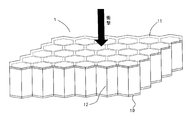
- FIG. 1 shows an impact absorbing device of this embodiment.
- the shock absorbing device 1 connects the opposing plate portion 10, the pressure receiving plate portion 11 disposed in parallel with the opposing plate portion 10 at an interval, and the opposing plate portion 10 and the pressure receiving plate portion 11. 10 and a pressure-sensitive plate portion 11 and a lattice-like rib 12 that divides a space into a plurality of small chambers.
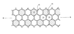
- the chambers formed by the opposing plate portion 10 and the pressure receiving plate portion 11 and the lattice-like ribs 12 each have a regular hexagonal cross section, and are formed in a honeycomb shape as a whole.
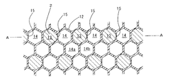
- the plurality of small chambers are composed of a filled chamber 13 filled with the enclosure 2 and an empty chamber 14 filled with the air without being filled with anything. Are respectively adjacent to the positions corresponding to the sides of the hexagonal section. Further, every other three ribs 12 out of the six ribs 12 that define the filling chamber 13, as shown in an enlarged view in FIG. Is formed.
- the thickness of the rib 12 is 1.8 mm, and the thickness of the thin portion 15 is 1.0 mm.
- the filling chamber 13 is filled and encapsulated with an enclosure 2 made of gel formed by water absorption of water-absorbent resin powder.
- the impact absorbing device 1 is made of a polyolefin-based resin. First, a member including a pressure receiving plate portion 11 and a rib 12 having a thin portion 15 is formed by injection molding, and an enclosure 2 is placed in a hollow portion corresponding to the filling chamber 13. It is manufactured by filling and then welding the opposing plate portion 10.
- the impact absorbing device 1 of the present embodiment is arranged and used so that an impact load acts on the pressure receiving plate portion 11 as shown in FIG.
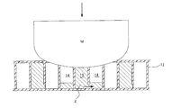
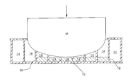
- the colliding object M contacts the pressure receiving plate portion 11 and presses the pressure receiving plate portion 11 toward the counter plate portion 10.
- FIG. 4 shows a cross section taken along the line AA of FIG.
- impact energy is absorbed by the deformation of the rib 12 and the compression of the enclosure 2.
- the impact energy is greater than the absorbed energy, as shown in FIG. 5, the impact object M is absorbed by the collision object M entering the impact absorbing device 1 and buckling the ribs 12 positioned below it.
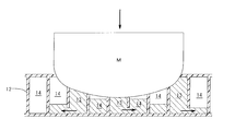
- the enclosure 2 flows into the empty chamber 14 from the filling chamber 13 through the fracture portion. Impact energy is also absorbed by the flow resistance generated at that time.
- the impact energy is absorbed by both the buckling of the rib 12 and the flow resistance of the inclusion body 2, and high impact absorption performance is exhibited.
- the impact energy is absorbed, the energy of the collision object M gradually decreases, but the contact area between the collision object M and the shock absorption device 1 increases, and the force applied per unit area of the shock absorption device 1 is increased. Decrease in acceleration. For this reason, it may be difficult to buckle the ribs 12 later in the shock absorption, and there is a concern about the spring back from the enclosure 2 enclosed in the filling chamber 13.
- the impact absorbing device 1 of the present embodiment As shown in FIG. 6, even if the collision object M further enters, the rib 12 to be buckled has already buckled and the thin portion 15 has already broken. Therefore, the impact energy can be absorbed by the flow resistance when the enclosure 2 flows from the broken thin portion 15 into the empty chamber 14. Further, by using a gel having an impact absorbing performance as the enclosure 2, the impact energy can be absorbed more effectively. Therefore, even if the force applied per unit area of the impact absorbing device 1 is small, it is possible to further absorb the impact energy and to delay the occurrence of the bottoming phenomenon.
- the enclosure 2 that has flowed into the empty chamber 14 from the broken thin portion 15 may be difficult to flow out of the enclosure 2.
- the empty chamber 14a shown in FIG. 2 allows the inclusion body 2 to flow from the adjacent filling chamber 13, but cannot flow out to another adjacent empty chamber 14b. Therefore, when the collision object M further invades and comes into contact with the enclosure 2 of the filling chamber 13 and the empty chamber 14 that communicate with each other through the broken thin portion 15, the enclosure 2 is compressed and the spring is compressed. There is concern about back.
- the shock absorbing device of the present embodiment has the second thin portion 16 formed on the rib 12 that divides the vacant chambers 14 adjacent to each other.
- the enclosure 2 is dispersed into the plurality of empty chambers 14 through the thinned portion 15 and the thinned portion 16 that are broken. Therefore, even when the collision object M further enters as shown in FIG. 8, the collision object M is delayed in contact with the liquid surface of the enclosure 2, and the enclosure 2 is delayed in compression. It is possible to further delay the occurrence of the bottoming phenomenon.
- FIG. 8 shows a BB cross section of FIG.
- the shock absorbing device of the present embodiment has the same configuration as that of the first embodiment except that the second thin portion 16 shown in FIG. 9 is formed at a portion of the counter plate portion 10 that faces the empty chamber 14.
- the shock absorbing device of the present embodiment when the thin wall portion 15 is broken and the empty chamber 14 is filled with the enclosure 2 and further compressed, the second thin wall portion 16 is broken and the broken portion is removed.
- the inclusion body 2 is discharged to the outside. Therefore, the bottoming phenomenon due to the inclusion body 2 can be eliminated.
- FIG. 10 shows a cross-sectional view of a main part of an automobile using the impact absorbing device of this embodiment.
- a reinforcement 101 is disposed integrally with the vehicle body.
- the impact absorbing device 200 of the present embodiment is disposed.
- the shock absorbing device 200 is formed by connecting a plurality of hexagonal columnar unit shock absorbing members 3, and the side surfaces of the unit shock absorbing members 3 are connected.
- the unit impact absorbing members 3 are arranged so as to extend in the longitudinal direction of the front bumper rod 100, respectively.
- Each unit shock absorbing member 3 includes a cylindrical portion 30 having a hexagonal cross section and a pair of end portions 31 which are joined to both ends of the cylindrical portion 30 and block the opening.
- the end portion 31 is a position where the six wall portions of the cylindrical portion 30 protrude outward in the longitudinal direction from the opening and extend toward the center of the shaft, and the cross-section is gradually reduced to be separated from the cylindrical portion 30 by a predetermined distance. In this way, each wall portion joins one point to block the opening. Therefore, a sealed hollow portion is formed inside the unit impact absorbing member 3.
- the cylinder part 30 is formed by extrusion molding from a polyolefin resin. Further, the end portion 31 is formed by press molding from a polyolefin-based resin, and the unit impact absorbing member 3 is formed by being welded to both ends of the cylindrical portion 30.
- each unit impact absorbing member 3 is filled with an enclosure 2 made of gel formed by absorbing water of the water-absorbent resin powder.
- a pressure receiving plate portion 32 is formed on the cylinder portion 30 of the unit impact absorbing member 3 on the side facing the front bumper rod 100, and on the side facing the reinforcement rod 101, the pressure receiving plate portion 32 is formed. And an opposing plate portion 33 that is opposed in parallel with a gap therebetween.
- a small-diameter through hole 34 that connects the hollow portion and the outside is formed in the wall portion adjacent to the lower side of the opposed plate portion 33, and a plurality of through holes 34 are formed at intervals in the longitudinal direction of the cylindrical portion 30.
- the enclosure 2 Since the enclosure 2 is in the form of a gel, it does not leak from the through-hole 34 as it is, but in order to prevent moisture from evaporating from the enclosure 2, the through-hole 34 is sealed from a polyethylene film from the outside. Covered with.
- the impact absorbing device 200 of the present embodiment acts as follows to absorb the impact.
- the front bumper rod 100 When an impact is applied to the front bumper rod 100 as shown by the arrows in FIGS. 10 and 12, the front bumper rod 100 is deformed in a direction approaching the reinforcement rod 101, and the stress is transmitted to the shock absorbing device 200. That is, the impact force is first transmitted from the pressure receiving plate portion 32 to the unit shock absorbing member 3 and tends to deform in the direction in which the pressure receiving plate portion 32 approaches the counter plate portion 33.
- the pressure receiving plate portion 32 When a relatively strong impact energy is applied to the pressure receiving plate portion 32, the pressure receiving plate portion 32 is deformed in the direction approaching the opposing plate portion 13 to reduce the volume of the hollow portion, and the internal pressure of the enclosure 2 is reduced by the compression. Rise. The internal pressure is transmitted from the through hole 34 to the sealing material 35. When the internal pressure exceeds a predetermined value, the sealing material 35 is broken and the through hole 34 is opened. As a result, the enclosure 2 flows out from the through hole 34, and the pressure receiving plate portion 32 further approaches the counter plate portion 33. When the enclosure 2 passes through the through-hole 34, a large resistance force is generated, and this resistance force continues while the volume of the hollow portion is reduced. That is, the impact energy is absorbed by the deformation of the cylindrical portion 30 and the enclosure 2 and is absorbed mainly by the resistance force when the enclosure 2 passes through the through hole 34.
- the spring back by the enclosure 2 does not act, and the impact energy is absorbed mainly by the resistance when the enclosure 2 passes through the through hole 34. Can be absorbed.
- the pressure receiving plate part 32 and the counter plate part 33 are finally formed. It will be in contact. Therefore, since the impact energy is absorbed until the pressure receiving plate portion 32 comes into contact with the counter plate portion 33, the distance between the pressure receiving plate portion 32 and the counter plate portion 33 becomes the shock absorbing stroke, and the front bumper rod 100 and the reinforcement Even if the interval with 101 is short, the entire interval can be used for shock absorption. In other words, even in a small arrangement space, sufficient shock absorbing performance is exhibited.
- Example 5 In Example 4, the unit shock absorbing members 3 are connected in a single layer, but a multi-layer structure of two or more layers may be used as shown in FIG. Further, depending on the magnitude of the impact energy, it is possible to absorb the impact with only one unit impact absorbing member 3.
- FIG. 14 shows a cross-sectional view of the unit shock absorbing member 4 according to this embodiment.
- an outer cylinder 40 having a hexagonal cross section is integrally disposed on the outer periphery of the cylindrical portion 30 of the unit impact absorbing member 3 of the fourth embodiment.
- the opposing wall portion 41 facing the reinforcement 101 of the outer cylinder 40 also serves as the opposing plate portion 33 of the cylindrical portion 30 and further extends the opposing plate portion 33 in the vertical direction, and the other five wall portions are Each faces the surface of the outer cylinder 40 with a predetermined distance.
- a space 42 having a substantially C-shaped cross section is formed between the outer peripheral surface of the cylindrical portion 30 and the inner peripheral surface of the outer cylinder 40. Further, the outer cylinder 40 is not formed with a through-hole communicating between the inside and the outside.
- the unit impact absorbing member 4 is arranged so that an impact acts on the pressure receiving wall portion 43 facing the pressure receiving plate portion 32 of the cylindrical portion 30. At the time of impact absorption, the pressure receiving wall portion 43 presses the pressure receiving plate portion 32 due to the deformation of the outer cylinder 40, and the pressure receiving plate portion 32 approaches the counter plate portion 33 as in the fourth embodiment. And the enclosure 2 flows out from the through-hole 34, and impact energy is absorbed by the resistance.
- the enclosure 2 that has flowed out of the through hole 34 at the time of absorbing the shock flows into the space 42 and does not flow out of the space 42 to the outside. Therefore, the degree of freedom in selecting the material of the enclosure 2 is improved.
- the cylindrical portion 30 is deformed in the same manner as in the fourth embodiment so that the pressure receiving plate portion 32, the opposing plate portion 33, and the opposing wall portion 41 are in contact with each other, and the pressure receiving wall portion 43 is in contact with the pressure receiving plate portion 32. Therefore, since the distance between the pressure receiving wall portion 43 and the counter plate portion 33 is an impact absorbing stroke, even if the interval between the front bumper 100 and the reinforcement 101 is short, the entire interval can be used for absorbing the impact.
- the unit impact absorbing member 5 has a cylindrical portion 50 having a parallelogram cross section, an opposing plate portion 52 on the side facing the pressure receiving plate portion 51 that receives an impact, and an opposing plate. A through hole 53 is formed in the portion 52.
- the cylindrical body 50 is filled with the enclosure 2 as in the fourth embodiment.
- the cylindrical portion 50 is deformed so that the pair of inclined side plates are inclined in the acute angle direction, and the pressure receiving plate portion 51 and the counter plate portion 52 eventually overlap. Therefore, the distance between the pressure receiving plate portion 51 and the counter plate portion 52 is the shock absorbing stroke.
- the unit impact absorbing member 6 As shown in FIG. 16, the unit impact absorbing member 6 according to the present embodiment has a cylindrical portion 60 having an elliptical cross section, and constitutes a pressure receiving plate portion 61 on which one arc surface on the short axis side receives an impact. The other arc surface on the side constitutes the counter plate portion 62. A through hole 63 is formed in the opposing plate portion 62. The inside of the cylindrical portion 60 is filled with the enclosure 2 as in the fourth embodiment.
- the cylindrical portion 60 is deformed so that the minor axis of the cross-sectional ellipse is shorter and the major axis is longer, and finally the pressure receiving plate portion 61 and the opposing plate portion 62 Overlap. Therefore, the distance between the pressure receiving plate portion 61 and the counter plate portion 62 is the shock absorbing stroke.
- the cylindrical portion 60 may have a shape in which a hollow portion having the largest interval is formed. In this way, it can be deformed with a smaller impact energy than the cylindrical section 60 having an elliptical cross section.
- the unit shock absorbing member 7 has a cylindrical portion 70 having an inverted trapezoidal cross section, and the upper bottom constitutes a pressure receiving plate portion 71 that receives an impact, and the lower bottom is a counter plate portion. 72 is composed. A through hole 73 is formed in the counter plate portion 72.
- the cylindrical body 70 is filled with the enclosure 2 as in the fourth embodiment.
- both ends of the pressure receiving plate portion 71 in the width direction are in contact with the inside of the pair of side plates 74, and when the pressure receiving plate portion 71 moves in a direction close to the opposing plate portion 72 due to an impact, the pair of side plates 74 are respectively The pressure receiving plate portion 71 and the opposing plate portion 72 are finally overlapped by pressing outward. Therefore, the distance between the pressure receiving plate portion 71 and the opposing plate portion 72 is the shock absorbing stroke.
- the unit impact absorbing member 8 has a cylindrical portion 80 having a substantially continuous cross section.
- the cylindrical portion 80 includes an upper drum portion 81 and a lower drum portion 82 that are parallel to each other, and a pair of throttle portions 83 that connect the upper drum portion 81 and the lower drum portion 82, and the central portion of the throttle portion 83 is a hollow portion. It has entered.
- the upper drum portion 81 constitutes a pressure receiving plate portion that receives an impact
- the lower drum portion 82 constitutes a counter plate portion.
- a through hole 84 is formed in the lower drum portion 82.
- the throttle portion 83 is deformed so that the center portion enters further into the hollow portion, and finally the upper drum portion at both ends.
- the two plates of the part 81 and the diaphragm part 83 and the lower drum part 82 overlap. Therefore, a value obtained by subtracting the thicknesses of the two plates of the diaphragm portion 83 from the distance between the upper drum portion 81 and the drum portion 82 is the shock absorption stroke.
Landscapes
- Engineering & Computer Science (AREA)
- Mechanical Engineering (AREA)
- General Engineering & Computer Science (AREA)
- Textile Engineering (AREA)
- Vibration Dampers (AREA)
- Fluid-Damping Devices (AREA)
Abstract
Description
10:対向板部 11:受圧板部 12:リブ
13:充填小室 14:空小室 15:薄肉部(脆弱部)
3:単位衝撃吸収部材 32:受圧板部
33:対向板部 34:貫通孔
図1に本実施例の衝撃吸収装置を示す。この衝撃吸収装置1は、対向板部10と、対向板部10と間隔を隔てて平行に配置された受圧板部11と、対向板部10及び受圧板部11を連結するとともに、対向板部10及び受圧板部11の間に形成された空間を複数の小室に区画する格子状のリブ12とから構成されている。対向板部10及び受圧板部11と、格子状のリブ12とで形成された小室はそれぞれ断面正六角形をなし、全体としてハニカム状に形成されている。
しかし実施例1の衝撃吸収装置1においては、破断した薄肉部15から空小室14に流入した封入体2は、封入体2から流出することが困難となる場合がある。例えば図2に示す空小室14a は、隣接する充填小室13からの封入体2の流入は許容するものの、隣接する他の空小室14b などへ流出することはできない。そのため衝突物Mがさらに侵入し、破断した薄肉部15を介して互いに連通する充填小室13と空小室14の封入体2に当接した場合には、封入体2が圧縮されることになりスプリングバックが懸念される。
本実施例の衝撃吸収装置は、対向板部10の空小室14に対向する部位に、図9に示す第2の薄肉部16を形成したこと以外は実施例1と同様の構成である。
図10に本実施例の衝撃吸収装置を用いた自動車の要部断面図を示す。フロントバンパ 100の内部には、リインホースメント 101が車体と一体となって配置されている。フロントバンパ 100とリインホースメント 101との間に、本実施例の衝撃吸収装置 200が配置されている。
実施例4では、単位衝撃吸収部材3を一層となるように連結しているが、図13に示すように二層以上の複層構造とすることもできる。また衝撃エネルギーの大きさによっては、一つの単位衝撃吸収部材3のみで衝撃吸収することも可能である。
図14に本実施例に係る単位衝撃吸収部材4の断面図を示す。この単位衝撃吸収部材4は、実施例4の単位衝撃吸収部材3の筒部30の外周に断面六角形の外筒40を一体的に配置している。外筒40のリインホースメント 101に対向する対向壁部41は、筒部30の対向板部33を兼ねるとともに対向板部33を上下方向にさらに延長した形状をなし、他の五つの壁部はそれぞれ外筒40の表面に所定距離を隔てて対向している。
(実施例7)
本実施例に係る単位衝撃吸収部材5は、図15に示すように断面平行四辺形の筒部50をもち、衝撃を受ける受圧板部51に対向する側に対向板部52をもち、対向板部52に貫通孔53が形成されている。筒部50の内部には実施例4と同様に封入体2が充填されている。
本実施例に係る単位衝撃吸収部材6は、図16に示すように断面楕円形の筒部60をもち、短軸側の一方の円弧面が衝撃を受ける受圧板部61を構成し、短軸側の他方の円弧面が対向板部62を構成している。対向板部62に貫通孔63が形成されている。筒部60の内部には実施例4と同様に封入体2が充填されている。
本実施例に係る単位衝撃吸収部材7は、図18に示すように、断面逆台形をなす筒部70をもち、上底が衝撃を受ける受圧板部71を構成し、下底が対向板部72を構成している。対向板部72に貫通孔73が形成されている。筒部70の内部には実施例4と同様に封入体2が充填されている。
本実施例に係る単位衝撃吸収部材8は、図19に示すように、断面略つづみ状をなす筒部80をもつ。筒部80は、互いに平行な上太鼓部81及び下太鼓部82と、上太鼓部81及び下太鼓部82を連結する一対の絞り部83とからなり、絞り部83は中央部が中空部に入り込んでいる。上太鼓部81が衝撃を受ける受圧板部を構成し、下太鼓部82が対向板部を構成している。下太鼓部82に貫通孔84が形成されている。
Claims (14)
- 衝撃が加わる受圧板部と、該受圧板部と間隔を隔てて対向する対向板部と、該受圧板部と該対向板部を連結するとともに該受圧板部と該対向板部の間を複数の小室に区画する格子状のリブと、を備えてなり、
複数の該小室は、液体を主成分とする封入体が充填された充填小室と、大気が充填された空小室とからなり、該充填小室には少なくとも一つの該空小室が隣接し、該充填小室と隣接する該空小室とを区画する該リブの少なくとも一つには脆弱部が形成され、
該受圧板部と該対向板部を互いに近接させる方向へ衝撃が加わったときに、該リブが座屈することで衝撃エネルギーを吸収するとともに該封入体が圧縮されることで衝撃エネルギーを吸収し、該脆弱部が破断した後は該充填小室から該空小室へ流入する該封入体の流通抵抗によってさらに衝撃エネルギーを吸収することを特徴とする衝撃吸収装置。 - 前記空小室に隣接する第2の前記空小室をもち、前記空小室と隣接する第2の前記空小室とを区画する前記リブにも脆弱部が形成されている請求の範囲第1項に記載の衝撃吸収装置。
- 前記充填小室には複数の前記空小室のみが隣接している請求の範囲第1項に記載の衝撃吸収装置。
- 前記充填小室及び前記空小室は、断面正六角形の筒状をなす請求の範囲第1~3項のいずれかに記載の衝撃吸収装置。
- 前記脆弱部は薄肉部である請求の範囲第1~4項のいずれかに記載の衝撃吸収装置。
- 前記脆弱部は、前記受圧板部と前記対向板部のうち一方の近傍に形成されている請求の範囲第1~5項のいずれかに記載の衝撃吸収装置。
- 前記封入体はゲル状体である請求の範囲第1~6項のいずれかに記載の衝撃吸収装置。
- 板状の外壁部で囲まれた中空部をもつ本体と、該中空部に充填され液体を主成分とする封入体と、該中空部と外部とを連通するように該本体に設けられ該本体に加わる衝撃の力により該封入体を徐々に外部へ排出する貫通孔とからなり、該封入体が該貫通孔を通過する際の抵抗により衝撃を吸収するように構成された衝撃吸収装置であって、
該本体は、衝撃が加わる受圧板部と、該受圧板部と間隔を隔てて対向する対向板部とを有し、該中空部内に突出するリブ又は該中空部を区画するリブをもたず、衝撃により該受圧板部と該対向板部とが互いに近接する方向へ変形して該受圧板部が該対向板部に限りなく近接することを特徴とする衝撃吸収装置。 - 前記本体は、前記受圧板部と前記対向板部とを含む複数の板部材から構成され、全ての該板部材が前記中空部内に向かって入り込んでいない請求の範囲第8項に記載の衝撃吸収装置。
- 前記本体は、断面における各辺の数が6以上の偶数である多角形形状をなし、断面で互いに対向する平行な2辺をそれぞれ含む一対の面が前記受圧板部と前記対向板部を構成する請求の範囲第9項に記載の衝撃吸収装置。
- 前記本体は、断面が平行四辺形をなす請求の範囲第9項に記載の衝撃吸収装置。
- 前記本体は、断面が楕円形状をなす請求の範囲第9項に記載の衝撃吸収装置。
- 前記本体が前記受圧板部及び前記対向板部と垂直方向に複数個積層されてなる請求の範囲第8~12項のいずれかに記載の衝撃吸収装置。
- 前記封入体はゲル状体である請求の範囲第8~13項のいずれかに記載の衝撃吸収装置。
Priority Applications (3)
| Application Number | Priority Date | Filing Date | Title |
|---|---|---|---|
| JP2009552438A JP5170112B2 (ja) | 2008-02-04 | 2009-01-27 | 衝撃吸収装置 |
| CN200980104103XA CN101939558B (zh) | 2008-02-04 | 2009-01-27 | 冲击吸收装置 |
| US12/735,508 US8596432B2 (en) | 2008-02-04 | 2009-01-27 | Shock absorbing apparatus |
Applications Claiming Priority (4)
| Application Number | Priority Date | Filing Date | Title |
|---|---|---|---|
| JP2008023932 | 2008-02-04 | ||
| JP2008-023932 | 2008-02-04 | ||
| JP2008-036303 | 2008-02-18 | ||
| JP2008036303 | 2008-02-18 |
Publications (1)
| Publication Number | Publication Date |
|---|---|
| WO2009098971A1 true WO2009098971A1 (ja) | 2009-08-13 |
Family
ID=40952049
Family Applications (1)
| Application Number | Title | Priority Date | Filing Date |
|---|---|---|---|
| PCT/JP2009/051270 Ceased WO2009098971A1 (ja) | 2008-02-04 | 2009-01-27 | 衝撃吸収装置 |
Country Status (4)
| Country | Link |
|---|---|
| US (1) | US8596432B2 (ja) |
| JP (1) | JP5170112B2 (ja) |
| CN (1) | CN101939558B (ja) |
| WO (1) | WO2009098971A1 (ja) |
Cited By (7)
| Publication number | Priority date | Publication date | Assignee | Title |
|---|---|---|---|---|
| CN103069078A (zh) * | 2010-08-11 | 2013-04-24 | 新都产业株式会社 | 冲击吸收装置 |
| JP2014181758A (ja) * | 2013-03-19 | 2014-09-29 | Nissan Motor Co Ltd | 衝撃吸収体 |
| JP2014184899A (ja) * | 2013-03-25 | 2014-10-02 | Toyota Auto Body Co Ltd | 衝撃吸収部材 |
| JP2015087324A (ja) * | 2013-10-31 | 2015-05-07 | 三菱重工業株式会社 | 放射性物質収納容器支持架台 |
| JP2019034517A (ja) * | 2017-08-21 | 2019-03-07 | 株式会社荒井製作所 | ハニカム構造体及びハニカム構造体成形用金型 |
| JP2020183201A (ja) * | 2019-05-09 | 2020-11-12 | トヨタ車体株式会社 | 衝撃吸収部材 |
| US20220097499A1 (en) * | 2020-09-25 | 2022-03-31 | Brose Fahrzeugteile SE & Co. Kommanditgesellschaft, Coburg | Component provided for energy absorption |
Families Citing this family (22)
| Publication number | Priority date | Publication date | Assignee | Title |
|---|---|---|---|---|
| CN102205822B (zh) * | 2011-05-23 | 2013-12-11 | 清华大学 | 一种吸能型汽车保险杠 |
| CN102975674A (zh) * | 2011-09-02 | 2013-03-20 | 浩华科技实业有限公司 | 剪切增稠液汽车保险杠 |
| CN102829119B (zh) * | 2012-08-24 | 2014-05-28 | 西北核技术研究所 | 一种级联式载荷缓冲吸能装置 |
| GB201221064D0 (en) * | 2012-11-23 | 2013-01-09 | Secr Defence | A deformable element |
| JP6308437B2 (ja) * | 2012-12-18 | 2018-04-11 | 東レ株式会社 | 締結部構造 |
| US9067550B2 (en) * | 2013-01-18 | 2015-06-30 | Sabic Global Technologies B.V. | Polymer, energy absorber rail extension, methods of making and vehicles using the same |
| US8864216B2 (en) | 2013-01-18 | 2014-10-21 | Sabic Global Technologies B.V. | Reinforced body in white and method of making and using the same |
| CN104085365A (zh) * | 2013-04-01 | 2014-10-08 | 陈曦 | 一种基于纳米多孔能量吸收材料的汽车保险杠 |
| CN106458131A (zh) | 2014-06-16 | 2017-02-22 | 沙特基础工业全球技术有限公司 | 制备层压板的方法、吸能装置、吸能装置组合物及成形工具 |
| CN106573586B (zh) | 2014-07-25 | 2020-07-10 | 沙特基础工业全球技术有限公司 | 可压碎聚合物纵梁延伸件、系统及其制作和使用方法 |
| JP6156291B2 (ja) * | 2014-09-01 | 2017-07-05 | トヨタ自動車株式会社 | 車両用ドア構造 |
| KR101625330B1 (ko) | 2015-04-23 | 2016-06-07 | 최석진 | 충격 흡수용 안전 범퍼 |
| US10647283B2 (en) * | 2015-11-27 | 2020-05-12 | Kyoraku Co., Ltd. | Shock absorber |
| CN105857223A (zh) * | 2016-04-17 | 2016-08-17 | 王福成 | 高强度防撞钢梁 |
| CN106080470A (zh) * | 2016-08-29 | 2016-11-09 | 芜湖常瑞汽车部件有限公司 | 汽车吸能防撞梁 |
| GB2587077B (en) * | 2017-11-24 | 2022-07-06 | Dhanya R S | Collision impact reducer |
| CN108791113B (zh) * | 2018-06-14 | 2020-07-03 | 吉林大学 | 具有低峰值吸能结构的高集成一体化汽车顶棚 |
| US20210135177A1 (en) * | 2019-11-05 | 2021-05-06 | Ford Global Technologies, Llc | Energy absorbing structures for traction battery packs |
| CN112922991B (zh) * | 2019-12-06 | 2022-02-18 | 同济大学 | 基于相嵌小半周界面结构的复合吸能结构 |
| CN111237373A (zh) * | 2020-01-23 | 2020-06-05 | 哈尔滨工业大学 | 新型变强度蜂窝结构、其制作装置及其制作方法 |
| CN112943834B (zh) * | 2021-01-29 | 2022-08-02 | 华中科技大学 | 一种正负泊松比循环杂交抗冲吸能结构及其应用 |
| CN114962511B (zh) * | 2022-06-07 | 2023-04-21 | 江苏科技大学 | 一种含剪切增稠液的双管薄壁吸能结构及其制备方法 |
Citations (6)
| Publication number | Priority date | Publication date | Assignee | Title |
|---|---|---|---|---|
| JP2001132787A (ja) * | 1999-11-01 | 2001-05-18 | Tokai Rubber Ind Ltd | 衝撃吸収部材 |
| JP2004360790A (ja) * | 2003-06-04 | 2004-12-24 | Jsp Corp | エネルギー吸収部材 |
| WO2005003588A1 (ja) * | 2003-07-01 | 2005-01-13 | Honda Motor Co., Ltd. | 輸送機械用骨格構造部材 |
| JP2005022514A (ja) * | 2003-07-01 | 2005-01-27 | Honda Motor Co Ltd | 輸送機械用骨格構造部材 |
| JP2005053438A (ja) * | 2003-08-07 | 2005-03-03 | Kobe Steel Ltd | 対人保護エネルギー吸収部材用アルミニウム合金中空形材 |
| JP2007024084A (ja) * | 2005-07-12 | 2007-02-01 | Nissan Motor Co Ltd | Mdb試験に用いる衝撃吸収体およびその衝撃吸収体の形成方法 |
Family Cites Families (22)
| Publication number | Priority date | Publication date | Assignee | Title |
|---|---|---|---|---|
| FR2288648A1 (fr) * | 1974-03-05 | 1976-05-21 | Peugeot & Renault | Pare-chocs composite absorbeur d'energie |
| FR2629162B1 (fr) * | 1988-03-25 | 1993-10-08 | Ecole Nale Superieure Meca | Dispositif absorbeur de choc |
| DE3925821A1 (de) * | 1989-08-04 | 1990-08-30 | Daimler Benz Ag | Mit einem energieabsorbierenden schaum angefuellter energieabsorber |
| US5026111A (en) * | 1989-10-16 | 1991-06-25 | Excel Industries, Inc. | Vehicle door structure with improved energy absorption characteristics |
| US5098124A (en) * | 1990-09-06 | 1992-03-24 | Automotive Technologies International Inc. | Padding to reduce injuries in automobile accidents |
| US5303843A (en) * | 1990-10-09 | 1994-04-19 | Montana Sulphur & Chemical Co. | Fluid transport apparatus with water hammer eliminator system |
| US5141279A (en) * | 1991-09-23 | 1992-08-25 | Davidson Textron Inc. | Side impact protection apparatus |
| US5356177A (en) * | 1993-06-25 | 1994-10-18 | Davidson Textron Inc. | Side impact protection apparatus |
| US5564535A (en) * | 1995-03-28 | 1996-10-15 | United States Of America | Side impact energy absorber |
| PT859919E (pt) * | 1995-11-06 | 2003-09-30 | Europ Economic Community | Aparelho de absorcao de energia |
| JP2990057B2 (ja) * | 1996-03-13 | 1999-12-13 | アイシン軽金属株式会社 | 車体側部のエネルギー吸収構造 |
| JPH09254727A (ja) | 1996-03-25 | 1997-09-30 | Toyoda Gosei Co Ltd | 衝撃吸収装置 |
| JPH11139341A (ja) | 1997-11-13 | 1999-05-25 | Toyoda Gosei Co Ltd | 衝撃吸収材 |
| JPH11286822A (ja) * | 1998-04-06 | 1999-10-19 | Jatco Corp | ヘルメットの緩衝構造 |
| US6148970A (en) * | 1998-04-24 | 2000-11-21 | Akad; Osman E. | Energy absorbing device |
| JP2000272447A (ja) | 1999-03-25 | 2000-10-03 | Toyoda Gosei Co Ltd | 自動車用衝撃吸収構造 |
| DE19945091A1 (de) * | 1999-09-21 | 2001-04-19 | Bosch Gmbh Robert | Antriebswelle für einen Scheibenwischer |
| US6234526B1 (en) * | 1999-09-27 | 2001-05-22 | Daimlerchrysler Corporation | Head impact protection using fluid viscosity |
| US7056564B2 (en) * | 2000-08-08 | 2006-06-06 | Sereboff Joel L | Gel filled trauma mitigation device and composition therefore |
| JP3888630B2 (ja) * | 2002-12-04 | 2007-03-07 | 川崎重工業株式会社 | エネルギー吸収部材及びそれを用いるヘリコプタの耐衝撃構造 |
| US7350851B2 (en) * | 2005-03-08 | 2008-04-01 | Gm Global Technology Operations, Inc. | Reversibly expandable energy absorbing assembly and methods for operating the same |
| JP5272950B2 (ja) * | 2009-07-29 | 2013-08-28 | 豊田合成株式会社 | 衝撃吸収部材 |
-
2009
- 2009-01-27 US US12/735,508 patent/US8596432B2/en not_active Expired - Fee Related
- 2009-01-27 CN CN200980104103XA patent/CN101939558B/zh not_active Expired - Fee Related
- 2009-01-27 JP JP2009552438A patent/JP5170112B2/ja not_active Expired - Fee Related
- 2009-01-27 WO PCT/JP2009/051270 patent/WO2009098971A1/ja not_active Ceased
Patent Citations (6)
| Publication number | Priority date | Publication date | Assignee | Title |
|---|---|---|---|---|
| JP2001132787A (ja) * | 1999-11-01 | 2001-05-18 | Tokai Rubber Ind Ltd | 衝撃吸収部材 |
| JP2004360790A (ja) * | 2003-06-04 | 2004-12-24 | Jsp Corp | エネルギー吸収部材 |
| WO2005003588A1 (ja) * | 2003-07-01 | 2005-01-13 | Honda Motor Co., Ltd. | 輸送機械用骨格構造部材 |
| JP2005022514A (ja) * | 2003-07-01 | 2005-01-27 | Honda Motor Co Ltd | 輸送機械用骨格構造部材 |
| JP2005053438A (ja) * | 2003-08-07 | 2005-03-03 | Kobe Steel Ltd | 対人保護エネルギー吸収部材用アルミニウム合金中空形材 |
| JP2007024084A (ja) * | 2005-07-12 | 2007-02-01 | Nissan Motor Co Ltd | Mdb試験に用いる衝撃吸収体およびその衝撃吸収体の形成方法 |
Cited By (9)
| Publication number | Priority date | Publication date | Assignee | Title |
|---|---|---|---|---|
| CN103069078A (zh) * | 2010-08-11 | 2013-04-24 | 新都产业株式会社 | 冲击吸收装置 |
| CN103069078B (zh) * | 2010-08-11 | 2016-08-17 | 新都产业株式会社 | 冲击吸收装置 |
| JP2014181758A (ja) * | 2013-03-19 | 2014-09-29 | Nissan Motor Co Ltd | 衝撃吸収体 |
| JP2014184899A (ja) * | 2013-03-25 | 2014-10-02 | Toyota Auto Body Co Ltd | 衝撃吸収部材 |
| JP2015087324A (ja) * | 2013-10-31 | 2015-05-07 | 三菱重工業株式会社 | 放射性物質収納容器支持架台 |
| JP2019034517A (ja) * | 2017-08-21 | 2019-03-07 | 株式会社荒井製作所 | ハニカム構造体及びハニカム構造体成形用金型 |
| JP2020183201A (ja) * | 2019-05-09 | 2020-11-12 | トヨタ車体株式会社 | 衝撃吸収部材 |
| JP7176473B2 (ja) | 2019-05-09 | 2022-11-22 | トヨタ車体株式会社 | 衝撃吸収部材 |
| US20220097499A1 (en) * | 2020-09-25 | 2022-03-31 | Brose Fahrzeugteile SE & Co. Kommanditgesellschaft, Coburg | Component provided for energy absorption |
Also Published As
| Publication number | Publication date |
|---|---|
| CN101939558A (zh) | 2011-01-05 |
| US20100300824A1 (en) | 2010-12-02 |
| JP5170112B2 (ja) | 2013-03-27 |
| CN101939558B (zh) | 2013-02-13 |
| JPWO2009098971A1 (ja) | 2011-05-26 |
| US8596432B2 (en) | 2013-12-03 |
Similar Documents
| Publication | Publication Date | Title |
|---|---|---|
| JP5170112B2 (ja) | 衝撃吸収装置 | |
| CN103228488B (zh) | 汽车的前部结构 | |
| US6135252A (en) | Shock isolator and absorber apparatus | |
| US11077885B2 (en) | Rocker member and vehicle | |
| CN106828381B (zh) | 一种基于多稳态单胞结构的多级安全防撞梁总成 | |
| EP3778343B1 (en) | Reusable collision energy absorption device for rail vehicle | |
| US4257581A (en) | Impact absorbing strut | |
| CN116729443B (zh) | 一种液压剪断导向式防爬吸能装置 | |
| US7513564B2 (en) | Skeleton structural member for transportation equipment | |
| CN111646016B (zh) | 一种管型材料运输缓冲支架装置 | |
| US6148970A (en) | Energy absorbing device | |
| WO2014126183A1 (ja) | エネルギー吸収部材 | |
| CN104842906A (zh) | 吸能缓冲装置、防撞结构和车辆 | |
| CN101413560A (zh) | 阵列式金属杯形薄壁结构吸能器 | |
| CN220262712U (zh) | 一种新能源汽车前防撞梁 | |
| JP2002257173A (ja) | ショックアブソーバ | |
| CN214057445U (zh) | 防撞梁和车辆 | |
| KR200238804Y1 (ko) | 차량용 범퍼 | |
| CN113882239A (zh) | 一种自复位多级变刚度粘滞阻尼器 | |
| CN116104552B (zh) | 立柱及支护系统 | |
| EP3112653A1 (en) | Fluid duct | |
| CN216401367U (zh) | 一种吸能辅助装置及车辆 | |
| CN222538769U (zh) | 一种防撞梁和车辆 | |
| GB2384218A (en) | A bumper assembly for a motor vehicle | |
| KR20160064619A (ko) | 차량용 경량 크래쉬박스 |
Legal Events
| Date | Code | Title | Description |
|---|---|---|---|
| WWE | Wipo information: entry into national phase |
Ref document number: 200980104103.X Country of ref document: CN |
|
| 121 | Ep: the epo has been informed by wipo that ep was designated in this application |
Ref document number: 09708031 Country of ref document: EP Kind code of ref document: A1 |
|
| WWE | Wipo information: entry into national phase |
Ref document number: 2009552438 Country of ref document: JP |
|
| WWE | Wipo information: entry into national phase |
Ref document number: 12735508 Country of ref document: US |
|
| NENP | Non-entry into the national phase |
Ref country code: DE |
|
| 122 | Ep: pct application non-entry in european phase |
Ref document number: 09708031 Country of ref document: EP Kind code of ref document: A1 |