WO2009098926A1 - スピーカならびにマグネット部品およびその製造方法 - Google Patents
スピーカならびにマグネット部品およびその製造方法 Download PDFInfo
- Publication number
- WO2009098926A1 WO2009098926A1 PCT/JP2009/050553 JP2009050553W WO2009098926A1 WO 2009098926 A1 WO2009098926 A1 WO 2009098926A1 JP 2009050553 W JP2009050553 W JP 2009050553W WO 2009098926 A1 WO2009098926 A1 WO 2009098926A1
- Authority
- WO
- WIPO (PCT)
- Prior art keywords
- magnet
- yoke
- resin
- bonded
- manufacturing
- Prior art date
- Legal status (The legal status is an assumption and is not a legal conclusion. Google has not performed a legal analysis and makes no representation as to the accuracy of the status listed.)
- Ceased
Links
Images



Classifications
-
- H—ELECTRICITY
- H04—ELECTRIC COMMUNICATION TECHNIQUE
- H04R—LOUDSPEAKERS, MICROPHONES, GRAMOPHONE PICK-UPS OR LIKE ACOUSTIC ELECTROMECHANICAL TRANSDUCERS; ELECTRIC HEARING AIDS; PUBLIC ADDRESS SYSTEMS
- H04R1/00—Details of transducers, loudspeakers or microphones
- H04R1/02—Casings; Cabinets ; Supports therefor; Mountings therein
-
- H—ELECTRICITY
- H04—ELECTRIC COMMUNICATION TECHNIQUE
- H04R—LOUDSPEAKERS, MICROPHONES, GRAMOPHONE PICK-UPS OR LIKE ACOUSTIC ELECTROMECHANICAL TRANSDUCERS; ELECTRIC HEARING AIDS; PUBLIC ADDRESS SYSTEMS
- H04R31/00—Apparatus or processes specially adapted for the manufacture of transducers or diaphragms therefor
Definitions
- the present invention relates to a speaker, and more particularly, for example, a magnet and a yoke that houses the magnet, and a coil wound in a plate shape disposed above a gap between the magnet outer periphery and the yoke inner periphery (the conductor is orthogonal to the winding axis). It is related with a speaker provided with the thing wound in the surface direction to do: a horizontal coil.
- Patent Document 1 An example of this type of speaker is disclosed in Patent Document 1.
- a fixing member made of a nonmagnetic material is fitted into the gap.
- Patent Document 2 Another example is disclosed in Patent Document 2.
- the gap is filled with resin.
- JP 2006-86942 A [H04R 9/02, 9/00]
- JP 2006-94269 A [H04R 9/00, 7/04, 9/02, 31/00]
- the magnet in order to obtain a uniform and high magnetic flux density at the coil position, it is particularly preferable to arrange the magnet accurately at the center of the yoke and to secure an optimum width gap between the outer circumference of the magnet and the inner circumference of the yoke. Desired. This is because when the horizontal coil is placed above the gap, the vibration of the diaphragm when the magnetic flux distribution becomes non-uniform due to the deviation of the magnet position and the gap size accuracy is less than when the cylindrical coil is placed in the gap. This is because the sound quality is degraded even if a slight positional deviation or insufficient accuracy occurs.
- FIG. 6 shows an example of the relationship between the gap width and the magnetic flux density at the horizontal coil position above the gap for this type of speaker.
- the horizontal axis indicates the distance (0 to 1 mm) from one end of the horizontal coil to the other end
- the vertical axis indicates the magnetic flux density. From four curves corresponding to four types of gap widths (no gap, 0.1 mm, 0.2 mm and 0.3 mm), the optimum gap width is 0.2 mm. It turns out that it falls.
- Patent Document 1 there is another problem that, when assembling, an operator attaches a fixing member to a magnet and attaches the magnet with the fixing member to the yoke, so that the amount of work is large.
- a main object of the present invention is to provide a novel speaker and magnet component and a method for manufacturing the same.
- Another object of the present invention is to provide a speaker using a horizontal coil wound in the form of a plate, which can obtain a uniform and high magnetic flux density above the gap, and the amount of work during assembly used in such a speaker. It is an object of the present invention to provide a magnet part and a manufacturing method thereof that can be reduced.
- This invention employs the following configuration in order to solve the above problems.
- reference numerals in parentheses, supplementary explanations, and the like indicate correspondence with embodiments to be described later in order to help understanding of the present invention, and do not limit the present invention.
- the speaker according to the first invention is a magnet, a yoke that is magnetically coupled to the magnet, and is interposed between the magnet and the yoke so that one part is bonded to the magnet in an adhesive state and the other part is not bonded to the yoke. And a horizontal coil wound above the resin member and supplied with a current according to an audio signal, and a diaphragm mechanically coupled to the horizontal coil.
- the resin member (14) is interposed between the magnet (12) and the yoke (16).
- a horizontal coil (22) mechanically coupled to the diaphragm (20) is disposed above the resin member, and a current according to the audio signal is supplied to the horizontal coil.
- the magnetic flux density at the coil position varies depending on the gap (G) between the magnet and the yoke, that is, the size of the resin member. That is, when the size of the resin member is optimum for the magnet and the yoke, the maximum magnetic flux density is obtained. Then, the larger the error from the optimum size (that is, the gap size tolerance), the lower the obtained magnetic flux density.
- the resin member is partly bonded to the magnet while the other part is bonded to the yoke in a non-bonded state, so the tolerance of the former, that is, the part bonded in the bonded state is a problem. Not. Therefore, it is easy to obtain a high magnetic flux density as compared with the case where both the bonded portions are not bonded.
- a uniform and high magnetic flux density can be obtained at the coil position, that is, above the gap.
- the amount of work during assembly can be reduced. Therefore, a high-efficiency and low-cost speaker using a horizontal coil can be realized.
- the magnet component (12P) includes a magnet (12), a yoke (16) that is magnetically coupled to the magnet, and a portion that is interposed between the magnet and the yoke in an adhesive state. And another part is provided with the resin member (14) joined in a non-adhesion state with a yoke.
- the amount of work during assembly is reduced. Further, by applying the second invention to, for example, a speaker having a horizontal coil and a diaphragm mechanically coupled to the horizontal coil, a high-efficiency and low-cost speaker using the horizontal coil can be realized. .
- a magnet part manufacturing method comprising: a magnet (12); a yoke (16) magnetically coupled to the magnet;
- the other part is a method of manufacturing a magnet component (12P) having a resin member (14) that is bonded to a yoke in a non-bonded state, wherein the magnet and the resin member are bonded in a bonded state (12R). 3) and a mounting step (FIG. 5) for attaching the resin-integrated magnet manufactured in the manufacturing step to the yoke.
- the resin-integrated magnet since the resin-integrated magnet is manufactured, it is only necessary to attach the resin-integrated magnet to the yoke when assembling.
- the amount of work during assembly is reduced.
- the magnet part manufacturing method according to the fourth invention is dependent on the third invention, and in the manufacturing process, after the magnet is stored in the mold (30) and positioned and fixed with a jig, molten resin is injected and injected. After the molten resin has solidified, the mold and jig are removed.
- the magnet is housed in the mold, it is positioned and fixed by a jig, and molten resin is injected into the gap between the mold and the magnet.
- the mold and the jig are removed after the molten resin is solidified.
- the resin-integrated magnet can be easily and accurately manufactured by insert molding using a mold and a jig.
- an optimum gap width can be formed with high accuracy, a uniform and high magnetic flux density can be obtained above the gap.
- assembly work can be facilitated.
- high efficiency and low cost of the speaker using the horizontal coil can be achieved.
- a speaker 10 of this embodiment includes a columnar magnet 12 having a resin ring 14 provided on its side surface, and a magnet 12 with this resin ring 14 (hereinafter referred to as a “ring-attached magnet 12R”).
- the disk-shaped yoke 16 in which the recessed part for accommodating ")" was formed is included.
- the side surface of the magnet 12 and the inner peripheral surface of the resin ring 14 are in close contact with each other.
- the thickness of the resin ring 14 is slightly smaller than the thickness of the magnet 12, and the lower end portion of the side surface of the magnet 12 is exposed without being covered with the resin ring 14.
- the ring magnet 12R is realized by insert molding described later.
- the inner diameter of the yoke 16 (the diameter of the recess) coincides with the outer diameter of the resin ring 14, and the outer ring surface of the resin ring 14 and the inner peripheral surface of the yoke 16 are in a state where the magnet 12 ⁇ / b> R with the ring is housed in the yoke 16. There is no gap between them.
- the depth of the yoke 16 matches the thickness of the magnet 12, and the upper surface 16u of the yoke 16 and the upper surface 12u of the magnet 12 have the same height in a state where the ring-attached magnet 12R is housed in the yoke 16. Located in.
- the ring-equipped magnet 12R (hereinafter referred to as “magnet component 12P”) housed in the yoke 16 is mounted on the back surface 18b of the frame 18 having a ring shape.
- a diaphragm 20 having a disk shape is provided on the front surface 18 f of the frame 18.
- the diaphragm 20 is formed with a flat cylindrical recess 20a for accommodating the horizontal coil 22.
- the recess 20a is provided at a position where the magnetic flux from the magnet 12 is the highest density, that is, above the gap G between the outer periphery of the magnet 12 and the inner periphery of the yoke.
- the horizontal coil 22 is housed in the recess 20 a and is directly fixed to the diaphragm 20.
- the diaphragm 20 is supported by the frame 18 so as to be able to vibrate, with the horizontal coil 22 housed in the recess 20a.
- the current according to the audio signal is supplied to the horizontal coil 22 through, for example, a conductive wire (not shown) wired along the back surface of the diaphragm 20.
- a conductive wire not shown
- the vibration of the horizontal coil 22 propagates to the diaphragm 20, and sound waves according to the audio signal are radiated from the diaphragm 20 into the air.
- the magnet component 12P which is a main component of the speaker 10, is manufactured, for example, in the manner shown in FIGS.
- FIG. 3 is an illustrative view showing a manufacturing process of the ring-equipped magnet 12R by insert molding using the mold 30 and the jig 32 by changing the cross section.
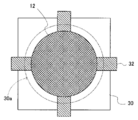
- FIG. 4 is a top view corresponding to the second stage of FIG. 3
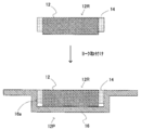
- FIG. 5 is an illustrative view showing a mounting process for attaching the magnet 12R with a ring manufactured in the manufacturing process to the yoke 16 by a change in cross section.
- the numerical values related to the diameter, thickness, etc. given below are examples of optimum design values.
- the magnet 12 in the manufacturing process, is formed into a cylindrical shape having a diameter of 4 mm and a thickness of 1 mm, for example.
- the tolerance of the diameter is usually about 0.1 mm, but may be larger than this.
- the magnet 12 is housed in the mold 30 and a jig is mounted, the center of the magnet 12 and the center of the mold 30 are positioned (mold and jig mounting process), and the mold 30 and the magnet 12 are positioned.
- Molten resin is injected into the gap between the two (resin injection step).
- the mold 30 has a cylindrical recess 30a having a diameter of 4.2 mm and a thickness of 0.8 mm.
- the inner diameter tolerance of the mold 30, that is, the diameter tolerance of the recess 30a can be about 0.05 mm here.
- the magnet 12 is housed in the mold 30 and fixed to the center of the recess 30a so that the upper end of the magnet 12 is sandwiched from four sides by four jigs 32.
- a ring-shaped gap (gap G) having a width of 0.2 mm and a depth of 0.8 mm is provided between the mold 30 and the magnet 12 in a state where the magnet 12 is housed in the mold 30 and fixed by the jig 32. Exists.
- the outer diameter tolerance of the magnet 12R with a ring is about 0.05 mm which is the same as the inner diameter tolerance of the mold 30.
- magnet 12R with a ring is then housed in yoke 16 in the mounting process.
- the yoke 16 is formed by press molding, for example, and has a cylindrical recess 16a having a diameter of 4.2 mm and a thickness of 1 mm.
- the inner diameter tolerance of the yoke 16, that is, the diameter tolerance of the concave portion 16a can be about 0.05 mm.
- the tolerance of the width of the gap G is equal to the above two tolerances, the outer diameter tolerance (0.1 mm) of the magnet 12 and the resin ring 14. Therefore, it is not easy to obtain the same magnetic flux density as that of the speaker 10.
- the magnet 12 is magnetically coupled to the yoke 16.
- a resin ring 14 is inserted in the gap G between the magnet 12 and the yoke 16, and a horizontal coil 22 is disposed above the resin ring 14 (gap G).
- the resin ring 14 has an inner peripheral surface bonded to the side surface of the magnet 12 in an adhesive state, and an outer peripheral surface bonded to the inner peripheral surface of the yoke 16 in a non-adhered state.
- the horizontal coil 22 is mechanically coupled to the diaphragm 20 and is supplied with a current according to an audio signal.
- a magnet 12R with a ring (resin integrated magnet) in which the magnet 12 and the resin ring 14 are bonded together is manufactured (see FIG. 3), and the magnet 12R with the ring is attached to the yoke 16. (See FIG. 4). Therefore, it is not necessary to attach the resin ring 14 to the magnet 12 at the time of assembly, and the magnet 12 is disposed at an appropriate position in the yoke 16 simply by storing the magnet 12R with the ring in the yoke 16. For this reason, it is not necessary to perform the positioning work of the magnet 12, and the work amount at the time of assembly is reduced.
- the magnet 12 can be fixed to the center of the recess 30a if there are at least three jigs 32.
- the resin ring 14 does not have to be a complete ring shape, and may be partially formed on the side surface of the magnet 12 as long as the magnet 12 can be fixed in the yoke 16.
- FIG. 2 is a top view of the embodiment in FIG. 1. It is an illustration figure which shows a part of manufacturing process of FIG. 1 Example by the change of a cross section.
- FIG. 4 is a top view corresponding to the second stage of FIG. 3. It is an illustration figure which shows the other part of the manufacturing process of FIG. 1 Example by the change of a cross section. It is a graph which shows the relationship between the gap width and magnetic flux density in FIG. 1 Example.
Landscapes
- Engineering & Computer Science (AREA)
- Physics & Mathematics (AREA)
- Acoustics & Sound (AREA)
- Signal Processing (AREA)
- Manufacturing & Machinery (AREA)
- Audible-Bandwidth Dynamoelectric Transducers Other Than Pickups (AREA)
Abstract
【構成】スピーカ10はマグネット12および水平コイル22を含む。マグネット12はヨーク16と磁気的に結合し、マグネット12とヨーク16との間の磁気ギャップGには樹脂リング14が介挿される。水平コイル22は、樹脂リング14つまり磁気ギャップGの上方に配置され、樹脂リング14は、その内周面がマグネット12の側面と接着状態で接合し、かつその外周面がヨーク16の内周面と非接着状態で接合する。水平コイル22は、振動板20と機械的に結合し、かつ音声信号に従う電流の供給を受ける。
【効果】水平コイルを用いた高効率で低コストのスピーカが実現可能となる。
Description
この発明は、スピーカに関し、特にたとえば、マグネットおよびこれを収納するヨーク,ならびにマグネット外周およびヨーク内周の間のギャップ上方に配置される板状に巻回したコイル(導線を巻軸に対して直交する面方向に巻いたもの:水平コイル)を備える、スピーカに関する。
この種のスピーカの一例が、特許文献1に開示されている。この背景技術では、ギャップに非磁性材料でできた固定部材が嵌め込まれる。
また、他の一例が特許文献2に開示されている。この背景技術では、ギャップに樹脂が充填される。
特開2006-86942号公報[H04R 9/02, 9/00]
特開2006-94269号公報[H04R 9/00, 7/04, 9/02, 31/00]
この種のスピーカでは、コイル位置において均一で高い磁束密度を得るために、マグネットをヨークの中心に正確に配置すると共に、マグネット外周およびヨーク内周の間に最適幅のギャップを確保することが特に求められる。なぜなら、ギャップ上方に水平コイルを配置すると、ギャップ内に円筒状のコイルを配置したときと比べ、マグネット位置のずれやギャップサイズの精度不足によって磁束分布が不均一となったときの振動板の振動の乱れが大きく、わずかな位置ずれや精度不足でも音質低下が生じるからである。
この種のスピーカに関し、ギャップ幅とギャップ上方に位置された水平コイル位置における磁束密度との関係の一例を図6に示す。図6を参照して、横軸は水平コイルの一方端から他方端への距離(0~1mm)を示し、縦軸は磁束密度を示す。4種類のギャップ幅(ギャップなし,0.1mm,0.2mmおよび0.3mm)にそれぞれ対応する4本の曲線から、ギャップ幅は0.2mmが最適で、この最適値からずれると磁束密度が低下することがわかる。
これから、コイル位置つまりギャップ上方で高い磁束密度を得るには、ギャップ幅の最適値に対する誤差を極力小さくしなければならないことがわかる。この点、特許文献1の技術では、マグネット外周,固定部材内周,固定部材外周およびヨーク内周の4つの面の各々を高い精度で成形する必要がある。しかし、マグネットの外周面は特に、マグネットが焼結体であることから、面精度を高めるのは容易でない。
特許文献1の技術ではまた、組み立てにあたって、作業者はたとえば、マグネットに固定部材を取り付け、そしてこの固定部材付マグネットをヨークに装着するので、作業量が多いという別の問題もある。
一方、特許文献2の技術では、マグネットおよびヨークの各々が樹脂と接着状態で接合するので、面精度を高める必要はないが、組み立てにあたって、治具を用いてマグネットの位置決めを行う必要があるので、ここでも組み立て時の作業量の多さが問題となる。
それゆえに、この発明の主たる目的は、新規な、スピーカならびにマグネット部品およびその製造方法を提供することである。
この発明の他の目的は、ギャップ上方において均一で高い磁束密度が得られる、板状に巻回された水平コイルを用いたスピーカ、ならびに、このようなスピーカに用いられ、組み立て時の作業量を削減できる、マグネット部品およびその製造方法を提供することである。
この発明は、上記の課題を解決するために、以下の構成を採用した。なお、括弧内の参照符号および補足説明等は、この発明の理解を助けるために後述する実施形態との対応関係を示したものであって、この発明を何ら限定するものではない。
第1の発明に従うスピーカは、マグネット、マグネットと磁気的に結合するヨーク、マグネットおよびヨークの間に介挿されて一部がマグネットと接着状態で接合しかつ他の一部がヨークと非接着状態で接合する樹脂部材、樹脂部材の上方に配置されて音声信号に従う電流が供給される板状に巻回された水平コイル、および水平コイルと機械的に結合する振動板を備える。
第1の発明に従うスピーカ(10)では、マグネット(12)とヨーク(16)との間に樹脂部材(14)が介挿される。樹脂部材の上方には振動板(20)と機械的に結合された水平コイル(22)が配置され、この水平コイルに音声信号に従う電流が供給される。
こうしてマグネットによる磁束中のコイルを電流が流れることで、コイルとマグネットとの間に電磁力が作用し、コイルが振動する。コイルは振動板(20)と機械的に結合されており、コイルの振動は振動板へと伝播する。これにより、振動板から音声信号に従う音波が放射される。
ここで、コイル位置における磁束密度は、マグネットとヨークとの間のギャップ(G)つまり樹脂部材のサイズによって変化する。すなわち、樹脂部材のサイズがマグネットおよびヨークに対して最適であるとき、最大の磁束密度が得られる。そして、最適サイズとの誤差(つまりギャップのサイズの公差)が大きいほど、得られる磁束密度は低下する。
この点、樹脂部材は、一部がマグネットと接着状態で接合する一方、他の一部がヨークと非接着状態で接合しているので、前者つまり接着状態で接合している部分の公差は問題とならない。したがって、両方の接合部分が非接着状態の場合と比べ、高い磁束密度を得るのが容易になる。
また、組み立てにあたって、マグネットに樹脂を取り付ける必要がないので、両方の接合部分が非接着状態の場合と比べ、組み立て時の作業量が削減される。両方の接合部分が接着状態の場合と比べても、組み立てにあたって治具で位置決めを行う必要がないので、組み立て時の作業量が削減される。
第1の発明によれば、コイル位置つまりギャップ上方において均一で高い磁束密度が得られる。また、組み立て時の作業量を削減できる。したがって、水平コイルを用いた高効率で低コストのスピーカが実現可能となる。
第2の発明に従うマグネット部品(12P)は、マグネット(12)、マグネットと磁気的に結合するヨーク(16)、およびマグネットおよびヨークの間に介挿されて一部がマグネットと接着状態で接合しかつ他の一部がヨークと非接着状態で接合する樹脂部材(14)を備える。
第2の発明によれば、第1の発明と同様に、組み立て時の作業量が削減される。また、第2の発明をたとえば、水平コイルおよびこの水平コイルと機械的に結合された振動板を有するスピーカに適用することで、水平コイルを用いた高効率で低コストのスピーカが実現可能となる。
第3の発明に従うマグネット部品製造方法は、マグネット(12),マグネットと磁気的に結合するヨーク(16),およびマグネットおよびヨークの間に介挿されて一部がマグネットと接着状態で接合しかつ他の一部がヨークと非接着状態で接合する樹脂部材(14)を有するマグネット部品(12P)を製造する方法であって、マグネットと樹脂部材とが接着状態で接合した樹脂一体型マグネット(12R)を製作する製作工程(図3)、および製作工程で製作された樹脂一体型マグネットをヨークに取り付ける取付工程(図5)を備える。
第3の発明では、樹脂一体型マグネットを製作しておくため、組み立てを行うとき樹脂一体型マグネットをヨークに取り付けるだけでよい。
第3の発明によれば、組み立て時の作業量が削減される。
第4の発明に従うマグネット部品製造方法は、第3の発明に従属し、製作工程では、金型(30)にマグネットを収納して治具で位置決め固定した後さらに溶融樹脂を注入し、注入された溶融樹脂が固化した後に金型および治具を取り外す。
第4の発明では、マグネットは、金型に収納された後、治具で位置決め固定され、金型とマグネットとの間の空隙に溶融樹脂が注入される。金型および治具は、溶融樹脂が固化した後に取り外される。
第4の発明によれば、金型および治具によるインサート成形を行うことで、樹脂一体型マグネットを簡単にかつ精度よく製造できる。
この発明によれば、最適なギャップ幅を精度よく形成することができるので、ギャップ上方において均一で高い磁束密度が得られる。また、組立作業を容易化できる。この結果、水平コイルを用いたスピーカの高効率化および低コスト化が図れる。
この発明の上述の目的,その他の目的,特徴および利点は、図面を参照して行う以下の実施例の詳細な説明から一層明らかとなろう。
図1および図2を参照して、この実施例のスピーカ10は、その側面に樹脂リング14が設けられた円柱形状のマグネット12、およびこの樹脂リング14付きのマグネット12(以下“リング付マグネット12R”)を収納するための凹部が形成された円盤形状のヨーク16を含む。
リング付マグネット12Rでは、マグネット12の側面と樹脂リング14の内周面とが互いに密着している。ただし、図1に示すように、樹脂リング14の厚みはマグネット12の厚みよりも若干小さく、マグネット12の側面のうち下端部分は樹脂リング14で覆われることなく露出している。なお、リング付マグネット12Rは、後述するインサート成形によって実現される。
ヨーク16の内径(凹部の直径)は樹脂リング14の外径と一致しており、リング付マグネット12Rをヨーク16に収納した状態で、樹脂リング14の外周面とヨーク16の内周面との間に隙間は存在しない。
また、ヨーク16の深さ(凹部の厚み)はマグネット12の厚みと一致しており、リング付マグネット12Rをヨーク16に収納した状態で、ヨーク16の上面16uおよびマグネット12の上面12uは同じ高さに位置する。
こうしてヨーク16に収納されたリング付マグネット12R(以下“マグネット部品12P”)は、リング形状を有するフレーム18の背面18bに装着される。フレーム18の前面18fには、円盤形状を有する振動板20が設けられる。
振動板20には、水平コイル22を収納するための扁平円筒形の凹部20aが形成される。凹部20aは、マグネット12からの磁束が最も高密度となる位置、すなわちマグネット12の外周とヨークの内周との間のギャップGの上方に設けられる。水平コイル22は、凹部20aに収納され、振動板20に直接固定される。振動板20は、水平コイル22を凹部20aに収納した状態で、フレーム18によって振動可能に支持される。
水平コイル22へは、たとえば振動板20の裏面に沿って配線された導線(図示せず)を通して音声信号に従う電流が供給される。こうして、マグネット12による磁束中に置かれた水平コイル22に電流を流すことで、マグネット12と水平コイル22との間に電磁力が作用し、これによって水平コイル22が振動する。水平コイル22の振動は振動板20へと伝播し、振動板20から音声信号に従う音波が空気中に放射される。
スピーカ10の主要部品であるマグネット部品12Pは、たとえば図3,図4および図5の要領で製造される。図3は、金型30および治具32を利用したインサート成形によるリング付マグネット12Rの製作工程を断面の変化によって示す図解図である。図4は図3の第2段に対応する上面図であり、図5は、製作工程で製作されたリング付マグネット12Rをヨーク16に取り付ける取付工程を断面の変化によって示す図解図である。なお、以下で挙げる直径,厚さなどに関する数値は、設計上の最適値の一例である。
図3および図4を参照して、製作工程では、マグネット12は、たとえば直径4mm,厚さ1mmの円柱形状に成形される。直径の公差は、通常0.1mm程度であるが、これより大きくても構わない。
次に、このマグネット12を金型30に収納して治具を装着して、マグネット12の中心と金型30の中心を位置決めし(金型&治具装着工程)、金型30とマグネット12との間の隙間に溶融樹脂を注入する(樹脂注入工程)。詳しくは、金型30は、直径4.2mm,厚さ0.8mmの円柱形状の凹部30aを有する。なお、金型30の内径公差、つまり凹部30aの直径公差は、ここでは0.05mm程度とすることが可能である。
マグネット12は、金型30内に収納され、その上端部を4つの治具32で四方から挟むようにして、凹部30aの中央に固定される。マグネット12を金型30に収納し治具32で固定した状態で、金型30とマグネット12との間には、幅0.2mm,深さ0.8mmのリング形状の隙間(ギャップG)が存在する。この隙間に液状の樹脂を注入し、注入された樹脂を固化させることで、マグネット12の側面に密着状態で接合した樹脂リング14が形成される。
そして、樹脂が固化した後に金型30を取り外せば(金型&治具取り外し工程)、リング付マグネット12Rが得られる。リング付マグネット12Rの外径公差は、金型30の内径公差と同じ0.05mm程度となる。
図4を参照して、リング付マグネット12Rはその後、取付工程においてヨーク16に収納される。ヨーク16は、たとえばプレス成形によるもので、直径4.2mm,厚さ1mmの円柱形状の凹部16aを有する。ヨーク16の内径公差、つまり凹部16aの直径公差は、0.05mm程度とすることが可能である。これにより、マグネット部品12Pが得られる。
こうして製造されたマグネット部品12Pでは、樹脂リング14つまりギャップGの幅の公差は、リング付マグネット12Rの外径公差およびヨーク16の内径公差の合計(0.05mm+0.05mm=0.1mm)となる。したがって、ギャップGの幅を最適幅(=0.2mm)に近づけることが容易となり、ギャップ上方において均一で高い磁束密度が得られる。
なお、樹脂リング14を別途成形して、これをマグネット12に装着したと仮定すると、ギャップGの幅の公差は、上記の2公差にマグネット12の外径公差(0.1mm)および樹脂リング14の内径公差(0.05mm)を加えた4公差(=0.25mm)となり、スピーカ10と同様の磁束密度を得るのは容易でない。
以上から明らかなように、この実施例のスピーカ10では、マグネット12はヨーク16と磁気的に結合する。マグネット12とヨーク16との間のギャップGには樹脂リング14が介挿され、樹脂リング14(ギャップG)の上方には水平コイル22が配置される。樹脂リング14は、その内周面がマグネット12の側面と接着状態で接合し、かつその外周面がヨーク16の内周面と非接着状態で接合する。水平コイル22は、振動板20と機械的に結合し、音声信号に従う電流の供給を受ける。
こうしてマグネット12による磁束中に配置された水平コイル22を電流が流れることで、水平コイル22とマグネット12との間に電磁力が作用し、水平コイル22が上下に振動する。水平コイル22は振動板20と機械的に結合されており、水平コイル22の振動は振動板20へと伝播する。これにより、振動板20から音声信号に従う音波が放射される。
このように、樹脂リング14の内周面とマグネット12の側面とが接着状態で接合し、かつ樹脂リング14の外周面とヨーク16の内周面とが非接着状態で接合しているので、両方の接合部分が非接着状態の場合と比べ、ギャップ幅の公差が小さく、ギャップ上方において均一で高い磁束密度が得られる。
スピーカ10を製造するにあたっては、マグネット12と樹脂リング14とが接着状態で接合したリング付マグネット12R(樹脂一体型マグネット)を製作し(図3参照)、このリング付マグネット12Rをヨーク16に取り付ける(図4参照)。したがって、組み立ての際、マグネット12に樹脂リング14を取り付ける必要がなく、リング付マグネット12Rをヨーク16に単に収納するだけで、マグネット12がヨーク16内の適切な位置に配置される。このため、マグネット12の位置決め作業を行う必要もなく、組み立て時の作業量が削減される。
なお、この実施例ではインサート成形にあたって4個の治具32を用いたが(図4参照)、少なくとも3個の治具32があれば、マグネット12を凹部30aの中央に固定できるのはいうまでもない。また、樹脂リング14は完全なリング状である必要はなく、ヨーク16内にマグネット12が固定できれば、マグネット12の側面に部分的に形成されていてもよい。
10 …スピーカ
12 …マグネット
12R …リング付マグネット(樹脂一体型マグネット)
12P …マグネット部品
14 …樹脂リング
16 …ヨーク
18 …フレーム
20 …振動板
22 …水平コイル
24a~24c …支持部材
30 …金型
32 …治具
12 …マグネット
12R …リング付マグネット(樹脂一体型マグネット)
12P …マグネット部品
14 …樹脂リング
16 …ヨーク
18 …フレーム
20 …振動板
22 …水平コイル
24a~24c …支持部材
30 …金型
32 …治具
Claims (4)
- マグネット、
前記マグネットと磁気的に結合するヨーク、
前記マグネットおよび前記ヨークの間に介挿されて一部が前記マグネットと接着状態で接合しかつ他の一部が前記ヨークと非接着状態で接合する樹脂部材、
前記樹脂部材の上方に配置されて音声信号に従う電流が供給される板状に巻回したコイル、および
前記コイルと機械的に結合する振動板を備える、スピーカ。 - マグネット、
前記マグネットと磁気的に結合するヨーク、および
前記マグネットおよび前記ヨークの間に介挿されて一部が前記マグネットと接着状態で接合しかつ他の一部が前記ヨークと非接着状態で接合する樹脂部材を備える、マグネット部品。 - マグネット,前記マグネットと磁気的に結合するヨーク,および前記マグネットおよび前記ヨークの間に介挿されて一部が前記マグネットと接着状態で接合しかつ他の一部が前記ヨークと非接着状態で接合する樹脂部材を有するマグネット部品を製造する方法であって、
前記マグネットと前記樹脂部材とが接着状態で接合した樹脂一体型マグネットを製作する製作工程、および
前記製作工程で製作された樹脂一体型マグネットを前記ヨークに取り付ける取付工程を備える、マグネット部品製造方法。 - 前記製作工程では、金型に前記マグネットを収納して治具で固定した後さらに溶融樹脂を注入し、注入された溶融樹脂が固化した後に前記金型および前記治具を取り外す、請求項3記載のマグネット部品製造方法。
Applications Claiming Priority (2)
| Application Number | Priority Date | Filing Date | Title |
|---|---|---|---|
| JP2008025850A JP5132344B2 (ja) | 2008-02-06 | 2008-02-06 | スピーカならびにマグネット部品およびその製造方法 |
| JP2008-025850 | 2008-02-06 |
Publications (1)
| Publication Number | Publication Date |
|---|---|
| WO2009098926A1 true WO2009098926A1 (ja) | 2009-08-13 |
Family
ID=40952004
Family Applications (1)
| Application Number | Title | Priority Date | Filing Date |
|---|---|---|---|
| PCT/JP2009/050553 Ceased WO2009098926A1 (ja) | 2008-02-06 | 2009-01-16 | スピーカならびにマグネット部品およびその製造方法 |
Country Status (2)
| Country | Link |
|---|---|
| JP (1) | JP5132344B2 (ja) |
| WO (1) | WO2009098926A1 (ja) |
Citations (3)
| Publication number | Priority date | Publication date | Assignee | Title |
|---|---|---|---|---|
| JPS6280494U (ja) * | 1985-11-09 | 1987-05-22 | ||
| WO2005117489A1 (ja) * | 2004-05-27 | 2005-12-08 | Matsushita Electric Industrial Co., Ltd. | スピーカ |
| JP2006042110A (ja) * | 2004-07-29 | 2006-02-09 | Matsushita Electric Ind Co Ltd | 音響発生装置およびこの音響発生装置を搭載した電子機器、装置 |
-
2008
- 2008-02-06 JP JP2008025850A patent/JP5132344B2/ja not_active Expired - Fee Related
-
2009
- 2009-01-16 WO PCT/JP2009/050553 patent/WO2009098926A1/ja not_active Ceased
Patent Citations (3)
| Publication number | Priority date | Publication date | Assignee | Title |
|---|---|---|---|---|
| JPS6280494U (ja) * | 1985-11-09 | 1987-05-22 | ||
| WO2005117489A1 (ja) * | 2004-05-27 | 2005-12-08 | Matsushita Electric Industrial Co., Ltd. | スピーカ |
| JP2006042110A (ja) * | 2004-07-29 | 2006-02-09 | Matsushita Electric Ind Co Ltd | 音響発生装置およびこの音響発生装置を搭載した電子機器、装置 |
Also Published As
| Publication number | Publication date |
|---|---|
| JP2009188691A (ja) | 2009-08-20 |
| JP5132344B2 (ja) | 2013-01-30 |
Similar Documents
| Publication | Publication Date | Title |
|---|---|---|
| KR101697251B1 (ko) | 스피커 및 스피커 조립방법 | |
| US7848536B2 (en) | Voice coil assembly, loudspeaker using the same, and method for producing the same | |
| JP4219225B2 (ja) | スピーカ装置 | |
| JP4764162B2 (ja) | スピーカ装置 | |
| CN1149175A (zh) | 物镜促动器及其制造方法 | |
| CN1302171A (zh) | 电声换能器及其制造方法 | |
| JP4597230B2 (ja) | スピーカ装置、電気機器、およびその製造方法 | |
| JP5132344B2 (ja) | スピーカならびにマグネット部品およびその製造方法 | |
| JP2001128289A (ja) | スピーカ | |
| CN107801143B (zh) | 电动换能器和制造其的方法及膜系统模块和磁体系统模块 | |
| JP2009049762A (ja) | スピーカ用磁気回路、およびスピーカ装置 | |
| JP2010034620A (ja) | ボイスコイル組立体およびこれを用いたスピーカー、並びにその製造方法 | |
| JP2007329639A (ja) | スピーカ装置の製造方法、およびスピーカ装置 | |
| JP2006050410A (ja) | 電気音響変換装置およびその製造方法 | |
| JP4893798B2 (ja) | スピーカ | |
| JP4690942B2 (ja) | スピーカ装置の製造方法およびスピーカ装置の組立治具 | |
| JP2018117203A (ja) | 骨伝導振動子およびその製造方法 | |
| JP2012151707A (ja) | ダイナミックマイクロホンユニットの製造方法 | |
| JP2007336145A (ja) | スピーカー装置用磁気回路の製造方法 | |
| JP2006020103A (ja) | スピーカ用のケース、スピーカ並びにスピーカ用のケースの製造方法 | |
| JP4777866B2 (ja) | スピーカ | |
| JP7414254B2 (ja) | 電気音響変換器と電気音響変換器の製造方法 | |
| JP3125440B2 (ja) | スピーカの製造方法 | |
| JP2003078992A (ja) | スピーカの磁気回路構造及びスピーカ | |
| JP2006340210A (ja) | 電気音響変換器 |
Legal Events
| Date | Code | Title | Description |
|---|---|---|---|
| 121 | Ep: the epo has been informed by wipo that ep was designated in this application |
Ref document number: 09708398 Country of ref document: EP Kind code of ref document: A1 |
|
| NENP | Non-entry into the national phase |
Ref country code: DE |
|
| 122 | Ep: pct application non-entry in european phase |
Ref document number: 09708398 Country of ref document: EP Kind code of ref document: A1 |