WO2009098787A1 - 体液採取用回路基板 - Google Patents
体液採取用回路基板 Download PDFInfo
- Publication number
- WO2009098787A1 WO2009098787A1 PCT/JP2008/055147 JP2008055147W WO2009098787A1 WO 2009098787 A1 WO2009098787 A1 WO 2009098787A1 JP 2008055147 W JP2008055147 W JP 2008055147W WO 2009098787 A1 WO2009098787 A1 WO 2009098787A1
- Authority
- WO
- WIPO (PCT)
- Prior art keywords
- circuit board
- puncture needle
- guard
- puncture
- blood
- Prior art date
Links
Images


Classifications
-
- A—HUMAN NECESSITIES
- A61—MEDICAL OR VETERINARY SCIENCE; HYGIENE
- A61B—DIAGNOSIS; SURGERY; IDENTIFICATION
- A61B5/00—Measuring for diagnostic purposes; Identification of persons
- A61B5/15—Devices for taking samples of blood
- A61B5/150007—Details
- A61B5/150374—Details of piercing elements or protective means for preventing accidental injuries by such piercing elements
- A61B5/150534—Design of protective means for piercing elements for preventing accidental needle sticks, e.g. shields, caps, protectors, axially extensible sleeves, pivotable protective sleeves
- A61B5/150541—Breakable protectors, e.g. caps, shields or sleeves, i.e. protectors separated destructively, e.g. by breaking a connecting area
- A61B5/150557—Protectors removed by bending
-
- A—HUMAN NECESSITIES
- A61—MEDICAL OR VETERINARY SCIENCE; HYGIENE
- A61B—DIAGNOSIS; SURGERY; IDENTIFICATION
- A61B5/00—Measuring for diagnostic purposes; Identification of persons
- A61B5/145—Measuring characteristics of blood in vivo, e.g. gas concentration, pH value; Measuring characteristics of body fluids or tissues, e.g. interstitial fluid, cerebral tissue
- A61B5/14532—Measuring characteristics of blood in vivo, e.g. gas concentration, pH value; Measuring characteristics of body fluids or tissues, e.g. interstitial fluid, cerebral tissue for measuring glucose, e.g. by tissue impedance measurement
-
- A—HUMAN NECESSITIES
- A61—MEDICAL OR VETERINARY SCIENCE; HYGIENE
- A61B—DIAGNOSIS; SURGERY; IDENTIFICATION
- A61B5/00—Measuring for diagnostic purposes; Identification of persons
- A61B5/145—Measuring characteristics of blood in vivo, e.g. gas concentration, pH value; Measuring characteristics of body fluids or tissues, e.g. interstitial fluid, cerebral tissue
- A61B5/1486—Measuring characteristics of blood in vivo, e.g. gas concentration, pH value; Measuring characteristics of body fluids or tissues, e.g. interstitial fluid, cerebral tissue using enzyme electrodes, e.g. with immobilised oxidase
-
- A—HUMAN NECESSITIES
- A61—MEDICAL OR VETERINARY SCIENCE; HYGIENE
- A61B—DIAGNOSIS; SURGERY; IDENTIFICATION
- A61B5/00—Measuring for diagnostic purposes; Identification of persons
- A61B5/15—Devices for taking samples of blood
- A61B5/150007—Details
- A61B5/150015—Source of blood
- A61B5/150022—Source of blood for capillary blood or interstitial fluid
-
- A—HUMAN NECESSITIES
- A61—MEDICAL OR VETERINARY SCIENCE; HYGIENE
- A61B—DIAGNOSIS; SURGERY; IDENTIFICATION
- A61B5/00—Measuring for diagnostic purposes; Identification of persons
- A61B5/15—Devices for taking samples of blood
- A61B5/150007—Details
- A61B5/150206—Construction or design features not otherwise provided for; manufacturing or production; packages; sterilisation of piercing element, piercing device or sampling device
- A61B5/150274—Manufacture or production processes or steps for blood sampling devices
- A61B5/150282—Manufacture or production processes or steps for blood sampling devices for piercing elements, e.g. blade, lancet, canula, needle
-
- A—HUMAN NECESSITIES
- A61—MEDICAL OR VETERINARY SCIENCE; HYGIENE
- A61B—DIAGNOSIS; SURGERY; IDENTIFICATION
- A61B5/00—Measuring for diagnostic purposes; Identification of persons
- A61B5/15—Devices for taking samples of blood
- A61B5/150007—Details
- A61B5/150358—Strips for collecting blood, e.g. absorbent
-
- A—HUMAN NECESSITIES
- A61—MEDICAL OR VETERINARY SCIENCE; HYGIENE
- A61B—DIAGNOSIS; SURGERY; IDENTIFICATION
- A61B5/00—Measuring for diagnostic purposes; Identification of persons
- A61B5/15—Devices for taking samples of blood
- A61B5/150007—Details
- A61B5/150374—Details of piercing elements or protective means for preventing accidental injuries by such piercing elements
- A61B5/150381—Design of piercing elements
- A61B5/150412—Pointed piercing elements, e.g. needles, lancets for piercing the skin
- A61B5/150435—Specific design of proximal end
-
- A—HUMAN NECESSITIES
- A61—MEDICAL OR VETERINARY SCIENCE; HYGIENE
- A61B—DIAGNOSIS; SURGERY; IDENTIFICATION
- A61B5/00—Measuring for diagnostic purposes; Identification of persons
- A61B5/15—Devices for taking samples of blood
- A61B5/150007—Details
- A61B5/150374—Details of piercing elements or protective means for preventing accidental injuries by such piercing elements
- A61B5/150381—Design of piercing elements
- A61B5/150503—Single-ended needles
-
- A—HUMAN NECESSITIES
- A61—MEDICAL OR VETERINARY SCIENCE; HYGIENE
- A61B—DIAGNOSIS; SURGERY; IDENTIFICATION
- A61B5/00—Measuring for diagnostic purposes; Identification of persons
- A61B5/15—Devices for taking samples of blood
- A61B5/150007—Details
- A61B5/150374—Details of piercing elements or protective means for preventing accidental injuries by such piercing elements
- A61B5/150534—Design of protective means for piercing elements for preventing accidental needle sticks, e.g. shields, caps, protectors, axially extensible sleeves, pivotable protective sleeves
- A61B5/15058—Joining techniques used for protective means
- A61B5/150618—Integrally moulded protectors, e.g. protectors simultaneously moulded together with a further component, e.g. a hub, of the piercing element
-
- A—HUMAN NECESSITIES
- A61—MEDICAL OR VETERINARY SCIENCE; HYGIENE
- A61B—DIAGNOSIS; SURGERY; IDENTIFICATION
- A61B5/00—Measuring for diagnostic purposes; Identification of persons
- A61B5/15—Devices for taking samples of blood
- A61B5/150007—Details
- A61B5/150374—Details of piercing elements or protective means for preventing accidental injuries by such piercing elements
- A61B5/150534—Design of protective means for piercing elements for preventing accidental needle sticks, e.g. shields, caps, protectors, axially extensible sleeves, pivotable protective sleeves
- A61B5/150694—Procedure for removing protection means at the time of piercing
- A61B5/150717—Procedure for removing protection means at the time of piercing manually removed
-
- A—HUMAN NECESSITIES
- A61—MEDICAL OR VETERINARY SCIENCE; HYGIENE
- A61B—DIAGNOSIS; SURGERY; IDENTIFICATION
- A61B5/00—Measuring for diagnostic purposes; Identification of persons
- A61B5/15—Devices for taking samples of blood
- A61B5/151—Devices specially adapted for taking samples of capillary blood, e.g. by lancets, needles or blades
- A61B5/15101—Details
- A61B5/15103—Piercing procedure
- A61B5/15105—Purely manual piercing, i.e. the user pierces the skin without the assistance of any driving means or driving devices
-
- A—HUMAN NECESSITIES
- A61—MEDICAL OR VETERINARY SCIENCE; HYGIENE
- A61B—DIAGNOSIS; SURGERY; IDENTIFICATION
- A61B5/00—Measuring for diagnostic purposes; Identification of persons
- A61B5/15—Devices for taking samples of blood
- A61B5/151—Devices specially adapted for taking samples of capillary blood, e.g. by lancets, needles or blades
- A61B5/15142—Devices intended for single use, i.e. disposable
-
- A—HUMAN NECESSITIES
- A61—MEDICAL OR VETERINARY SCIENCE; HYGIENE
- A61B—DIAGNOSIS; SURGERY; IDENTIFICATION
- A61B5/00—Measuring for diagnostic purposes; Identification of persons
- A61B5/15—Devices for taking samples of blood
- A61B5/157—Devices characterised by integrated means for measuring characteristics of blood
-
- A—HUMAN NECESSITIES
- A61—MEDICAL OR VETERINARY SCIENCE; HYGIENE
- A61B—DIAGNOSIS; SURGERY; IDENTIFICATION
- A61B2562/00—Details of sensors; Constructional details of sensor housings or probes; Accessories for sensors
- A61B2562/02—Details of sensors specially adapted for in-vivo measurements
- A61B2562/0295—Strip shaped analyte sensors for apparatus classified in A61B5/145 or A61B5/157
Definitions
- the present invention relates to a circuit board for collecting body fluid, and more particularly, to a circuit board for collecting body fluid used for measuring a component of body fluid by connecting to a device for measuring the component of body fluid.
- Diabetes is insulin-dependent (type I) and non-insulin-dependent (type II), and the former requires regular administration of insulin. Therefore, in the former, a treatment method is adopted in which a patient collects blood himself, measures blood glucose level himself, and administers insulin by himself at a dose corresponding to the blood glucose level.
- blood glucose level measuring devices are known in which the patient himself can collect blood individually and measure the blood glucose level.
- a fluid collection device includes a reaction zone in which an electrode is inserted and provided in the center of the main body, a puncture needle that protrudes outward from the center of the main body, and a capillary passage that communicates the electrode and the puncture needle (for example, see the following Patent Document 1.) JP 2004-493 A
- the puncture needle and the reaction zone are formed integrally with the main body, the measurement preparation is simple.
- an electrode that is a separate member from the reaction zone is inserted into the reaction zone to measure blood components.
- the blood detection accuracy becomes unstable, and there is a problem in that it cannot be measured accurately.
- the puncture needle protrudes outward from the center of the main body and is exposed. Therefore, before the puncture, the puncture needle comes into contact with other members and is easily damaged, and in such a case, it is difficult to bleed with the puncture needle at the time of puncture.
- An object of the present invention is to provide a circuit board for collecting body fluid, which can accurately measure the components of body fluid with a simple configuration and can prevent the puncture needle from being damaged.
- a body fluid collection circuit board of the present invention comprises an insulating layer, an electrode supported by the insulating layer, a terminal for connecting to a device for measuring a component of body fluid, and the electrode.
- a puncture needle for guarding the distal end of the puncture needle, and facing the puncture needle on the downstream side in the puncture direction of the puncture needle.
- This body fluid collecting circuit board includes a circuit board portion and a puncture needle formed integrally therewith. Therefore, body fluid can be flowed out by puncturing with the puncture needle, and the flowed body fluid can be easily brought into contact with the electrode of the circuit board.
- electrodes, terminals, and wirings are integrally provided as a conductor pattern in the circuit board portion. Therefore, the detection accuracy of the component of the body fluid that contacts the electrode can be improved, and the measurement accuracy can be improved.
- the components of the body fluid can be accurately measured with a simple configuration, and the operation can be simplified.
- the tip of the puncture needle can be guarded by the guard portion, so that the puncture needle can be prevented from being damaged. Therefore, damage to the puncture needle can be reliably prevented before puncturing, so that at the time of puncturing, the body fluid can be surely discharged by the tip of the puncture needle, and the component of the body fluid that has flowed out can be detected.
- the body fluid collection circuit board of the present invention further includes a release portion for releasing the guard by the guard portion by separating the guard portion and the puncture needle.
- the release part allows the guard part and the puncture needle to be separated, and the guard by the guard part can be released. Therefore, before the puncture, the guard part can be easily released during puncture while preventing damage to the puncture needle.
- the puncture needle can be reliably exposed.
- the guard part is supported by the circuit board part, and the release part is provided so as to be bent on the upstream side of the puncture needle with respect to the tip of the puncture needle in the guard part.
- the release portion By bending the release portion upstream of the puncture needle with respect to the tip of the puncture needle in the guard portion, the guard portion and the puncture needle can be reliably separated, and the guard by the guard portion can be reliably released. Further, it is preferable that the release portion is provided so as to be bendable on the upstream side in the puncture direction with respect to the tip of the puncture needle in the puncture needle or the circuit board portion.
- the guard part and the puncture needle can be reliably separated, and the guard by the guard part is reliably released. Can do.
- circuit board for collecting body fluid it is possible to accurately measure the components of body fluid with a simple configuration, and to simplify the operation.
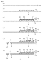
- FIG. 1 shows a circuit board for blood collection as an embodiment of a circuit board for body fluid collection according to the present invention, in which (a) is a plan view and (b) is a longitudinal view taken along line AA in (a). A direction sectional view is shown.
- 2A and 2B are manufacturing process diagrams showing an example of a method for manufacturing the circuit board for blood collection shown in FIG. 1, wherein FIG. 2A is a process for preparing a metal substrate, and FIG. 2B is a process for forming a base insulating layer.
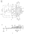
- FIG. 3 is an explanatory view showing an example of a method of using the circuit board for blood collection shown in FIG. 1, wherein (a) is a state in which the guard by the guard part is released, and (b) is a state in which the puncture needle is punctured. (C) shows a state in which an electrode is brought into contact with the puncture site, and (d) shows a state in which a circuit board for blood collection is inserted into the blood sugar level measuring device.
- FIG. 4 is an explanatory view showing an example of a method for using a blood collection circuit board (an embodiment in which a guard-side groove is formed in a bent portion), which is another embodiment of the body fluid collection circuit board of the present invention.
- FIG. 5 is an explanatory view showing an example of a method for using a blood collection circuit board (an embodiment in which a guard-side through hole is formed in a bent portion), which is another embodiment of the body fluid collection circuit board of the present invention.
- FIG. 6 is a circuit board for blood collection which is another embodiment of the circuit board for body fluid collection of the present invention (a mode in which the bent part is provided in the circuit board part), where (a) is a plan view, and (b) ) Shows a longitudinal sectional view along the line BB in FIG.
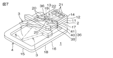
- FIG. 7 is an explanatory view showing an example of a method for using the circuit board for blood collection shown in FIG. 6 (an embodiment in which a circuit-side recess is formed in the bent portion).
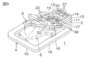
- FIG. 8 is an explanatory view showing an example of a method of using a blood collection circuit board (an embodiment in which a circuit-side groove is formed in a bent portion), which is another embodiment of the body fluid collection circuit board of the present invention.
- FIG. 9 is an explanatory view showing an example of a method of using a blood collection circuit board (an embodiment in which a circuit side through hole is formed in a bent portion), which is another embodiment of the body fluid collection circuit board of the present invention.
- FIG. 10 is an explanatory view showing an example of a method for using a blood collection circuit board (an embodiment in which the circuit board part also serves as a guard part), which is another embodiment of the circuit board for body fluid collection of the present invention.
- FIG. 1 shows a circuit board for blood collection as an embodiment of a circuit board for body fluid collection according to the present invention, in which (a) is a plan view and (b) is a longitudinal view taken along line AA in (a). A direction sectional view is shown.
- this blood collection circuit board 1 collects blood by puncturing a skin such as a finger by a patient and measures the amount of glucose in the collected blood (see FIG. 3 (d)). ).
- the circuit board 1 for blood collection is prepared as a disposable type that is discarded after each measurement.
- the blood collection circuit board 1 includes a circuit board part 2, a puncture needle 3, and a guard part 4.
- the circuit board portion 2 is arranged in the longitudinal direction of the blood collection circuit board 1 (left and right direction in FIG. 1A), that is, upstream in the puncture direction of the puncture needle 3 described later (right side in FIG. 1A). ing.
- the circuit board 2 is formed in a substantially rectangular shape (rectangular shape) in plan view that is long in the puncturing direction.
- the circuit board portion 2 is laminated on the surface of the metal substrate 11, the base insulating layer 12 as an insulating layer laminated on the surface of the metal substrate 11, and the surface of the base insulating layer 12.
- the conductive pattern 13 and the insulating cover layer 14 provided on the surface of the insulating base layer 12 so as to cover the conductive pattern 13 are provided.
- the metal substrate 11 is formed in the circuit board portion 2 in a substantially rectangular shape in plan view extending in the longitudinal direction from a metal foil or the like.
- the metal that forms the metal substrate 11 for example, nickel, chromium, iron, stainless steel (SUS304, SUS430, SUS316L) or the like is used.
- stainless steel is used.
- the thickness of the metal substrate 11 is, for example, 10 to 300 ⁇ m, preferably 20 to 100 ⁇ m.
- the thickness is less than 10 ⁇ m, there are cases where the skin cannot be punctured (described later) due to insufficient strength, or the guard portion 4 cannot reliably guard (described later).
- the thickness exceeds 300 ⁇ m, pain may be felt at the time of puncturing, and the skin may be excessively damaged, or the bent portion 19 (described later) may not be bent smoothly.
- the base insulating layer 12 is formed in the circuit board portion 2 in the same shape as the metal substrate 11 in plan view.
- a synthetic resin such as a polyimide resin, a polycarbonate resin, a polyethylene resin, a polyethylene terephthalate resin, an epoxy resin, or a fluororesin is used. From the viewpoint of mechanical durability and chemical resistance, a polyimide resin is preferably used.
- the insulating base layer 12 has a thickness of, for example, 3 to 50 ⁇ m, preferably 5 to 25 ⁇ m. If the thickness is less than 3 ⁇ m, insulation defects such as pinholes may occur. On the other hand, when the thickness exceeds 50 ⁇ m, it may be difficult to perform cutting or outer shape processing.
- the conductor pattern 13 is supported by the base insulating layer 12 in the circuit board unit 2, and includes three electrodes 20, three terminals 21, and three wirings 22.
- the three electrodes 20 are arranged on the downstream side in the puncture direction in the circuit board unit 2. These electrodes 20 are formed in a substantially rectangular shape in plan view, two of which are arranged in parallel in the width direction (direction orthogonal to the longitudinal direction), and the other one is downstream in the puncture direction from the above two Is arranged.
- the three electrodes 20 correspond to any one of a working electrode, a counter electrode, and a reference electrode.
- the length of one side of each electrode 20 is, for example, 100 ⁇ m to 2.5 mm.
- the three electrodes 20 are arranged, for example, within 0.2 to 5 mm, preferably within 0.5 to 3 mm from the tip 5 of the puncture needle 3 in the puncture direction. If the distance between the tip 5 of the puncture needle 3 and the electrode 20 is too short, the electrode 20 pierces the skin together with the puncture needle 3, and a drug 30 (described later) applied to the surface of the electrode 20 diffuses into the body and is accurate. May interfere with measurement. On the other hand, if the distance between the tip 5 of the puncture needle 3 and the electrode 20 is too long, a structure for utilizing suction or capillary action is required to introduce blood from the puncture needle 3 to the electrode 20.
- the three terminals 21 are provided corresponding to the three electrodes 20, and are arranged on the upstream side in the puncture direction of the circuit board unit 2 in order to connect to the blood glucose level measuring device 31. These terminals 21 are formed in a substantially rectangular shape in plan view that is slightly smaller than the electrode 20. The three terminals 21 are arranged in parallel in the width direction. The three wirings 22 are arranged in parallel at intervals in the width direction, and are provided along the longitudinal direction so as to electrically connect each electrode 20 and each corresponding terminal 21. . Each electrode 20, each terminal 21, and the wiring 22 connected to them are continuously and integrally provided. The length in the width direction of each wiring 22 is, for example, 0.01 to 2 mm, and the length in the longitudinal direction of each wiring 22 is, for example, 5 to 28 mm.
- the conductive material for forming the conductive pattern 13 for example, a metal such as iron, nickel, chromium, copper, gold, silver, platinum, or an alloy thereof is used.
- the conductor material is appropriately selected from the viewpoint of adhesion to the insulating base layer 12 and the insulating cover layer 14 and ease of processing. Also, two or more kinds of conductor materials can be laminated.
- the thickness of the conductor pattern 13 is, for example, 5 to 50 ⁇ m, preferably 10 to 20 ⁇ m.
- the insulating cover layer 14 is provided on the surface of the insulating base layer 12 exposed from the conductor pattern 13 so as to cover each wiring 22 in the circuit board portion 2. Specifically, the downstream end edge in the puncture direction of the insulating cover layer 14 is formed in a straight line along the width direction on the upstream side in the puncture direction so that the three electrodes 20 are exposed. The insulating cover layer 14 is formed with openings 29 for exposing the terminals 21. As an insulating material for forming the insulating cover layer 14, an insulating material similar to that of the above-described insulating base layer 12 is used. The insulating cover layer 14 has a thickness of 2 to 50 ⁇ m, for example.
- the circuit board portion 2 is provided with a stopper portion 8.
- the stopper portion 8 is provided at the downstream end portion in the puncture direction of the circuit board 2 so as to protrude along the both outer sides in the width direction from the outer ends in the width direction.
- the protruding length of the stopper portion 8 to both outer sides in the width direction is, for example, 0.1 to 2 mm.
- Each stopper portion 8 is formed in a substantially rectangular shape in plan view, and its downstream end edge in the puncture direction is formed on the same straight line as the downstream end edge of the base insulating layer 12 along the width direction. .
- the downstream end edge of the stopper portion 8 in the puncture direction is, for example, arranged so as to be spaced from the tip 5 of the puncture needle 3 to the upstream side in the puncture direction of the puncture needle 3 by 0.3 to 2.0 mm.
- the stopper portion 8 is formed of a metal substrate 11 and a base insulating layer 12.
- the metal substrate 11 and the base insulating layer 12 are formed in the stopper portion 8 in the same shape in plan view.
- the puncture needle 3 is provided for collecting blood by puncture. That is, the puncture needle 3 is disposed adjacent to the downstream side of the circuit board portion 2 in the puncture direction, and is formed integrally with the circuit board portion 2. Specifically, the puncture needle 3 protrudes from the circuit board portion 2 toward the downstream side in the puncture direction. Further, the puncture needle 3 is formed in a substantially triangular shape (isosceles triangle shape) in plan view in which the tip 5 (end portion on the downstream side in the puncture direction) is sharpened along the longitudinal direction.
- the puncture needle 3 is formed from a metal substrate 11.
- the angle ⁇ of the tip 5 of the puncture needle 3 is, for example, 10 to 30 °, and preferably 15 to 25 °. If the angle ⁇ of the tip 5 is less than 10 °, the skin may not be punctured due to insufficient strength. On the other hand, if the angle ⁇ exceeds 30 °, it may be difficult to puncture.
- the length of the puncture needle 3 in the longitudinal direction is, for example, 0.3 to 2 mm.
- the guard part 4 is provided to guard the tip 5 of the puncture needle 3. That is, the guard part 4 is formed in a substantially rectangular frame shape surrounding the puncture needle 3 in plan view. Further, the guard part 4 is integrally provided with a support part 16 and a main body part 15.
- the support part 16 is supported by the circuit board part 2 and is formed in a substantially L shape in plan view that is continuous with the circuit board part 2. Further, the support portion 16 includes a base portion 17 projecting outward in the width direction from the middle of the circuit board portion 2 in the puncture direction (between the upstream side and the downstream side in the puncture direction), and both width direction outer end portions of the base portion 17. A side portion 18 extending toward the downstream side in the puncture direction is integrally provided. Further, the downstream end portion of the side portion 18 in the puncture direction is disposed downstream of the distal end 5 of the puncture needle 3 in the puncture direction.
- the main body 15 is supported by the support 16. That is, the main body portion 15 is constructed between the end portions on the downstream side in the puncture direction of the two side portions 18 and is formed in a substantially rectangular shape in plan view extending along the width direction. Thereby, the main-body part 15 is opposingly arranged by the front-end
- the length L1 of the main body 15 (the width in the width direction and the distance in the width direction between the two side portions 18) L1 is, for example, 1 to 20 mm, preferably 3 to 10 mm.
- the length of the base portion 17 (the width in the width direction, that is, the distance in the width direction between the outer edge in the width direction of the circuit board portion 2 and the outer edge in the width direction of the side portion 18) L2 is, for example, 0. It is 3 to 10 mm, preferably 1 to 5 mm.
- the length L3 of the side portion 18 (the length in the puncture direction between the downstream edge in the puncture direction of the base portion 17 and the downstream edge in the puncture direction of the main body portion 15) L3 is, for example, It is 1 to 20 mm, preferably 3 to 10 mm.
- the distance L4 in the puncture direction between the main body 15 and the puncture needle 3 is, for example, 0.05 to 3 mm, preferably 0.1 to 2 mm.
- the distance L5 in the width direction between the side portion 18 and the stopper portion 8 is, for example, 0.1 to 3 mm, preferably 0.5 to 2 mm.
- the width (length in the puncture direction of the base portion 17 and the length in the width direction of the side portion 18) W1 of the support portion 16 in the guard portion 4 and the width (length in the puncture direction) W2 of the main body portion 15 are the same. Alternatively, they may be different, for example, 0.5 to 5 mm, preferably 1 to 3 mm.
- the guard portion 4 is formed from a metal substrate 11. Furthermore, the guard part 4 is provided with a bent part 19 as a release part.
- the bent portion 19 releases the guard against the distal end 5 of the puncture needle 3 by the guard portion 4 at the time of puncture of the puncture needle 3 to be described later, as shown in the one-dot broken line of FIG. 1A and FIG. 3A. It is provided for. That is, the bent portion 19 is provided at the upstream portion of the guard portion 4 with respect to the distal end 5 of the puncture needle 3 in the puncture direction, that is, at the upstream end portion of the side portion 18 in the puncture direction. And the side portion 18 are formed as straight portions extending along the width direction.
- the bent portion 19 is formed as a narrow portion (constricted portion) having a narrow width by a guard-side concave portion 26 that is recessed inward in the width direction in an adjacent portion where the side portion 18 and the base portion 17 are adjacent to each other.
- the guard-side recess 26 is formed so that the metal substrate 11 is cut out in a substantially half-divided column shape in the thickness direction at both ends in the width direction of the adjacent portion of the side portion 18 and the base portion 17.
- the inner diameter of the guard-side recess 26 (specifically, the maximum length in the width direction and the maximum length in the puncture direction) is, for example, 100 to 3000 ⁇ m, preferably 300 to 2000 ⁇ m.
- FIG. 2 is a manufacturing process diagram showing an example of a method of manufacturing the blood collection circuit board 1 shown in FIG.
- a metal substrate 11 is prepared as shown in FIG.
- the metal substrate 11 is prepared as a long metal foil capable of securing a large number of metal substrates 11.
- a plurality of circuit boards for blood collection 1 are manufactured by externally processing (described later) each metal substrate 11 from the long metal foil.
- the base insulating layer 12 is formed on the surface of the metal substrate 11 as shown in FIG.
- the base insulating layer 12 is formed by, for example, applying a photosensitive synthetic resin varnish to the surface of the metal substrate 11 and curing it after photo processing, for example, laminating a synthetic resin film on the surface of the metal substrate 11, A method of laminating an etching resist having the same pattern as that of the base insulating layer 12 on the surface of the film, and then wet etching the film exposed from the etching resist, for example, a synthetic resin film previously mechanically punched on the surface of the metal substrate 11 For example, a method of laminating a synthetic resin film on the surface of the metal substrate 11 and then performing electric discharge machining or laser machining is used. From the viewpoint of processing accuracy, a method is preferably used in which a photosensitive synthetic resin varnish is applied to the surface of the metal substrate 11 and cured after photo processing.
- the conductor pattern 13 is formed by a known patterning method for forming a printed wiring, such as an additive method or a subtractive method. From the viewpoint of forming a fine pattern, an additive method is preferably used.
- a metal thin film 24 (broken line) is formed on the surface of the base insulating layer 12 by chemical vapor deposition or sputtering, a plating resist is formed on the surface of the metal thin film 24, and then the metal thin film exposed from the plating resist.
- a plating layer 25 is formed on the surface of 24 by electrolytic plating using the metal thin film 24 as a seed film.
- the conductor pattern 13 can also be formed only from the metal thin film 24 by chemical vapor deposition or sputtering.
- a different metal plating layer can be further formed on the surface of the electrode 20 and the surface of the terminal 21 by electrolytic plating or electroless plating.
- the thickness of the metal plating layer is preferably 0.05 to 20 ⁇ m.
- the insulating cover layer 14 is formed as shown in FIG.
- the insulating cover layer 14 is formed by a method similar to the method of forming the insulating base layer 12.
- a method is used in which a photosensitive synthetic resin varnish is applied to the surface of the insulating base layer 12 so as to cover the conductor pattern 13 and cured after photo processing.
- the opening 29 may be formed in a pattern having the opening 29, and the opening 29 is subjected to electric discharge machining, for example. Drilling can also be performed by a method such as a laser processing method.
- the metal substrate 11 is processed to form the circuit board portion 2, the puncture needle 3, and the guard portion 4 simultaneously.
- electric discharge machining, laser machining, mechanical punching (for example, punching), etching, or the like is used for the outer shape machining of the metal substrate 11.
- etching processing wet etching is preferably used.
- the blood collection circuit board 1 in which the puncture needle 3 and the guard part 4 are formed integrally with the circuit board part 2 can be obtained. That is, the circuit board 1 for blood collection provided with the metal board 11 with which the circuit board part 2, the puncture needle 3, and the guard part 4 are common can be obtained.
- the obtained blood collection circuit board 1 has, as shown in FIG. 2 (f), a drug 30, that is, an enzyme such as glucose oxidase or glucose dehydrogenase, or a mediator, for example. , Potassium ferricyanide, ferrocene, benzoquinone and the like are applied alone or in combination.
- medical agent 30 appropriate methods, such as an immersion method, a spray method, and an inkjet method, are used, for example.
- FIG. 3 is an explanatory diagram showing an example of a method of using the blood collection circuit board 1 shown in FIG. Next, with reference to FIG. 3, the usage method of the circuit board 1 for blood collection is demonstrated.
- the blood collection circuit board 1 collects blood by puncturing the skin of a finger or the like by a patient and measures the amount of glucose in the collected blood (FIG. 3 (d)). Used with.
- the guard for the tip 5 of the puncture needle 3 by the guard portion 4 is released. That is, before the puncture (specifically, after the blood collection circuit board 1 is manufactured and before the puncture needle 3 is punctured), as shown by the phantom line in FIG.
- the distal end 5 of the puncture needle 3 is guarded by the guard portion 4 because the distal end 5 is opposed to the downstream side in the puncture direction.
- the side part 18 and the main-body part 15 are bend
- this bending causes the guard portion 4 and the puncture needle 3 to intersect with the puncture direction (rotation direction in which the main body portion 15 rotates about the bent portion 19 as an axis). Spaced apart.
- the guard unit 4 is moved relative to the puncture needle 3 by rotating the guard unit 4 to the back side (metal substrate 11 side) of the circuit board unit 2 in the rotation direction with respect to the puncture needle 3.
- the guard with respect to the puncture of the puncture needle 3 by the guard part 4 can be cancelled
- the puncture of the puncture needle 3 is restricted when the stopper portion 8 comes into contact with the skin.
- the electrode 20 is brought close to and brought into contact with the puncture site.
- the blood collected by the puncture of the puncture needle 3 comes into contact with the surface of the electrode 20, and the blood and the drug 30 react.
- the resistance value when a voltage is applied between the electrodes 20 changes according to the amount of blood glucose level in the blood.
- the electrode 20 of the circuit board portion 2 is arranged so that the main body portion 15 and the side portion 18 of the guard portion 4 are opposite to the puncture site with respect to the circuit board portion 2. As close as possible.
- the blood glucose level measuring device 31 is a device for simply measuring a blood glucose level, and has the same configuration as various known devices that are commercially available. In this blood glucose level measuring device 31, when the terminal 21 of the blood collection circuit board 1 and the terminal (not shown) of the terminal input unit 32 come into contact with each other, a predetermined voltage is applied and the amount of glucose based on the changing resistance value. Is measured. The measured glucose amount is displayed on the LED display unit 33 as a blood glucose level.
- the blood collection circuit board 1 includes a circuit board portion 2 and a puncture needle 3 formed integrally therewith. Therefore, a slight amount of bleeding is performed by puncturing with the puncture needle 3, and the bleeding blood can be easily brought into contact with the electrode 20 of the circuit board unit 2.
- the electrode 20, the terminal 21 and the wiring 22 are integrally provided as the conductor pattern 13 in the circuit board portion 2. Therefore, the detection accuracy of glucose in blood that contacts the electrode 20 can be improved, and the measurement accuracy can be improved. As a result, according to this circuit board 1 for blood collection, glucose in the blood can be measured with high accuracy and the operation can be simplified.
- the guard portion 4 and the puncture needle 3 can be reliably separated, and the guard by the guard portion 4 can be reliably released.
- the guard portion 4 is formed only from the metal substrate 11.
- the base insulation is further provided on the metal substrate 11 according to the strength required for the guard portion 4.
- the guard part 4 can be formed together with these.
- the stopper portion 8 is formed on the circuit board portion 2.
- the stopper portion 8 is not formed when used by medical personnel or patients who are used to puncture.
- the circuit board 1 for blood collection can be obtained. In this case, formation of the metal substrate 11 and the base insulating layer 12 can be facilitated, and cost can be reduced.
- the blood collection circuit board 1 in a state where the bent portion 19 is bent is inserted into the blood glucose level measuring device 31, but for example, although not shown, the contact between the puncture site and the electrode 20 (FIG. 3 ( After c), the bent portion 19 can be bent again to restore the original state shown in FIG. 3A and inserted into the blood sugar level measuring device 31.
- the bent portion 19 is bent to leave the main body portion 15 and the side portion 18 on the circuit board portion 2.
- the metal substrate 11 is cut along the bent portion 19, the main body portion 15 and the side portion 18 are separated from the base portion 17, and the main body portion 15 and the side portion 18 are separated from the circuit board portion 2.
- 4 and 5 are explanatory views showing an example of a method of using a blood collection circuit board which is another embodiment of the circuit board for body fluid collection of the present invention
- FIG. FIG. 5 is a mode in which a guard-side through hole is formed in the bent portion.
- symbol is attached
- the bent portion 19 is formed by the guard-side concave portion 26.
- the bent portion 19 is provided as a weak portion where the main body portion 15 and the side portion 18 can be bent with respect to the base portion 17.
- the lower portion of the metal substrate 11 in the adjacent portion of the base portion 17 and the side portion 18 can be formed by a guard side groove portion 27 that is recessed upward in the width direction.
- the guard-side groove 27 is formed so that the cross section along the puncture direction is substantially rectangular.
- the length of the guard side groove 27 in the puncture direction is, for example, 10 to 1000 ⁇ m, preferably 15 to 500 ⁇ m.
- the depth of the guard side groove 27 is, for example, 10 to 40 ⁇ m, preferably 15 to 30 ⁇ m.
- the bent portion 19 can be formed by a guard-side through hole 28 that penetrates the thickness direction of the metal substrate 11 in the middle of the width portion of the adjacent portion of the side portion 18 and the base portion 17. .
- the guard side through hole 28 is formed in, for example, a substantially cylindrical shape.
- the inner diameter of the guard side through hole 28 is, for example, 100 to 4000 ⁇ m, and preferably 300 to 3000 ⁇ m.
- one guard side through hole 28 is formed corresponding to each side portion 18, but a plurality of guard side through holes 28 can be formed, for example, although not shown in FIG. 5.
- the plurality of guard side through holes 28 are arranged at intervals in the width direction.
- FIG. 6 is a circuit board for blood collection which is another embodiment of the circuit board for body fluid collection of the present invention, where (a) is a plan view and (b) is taken along line BB in (a).
- FIG. 7 to FIG. 9 are explanatory views showing an example of a method for using a circuit board for blood collection which is another embodiment of the circuit board for collecting body fluid of the present invention, and FIG. 8 is a mode in which a circuit side groove is formed in the bent part, and FIG. 9 is a mode in which a circuit side through hole is formed in the bent part.
- the bent portion 19 is provided in the guard portion 4 and the main body portion 15 is bent.
- the bent portion 19 is inserted in the puncture direction of the circuit board portion 2. It can also be provided on the way.
- the bent portion 19 is formed midway in the puncturing direction of the circuit board portion 2.
- the bent portion 19 is formed on the same straight line as the downstream end edge in the puncture direction of the base portion 17 along the width direction in the portion where the wiring 22 of the circuit board portion 2 is formed.
- the bent portion 19 is formed with a circuit-side recess 36 at both outer ends in the width direction.
- the circuit-side recess 36 includes a substrate-side recess 39 that penetrates the metal substrate 11 in the thickness direction, a base-side recess 40 that penetrates the base insulating layer 12 in the thickness direction, and a cover insulating layer. 14 and a cover-side concave portion 41 that penetrates through in the thickness direction.
- the substrate-side recess 39, the base-side recess 40, and the cover-side recess 41 are formed in the same shape as that of the guard-side recess 26 shown in FIG.
- the guard for the tip 5 of the puncture needle 3 by the guard portion 4 is released as shown by the arrow in FIG. That is, the puncture needle 3 and the downstream end of the circuit board 2 in the puncture direction are bent with respect to the upstream end of the circuit board 2 in the puncture direction with the bent portion 19 as a boundary.
- the puncture needle 3 is placed on the surface side (cover insulating layer 14 side) of the circuit board part 2 in the rotation direction with respect to the upstream end part of the circuit board part 2 in the puncture direction. ).
- tip 5 of the puncture needle 3 by the guard part 4 is cancelled
- the guard part 4 and the puncture needle 3 can be reliably separated, and the guard by the guard part 4 can be cancelled
- the bent portion 19 is provided in the circuit board portion 2.
- the puncture needle 3, specifically, the puncture in the upstream portion of the puncture needle 3 in the puncture direction with respect to the tip 5 It can also be provided in the middle of the puncture direction of the needle 3, that is, the puncture needle 3, or at the upstream end of the puncture direction.
- the bent portion 19 is formed by the circuit-side concave portion 36, but it is sufficient that it can be formed as a fragile portion similarly to the bent portion 19 of FIG. 1, FIG. 4, and FIG.
- the lower side portion of the metal substrate 11 can be formed by a circuit side groove portion 37 that is recessed upward in the width direction at the upstream end edge in the puncture direction of the circuit board portion 2.
- the circuit side groove portion 37 is formed in the same shape as the guard side groove portion 27 described above.
- the bent portion 19 is formed by a plurality of guard side through-holes 38 penetrating the thickness direction of the metal substrate 11 in the middle of the width direction of the downstream end portion in the puncture direction of the circuit board portion 2. You can also The guard side through hole 38 is formed in the same shape as the guard side through hole 28. The guard-side through hole 38 is arranged between the wirings 22 so as not to overlap with the formation position of the wirings 22 in a plan view.
- FIG. 10 is an explanatory view showing an example of a method for using a circuit board for blood collection which is another embodiment of the circuit board for body fluid collection of the present invention, in which the circuit board part also serves as a guard part.
- the circuit board part 2 and the guard part 4 are provided as the respective members.
- the guard part 4 can also be used as the circuit board part 2, for example.
- the circuit board portion 2 and the guard portion 4 include a metal substrate 11, a base insulating layer 12, a conductor pattern 13, and a cover insulating layer 14.
- a terminal forming part 34 that swells in a substantially rectangular shape in plan view from the main body part 15 toward the downstream side in the puncturing direction is provided on the upstream side of the main body part 15 in the puncturing direction.
- a terminal 21 exposed from the insulating cover layer 14 is formed at 34. Further, the wiring 22 is routed around the main body 15 and the support 16.
- the guard part 4 also serves as the circuit board part 2.
- the circuit board for collecting body fluid of the present invention is exemplified as the circuit board 1 for collecting blood.
- the circuit board for collecting body fluid of the present invention is not limited to blood and may be a liquid in a living body.
- intracellular fluid or extracellular fluid can be measured.
- the extracellular fluid the aforementioned blood is removed, and examples thereof include plasma, interstitial fluid, lymph fluid, moisture in dense connective tissue, bone and cartilage, and cell permeate.
- Example 1 Manufacture of circuit board for blood collection shown in FIG. 1
- a metal substrate made of SUS430 having a thickness of 50 ⁇ m and a width of 350 mm was prepared (see FIG. 2A).
- the varnish of the photosensitive polyimide resin precursor (photosensitive polyamic acid resin) was apply
- the base insulating layer having a thickness of 10 ⁇ m was formed in the above-described pattern by heating to 400 ° C. in a nitrogen atmosphere (see FIG. 2B).
- a metal thin film composed of a chromium thin film and a copper thin film was sequentially formed on the surface of the base insulating layer by sputtering.
- a dry film resist was laminated on the surface of the metal thin film, and was exposed and developed to form a plating resist as a pattern.
- a plating layer made of copper was formed by electrolytic copper plating using the metal thin film as a seed film, and a conductor pattern including electrodes, terminals, and wirings was formed (FIG. 2 ( c)). Thereafter, the plating resist and the metal thin film where the plating resist was formed were removed by etching.
- the thickness of the conductor pattern was 12 ⁇ m, the length of one side of the electrode was 0.3 mm, the length of one side of the terminal was 2 mm, and the length of the wiring was 25 mm.
- a varnish of a photosensitive polyimide resin precursor photosensitive polyamic acid resin
- a film was formed into a pattern.
- it heated at 400 degreeC in nitrogen atmosphere, and formed the 5-micrometer-thick cover insulating layer (refer FIG.2 (d)).
- the insulating cover layer was formed so that the electrodes and terminals were exposed and the wiring was covered.
- an electrolytic nickel plating layer (thickness 0.5 ⁇ m) and an electrolytic gold plating layer (thickness 2.5 ⁇ m) were sequentially formed on the exposed surfaces of the electrodes and terminals.
- a dry film resist was laminated on the surface of the metal substrate, and was exposed and developed to form an etching resist as a pattern.
- the metal substrate exposed from the etching resist was etched by wet etching using ferric chloride as an etchant, and the metal substrate was contoured as the above-described pattern having a circuit board, a puncture needle, and a guard portion (see FIG. 2 (e)).
- a guard-side recess cut out in a half-cylindrical column shape was formed, and at the same time, a stopper portion was formed.
- the width in the width direction of the circuit board portion is 0.3 mm
- the length in the longitudinal direction is 5 mm
- the length from the tip of the puncture needle to the nearest electrode is 0.5 mm
- the angle of the tip of the puncture needle is 20 °
- the stopper portion The protruding length in the width direction was 0.5 mm
- the separation length between the downstream edge of the stopper portion in the puncture direction and the tip of the puncture needle was 1 mm.
- the length (L1) of the main body part is 5.0 mm
- the length (L2) of the base part is 2 mm
- the length (L3) of the side part is 6 mm
- puncture between the main body part and the puncture needle The distance (L4) in the direction was 0.13 mm
- the distance (L5) in the width direction between the side part and the stopper part was 0.8 mm.
- the width (W1) of the support portion and the width (W2) of the main body portion were 0.5 mm.
- the inner diameter of the guard-side recess was 300 ⁇ m.
- a circuit board for blood collection was obtained.
- a drug containing glucose oxidase and potassium ferricyanide solution was applied to one electrode by inkjet (see FIG. 2 (f)).
- Evaluation The guard by the guard part was released by bending the side part and the main body part to the metal substrate side with respect to the base part at the bent part (see FIG. 3A). Thereby, it was possible to prevent damage to the tip of the puncture needle before puncturing.
- the fingertip was punctured with the tip of the puncture needle (see FIG. 3B), and the electrode was brought into close contact with the squeezed blood drop (see FIG. 3C). Then, glucose was oxidized by the blood, and ferricyanide ions reacted, so the blood collection circuit board was inserted into the blood sugar level measuring device (see FIG. 3D), and the amount of glucose could be measured. . In addition, at the time of puncturing, the stopper part was in contact with the skin, and it was possible to prevent the puncture needle from puncturing deeply into the skin.
- Example 2 Manufacture of circuit board for blood collection shown in FIG. 6)
- a circuit board for blood collection was obtained in the same manner as in Example 1 except that a circuit side recess was formed instead of the guard side recess (see FIG. 6).
- the circuit-side recess was cut out in a half-cylindrical shape, and the inner diameter was 1000 ⁇ m. Evaluation With the bent part as the boundary, the guard by the guard part is released by bending the puncture needle and the downstream end of the circuit board in the puncture direction toward the cover insulating layer side with respect to the upstream end of the circuit board in the puncture direction (See FIG. 7A). Thereby, it was possible to prevent damage to the tip of the puncture needle before puncturing.
- the fingertip was punctured with the tip of the puncture needle (see FIG. 3B), and the electrode was brought into close contact with the squeezed blood drop (see FIG. 3C). Then, glucose was oxidized by the blood, and ferricyanide ions reacted, so the blood collection circuit board was inserted into the blood sugar level measuring device (see FIG. 3D), and the amount of glucose could be measured. . In addition, at the time of puncturing, the stopper part was in contact with the skin, and it was possible to prevent the puncture needle from puncturing deeply into the skin.
- the circuit board for collecting bodily fluids of the present invention is connected to a device for measuring the components of bodily fluids such as blood and used for measuring bodily fluid components such as the amount of glucose in the blood.
Landscapes
- Health & Medical Sciences (AREA)
- Life Sciences & Earth Sciences (AREA)
- Engineering & Computer Science (AREA)
- Physics & Mathematics (AREA)
- Molecular Biology (AREA)
- General Health & Medical Sciences (AREA)
- Biophysics (AREA)
- Biomedical Technology (AREA)
- Heart & Thoracic Surgery (AREA)
- Medical Informatics (AREA)
- Veterinary Medicine (AREA)
- Surgery (AREA)
- Animal Behavior & Ethology (AREA)
- Pathology (AREA)
- Public Health (AREA)
- Hematology (AREA)
- Manufacturing & Machinery (AREA)
- Dermatology (AREA)
- Optics & Photonics (AREA)
- Emergency Medicine (AREA)
- Measurement Of The Respiration, Hearing Ability, Form, And Blood Characteristics Of Living Organisms (AREA)
Priority Applications (4)
| Application Number | Priority Date | Filing Date | Title |
|---|---|---|---|
| CN2008801235882A CN101909521A (zh) | 2008-02-06 | 2008-03-19 | 体液采集用电路基板 |
| EP08722521A EP2238903A4 (en) | 2008-02-06 | 2008-03-19 | BIOLOGICAL LIQUID INGREDIENT CIRCULATION SUBSTRATE |
| US12/735,375 US20100292610A1 (en) | 2008-02-06 | 2008-03-19 | Circuit board for body fluid collection |
| JP2009552376A JPWO2009098787A1 (ja) | 2008-02-06 | 2008-03-19 | 体液採取用回路基板 |
Applications Claiming Priority (2)
| Application Number | Priority Date | Filing Date | Title |
|---|---|---|---|
| JP2008-026839 | 2008-02-06 | ||
| JP2008026839 | 2008-02-06 |
Publications (1)
| Publication Number | Publication Date |
|---|---|
| WO2009098787A1 true WO2009098787A1 (ja) | 2009-08-13 |
Family
ID=40951875
Family Applications (1)
| Application Number | Title | Priority Date | Filing Date |
|---|---|---|---|
| PCT/JP2008/055147 WO2009098787A1 (ja) | 2008-02-06 | 2008-03-19 | 体液採取用回路基板 |
Country Status (5)
| Country | Link |
|---|---|
| US (1) | US20100292610A1 (zh) |
| EP (1) | EP2238903A4 (zh) |
| JP (1) | JPWO2009098787A1 (zh) |
| CN (1) | CN101909521A (zh) |
| WO (1) | WO2009098787A1 (zh) |
Families Citing this family (5)
| Publication number | Priority date | Publication date | Assignee | Title |
|---|---|---|---|---|
| US8357553B2 (en) * | 2010-10-08 | 2013-01-22 | Guardian Industries Corp. | Light source with hybrid coating, device including light source with hybrid coating, and/or methods of making the same |
| CN105190412B (zh) * | 2013-05-08 | 2018-10-16 | 英派尔科技开发有限公司 | 偏振液晶配向层以及显示器 |
| EP3170451A1 (en) * | 2015-11-19 | 2017-05-24 | Roche Diabetes Care GmbH | Sensor and sensor assembly for detecting an analyte in a body fluid |
| JP6693274B2 (ja) * | 2016-05-27 | 2020-05-13 | オムロンヘルスケア株式会社 | 血圧測定用カフおよび血圧計 |
| JP6610433B2 (ja) * | 2016-05-27 | 2019-11-27 | オムロンヘルスケア株式会社 | センサアセンブリ |
Citations (3)
| Publication number | Priority date | Publication date | Assignee | Title |
|---|---|---|---|---|
| JP2005058769A (ja) * | 2003-08-13 | 2005-03-10 | Lifescan Inc | 使用可能にすることができる皮膚組織刺入部材を備えたパッケージ化医療装置 |
| JP2006518629A (ja) * | 2003-02-25 | 2006-08-17 | ライフスキャン・インコーポレイテッド | 自動的に開く医用器具パッケージ及びその製造方法 |
| JP2006297103A (ja) * | 2005-04-22 | 2006-11-02 | F Hoffmann-La Roche Ag | 分析補助手段 |
Family Cites Families (6)
| Publication number | Priority date | Publication date | Assignee | Title |
|---|---|---|---|---|
| CA2419200C (en) * | 2002-03-05 | 2015-06-30 | Bayer Healthcare Llc | Fluid collection apparatus having an integrated lance and reaction area |
| US20030143113A2 (en) * | 2002-05-09 | 2003-07-31 | Lifescan, Inc. | Physiological sample collection devices and methods of using the same |
| US7214200B2 (en) * | 2002-12-30 | 2007-05-08 | Roche Diagnostics Operations, Inc. | Integrated analytical test element |
| US7473264B2 (en) * | 2003-03-28 | 2009-01-06 | Lifescan, Inc. | Integrated lance and strip for analyte measurement |
| EP1785090A1 (de) * | 2005-11-10 | 2007-05-16 | F.Hoffmann-La Roche Ag | Stechelement, Stechsystem und Verfahren zur Hautdetektion |
| EP1960772A1 (en) * | 2005-11-21 | 2008-08-27 | Inverness Medical Switzerland GmbH | Test device |
-
2008
- 2008-03-19 US US12/735,375 patent/US20100292610A1/en not_active Abandoned
- 2008-03-19 WO PCT/JP2008/055147 patent/WO2009098787A1/ja active Application Filing
- 2008-03-19 JP JP2009552376A patent/JPWO2009098787A1/ja active Pending
- 2008-03-19 EP EP08722521A patent/EP2238903A4/en not_active Withdrawn
- 2008-03-19 CN CN2008801235882A patent/CN101909521A/zh active Pending
Patent Citations (3)
| Publication number | Priority date | Publication date | Assignee | Title |
|---|---|---|---|---|
| JP2006518629A (ja) * | 2003-02-25 | 2006-08-17 | ライフスキャン・インコーポレイテッド | 自動的に開く医用器具パッケージ及びその製造方法 |
| JP2005058769A (ja) * | 2003-08-13 | 2005-03-10 | Lifescan Inc | 使用可能にすることができる皮膚組織刺入部材を備えたパッケージ化医療装置 |
| JP2006297103A (ja) * | 2005-04-22 | 2006-11-02 | F Hoffmann-La Roche Ag | 分析補助手段 |
Also Published As
| Publication number | Publication date |
|---|---|
| CN101909521A (zh) | 2010-12-08 |
| JPWO2009098787A1 (ja) | 2011-05-26 |
| EP2238903A1 (en) | 2010-10-13 |
| EP2238903A4 (en) | 2012-02-01 |
| US20100292610A1 (en) | 2010-11-18 |
Similar Documents
| Publication | Publication Date | Title |
|---|---|---|
| WO2009116312A1 (ja) | 体液採取用回路基板およびバイオセンサ | |
| JP6030121B2 (ja) | 支持体領域を備える電気化学センサー | |
| DK2658444T3 (en) | Method of providing an effective biosensor, as well as corresponding biosensor, substrate and insertion equipment | |
| EP2898921A1 (en) | Transdermal microneedle continuous monitoring system | |
| WO2009098787A1 (ja) | 体液採取用回路基板 | |
| US9513249B2 (en) | Sensor chip, and measurement device and blood test device in which this sensor chip is used | |
| JPWO2009008193A1 (ja) | 体液採取用回路基板 | |
| WO2009116313A1 (ja) | 体液採取用回路基板およびバイオセンサ | |
| JP2000258382A (ja) | 検体少量型バイオセンサ | |
| EP2275035A1 (en) | Body-liquid sampling circuit board, its manufacturing method and its using method, and biosensor having the body-liquid sampling circuit board | |
| WO2009116314A1 (ja) | 体液採取用回路基板、その製造方法、その使用方法およびバイオセンサ | |
| EP1969135B1 (en) | Process of making electrodes for test sensors | |
| CN111278360B (zh) | 用于检测体液中的分析物的传感器以及制造传感器的方法 | |
| JP2007014378A (ja) | 針一体型バイオセンサー |
Legal Events
| Date | Code | Title | Description |
|---|---|---|---|
| WWE | Wipo information: entry into national phase |
Ref document number: 200880123588.2 Country of ref document: CN |
|
| 121 | Ep: the epo has been informed by wipo that ep was designated in this application |
Ref document number: 08722521 Country of ref document: EP Kind code of ref document: A1 |
|
| ENP | Entry into the national phase |
Ref document number: 2009552376 Country of ref document: JP Kind code of ref document: A |
|
| WWE | Wipo information: entry into national phase |
Ref document number: 12735375 Country of ref document: US |
|
| WWE | Wipo information: entry into national phase |
Ref document number: 2008722521 Country of ref document: EP |
|
| NENP | Non-entry into the national phase |
Ref country code: DE |