WO2009096567A1 - 携帯電子機器および無線通信装置 - Google Patents
携帯電子機器および無線通信装置 Download PDFInfo
- Publication number
- WO2009096567A1 WO2009096567A1 PCT/JP2009/051663 JP2009051663W WO2009096567A1 WO 2009096567 A1 WO2009096567 A1 WO 2009096567A1 JP 2009051663 W JP2009051663 W JP 2009051663W WO 2009096567 A1 WO2009096567 A1 WO 2009096567A1
- Authority
- WO
- WIPO (PCT)
- Prior art keywords
- current
- executed
- portable electronic
- electronic device
- application program
- Prior art date
- Legal status (The legal status is an assumption and is not a legal conclusion. Google has not performed a legal analysis and makes no representation as to the accuracy of the status listed.)
- Ceased
Links
Images


Classifications
-
- H—ELECTRICITY
- H04—ELECTRIC COMMUNICATION TECHNIQUE
- H04W—WIRELESS COMMUNICATION NETWORKS
- H04W52/00—Power management, e.g. Transmission Power Control [TPC] or power classes
- H04W52/02—Power saving arrangements
- H04W52/0209—Power saving arrangements in terminal devices
- H04W52/0261—Power saving arrangements in terminal devices managing power supply demand, e.g. depending on battery level
- H04W52/0264—Power saving arrangements in terminal devices managing power supply demand, e.g. depending on battery level by selectively disabling software applications
-
- H—ELECTRICITY
- H04—ELECTRIC COMMUNICATION TECHNIQUE
- H04M—TELEPHONIC COMMUNICATION
- H04M2250/00—Details of telephonic subscriber devices
- H04M2250/52—Details of telephonic subscriber devices including functional features of a camera
-
- Y—GENERAL TAGGING OF NEW TECHNOLOGICAL DEVELOPMENTS; GENERAL TAGGING OF CROSS-SECTIONAL TECHNOLOGIES SPANNING OVER SEVERAL SECTIONS OF THE IPC; TECHNICAL SUBJECTS COVERED BY FORMER USPC CROSS-REFERENCE ART COLLECTIONS [XRACs] AND DIGESTS
- Y02—TECHNOLOGIES OR APPLICATIONS FOR MITIGATION OR ADAPTATION AGAINST CLIMATE CHANGE
- Y02D—CLIMATE CHANGE MITIGATION TECHNOLOGIES IN INFORMATION AND COMMUNICATION TECHNOLOGIES [ICT], I.E. INFORMATION AND COMMUNICATION TECHNOLOGIES AIMING AT THE REDUCTION OF THEIR OWN ENERGY USE
- Y02D30/00—Reducing energy consumption in communication networks
- Y02D30/70—Reducing energy consumption in communication networks in wireless communication networks
Definitions
- the present invention relates to a portable electronic device and a wireless communication apparatus that perform a reset process or a power-off process depending on the situation.
- Portable electronic devices especially mobile phones with advanced functions, may fall into an abnormal state due to problems such as software bugs. In such a case, a lot of useless current flows, which is not preferable from the viewpoint of power saving, and it is desired to recover from the abnormal state as soon as possible.
- FIG. 8 is an example showing the operation of the mobile phone in which the current increases due to a software bug.
- an operation sequence between the user interface 81, the mobile phone body (CPU 82), and the camera device 83 is shown. ing.
- step S801 when using the camera device 83 in the mobile phone in the standby state (step S801), the user sets the mobile phone to the camera mode via the user interface 81 (step S802).
- the CPU 82 executes a process for turning on the power of the camera device 83 (step S803). At this time, the current consumption is 200 mA shown in the state B.
- step S804 the CPU 200 executes a power OFF process of the camera device 300.
- the mobile phone is in a standby state (step S805). Although it is about 3 mA, since the camera device 83 remains ON due to a bug, an extra current of 200 mA is consumed.
- An object of the present invention is to provide a portable electronic device and a wireless communication terminal that can accurately perform a reset process or a power-off process.
- a portable electronic device executes a battery, a current measurement unit that is connected to the battery and measures a current flowing through an output current monitoring resistor output from the battery, and various application programs.
- the portable electronic device further includes a non-volatile storage unit, and the control unit detects that the current value measured by the current measurement unit exceeds a current threshold corresponding to the type of the application program currently being executed.
- the information indicating the type of the application program being executed may be controlled to be stored in the nonvolatile storage unit.
- the storage unit stores an overcurrent threshold value that is larger than any current threshold value, and the control unit includes the current measurement unit. Control may be made to forcibly execute the power-off process regardless of the application program being executed, when the number of times the current value measured by the above exceeds the excessive current value has reached a predetermined number of times. . At this time, the predetermined number of times may be one time or a plurality of times.
- the storage unit stores an overcurrent threshold value that is larger than any current threshold value, and the control unit includes the current measurement unit. Control may be performed to execute the reset process when the current value measured by the above exceeds the excessive current value.
- control unit is reset when the current value exceeds the overcurrent value until the number of times that the current value measured by the current measurement unit exceeds the overcurrent value reaches a predetermined number.
- the power-off process is forcibly executed regardless of the application program being executed. You may control to do.
- control unit starts timing when the current value measured by the current measurement unit detects a state in which the current value exceeds a current threshold set for each of the plurality of application programs, and the state is a first predetermined value. You may control to perform the said reset process, when it continues for time.
- control unit may perform control so that the reset process is executed with a different time length for each of the plurality of application programs as the first predetermined time.
- control unit monitors the occurrence of an interrupt process, and when executing the reset process, executes the reset process when the occurrence of the interrupt process is not in use for a second predetermined time. You may control as follows.
- control unit may execute the reset process using a different time length for each of the plurality of application programs as the second predetermined time.
- a wireless communication device includes a battery, a current measurement unit that is connected to the battery and measures a current flowing through an output current monitoring resistor that is output from the battery, and communication that performs wireless communication.
- a control unit that executes communication with the communication unit and various application programs, and a storage unit that stores a current threshold set for each of a plurality of application programs that can be executed by the control unit.
- the control unit monitors a current value measured by the current measurement unit and a type of an application program being executed, and the current value measured by the current measurement unit is a value of an application program currently being executed. When the current threshold corresponding to the type is exceeded, reset processing or power-off processing is executed.
- the reset process or the power-off process can be accurately performed.
- FIG. 1 It is a figure which shows an example of the external appearance structure of the portable electronic device which concerns on embodiment of this invention. It is a block diagram which shows an example of the internal structure of the portable electronic device which concerns on embodiment of this invention. It is a block diagram which shows an example of an internal structure of the power supply control part which the portable electronic device which concerns on embodiment of this invention has. It is a figure which shows an example of the data structure of the memory
- DESCRIPTION OF SYMBOLS 100 ... Mobile phone, 10 ... Power supply control part (30 ... Battery, 31 ... Power supply part, 32 ... Current amplifier), 11 ... Communication part, 12 ... Operation part, 13 ... Voice input / output part, 14 ... Display part, 15 DESCRIPTION OF SYMBOLS ... Image pick-up part, 16 ... Memory
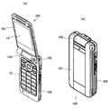
- FIG. 1 is a diagram showing an example of an external structure of a portable electronic device according to an embodiment of the present invention.
- a foldable mobile phone 100 is assumed as the mobile electronic device.
- Mobile phone 100 is also an example of a wireless communication apparatus according to an embodiment of the present invention.
- the mobile phone 100 includes an upper housing 101, a lower housing 102, and a hinge portion 103.
- FIG. 1A is a diagram showing a state (open state) in which the mobile phone 100 is opened
- FIG. 1B is a diagram showing a folded state (closed state) of the mobile phone 100.
- the display unit 14 is disposed on the upper casing 101 on one side that is not exposed to the outside when the cellular phone 100 shown in FIG. 1B is closed.
- the lower housing 102 is provided with an operation unit 12 on one side that is not exposed to the outside when the cellular phone 100 shown in FIG. 1B is closed.
- the hinge portion 103 opens and closes the upper housing 101 and the lower housing 102, and allows the transition between the open state of the mobile phone 100 shown in FIG. 1 (a) and the closed state shown in FIG. 1 (b). It is a hinge mechanism which has.
- the open / closed state of the mobile phone 100 is monitored by the control unit 18 described later, and the control unit 18 can detect the closed state of the mobile phone 100. Specifically, for example, a closed state is detected by the control unit 18 monitoring whether or not a detection switch (not shown) of the lower casing 102 is pushed by a projection (not shown) disposed on the upper casing 101 ( That is, if the detection switch is pressed, it is determined to be in the closed state, otherwise, it is determined to be in the open state).
- the open / close detection is not limited to the switch, and may be various sensors.
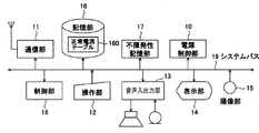
- FIG. 2 is a block diagram showing an internal configuration of the portable electronic device according to the embodiment of the present invention.
- the mobile phone 100 uses the control unit 18 as a control center, and includes a power control unit 10, a communication unit 11, an operation unit 12, a voice input / output unit 13, a display unit 14, an imaging unit 15, a memory.
- Each of the unit 16, the nonvolatile storage unit 17, and the control unit 18 is configured by being commonly connected to a bidirectional system bus 19 including a plurality of lines for address, data, and control.
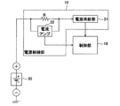
- the power supply control unit 10 includes a power supply unit 31 and a current amplifier 32 as shown in FIG.
- the power supply unit 31 supplies the output current from the battery obtained via the current monitoring resistor (R) connected to the battery 30 to each component block constituting the mobile phone 100.
- the current amplifier 32 connected to both ends of the current monitoring resistor (R) amplifies the voltage drop caused by the current monitoring resistor (R) and supplies the amplified voltage drop to the control unit 18.
- the current amplifier 32 includes a high-magnification voltage amplifier and, for example, an 8-bit AD (Analog to Digital) converter.
- the maximum measurement current is 1 A
- 1A / 12 bits (256) 0.003906A
- Current can be measured with a resolution of. Thereby, it is possible to accurately measure from a low current consumption of several mA as in standby to a large current during wireless transmission and an abnormal current leading to heat generation.
- the communication unit 11 captures a wireless communication system, performs wireless communication with a base station (not shown) connected to the communication network, and transmits and receives various data.
- the various data includes voice data at the time of voice call, mail data at the time of mail transmission / reception, web page data at the time of browsing the web, and the like.
- the operation unit 12 includes keys to which various functions are assigned such as a power key, a call key, a numeric key, a character key, a direction key, a determination key, a call key, and a function key.
- keys to which various functions are assigned such as a power key, a call key, a numeric key, a character key, a direction key, a determination key, a call key, and a function key.
- the audio input / output unit 13 performs input / output processing of an audio signal output from a speaker or an audio signal input from a microphone. That is, the voice input / output unit 13 amplifies the voice input from the microphone, performs analog / digital conversion, further performs signal processing such as encoding, converts it into digital voice data, and outputs it to the control unit 18. .
- the audio input / output unit 13 performs signal processing such as decoding, digital / analog conversion, and amplification on the audio data supplied from the control unit 18, converts the audio data into an analog audio signal, and outputs the analog audio signal to the speaker.
- the display unit 14 is, for example, a liquid crystal display (LCD). And an organic EL display (OLED: Organic Light Emitted Diode), and displays an image corresponding to the video signal supplied from the control unit 18.
- the display unit 14 is a display based on an application program to be executed, for example, a telephone number of a transmission destination at the time of wireless transmission by the communication unit 11, a telephone number of a transmission source at the time of incoming call, contents of received mail or transmitted mail, date, time, The remaining battery level, success / failure of transmission, standby screen, etc. are displayed.
- the imaging unit 15 is a camera configured by a photoelectric conversion element such as a CCD (Charge-Coupled Device) or a CMOS (Complementary Metal-Oxide Semiconductor) image sensor and its control circuit.
- a photoelectric conversion element such as a CCD (Charge-Coupled Device) or a CMOS (Complementary Metal-Oxide Semiconductor) image sensor and its control circuit.
- the storage unit 16 stores various data used for various processes of the mobile phone 100.
- Various setting data and temporary data used in the process of the program are stored.
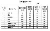
- a current threshold value (normal current table 160) set for each application program and an overcurrent threshold value that is larger than any current threshold value are stored.
- An example of the data structure of the normal current table 160 is shown in FIG.
- the normal current table 160 includes an operation mode A, a current determination value B [mA], a current abnormality determination time E (s), an operation mode register C, and a table No (each entry).
- the non-use determination time D [s] is composed of data items.
- the operation mode A the type of application program (hereinafter simply referred to as an application) (here, as an example, sleep, call application, mail application, WAP (Wireless Application Protocol), DSA (Download Service Application Program), music playback App, 1Seg App).
- a call application is an application that controls communication of the communication unit 11.
- a threshold value (current determination value B [mA]) that is determined to be abnormal is defined for each application type.
- the time which continues exceeding a current determination value for every application is counted, and the current abnormality determination condition is defined as the current abnormality determination time E [s] with respect to the continuous time. Furthermore, a grace period until resetting is set for each application as a non-use determination time D in consideration of user convenience.
- a common current threshold is defined in the table No. 8 for each application.
- the storage unit 16 is configured by, for example, a nonvolatile storage device (nonvolatile semiconductor memory, hard disk device, optical disk device, etc.), a randomly accessible storage device (eg, SRAM, DRAM), or the like.
- a nonvolatile storage device nonvolatile semiconductor memory, hard disk device, optical disk device, etc.
- a randomly accessible storage device eg, SRAM, DRAM
- a register (operation mode register) is allocated to the nonvolatile storage unit 17, and the current value measured by the power supply control unit 10 exceeds the current threshold corresponding to the type of the application program currently being executed. In this case, information indicating the type of the application program is stored. Details will be described later.
- the control unit 18 comprehensively controls the overall operation of the mobile phone 100.
- the control unit 18 performs various processes of the mobile phone 100 (voice calls performed via a circuit switching network, creation and transmission / reception of e-mails, browsing of the Internet Web (World Wide Web) site, etc.).
- the operation of each block described above is controlled so as to be executed in an appropriate procedure according to the operation.
- the control unit 18 includes a computer (microprocessor) that executes processing based on a program (operating system, application program, etc.) stored in the storage unit 16, and performs the above-described processing according to a procedure instructed in this program. Execute.
- instruction codes are sequentially read from programs such as an operating system and application programs stored in the storage unit 16 to execute processing.
- the mobile phone 100 intermittently receives signals from the base station in a standby state for wireless communication.
- the control unit 18 enters a sleep state at a timing when intermittent reception is not performed. And when operation to the operation part 12 is performed or the timing which performs intermittent reception comes, the sleep state of the control part 18 is cancelled
- the control unit 18 monitors the current value measured by the power supply control unit 10 and the type of the application program being executed, and the current threshold value (current determination value) measured by the power supply control unit 10 is currently being executed. It has a function of executing a reset process when the current threshold value corresponding to the type of application program is exceeded or executing a power-off process by the battery 30. Here, the reset process is to forcibly stop the application program.
- the power-off process is to stop all power supply by the battery 30 and turn off the mobile phone 100.
- the control unit 18 stores information indicating the type of the application program in the nonvolatile storage unit 17 has the function of storing.
- control unit 18 has a function of forcibly executing the power-off process regardless of the application program being executed when the current value measured by the power control unit 10 exceeds the excessive current value.
- control unit 18 has a function of executing the power-off process at the timing when the number of times that the excessive current value is exceeded reaches a predetermined number.
- control unit 18 starts measuring time when the current value measured by the power supply control unit 10 exceeds the threshold set for each application program and is lower than the excessive current value.
- Has a function of executing a reset process when it continues for a predetermined time. At this time, the control unit 18 executes the reset process using a different time length for each application program as a predetermined time.
- control unit 18 has a function of monitoring an interrupt and executing a reset process when the interrupt is not used for a predetermined time. Details of each function of the control unit 18 will be described later.
- the control unit 18 uses the current determination value defined in the normal current table 160 stored in the storage unit 16 as the current value measured by the power supply control unit 10.
- System reset reset processing
- the time during which the user is not using the mobile phone 100 is counted.
- Perform a reset As a result, it is possible to avoid the inconvenience of causing a system reset while the user is using the mobile phone 100.
- the non-use determination time can be determined by monitoring the occurrence of interrupt processing by the control unit 18 and counting the time during which no interrupt is detected.
- the non-use determination time D [s] is long so that the reset is not noticed as much as possible.
- the current value may cause heat generation. If the conditions are met regardless of whether the user is using or not using the device, immediate reset processing is performed, and even if multiple system resets are performed, recovery is not possible if the device does not recover from the state where excessive current flows. An abnormality due to destruction or the like is determined and the power is turned off to stop the operation of the mobile phone 100.
- an operation mode register C is assigned to each application, and if an abnormality occurs during execution of a certain application, the register bit assigned to that application (operation mode) is set to “1”, and the detected current value is stored. Keep it.
- the contents of the mode register C and the abnormal current value are stored in the nonvolatile storage unit 17. For this reason, for example, when the abnormal state does not continue due to the removal of the battery 30, etc. (bugs often return to the normal state by removing the battery 30 and restarting it), it was brought in for repair It is possible to confirm under what circumstances an abnormality has occurred in a manufacturer or the like, and the effect of performing quick and accurate analysis can also be obtained.
- the register is taken as an example, other memories may be used as long as they are nonvolatile storage means.
- FIG. 5 is a graph showing the relationship between the current determination value and the current abnormality determination time.
- the control unit 18 is abnormal when a current of 10 [mA] or more flows for 360 [s] or more during sleep. judge.
- the current determination value and time during the call are applied, so that it is not determined to be abnormal under the same conditions as during sleep. That is, with reference to the table No. 2 in the normal current table 160, the control unit 18 determines that an abnormality occurs when a current of 800 [mA] or more flows for 60 [s] or more during a call. Further, when a current exceeding 900 [mA] flows, the control unit 18 determines that there is an immediate abnormality without depending on the application (operation mode) being executed.
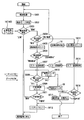
- FIG. 6 is a flowchart showing a detailed operation of the portable electronic device according to the embodiment of the present invention.
- a solid arrow indicates a sequence flow
- a dotted arrow indicates data read / write (R / W).
- the control unit 18 monitors the current flowing through the current monitoring resistor R based on the current measured by the power supply control unit 10 (step S601: current monitoring). For example, in the case of intermittent reception of CDMA (Code Division Multiple Access), the monitoring timing is performed every 5.12 s.
- the control unit 18 determines the type of the application currently being executed (step S602: operation mode determination). Then, the monitored current value is compared with the current determination value B [mA] of the operation mode of the corresponding application defined in the normal current table 160 stored in the storage unit 16 (step S603: current abnormality determination).
- step S604 dangerous current
- step S605 abnormal time count
- step S606 the control unit 18 performs the abnormal time determination (step S606), and the current abnormal count value may continue longer than the operation abnormal determination time E defined in the normal current table 160 stored in the storage unit 16. If this is the case (step S606 “time elapsed”), it is determined that the operation is abnormal, and an error recording process is performed (step S607).
- the error recording process is a process of setting the operation mode register defined in the normal current table 160 corresponding to the operation mode in which an error has occurred to “1” and storing the current value.
- the operation mode register and the current value are allocated to the nonvolatile storage unit 17 and set in a predetermined error storage area.
- step S612 system reset
- non-use time The time when the user is not using the mobile phone (non-use time) is measured by the control unit 18 monitoring interrupts (step S608: interrupt determination) and counting the time when interrupts do not occur continuously. (Step S609: Non-use time count).
- Step S609 Non-use time count.
- the value of the unused counter (counter assigned on the program) is returned to “0”, and the time when there is no interrupt is counted again (step S610: unused counter reset).
- control unit 18 determines that the mobile phone is not used with reference to the above-described non-use counter (step S611). In this non-use determination, if the non-use counter value exceeds the non-use determination time D defined in the normal current table 160, the control unit 18 performs system reset processing (step S612), and monitors the current in step S601. Return to processing. As described above, the nonuse determination time D [s] can be set for each operation mode. Further, the unused time count (step S609) and the unused time determination (step S611) are performed at the same timing as the current monitoring described above.
- step S604 when it is determined that the current is an excessive current (step S604 “excessive current”), the control unit 18 adds the number of times determined to be an excessive current (overcurrent count value) (step S613: excessive current count). The number of times is stored in a predetermined area of the storage unit 16. At this time, the control unit 18 further performs error recording processing (step S614).
- the error recording process here is a process of setting the operation mode register defined in the normal current table 160 corresponding to the operation mode in which an error has occurred to “1” and storing the excessive current value.
- the operation mode register and the current value are allocated to the nonvolatile storage unit 17 and set in a predetermined error storage area.
- control unit 18 refers to the excessive current count value (S616: supply stop determination), and if the number of times determined to be an excessive current exceeds a predetermined number (xx times) (step S616 "xx times or more"). It is determined that recovery by system reset is impossible (current increase due to device destruction, etc.). Then, the number of times determined to be an excessive current is reset, and power supply is stopped to prevent a state such as heat generation (power-off process) (step S617). Then, the operation of the mobile phone 100 ends.
- S616 supply stop determination
- step S616 “less than xx times”
- step S612 system reset processing is performed regardless of whether the user is using or not.
- the number of times determined to be an excessive current is not reset.
- the predetermined number of times (xx times) for determining that recovery by system reset is impossible may be one time or a plurality of times.
- the control unit 18 automatically returns to normal when the abnormality is determined. It can be made. As a result, the normal state can be restored without requiring a highly resistive operation by the user such as pressing the reset button.
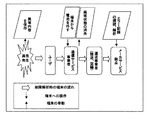
- FIG. 7 shows the flow of the portable electronic device at the time of failure analysis, the operation to the portable electronic device, and the behavior of the portable electronic device.
- the portable electronic device since the state at the time of occurrence of an abnormality is recorded, the cost and time for maintenance, cause analysis, and repair can be reduced. It can also be used to detect soft bugs that require enormous amounts of time when developing new models.
- the cellular phone 100 is illustrated as the portable electronic device according to the above-described embodiment of the present invention, but a portable electronic device driven by a power source, for example, a PDA (Personal Digital Assistants), an electronic notebook, and a game machine is also used.
- a portable electronic device driven by a power source for example, a PDA (Personal Digital Assistants), an electronic notebook, and a game machine is also used.
- all the functions of the control unit 18 shown in FIG. 3 may be realized by software, or at least a part thereof may be realized by hardware.
- the current value measured by the power supply control unit 10 and the type of the application program being executed are monitored, and the current value measured by the power supply control unit 10 corresponds to the type of the application program currently being executed.
- Data processing in the control unit 18 that executes reset processing when the threshold value is exceeded or executes power-off processing by the battery 30 may be realized on a computer by one or a plurality of programs, and at least one of them is performed.
- the unit may be
Landscapes
- Engineering & Computer Science (AREA)
- Computer Networks & Wireless Communication (AREA)
- Signal Processing (AREA)
- Telephone Function (AREA)
- Power Sources (AREA)
Abstract
Description
なお、通常の待受け状態の消費電流は3mA程度である。
カメラモードになると、CPU82はカメラデバイス83の電源をONする処理を実行する(ステップS803)。
このとき、消費電流は、状態Bで示す200mAになる。カメラモードを終了する場合(ステップS804)、CPU200は、カメラデバイス300の電源OFF処理を実行する。しかし、何らかのバグで電源OFFを指示する情報がカメラデバイス283に到達せずカメラオフ処理が実行できなかった場合、携帯電話は待受け状態にあるため(ステップS805)、本来なら消費電流は状態Aの3mA程度になるが、バグによってカメラデバイス83がONになったままであるため、200mAの余計な電流を消費してしまう。
図1に示されるように、携帯電話100は、上部筐体101と、下部筐体102と、ヒンジ部103とを有する。
図1(a)に示されるように、上部筐体101には、図1(b)に示す携帯電話100の閉状態においては外部には露出しない一面に表示部14が配置されている。
また、図1(a)に示されるように、下部筐体102には、図1(b)に示す携帯電話100の閉状態において外部には露出しない一面に操作部12が配置されている。
具体的には、例えば上部筐体101に配置した図示しない突起部により、下部筐体102の図示しない検出スイッチが押しているか否かを制御部18が監視することにより閉状態を検出している(すなわち検出スイッチが押下されていれば閉状態、そうでなければ開状態と判定)。なお、開閉検出は、スイッチに限らず、各種センサであってもよい。
電源供給部31は、電池30に接続された電流監視抵抗(R)を介して得られる電池からの出力電流を、携帯電話100を構成する各構成ブロックに供給する。また、電流監視抵抗(R)の両端に接続された電流アンプ32は、電流監視抵抗(R)による電圧降下を増幅して制御部18に供給する。
これにより、待受け時のような数mAの低消費電流から無線送信時の大電流、また発熱に至る異常電流までの正確な測定を可能とする。
すなわち、音声入出力部13は、マイクロフォンから入力された音声を増幅し、アナログ/デジタル変換を行い、更に符号化等の信号処理を施し、デジタルの音声データに変換して制御部18に出力する。 また、音声入出力部13は、制御部18から供給される音声データに復号化、デジタル/アナログ変換、増幅等の信号処理を施し、アナログの音声信号に変換してスピーカに出力する。
や有機ELディスプレイ(OLED:Organic Light Emitted Diode)を用いて構成され
ており、制御部18から供給される映像信号に応じた画像を表示する。
表示部14は、実行するアプリケーションプログラムに基づく表示、例えば、通信部11による無線発信時における発信先の電話番号、着信時における発信元の電話番号、受信メールや送信メールの内容、日付、時刻、電池残量、発信成否、待ち受け画面等を表示する。
ここでは、特に、アプリケーションプログラム毎に設定される電流閾値(正常電流テーブル160)、ならびに、いずれの電流閾値よりも大きな値である過大電流閾値が記憶されている。正常電流テーブル160のデータ構造の一例が図4に示されている。
ここでは、動作モードAとして、アプリケーションプログラム(以下、単にアプリという)の種別(ここでは、一例としてスリープ、通話アプリ、メールアプリ、WAP(Wireless Application Protocol)、DSA(Download Service Application Program)、音楽再生アプリ、ワンセグアプリ)が示される。この中で、例えば通話アプリは通信部11の通信を制御するアプリである。そして、これらアプリ種別毎に、異常と判定される閾値(電流判定値B[mA])が定義されている。また、アプリ毎に電流判定値を超えて継続する時間をカウントし、その継続時間に関して、電流異常判定時間E[s]として電流異常の判定条件を定義している。更に、ユーザの使い勝手を考慮して不使用判定時間Dとしてアプリ毎にリセットを行うまでの猶予時間を設定している。なお、各アプリ共通に、テーブルNo8に危険電流閾値が定義されている。
すなわち、制御部18は、携帯電話100の各種処理(回線交換網を介して行われる音声通話、電子メールの作成と送受信、インターネットのWeb(World Wide Web)サイトの閲覧など)が操作部12の操作に応じて適切な手順で実行されるように、上述した各ブロックの動作(通信部11における信号の送受信、表示部14における画像の表示、撮像部15における撮像処理等)を制御する。
制御部18は、記憶部16に格納されるプログラム(オペレーティングシステム、アプリケーションプログラム等)に基づいて処理を実行するコンピュータ(マイクロプロセッサ)を備えており、このプログラムにおいて指示された手順に従って上述した処理を実行する。すなわち、記憶部16に格納されるオペレーティングシステムやアプリケーションプログラム等のプログラムから命令コードを順次読み込んで処理を実行する。
なお、携帯電話100は無線通信のために、待ち受け状態では基地局からの信号を間欠受信している。 操作部12への操作が所定時間行われなかった場合、間欠受信を行わないタイミングには、制御部18はスリープ状態となる。そして、操作部12への操作が行われるまたは、間欠受信を行うタイミングが到来した場合に制御部18のスリープ状態が解除される。
また、制御部18は、電源制御部10により計測される電流値が、現在実行中のアプリケーションプログラムの種別に対応する電流閾値を超えた場合に、アプリケーションプログラムの種別を示す情報を不揮発性記憶部17に記憶する機能を有する。
また、制御部18は、電源制御部10により計測される電流値が、アプリケーションプログラム毎に設定される閾値を超え、かつ、過大電流値より低い状態を検出した場合に計時を開始し、当該状態が所定時間継続した場合にリセット処理を実行する機能を有する。このとき、制御部18は、アプリケーションプログラム毎に異なる時間長を所定時間としてリセット処理を実行する。
上記した制御部18が有する各機能の詳細はいずれも後述する。
すなわち、制御部18は、あるアプリ実行中に電流監視を行った結果、電源制御部10で計測された電流値が、記憶部16に記憶された正常電流テーブル160に定義された電流判定値を越えた場合にシステムリセット(リセット処理)を行うが、異常発熱に至るような過大電流値でない場合は、携帯電話100をユーザが使用していない時間(不使用判定時間D)をカウントしてシステムリセットを行う。
このことにより、ユーザが携帯電話100使用中にシステムリセットを発生させるという不便さを回避することができる。なお、不使用判定時間は、制御部18が割り込み処理の発生を監視し、割り込みが検出されない時間をカウントすることにより判定が可能である。
このことにより、例えば、電池30が外される等により異常な状態が継続しない場合(バグは電池30をはずして再起動させることにより正常状態に戻ることが多い)、修理のために持ち込まれたメーカ等において異常がどのような状況で発生していたのか確認できるようなり、迅速、かつ正確な解析を行う効果も得られる。レジスタを例としたが、不揮発の記憶手段ならば他のメモリでもよい。
すなわち、正常電流テーブル160のテーブルNo2を参照して、制御部18は、通話時に800[mA]以上の電流が60[s]以上流れた場合に異常であると判定する。さらに、900[mA]を超える電流が流れた場合、制御部18は、実行中のアプリ(動作モード)に依存することなく即時異常と判定する。
以下、図6のフローチャートを参照しながら、図1~図5に示す本発明の実施の形態に係る携帯電子機器の動作について説明する。
次に、制御部18は、現在実行中のアプリの種別を判定する(ステップS602:動作モード判定)。そして、監視電流値と、記憶部16に記憶されている正常電流テーブル160に定義された該当するアプリの動作モードの電流判定値B[mA]と比較する(ステップS603:電流異常判定)。ここで、監視電流値が電流判定値Bを超えていた場合(S603“異常”)、更に、監視電流値が例えば900[mA]の危険電流を超えていないか判定する(ステップS604:危険電流判定)。監視電流値が危険電流値を越えていない場合は(ステップS604“安全”)、電流判定値を超えている異常時間をカウントする(ステップS605:異常時間カウント)。
なお、不使用判定時間D[s]は動作モード毎に設定できるようにしておくことは上記したとおりである。また、この不使用時間のカウント(ステップS609)、および不使用判定(ステップS611)は上記した電流監視と同じタイミングで行う。
すなわち、従来は、異常動作時にユーザがリセット操作を行う必要があったが、本発明の実施の形態に係る携帯電子機器によれば、制御部18が異常を判定することで自動的に正常復帰させることが出来る。このことにより、リセットボタンを押すといったユーザに抵抗の強い操作を必要とせずに正常な状態を復元できる。
但し発熱に至るような過大な電流に対しては、過大電流の回数をカウントし、複数回のシステムリセットを行っても正常復帰しない場合に復帰不可能と判定して電源供給を停止する制御を行う。このことにより、携帯電子機器の故障、破壊を未然に防ぐことができる。
これに対し、本発明の実施の形態に係る携帯電子機器によれば、異常発生時の状態を記録するため、保守、原因解析、修理にかかる費用や時間を削減できる。さらに次の新機種開発時に膨大な時間が必要であるソフトバグの検出としても利用が可能である。
また、図3に示す制御部18が有する機能は、全てをソフトウェアによって実現しても、あるいはその少なくとも一部をハードウェアで実現してもよい。
例えば、電源制御部10により計測される電流値と、実行中のアプリケーションプログラムの種別とを監視し、電源制御部10により計測された電流値が、現在実行中のアプリケーションプログラムの種別に対応する電流閾値を超えた場合にリセット処理を実行し、もしくは電池30による電源遮断処理を実行する制御部18におけるデータ処理は、1または複数のプログラムによりコンピュータ上で実現してもよく、また、その少なくとも一部をハードウェアで実現してもよい。
本出願は、2008年1月30日出願の日本特許出願・出願番号2008-019978に基づくものであり、その内容はここに参照として取り込まれる。
Claims (11)
- 電池と、
前記電池に接続されて、当該電池から出力される出力電流監視抵抗に流れる電流を計測する電流計測部と、
各種アプリケーションプログラムを実行する制御部と、
前記制御部にて実行可能な複数のアプリケーションプログラム毎に設定される電流閾値を記憶する記憶部と、を備え、
前記制御部は、
前記電流計測部により計測される電流値と、実行中のアプリケーションプログラムの種別とを監視し、前記電流計測部により計測された電流値が、現在実行中のアプリケーションプログラムの種別に対応する電流閾値を超えた場合にリセット処理または電源オフ処理を実行する
携帯電子機器。 - 不揮発性記憶部を更に備え、
前記制御部は、
前記電流計測部により計測される電流値が、現在実行中のアプリケーションプログラムの種別に対応する電流閾値を超えた場合に、前記実行中のアプリケーションプログラムの種別を示す情報を前記不揮発性記憶部に記憶する
請求項1に記載の携帯電子機器。 - 前記記憶部には、前記アプリケーションプログラム毎に設定される電流閾値の他に、いずれの電流閾値よりも大きな値である過大電流閾値を記憶しており、
前記制御部は、
前記電流計測部により計測される電流値が前記過大電流値を超えた回数が所定回数に達したことを契機として、実行中のアプリケーションプログラムに係らず強制的に電源オフ処理を実行する
請求項1または2に記載の携帯電子機器。 - 前記所定の回数は複数回である
請求項3に記載の携帯電子機器。 - 前記記憶部には、前記アプリケーションプログラム毎に設定される電流閾値の他に、いずれの電流閾値よりも大きな値である過大電流閾値を記憶しており、
前記制御部は、
前記電流計測部により計測される電流値が前記過大電流値を超えたことを契機として、リセット処理を実行する
請求項1または2に記載の携帯電子機器。 - 前記制御部は、
前記電流計測部により計測される電流値が前記過大電流値を超えた回数が所定回数に達するまで、前記電流値が前記過大電流値を超えたことを契機としてリセット処理を実行し、
前記電流計測部により計測される電流値が前記過大電流値を超えた回数が所定回数に達した場合には、実行中のアプリケーションプログラムに係らず強制的に電源オフ処理を実行する
請求項5に記載の携帯電子機器。 - 前記制御部は、
前記電流計測部により計測される電流値が、前記複数のアプリケーションプログラム毎に設定される電流閾値を超える状態を検出した場合に計時を開始し、当該状態が第1所定時間継続した場合に前記リセット処理を実行する
請求項1から6のいずれかに記載の携帯電子機器。 - 前記制御部は、
前記複数のアプリケーションプログラム毎に異なる時間長を前記第1所定時間として前記リセット処理を実行する
請求項7に記載の携帯電子機器。 - 前記制御部は、
割り込み処理の発生を監視し、前記リセット処理を実行する際には、前記割り込み処理の発生が第2所定時間内不使用状態になった時点で当該リセット処理を実行する
請求項1から8のいずれかに記載の携帯電子機器。 - 前記制御部は、
前記複数のアプリケーションプログラム毎に異なる時間長を前記第2所定時間として前記リセット処理を実行する
請求項9に記載の携帯電子機器。 - 電池と、
前記電池に接続されて、当該電池から出力される出力電流監視抵抗に流れる電流を計測する電流計測部と、
無線通信を行う通信部と、
通信部の通信を制御するアプリケーションプログラムおよび各種アプリケーションプログラムを実行する制御部と、
前記制御部にて実行可能な複数のアプリケーションプログラム毎に設定される電流閾値を記憶する記憶部と、を備え、
前記制御部は、
前記電流計測部により計測される電流値と、実行中のアプリケーションプログラムの種別とを監視し、前記電流計測部により計測された電流値が、現在実行中のアプリケーションプログラムの種別に対応する電流閾値を超えた場合にリセット処理、または電源オフ処理を実行する
無線通信装置。
Priority Applications (2)
| Application Number | Priority Date | Filing Date | Title |
|---|---|---|---|
| US12/865,209 US8543173B2 (en) | 2008-01-30 | 2009-01-30 | Portable electronic device and wireless communication device |
| KR1020107016983A KR101164559B1 (ko) | 2008-01-30 | 2009-01-30 | 휴대전자기기 및 무선통신장치 |
Applications Claiming Priority (2)
| Application Number | Priority Date | Filing Date | Title |
|---|---|---|---|
| JP2008-019978 | 2008-01-30 | ||
| JP2008019978A JP5259205B2 (ja) | 2008-01-30 | 2008-01-30 | 携帯電子機器 |
Publications (1)
| Publication Number | Publication Date |
|---|---|
| WO2009096567A1 true WO2009096567A1 (ja) | 2009-08-06 |
Family
ID=40912910
Family Applications (1)
| Application Number | Title | Priority Date | Filing Date |
|---|---|---|---|
| PCT/JP2009/051663 Ceased WO2009096567A1 (ja) | 2008-01-30 | 2009-01-30 | 携帯電子機器および無線通信装置 |
Country Status (4)
| Country | Link |
|---|---|
| US (1) | US8543173B2 (ja) |
| JP (1) | JP5259205B2 (ja) |
| KR (1) | KR101164559B1 (ja) |
| WO (1) | WO2009096567A1 (ja) |
Cited By (1)
| Publication number | Priority date | Publication date | Assignee | Title |
|---|---|---|---|---|
| JP2011095927A (ja) * | 2009-10-28 | 2011-05-12 | Fujitsu Ltd | 情報生成装置、情報生成方法及び情報生成プログラム |
Families Citing this family (18)
| Publication number | Priority date | Publication date | Assignee | Title |
|---|---|---|---|---|
| US20120167218A1 (en) * | 2010-12-23 | 2012-06-28 | Rajesh Poornachandran | Signature-independent, system behavior-based malware detection |
| EP2493161A1 (en) * | 2011-02-25 | 2012-08-29 | Research In Motion Limited | Method and apparatus for managing power levels in a handheld mobile communication device |
| JP2012208739A (ja) * | 2011-03-30 | 2012-10-25 | Nec Saitama Ltd | 端末装置並びにフリーズ検出方法及び端末装置の制御方法 |
| EP2575399A1 (en) * | 2011-09-30 | 2013-04-03 | Hitachi, Ltd. | System configured to be communicably connected to network nodes of a communication network |
| CN103198256B (zh) * | 2012-01-10 | 2016-05-25 | 凹凸电子(武汉)有限公司 | 用于检测应用程序状态的检测系统及方法 |
| JP2014120806A (ja) * | 2012-12-13 | 2014-06-30 | Toshiba Corp | 情報処理装置、制御方法及び制御プログラム |
| CA2849383C (en) * | 2013-08-20 | 2016-06-07 | Yasunori Kimura | Construction machine controller |
| CN103544088A (zh) * | 2013-09-30 | 2014-01-29 | 东莞宇龙通信科技有限公司 | 一种检测终端功耗异常的方法及装置 |
| JP6303486B2 (ja) * | 2013-12-24 | 2018-04-04 | 日本電気株式会社 | 情報処理システム、監視方法、及び、プログラム |
| TWI526815B (zh) * | 2014-09-10 | 2016-03-21 | 秦祖敬 | 智慧電源監控系統及其實施方法 |
| JP5896066B2 (ja) * | 2015-04-02 | 2016-03-30 | 富士通株式会社 | プロセッサシステム、および制御プログラム |
| US9837020B2 (en) * | 2015-05-28 | 2017-12-05 | Dell Products L.P. | Power control in an organic light emitting diode (OLED) display device |
| KR102465543B1 (ko) * | 2016-02-19 | 2022-11-10 | 삼성전자 주식회사 | 어플리케이션 및 컴포넌트를 제어하는 방법 및 전자장치 |
| WO2017156676A1 (zh) * | 2016-03-14 | 2017-09-21 | 华为技术有限公司 | 一种针对应用的处理方法、装置及智能终端 |
| JP6955092B2 (ja) * | 2017-10-13 | 2021-10-27 | ホアウェイ・テクノロジーズ・カンパニー・リミテッド | 端末の電力消費を低減するための方法、および端末 |
| JP7272694B2 (ja) * | 2017-10-13 | 2023-05-12 | ホアウェイ・テクノロジーズ・カンパニー・リミテッド | 端末の電力消費を低減するための方法、および端末 |
| KR20210063786A (ko) | 2019-11-25 | 2021-06-02 | 삼성전자주식회사 | 하드웨어 리셋 제어 방법 및 전자 장치 |
| JP7568401B2 (ja) * | 2020-01-08 | 2024-10-16 | 古野電気株式会社 | 増幅装置、レーダ装置、および、増幅方法 |
Citations (5)
| Publication number | Priority date | Publication date | Assignee | Title |
|---|---|---|---|---|
| JPH0522834A (ja) * | 1991-07-05 | 1993-01-29 | Hitachi Ltd | 情報処理装置 |
| JPH0837720A (ja) * | 1994-07-26 | 1996-02-06 | Giden Kogyo:Kk | 自動安全ブレーカー |
| JPH09319941A (ja) * | 1996-05-27 | 1997-12-12 | Sanyo Electric Co Ltd | 自動販売機の異常検知装置 |
| JPH10322878A (ja) * | 1997-05-14 | 1998-12-04 | Tokyo Densetsu Service Kk | 過電流保護用開閉装置 |
| JP2006271077A (ja) * | 2005-03-23 | 2006-10-05 | Nec Corp | 携帯型電子機器 |
Family Cites Families (6)
| Publication number | Priority date | Publication date | Assignee | Title |
|---|---|---|---|---|
| JP2001197197A (ja) * | 2000-01-17 | 2001-07-19 | Funai Electric Co Ltd | 携帯型電話機、及び、記憶媒体 |
| JP2004064291A (ja) | 2002-07-26 | 2004-02-26 | Matsushita Electric Ind Co Ltd | 携帯電話端末 |
| DE102004056436B4 (de) * | 2004-11-19 | 2019-04-04 | Jenoptik Advanced Systems Gmbh | Verfahren und Vorrichtung zur Erkennung von Fehlerstrom-Lichtbögen in elektrischen Stromkreisen |
| JP5092218B2 (ja) * | 2005-09-06 | 2012-12-05 | 富士通株式会社 | 電池パックの異常検出方法、電池パック及び電子機器 |
| US20080200220A1 (en) * | 2007-02-16 | 2008-08-21 | Jackson Bruce K | Methods and devices for limiting battery power consumption in a wireless communication device |
| US20090098914A1 (en) * | 2007-10-15 | 2009-04-16 | Research In Motion Limited | Method and system for enabling or disabling features based on a battery level threshold |
-
2008
- 2008-01-30 JP JP2008019978A patent/JP5259205B2/ja not_active Expired - Fee Related
-
2009
- 2009-01-30 US US12/865,209 patent/US8543173B2/en not_active Expired - Fee Related
- 2009-01-30 KR KR1020107016983A patent/KR101164559B1/ko not_active Expired - Fee Related
- 2009-01-30 WO PCT/JP2009/051663 patent/WO2009096567A1/ja not_active Ceased
Patent Citations (5)
| Publication number | Priority date | Publication date | Assignee | Title |
|---|---|---|---|---|
| JPH0522834A (ja) * | 1991-07-05 | 1993-01-29 | Hitachi Ltd | 情報処理装置 |
| JPH0837720A (ja) * | 1994-07-26 | 1996-02-06 | Giden Kogyo:Kk | 自動安全ブレーカー |
| JPH09319941A (ja) * | 1996-05-27 | 1997-12-12 | Sanyo Electric Co Ltd | 自動販売機の異常検知装置 |
| JPH10322878A (ja) * | 1997-05-14 | 1998-12-04 | Tokyo Densetsu Service Kk | 過電流保護用開閉装置 |
| JP2006271077A (ja) * | 2005-03-23 | 2006-10-05 | Nec Corp | 携帯型電子機器 |
Cited By (1)
| Publication number | Priority date | Publication date | Assignee | Title |
|---|---|---|---|---|
| JP2011095927A (ja) * | 2009-10-28 | 2011-05-12 | Fujitsu Ltd | 情報生成装置、情報生成方法及び情報生成プログラム |
Also Published As
| Publication number | Publication date |
|---|---|
| US8543173B2 (en) | 2013-09-24 |
| JP5259205B2 (ja) | 2013-08-07 |
| KR20100098456A (ko) | 2010-09-06 |
| JP2009181366A (ja) | 2009-08-13 |
| US20100331057A1 (en) | 2010-12-30 |
| KR101164559B1 (ko) | 2012-07-10 |
Similar Documents
| Publication | Publication Date | Title |
|---|---|---|
| JP5259205B2 (ja) | 携帯電子機器 | |
| KR101941510B1 (ko) | 전력 소모를 줄이기 위한 방법 및 그 전자 장치 | |
| JP5079533B2 (ja) | 携帯電子機器 | |
| JP5439715B2 (ja) | 携帯端末、制御方法、プログラム、及び記録媒体 | |
| CN103365389B (zh) | 功耗控制方法及其装置 | |
| US20090309745A1 (en) | System and method for accessing diagnostic information | |
| CN101960461A (zh) | 消费者不恰当使用检测系统和方法 | |
| US20070135105A1 (en) | Mobile information terminal executing application program | |
| US8850264B2 (en) | Information terminal and information processing method | |
| CN106451670B (zh) | 一种充电控制方法、装置及终端设备 | |
| TW201308830A (zh) | 手持式電子裝置的備用電力系統及備用電力供應方法 | |
| CN103683340A (zh) | 使用电池作为电源的装置的电源管理设备及方法 | |
| JP2007166774A (ja) | 携帯型電子機器及びその内蔵電池の充電方法 | |
| JP2009206839A (ja) | 電子機器および電子機器における消費電流測定方法 | |
| JP2004341755A (ja) | 情報処理装置 | |
| TW201430543A (zh) | 保護裝置及其保護方法與電子系統 | |
| CN106598195A (zh) | 功耗控制方法及其装置 | |
| JP5478052B2 (ja) | 電子機器 | |
| JP5433205B2 (ja) | 電子機器 | |
| KR100455766B1 (ko) | 이동통신 단말기에서 발생된 단말기 결함정보 통보방법 | |
| KR200392481Y1 (ko) | 아이알디에이 모듈을 구비하는 충전기 | |
| CN111987764B (zh) | 放电控制方法、装置、存储介质及移动终端 | |
| JP2011114934A (ja) | 保護回路 | |
| JP3861616B2 (ja) | 携帯端末の電源管理装置 | |
| JP2009506430A5 (ja) |
Legal Events
| Date | Code | Title | Description |
|---|---|---|---|
| 121 | Ep: the epo has been informed by wipo that ep was designated in this application |
Ref document number: 09706102 Country of ref document: EP Kind code of ref document: A1 |
|
| ENP | Entry into the national phase |
Ref document number: 20107016983 Country of ref document: KR Kind code of ref document: A |
|
| WWE | Wipo information: entry into national phase |
Ref document number: 12865209 Country of ref document: US |
|
| NENP | Non-entry into the national phase |
Ref country code: DE |
|
| 122 | Ep: pct application non-entry in european phase |
Ref document number: 09706102 Country of ref document: EP Kind code of ref document: A1 |